
SubMix - Professional audio equipment Radial Engineering - Free user manual and instructions
Find the device manual for free SubMix Radial Engineering in PDF.


| Product Type | Subwoofer Mixer / Processor |
| Brand | Radial Engineering |
| Model | SubMix |
| Rack Size | 1U (19-inch rack-mountable) |
| Dimensions | 483 mm x 44 mm x 152 mm (19" x 1.75" x 6") |
| Weight | 2.3 kg (5 lbs) |
| Power Supply | 9V DC, 500 mA (includes external power adapter) |
| Input Connectors | 2x XLR female, balanced |
| Output Connectors | 2x XLR male, balanced (Main and Sub outputs) |
| Frequency Response | 20 Hz - 20 kHz (-0.5 dB) |
| Crossover Frequency | Variable, 50 Hz to 200 Hz |
| Phase Switch | 0° / 180° polarity reversal |
| Subwoofer Level Control | Rotary knob, -∞ to +10 dB |
| Output Level | +4 dBu nominal, maximum +24 dBu |
| Ground Lift | Switchable to eliminate hum |
| Construction | Steel chassis with baked enamel finish |
| Cooling | Passive, no fan |
| Operating Temperature | 0°C to 40°C |
| Warranty | Radial 3-year transferable warranty |
Frequently Asked Questions - SubMix Radial Engineering
User questions about SubMix Radial Engineering
0 question about this device. Answer the ones you know or ask your own.
Ask a new question about this device
Download the instructions for your Professional audio equipment in PDF format for free! Find your manual SubMix - Radial Engineering and take your electronic device back in hand. On this page are published all the documents necessary for the use of your device. SubMix by Radial Engineering.
USER MANUAL SubMix Radial Engineering
natural_image
Five black star and star symbols arranged horizontally, no text or labels presentX ◇ *□ ▲ √ ☆ ■ ☆ ▲

*▲□ ◆✿✿
Radial® engineering
*□◆※▼□▼**☆◆▲**
[Non-Text]
Table of Contents Page
Overview....1
Features 2
Making Connections....3
Ominiport....3
Using the Submix in mono....4
Combining Submix modules for more channels 5
Using the Submix modules in stereo 6
Specifications 7
Block diagram....7
Radial limited warranty ......Back Cover
Congratulations on your purchase of the Radial Submix, an innovative 500 series module that lets you mix 4 line level sources such as keyboards, drum machines, effects returns, computers and just about any other audio source together inside any 500 series rack.
Should you find yourself asking a question that is not addressed, we invite you to view the Submix FAQ page on our web site. This is where we post the latest hints and of course questions from users. If you still do not find what you are looking for, feel free to send an email to info@radialeng.com and we will do our very best to respond to you in short order.
Now get ready to start connecting more cables and wires... cause this is what audio engineers love to do most!

WARNING NOTICE TO USER!
Although preventative safety measures have been designed into Radial 500 series products we strictly advise against hot swapping modules or plugging and unplugging them when the Workhorse or other 500 series rack is powered on. Hot swapping can cause connection sparks at the card-edge connector that could send damaging transients to other equipment. This also greatly reduces the life span of the contacts. Damage due to hot swapping is not covered under warranty. There are no user serviceable parts inside.
OVERVIEW
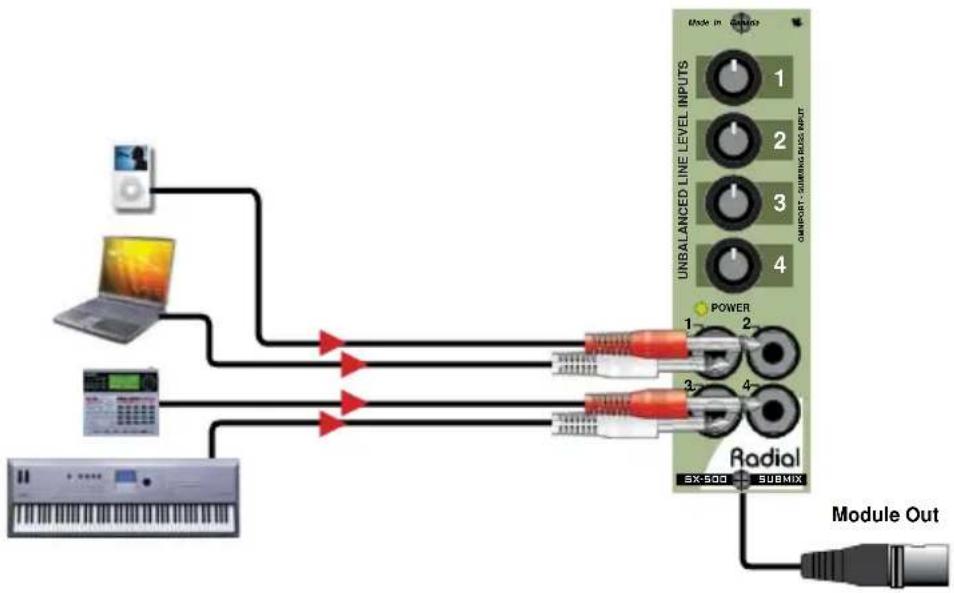
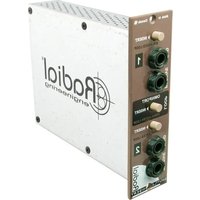
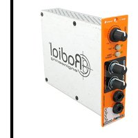
The Submix is a four input, one output mixer (4x1) in a single card slot module designed to fit the 500 series format. It follows convention with the 15-pin edge connector so that it works in all 500 series power racks. Each of the front panel 14 inputs are designed to accommodate all types of unbalanced line level signals. Examples include instruments such as keyboards, samplers and electronic drums, plus line-level sources such as tape machines, effects returns, CD players, iPods, and computer audio outputs. These are then quickly mixed using the four front panel control knobs.
flowchart
graph TD
    A["Audio Input"] --> B["Computer"]
    B --> C["Radio Module Out"]
    D["Laptop"] --> E["UNBALANCED LINE LEVEL INPUTS"]
    E --> F["Radial Module Out"]
    G["Radio Module"] --> H["Power"]
    H --> I["1"]
    H --> J["2"]
    H --> K["3"]
    H --> L["4"]
    M["Radio Module"] --> N["5X-500 SUBMIX"]
    O["Radio Module"] --> P["5X-500 SUBMIX"]
Typical 4x1 line mixer setup.
For those equipped with a Radial Workhorse 500 series power rack, the Omniport functions as an expansion buss to enable two or more Submix modules to be combined creating a larger mixer.

flowchart
graph TD
    subgraph LeftPanel
        A["User Interface"] --> B["Analog Encoder"]
        B --> C["Radiokey"]
        C --> D["UNBALANCED LINE LEVEL INPUTS"]
        D --> E["1"]
        D --> F["2"]
        D --> G["3"]
        D --> H["4"]
        D --> I["Power 1"]
        D --> J["Power 2"]
        D --> K["Power 3"]
        D --> L["Power 4"]
        D --> M["Power 1"]
        D --> N["Power 2"]
        D --> O["Power 3"]
        D --> P["Power 4"]
        D --> Q["Power 1"]
        D --> R["Power 2"]
        D --> S["Power 3"]
        D --> T["Power 4"]
        D --> U["Power 1"]
        D --> V["Power 2"]
        D --> W["Power 3"]
        D --> X["Power 4"]
        D --> Y["Power 1"]
        D --> Z["Power 2"]
        D --> AA["Power 3"]
        D --> AB["Power 4"]
        D --> AC["Power 1"]
        D --> AD["Power 2"]
        D --> AE["Power 3"]
        D --> AF["Power 4"]
        D --> AG["Power 1"]
        D --> AH["Power 2"]
        D --> AI["Power 3"]
        D --> AJ["Power 4"]
        D --> AK["Power 1"]
        D --> AL["Power 2"]
        D --> AM["Power 3"]
        D --> AN["Power 4"]
        D --> AO["Power 1"]
        D --> AP["Power 2"]
        D --> AQ["Power 3"]
        D --> AR["Power 4"]
        D --> AS["Power 1"]
        D --> AT["Power 2"]
        D --> AU["Power 3"]
        D --> AV["Power 4"]
        D --> AW["Power 1"]
        D --> AX["Power 2"]
        D --> AY["Power 3"]
        D --> AZ["Power 4"]
        D --> BA["Power 1"]
        D --> BB["Power 2"]
        D --> BC["Power 3"]
        D --> BD["Power 4"]
        D --> BE["Power 1"]
        D --> BF["Power 2"]
        D --> BG["Power 3"]
        D --> BH["Power 4"]
        D --> BI["Power 1"]
        D --> BJ["Power 2"]
        D --> BK["Power 3"]
        D --> BL["Power 4"]
        D --> BM["Power 1"]
        D --> BN["Power 2"]
        D --> BO["Power 3"]
        D --> BP["Power 4"]
        D --> BQ["Power 1"]
        D --> BR["Power 2"]
        D --> BS["Power 3"]
        D --> BT["Power 4"]
        D --> BU["Power 1"]
        D --> BV["Power 2"]
        D --> BW["Power 3"]
        D --> BX["Power 4"]
        D --> BY["Power 1"]
        D --> BZ["Power 2"]
        D --> CA["Power 3"]
        D --> CB["Power 4"]
        D --> CC["Power 1"]
        D --> CD["Power 2"]
        D --> CE["Power 3"]
        D --> CF["Power 4"]
        D --> CG["Power 1"]
        D --> CH["Power 2"]
        D --> CI["Power 3"]
        D --> CJ["Power 4"]
        D --> CK["Power 1"]
Using the Omniport buss input to create an 8x1 line mixer (Radial Workhorse power rack only).
FEATURE SET
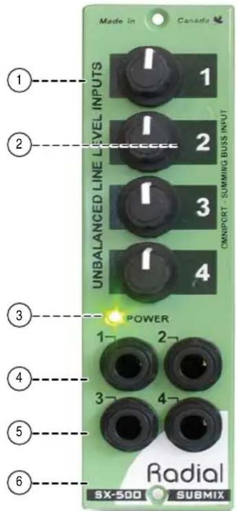
- LEVEL 1 thru 4: Accustate input control, simultaneously adjusts the sensitivity and gain for maximum signal to noise. Use to adjust input levels for each of the four channels.
- CHANNEL ID: Easy to read input channel identification improves workflow efficiency in the studio.
- POWER: LED indicator illuminates when the module is energized by the power rack.
- INPUTS: Four separate 14 " inputs to connect keyboards, drum machines, effects returns and other unbalanced line level sources.
- XLR OUT: The Submix routes the 4 channel mix to the XLR output on your 500 series power rack.
- OMNIPORT: Designated as a virtual-earth mix-buss input, enables multiple Submix modules to be used together when used with a Workhorse to create 8x1, 12x1 or larger mixers.
GETTING STARTED
Although the Submix is extremely easy to use, we suggest you follow these simple instructions before using it. As with all audio equipment, always ensure all levels are turned down and equipment is turned off before making any connections or inserting the Submix into a 500 series power rack. This common practice ensures turn-on transients will not damage more sensitive components such as tweeters. Screw the module in to ensure it does not accidentally get dislodged.
Making connections
Four high-impedance 14 " inputs on the front panel correspond to the four level controls. Line-level sources connect to the inputs using standard instrument cables. Mixer channel-1 can also accept a balanced line signal via the rear panel XLR input jack. However, the front jack has priority over the rear and inserting a plug into the front channel-1 14 " input will defeat the rear XLR input. To use the rear XLR input, ensure the front input is not connected.
The Submix uses the rear panel XLR output for the master mix output. This balanced line-level signal connects to your recorder or mixing console or to more 500 series signal processors like the Radial Komit compressor. If you are using the Submix in a Workhorse power rack, the FEED function can automatically route the output to the adjacent module.

Omniport
If you are using the Submix in a Radial Workhorse power rack the Omniport feature will be available. In this instance with the Submix, the Omniport acts as a mixer expansion buss allowing additional Submix modules to link together to form larger confi gurations like 8x1, 12x1, etc. The easiest way to connect Submix modules would be with a standard 14 patch cable from the fi rst module's output to the second module's Omniport jack.

USING THE SUBMIX IN MONO
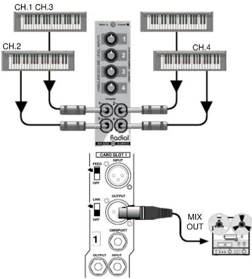
Using the Submix will be mostly the same no matter what source is connected so we have decided to use keyboards as the source to explain the functionality. Start by connecting the output from your first keyboard to input-1 on the Submix. You will note that the noise level will remain low at all levels. The Submix employs Radial's unique VaryState™ gain control that actually changes the sensitivity along with the gain. Set the level control completely counterclockwise or off to start. Connect the output from the rear panel of your 500 series power rack to your recording system. Start playing increase the level slowly until you reach a comfortable listening level. Repeat for input-2.
flowchart
graph TD
    subgraph_Channel_1["CH.1 CH.3"]
        A1["Ch.1"] --> B1["Ch.2"]
        A2["Ch.2"] --> B2["Ch.3"]
        A3["Ch.3"] --> B3["Ch.4"]
    end
    subgraph_Channel_2["CH.4"]
        C1["CH.4"] --> D1["Ch.5"]
        C2["Ch.5"] --> D2["Ch.6"]
        C3["Ch.6"] --> D3["Ch.7"]
    end
    subgraph_Card_Slot1["Card Slot 1"]
        E1["FEED"] --> F1["INPUT"]
        F1 --> G1["OFF"]
        G1 --> H1["LINK"]
        H1 --> I1["OUTPUT"]
        I1 --> J1["OFF"]
        J1 --> K1["OMNIPORT"]
        K1 --> L1["OUTPUT"]
        L1 --> M1["INPUT"]
    end
    N["MIX OUT"] --> O["Mixer"]
Connecting four mono instruments to the Submix
COMBINING SUBMIX MODULES TOGETHER FOR MORE CHANNELS
If you are equipped with a Radial Workhorse power rack, you can combine two or more Submix modules together to create larger mixers. Simply connect the TRS output from the first unit and plug it into the Omniport and the signal will automatically appear on the output buss to create an 8x1 mixer. Adding a third Submix will give you a 12x1 mixer. Combine these with a Workhorse Powerstrip, to can create a super compact 12x1 stage mixer!

flowchart
graph TD
    subgraph KEYBOARDS_1~4["KEYBOARDS 1~4"]
        A1["Input"] --> B1["UNIAPART RED INPUT"]
        A2["Input"] --> B2["UNIAPART RED INPUT"]
        A3["Input"] --> B3["UNIAPART RED INPUT"]
        A4["Input"] --> B4["UNIAPART RED INPUT"]
        A5["Input"] --> B5["UNIAPART RED INPUT"]
        A6["Input"] --> B6["UNIAPART RED INPUT"]
        A7["Input"] --> B7["UNIAPART RED INPUT"]
        A8["Input"] --> B8["UNIAPART RED INPUT"]
        A9["Input"] --> B9["UNIAPART RED INPUT"]
        A10["Input"] --> B10["UNIAPART RED INPUT"]
        A11["Input"] --> B11["UNIAPART RED INPUT"]
        A12["Input"] --> B12["UNIAPART RED INPUT"]
        A13["Input"] --> B13["UNIAPART RED INPUT"]
        A14["Input"] --> B14["UNIAPART RED INPUT"]
        A15["Input"] --> B15["UNIAPART RED INPUT"]
        A16["Input"] --> B16["UNIAPART RED INPUT"]
        A17["Input"] --> B17["UNIAPART RED INPUT"]
        A18["Input"] --> B18["UNIAPART RED INPUT"]
        A19["Input"] --> B19["UNIAPART RED INPUT"]
        A20["Input"] --> B20["UNIAPART RED INPUT"]
        A21["Input"] --> B21["UNIAPART RED INPUT"]
        A22["Input"] --> B22["UNIAPART RED INPUT"]
        A23["Input"] --> B23["UNIAPART RED INPUT"]
        A24["Input"] --> B24["UNIAPART RED INPUT"]
        A25["Input"] --> B25["UNIAPART RED INPUT"]
        A26["Input"] --> B26["UNIAPART RED INPUT"]
        A27["Input"] --> B27["UNIAPART RED INPUT"]
        A28["Input"] --> B28["UNIAPART RED INPUT"]
        A29["Input"] --> B29["UNIAPART RED INPUT"]
        A30["Input"] --> B30["UNIAPART RED INPUT"]
        A31["Input"] --> B31["UNIAPART RED INPUT"]
        A32["Input"] --> B32["UNIAPART RED INPUT"]
        A33["Input"] --> B33["UNIAPART RED INPUT"]
        A34["Input"] --> B34["UNIAPART RED INPUT"]
        A35["Input"] --> B35["UNIAPART RED INPUT"]
        A36["Input"] --> B36["UNIAPART RED INPUT"]
        A37["Input"] --> B37["UNIAPART RED INPUT"]
        A38["Input"] --> B38["UNIAPART RED INPUT"]
        A39["Input"] --> B39["UNIAPART RED INPUT"]
        A40["Input"] --> B40["UNIAPART RED INPUT"]
        A41["Input"] --> B41["UNIAPART RED INPUT"]
        A42["Input"] --> B42["UNIAPART RED INPUT"]
        A43["Input"] --> B43["UNIAPART RED INPUT"]
        A44["Input"] --> B44["UNIAPART RED INPUT"]
        A45["Input"] --> B45["UNIAPART RED INPUT"]
        A46["Input"] --> B46["UNIAPART RED INPUT"]
        A47["Input"] --> B47["UNIAPART RED INPUT"]
        A48["Input"] --> B48["UNIAPART RED INPUT"]
        A49["Input"] --> B49["UNIAPART RED INPUT"]
        A50["Input"] --> B50["UNIAPART RED INPUT"]
        A51["Input"] --> B51["UNIAPART RED INPUT"]
        A52["Input"] --> B52["UNIAPART RED INPUT"]
        A53["Input"] --> B53["UNIAPART RED INPUT"]
        A54["Input"] --> B54["UNIAPART RED INPUT"]
        A55["Input"] --> B55["UNIAPART RED INPUT"]
        A56["Input"] --> B56["UNIAPART RED INPUT"]
        A57["Input"] --> B57["UNIAPART RED INPUT"]
        A58["Input"] --> B58["UNIAPART RED INPUT"]
        A59["Input"] --> B59["UNIAPART RED INPUT"]
        A60["Input"] --> B60["UNIAPART RED INPUT"]
        A61["Input"] --> B61["UNIAPART RED INPUT"]
        A62["Input"] --> B62["UNIAPART RED INPUT"]
        A63["Input"] --> B63["UNIAPART RED INPUT"]
        A64["Input"] --> B64["UNIAPART RED INPUT"]
        A65["Input"] --> B65["UNIAPART RED INPUT"]
        A66["Input"] --> B66["UNIAPART RED INPUT"]
        A67["Input"] --> B67["UNIAPART RED INPUT"]
        A68["Input"] --> B68["UNIAPART RED INPUT"]
        A69["Input"] --> B69["UNIAPART RED INPUT"]
        A70["Input"] --> B70["UNIAPART RED INPUT"]
        A71["MIX 1~4 OUT"] -->|MIX 1~4 OUT| MUXOUT
    end
    subgraph CARD_SLOT_1
            direction TB
            NFEED
            OFF
            LINK
            OUTPUT
            OFF
            OMNIPORT
            OUTPUT
            OUTPUT
    end
    subgraph CARD_SLOT_1
            direction LR
            NFEED
            OFF
            LINK
            OUTPUT
            OFF
            OMNIPORT
            OUTPUT
    end
    subgraph OMNI_PORT_IN
            direction IN
            OUTFOUT
            OUTPUT
            OUTPUT
    end
    subgraph MIX_OUT_1
            direction OUT
            OUTFOUT
            OUTPUT
            OUTPUT
    end
Two Submix modules tied together via Omniport configured for 8x1 mono output
COMBINING SUBMIX MODULES TOGETHER FOR STEREO
With two Submix modules, you can create a stereo setup by assigning the first Submix to left and the second Submix to right. When connecting, simply split the stereo signals to follow suit and you are set to go. This can provide your studio with a very efficient way of managing stereo sources such as playback tracks for overdubbing, mixing four stereo keyboards, or even be used to sum effects or channels together.

flowchart
graph TD
    A["User Interface"] -->|KEYBOARDS LEFT| B["Keyboard Left"]
    A -->|KEYBOARDS RIGHT| C["Keyboard Right"]
    B --> D["Card Slot 1 INPUT"]
    B --> E["MIX 1~4 OUT"]
    C --> F["Card Slot 1 INPUT"]
    C --> G["MIX 5~8 OUT"]
    D --> H["OUTPUT LINK"]
    E --> I["OUTPUT LINK"]
    F --> J["OUTPUT LINK"]
    G --> K["OUTPUT LINK"]
    H --> L["UNBALANCED LINE INPUTS"]
    I --> M["UNBALANCED LINE INPUTS"]
    J --> N["UNBALANCED LINE INPUTS"]
    K --> O["UNBALANCED LINE INPUTS"]
    style A fill:#f9f,stroke:#333
    style B fill:#ccf,stroke:#333
    style C fill:#ccf,stroke:#333
    style D fill:#dfd,stroke:#333
    style E fill:#dfd,stroke:#333
    style F fill:#dfd,stroke:#333
    style G fill:#dfd,stroke:#333
    style H fill:#dfd,stroke:#333
    style I fill:#dfd,stroke:#333
    style J fill:#dfd,stroke:#333
    style K fill:#dfd,stroke:#333
    style L fill:#dfd,stroke:#333
Two Submix modules configured 8x2 stereo output
RADIAL SUBMIX 500 SPECIFICATIONS
Circuit Type.....High grade audio IC op-amps with Accustate gain control
Frequency response .....20 Hz to 20KHz (+/- 0.5 dB)
Phase Response ....<10 degree shift at 20KHz
Maximum Input ....-2dBu/+12dBu
Maximum Output ....+16dBu
THD + N ....<0.005% (at 0dBu output)
Dynamic range 97dB (maximum input - noise floor)
Equivalent input noise ......-103dBu (maximum gain - noise floor)
Noise ....-85dBu (at maximum gain)
Gain ....+18dB (at maximum gain)
Intermodulation Distortion.....<0.006% (at 0dBu output)
Input Impedance ....100K (unbalanced)
Output Impedance ....300 Ohms
Omniport Function ....Unity gain expansion buss input
Power requirement ....+/- 16V (Workhorse or 500 series compatible power frame
Current draw 31mA
XLR Configuration:....Follows AES spec: pin-1 ground, pin-2 hot (+), pin-3 cold (-)
Size: 5.25" x 1.5" x 6.6" (13.34 x 3.81 x 16.75cm)
Weight: 0.7 lb (316 g)
Warranty: 3 years, transferable
THREE YEAR TRANSFERABLE LIMITED WARRANTY
RADIAL ENGINEERING LTD. ("Radial") warrants this product to be free from defects in material and workmanship and will remedy any such defects free of charge according to the terms of this warranty. Radial will repair or replace (at its option) any defective component(s) of this product (excluding finish and wear and tear on components under normal use) for a period of three (3) years from the original date of purchase. In the event that a particular product is no longer available, Radial reserves the right to replace the product with a similar product of equal or greater value. In the unlikely event that a defect is uncovered, please call 604-942-1001 or email service@radialeng.com to obtain an RA number (Return Authorization number) before the 3 year warranty period expires. The product must be returned prepaid in the original shipping container (or equivalent) to Radial or to an authorized Radial repair center and you must assume the risk of loss or damage. A copy of the original invoice showing date of purchase and the dealer name must accompany any request for work to be performed under this limited and transferable warranty. This warranty shall not apply if the product has been damaged due to abuse, misuse, misapplication, accident or as a result of service or modification by any other than an authorized Radial repair center.
THERE ARE NO EXPRESSED WARRANTIES OTHER THAN THOSE ON THE FACE HEREOF AND DESCRIBED ABOVE. NO WARRANTIES WHETHER EXPRESSED OR IMPLIED, INCLUDING BUT NOT LIMITED TO, ANY IMPLIED WARRANTIES OF MERCHANTABILITY OR FITNESS FOR A PARTICULAR PURPOSE SHALL EXTEND BEYOND THE RESPECTIVE WARRANTY PERIOD DESCRIBED ABOVE OF THREE YEARS. RADIAL SHALL NOT BE RESPONSIBLE OR LIABLE FOR ANY SPECIAL, INCIDENTAL OR CONSEQUENTIAL DAMAGES OR LOSS ARISING FROM THE USE OF THIS PRODUCT. THIS WARRANTY GIVES YOU SPECIFIC LEGAL RIGHTS, AND YOU MAY ALSO HAVE OTHER RIGHTS, WHICH MAY VARY DEPENDING ON WHERE YOU LIVE AND WHERE THE PRODUCT WAS PURCHASED.

This product is intended for professional use only. The user should be familiar and experienced with the 500 series rack and module format.

Radial Engineering Ltd.
1588 Kebet Way, Port Coquitlam, BC, V3C 5M5
tel: 604-942-1001 • fax: 604-942-1010
info@radialeng.com • www.radialeng.com



- Table of Contents Page
- WARNING NOTICE TO USER!
- OVERVIEW
- FEATURE SET
- GETTING STARTED
- Making connections
- Omniport
- USING THE SUBMIX IN MONO
- COMBINING SUBMIX MODULES TOGETHER FOR MORE CHANNELS
- COMBINING SUBMIX MODULES TOGETHER FOR STEREO
- RADIAL SUBMIX 500 SPECIFICATIONS
- THREE YEAR TRANSFERABLE LIMITED WARRANTY
Brand : Radial Engineering
Model : SubMix
Category : Professional audio equipment