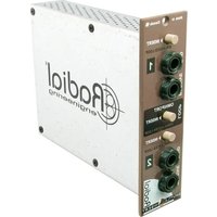
Workhorse Shuttle - Professional audio equipment Radial Engineering - Free user manual and instructions
Find the device manual for free Workhorse Shuttle Radial Engineering in PDF.


| Product Type | 500 Series Patch Point Module |
| Compatibility | Standard 500 series racks and Radial Workhorse |
| Number of Loops | 3 (Loop-1 balanced, Loop-2 unbalanced, Omniport insert) |
| Loop-1 Connectors | Balanced +4dB SEND & RECEIVE (TRS jacks) |
| Loop-2 Connectors | Unbalanced -10dB SEND & RECEIVE (1/4" TS jacks) |
| Omniport Connector | TRS unbalanced insert (Tip Send, Ring Return) – available with Workhorse |
| Insert Switches | Loop-1, Loop-2, and Omniport front panel switches for A/B comparison |
| Gain | 0 dB (unity) |
| Frequency Response | 20 Hz to 20 kHz (±0.5 dB) |
| Dynamic Range | >130 dB |
| Input Impedance | 20 kΩ (balanced) |
| Output Impedance | 0 Ω (rear XLR direct from input) |
| Clip Level (Input) | +22 dBu (Workhorse mix buss) |
| Clip Level (Output) | >+25 dBu |
| Noise | < -125 dBu |
| Power Requirement | 5 mA (from 500 series rack) |
| Weight | 1.5 lbs (0.7 kg) |
| Dimensions (H x W x D) | 5.25" x 1.5" x 6.5" (standard 500 series module) |
| Warranty | 3 years, transferable |
| Cleaning | Wipe with dry cloth; no solvents |
Frequently Asked Questions - Workhorse Shuttle Radial Engineering
User questions about Workhorse Shuttle Radial Engineering
0 question about this device. Answer the ones you know or ask your own.
Ask a new question about this device
Download the instructions for your Professional audio equipment in PDF format for free! Find your manual Workhorse Shuttle - Radial Engineering and take your electronic device back in hand. On this page are published all the documents necessary for the use of your device. Workhorse Shuttle by Radial Engineering.
USER MANUAL Workhorse Shuttle Radial Engineering
Table of Contents Page
Feature Set 1
Overview 2
Getting Started 3
Using the Loops 4
Omniport 6
Patching External Sources 8
Specifications 9
Block Diagram 9
Warranty......Back cover
Congratulations and thank you for your purchase of the Radial Shuttle 500 module. The Shuttle is a simple yet highly effective tool that will help you efficiently route signals in and out of your Workhorse or 500 series rack. In fact, it is probably one of those devices that you will soon come to say: "I wonder how I could have lived without it?"
To help you get there, we have written this short manual. Please take a few minutes to read it through so that you can take full advantage of the features that are built in. Hopefully, we have addressed all of your concerns. If however you do not find all of the answers and wisdom as you drop your bucket into the deep well of recording knowledge, visit the FAQ page on our web site. This is where we post questions from users like you along with helpful hints. If you do not find what you are looking for, then send us an email at info@radialeng.com. We will do our very best to answer your question in short order.
Get ready to plug in, out and in between!
FEATURE SET
- LOOP-1 INSERT SWITCH: Inserts the balanced loop into the signal path to compare pre and post signals. Works with all 500 series modules and racks.
- LOOP-1 SEND & RECEIVE JACKS: Line-level +4dB loop connects to pro-audio processors with separate balanced send and receive TRS jacks. Works with all 500 series modules and racks.
- OMNIPORT INSERT LOOP SWITCH: Inserts the Omniport loop into the signal path to compare pre and post signals. Available when used with the Radial Workhorse.
- LOOP-2 INSERT SWITCH: Inserts the unbalanced loop into the signal path to compare pre and post signals. Available when used with the Radial Workhorse.
- LOOP-2 SEND & RECEIVE JACKS: Line-level -10dB loop connects to unbalanced devices with separate 1/4" phone jacks. Available when used with the Radial Workhorse.
- OMNIPORT (Workhorse): TRS type unbalanced insert jack confi gured TIP=SEND; RING=RETURN. Available when used with the Radial Workhorse.

OVERVIEW
The Radial Shuttle is a patch point module that enables you to bring signals in and out of the Radial Workhorse and other 500 series modules. Think of it as a convenience device. In other words, it enables you to perform a number of functions via front panel connectors that otherwise would require rear panel patching or re-routing. Some of the functions the Shuttle enables include playback routing for overdubbing, direct input from music players or other audio sources, effects routing and for those with a Workhorse, easier integration of older 500 series modules and rear panel connectivity to a remote patch bay.
Shuttle Used In Older 500 Series Racks
When the Shuttle is used in a non-Radial 500 series rack LOOP-1 is available through the balanced input and output. LOOP-2 will also deliver an unbalanced signal via the Shuttle front panel SEND jack.

flowchart
graph TD
    A["Card Slot XLR Input"] --> B["Balanced Loop-1"]
    B --> C["Card Slot XLR Output"]
    B --> D["Balanced Audio Device"]
    D --> B
Shuttle Used In Radial Workhorse 500 Series Racks
When the Shuttle is used in a Radial Workhorse 500 series rack LOOP-1 is available through the balanced input and output. LOOP-2 and the Omniport insert are also available and routed to the Workhorse internal MIX BUSS and mixer section.

flowchart
graph TD
    A["Card Slot XLR Input"] --> B["Balanced Loop-1"]
    B --> C["Card Slot XLR Output"]
    B --> D["Unbalanced Loop-2"]
    D --> E["Omniport Insert Loop"]
    E --> F["Workhorse Mixer"]
    F --> G["Balanced XLR Output"]
    B --> H["Balanced Audio Device"]
    D --> I["Unbalanced Audio Device"]
    E --> J["Unbalanced Audio Device"]
GETTING STARTED
Before making any connections, start by turning off your audio system and turning all volume levels down. This helps protect equipment from turn-on transients that could damage loudspeakers and other sensitive equipment. We recommend using a power bar with an on-off switch as this makes it easy to turn on and off the 500 series rack, monitors and so on, using a single switch. Carefully plug the Shuttle into your 500 series rack to avoid stress on the card edge connector. Screw the module in to ensure it does not accidentally become dislodged.
Most 500 series racks are equipped with XLR connectors. When you plug the Shuttle into your 500 series rack, it will automatically route the input and output to the module. With the Workhorse, this is augmented with 14 TRS connectors, D-Subs and a signal to feed the Workhorse mixer. It also activates the Omniport which in this instance turns the Omniport into an unbalanced TRS type insert.
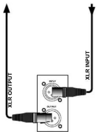
500 SERIES RACK WORKHORSE RACK

XLR & TRS I/O
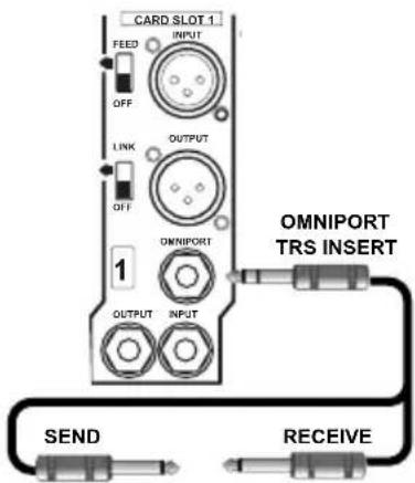
WORKHORSE RACK OMNIPORT I/O
USING THE LOOPS
The Shuttle can be used in any standard 500 series rack. There are some added features that Workhorse users can enjoy. The easiest way to discover the Shuttle's functionality is to go right to applications. This way, you can determine a need and then connect the Shuttle to address it.
Balanced Patch Point
Professional level (+4dB) balanced studio devices are usually much quieter than unbalanced devices and thus preferred by recording engineers. Often, particular processors will be brought into the studio for special effects or maybe mastering. Patching these into a studio setup usually requires pulling racks apart, disconnecting cables and so on.
The Shuttle makes this process easy by allowing you to connect the output from your workstation or other 500 series module to the XLR inputs on the Shuttle (via your 500 series rack or via the FEED switch on the Workhorse) and then using the 1/4 TRS connectors on the front panel to route the signal to and from the effect. The Shuttle's output can then be sent back to your workstation or to the Workhorse mixer. Use the insert switch to turn on or off the effect for quick comparisons between the wet and dry signals.

flowchart
graph TD
    A["Audio Unit"] -->|Signal| B["Decer"]
    B --> C["Antenna"]
    C --> D["Radio Unit"]
    D --> E["Antenna"]
    style A fill:#f9f,stroke:#333
    style B fill:#bbf,stroke:#333
    style C fill:#bfb,stroke:#333
    style D fill:#ffb,stroke:#333
    style E fill:#cfc,stroke:#333
BALANCED PATCH POINT USED IN AN OLDER 500 SERIES RACK

flowchart
graph TD
    A["Radio"] -->|MIX BUSS| B["Workhorse Mixer"]
    B --> C["Audio & Computer"]
    A --> D["Radio"]
    D --> E["Radio"]
    style A fill:#f9f,stroke:#333
    style B fill:#ccf,stroke:#333
    style C fill:#cfc,stroke:#333
BALANCED PATCH POINT USED IN THE RADIAL WORKHORSE RACK

14 " TRS PHONE to XLR BALANCED WIRE DIAGRAM

14 " PHONE to XLR UNBALANCED WIRE DIAGRAM
Unbalanced Patch Point
For those equipped with a Workhorse 500 series rack, a second loop is available via front panel 14 " unbalanced SEND and RECEIVE jacks. The most common method of routing effects in the studio is via an unbalanced effects insert. This of course is common to all recording consoles, but is not always convenient with today's digital recording workstations. The Shuttle brings the convenience of front panel patching to your Workhorse.
Connect the source signal to the Shuttle via the Workhorse and the signal will automatically be routed to the LOOP-2 front panel 14 ” connectors. The Shuttle is equipped with internal buffers that will properly unbalance the signal so that your effect device will get the proper level and impedance. Use standard guitar type 14 ” cables to route the signal to and from your effect device. Once the signal is received back into the Shuttle it is routed to the internal mix buss and the Workhorse mixer section. The front panel on-off switch lets you bypass the loop so you can compare the wet and dry signals.

flowchart
graph TD
    A["Radio Receiver"] -->|MIX BUSS| B["Radio Mixer"]
    B --> C["Audio Recorder"]
    D["Radio Receiver"] -->|WORKHORSE MIXER| E["Radio Mixer"]
    E --> F["Audio Recorder"]
    style A fill:#f9f,stroke:#333
    style B fill:#ccf,stroke:#333
    style C fill:#cfc,stroke:#333
    style D fill:#fcc,stroke:#333
    style E fill:#cff,stroke:#333
UNBALANCED PATCH POINT USED IN THE RADIAL WORKHORSE RACK


14 " PHONE to 14 " PHONE UNBALANCED WIRE DIAGRAM
Omniport Insert Patch Point
For those equipped with a Workhorse, a third loop is available via the Omniport connector. This 14 " TRS connector follows the standard tip-send, ring-return and is ideally suited for routing signals to a favorite effects device such as a limiter or to a remote patchbay. This sends an unbalanced signal to the effects device and returns the wet signal using the same cable.

THE OMNIPORT FEATURE IS ACCESSED ON THE REAR PANEL OF THE WORKHORSE RACK.
The Omniport Insert is wired in series with loop one and two. This enables you to combine as many as three loops together in series to create dramatic effects. And as with the other two loops, you can engage the insert loop using the front panel switch or turn it off to compare the wet and dry signals.

flowchart
graph LR
    A["Balanced Input"] --> B["Balanced Loop-1"]
    B --> C["Unbalanced Loop-2"]
    C --> D["Omniport Insert Loop"]
    D --> E["Workhorse Mixer"]
    B --> F["Balanced Audio Device"]
    C --> G["Unbalanced Audio Device"]
    D --> H["Unbalanced Audio Device"]
Using The Shuttle With Non-Radial Modules And The Workhorse
Each card-slot in the Workhorse rack is equipped with a function called FEED that essentially replaces an XLR cable. This routes the signal from one module into the next to enable the engineer to set up elaborate channel strips or crazy effects. Because the FEED function frees up the XLR connectors these can still be used for even more elaborate routing or for sending dry tracks back to the recording system for later Reamping™.

flowchart
graph TD
    A["FEED"] --> B["CARD SLOT 1 INPUT"]
    B --> C["OUTPUT"]
    C --> D["LINK"]
    D --> E["OUTPUT"]
    E --> F["FEED"]
    F --> G["CARD SLOT 1 OUTPUT"]
    G --> H["OUTPUT"]
    H --> I["OUTPUT"]
    I --> J["FEED"]
    J --> K["CARD SLOT 1 INPUT"]
    K --> L["OUTPUT"]
    L --> M["OUTPUT"]
As soon as you plug in your module, the FEED function will route the signal through the Shuttle, onto the Workhorse internal buss and into the mixer section. This enables the engineer to take full advantage of the Workhorse mixer without having to patch the signal via the D-SUB summing mixer input. To use the FEED function simply install the Shuttle in a card-slot to the right of the older 500 module, engage the FEED switch on the Workhorse and you are set to go.
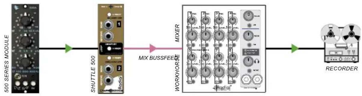
flowchart
graph LR
    A["500 SERIES MODULE"] --> B["SHUTTLE 500"]
    B --> C["MIX BUSSFEEE"]
    C --> D["WORKHORSE"]
    D --> E["RECORDER"]
Overdubbing Using The Workhorse
A common concern when using digital workstations is latency. This is a delay caused by the time it takes the recording system to process the new track and combine it with the existing track. Although this is getting better, for some, latency causes a sense of detachment. Thus most prefer to record in the analogue domain.
The Workhorse mixer and Shuttle module can be configured to provide a monitor mix while recording overdubs. For instance, when overdubbing a vocal track you send a pre-recorded mix of tracks from your workstation and connect it to the Shuttle's input (two Shuttles are used for stereo). The Shuttle routes the workstation playback signal to the Workhorse mixer where it is mixed with the signals from one or more microphone preamps like the Radial PowerPre™. You can use the mixer channel controls to quickly set up and adjust a monitor mix. Headphones can be connected directly or you could use the mixer's balanced outputs to drive an amplifier and power several sets of headphones. To record the overdub track the output from the mic preamp is sent directly to your recording system via the card slot I/O.

flowchart
graph TD
    A["SHUTTLE 500"] -->|MIX BUSS| B["POWERPRE 500"]
    B -->|MIX BUSS| C["WORKHORSE MIXER"]
    C -->|MONITOR OUTPUT| D["MONITOR OUTPUT"]
    D --> E["MONITOR OUTPUT"]
    E --> F["MONITOR OUTPUT"]
    F --> G["MONITOR OUTPUT"]
    G --> H["MONITOR OUTPUT"]
    H --> I["MONITOR OUTPUT"]
    I --> J["MONITOR OUTPUT"]
    J --> K["MONITOR OUTPUT"]
    K --> L["MONITOR OUTPUT"]
    L --> M["MONITOR OUTPUT"]
    M --> N["MONITOR OUTPUT"]
    N --> O["MONITOR OUTPUT"]
    O --> P["MONITOR OUTPUT"]
    P --> Q["MONITOR OUTPUT"]
    Q --> R["MONITOR OUTPUT"]
    R --> S["MONITOR OUTPUT"]
    S --> T["MONITOR OUTPUT"]
    T --> U["MONITOR OUTPUT"]
    U --> V["MONITOR OUTPUT"]
    V --> W["MONITOR OUTPUT"]
    W --> X["MONITOR OUTPUT"]
    X --> Y["MONITOR OUTPUT"]
    Y --> Z["MONITOR OUTPUT"]
    Z --> AA["MONITOR OUTPUT"]
    AA --> AB["MONITOR OUTPUT"]
    AB --> AC["MONITOR OUTPUT"]
    AC --> AD["MONITOR OUTPUT"]
    AD --> AE["MONITOR OUTPUT"]
    AE --> AF["MONITOR OUTPUT"]
    AF --> AG["MONITOR OUTPUT"]
    AG --> AH["MONITOR OUTPUT"]
    AH --> AI["MONITOR OUTPUT"]
    AI --> AJ["MONITOR OUTPUT"]
    AJ --> AK["MONITOR OUTPUT"]
    AK --> AL["MONITOR OUTPUT"]
    AL --> AM["MONITOR OUTPUT"]
    AM --> AN["MONITOR OUTPUT"]
    AN --> AO["MONITOR OUTPUT"]
    AO --> AP["MONITOR OUTPUT"]
    AP --> AQ["MONITOR OUTPUT"]
    AQ --> AR["MONITOR OUTPUT"]
    AR --> AS["MONITOR OUTPUT"]
    AS --> AT["MONITOR OUTPUT"]
    AT --> AU["MONITOR OUTPUT"]
    AU --> AV["MONITOR OUTPUT"]
    AV --> AW["MONITOR OUTPUT"]
    AW --> AX["MONITOR OUTPUT"]
    AX --> AY["MONITOR OUTPUT"]
    AY --> AZ["MONITOR OUTPUT"]
    AZ --> BA["MONITOR OUTPUT"]
    BA --> BB["MONITOR OUTPUT"]
    BB --> BC["MONITOR OUTPUT"]
    BC --> BD["MONITOR OUTPUT"]
    BD --> BE["MONITOR OUTPUT"]
    BE --> BF["MONITOR OUTPUT"]
    BF --> BG["MONITOR OUTPUT"]
    BG --> BH["MONITOR OUTPUT"]
    BH --> BI["MONITOR OUTPUT"]
    BI --> BJ["MONITOR OUTPUT"]
    BJ --> BK["MONITOR OUTPUT"]
    BK --> BL["MONITOR OUTPUT"]
    BL --> BM["MONITOR OUTPUT"]
    BM --> BN["MONITOR OUTPUT"]
Patching External Sources
The Shuttle's two front panel loops are capable of being used as secondary (alternate) inputs to enable line-level sources such as keyboards, CD players, DJ mixers or drum machines to easily connect to the Workhorse mixer section and directly to your workstation. The routing options are different depending on which loop you connect to.
Loop-1
Patching into Loop-1, for instance, will route an external signal to the card slot's rear panel balanced XLR output. If the Shuttle is installed in a Workhorse the signal is also routed to the mixer section via the mix buss. Use the LOOP-1 INSERT switch to turn the external signal on and off.

flowchart
graph LR
    A["PRO-AUDIO DEVICE (BALANCED OR UNBALANCED)"] --> B["SHUTTLE 500"]
    B --> C["REAR PANEL I/O"]
    C --> D["RECORDER"]
    D --> E["MIXER"]
    E --> F["WORKHORSE"]
    style A fill:#f9f,stroke:#333
    style B fill:#ccf,stroke:#333
    style C fill:#cfc,stroke:#333
    style D fill:#fcc,stroke:#333
    style E fill:#cff,stroke:#333
    style F fill:#ffc,stroke:#333
Loop-2
Patching into LOOP-2 will route an external signal directly to the mixer section via the Workhorse mix buss. From there, the signal may be routed to the mixer's MAIN and MONITOR outputs to connect a balanced +4dB signal back to your workstation or you can simply monitor with headphones right from the mixer front panel. You can use the LOOP-2 INSERT switch or the mixer channel ON switch to turn the external signal on and off.

flowchart
graph LR
    A["MUSIC PLAYER (UNBALANCED)"] --> B["SHUTTLE 500"]
    B --> C["RECORDER"]
    C --> D["WORKHORSE"]
    D --> E["MIX BUSS"]
    E --> C
SHUTTLE 500 MODULE SPECIFICATIONS\*
Clip Level - Input +22dbu (Workhorse mix buss)
Clip Level - Output >+25dbu
Dynamic Range >130dB
Frequency Response 20Hz to 20KHz (+/- 0.5dB)
Gain 0db
Input Impedance 20K Ohms (Balanced)
Noise <-125dbu
Omniport Function Unbalanced insert loop
Output Impedance 0.0 Ohms (Rear panel XLR, direct connection from Input)
Power Requirement 5mA
Shipping Weight 1.5 lbs (0.7kg)
Warranty 3 Years
CONNECTOR WIRING
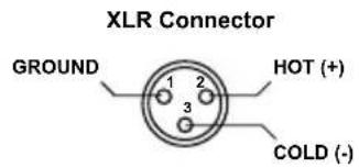

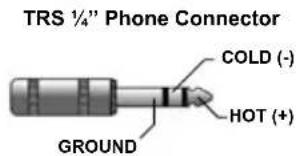
BLOCK DIAGRAM\*

flowchart
graph TD
    A["XLR INPUT"] --> B["+"]
    B --> C["SEND"]
    C --> D["BALANCED LOOP"]
    D --> E["LOOP-1 INSERT"]
    E --> F["+"]
    F --> G["BALANCED TO UNBALANCED CONVERTER"]
    G --> H["LOOP-2 INSERT"]
    H --> I["SEND"]
    I --> J["UNBALANCED LOOP"]
    J --> K["MIX BUSS"]
    K --> L["4.7K"]
    L --> M["BUFFER"]
    M --> N[" Omniport INSERT "]
    N --> O["Receive"]
    O --> P[" Omniport LOOP"]
    P --> Q["SEND"]
    Q --> R["Receive"]
THREE YEAR TRANSFERABLE LIMITED WARRANTY
RADIAL ENGINEERING LTD. ("Radial") warrants this product to be free from defects in material and workmanship and will remedy any such defects free of charge according to the terms of this warranty. Radial will repair or replace (at its option) any defective component(s) of this product (excluding finish and wear and tear on components under normal use) for a period of three (3) years from the original date of purchase. In the event that a particular product is no longer available, Radial reserves the right to replace the product with a similar product of equal or greater value. In the unlikely event that a defect is uncovered, please call 604-942-1001 or email service@radialeng.com to obtain an RA number (Return Authorization number) before the 3 year warranty period expires. The product must be returned prepaid in the original shipping container (or equivalent) to Radial or to an authorized Radial repair centre and you must assume the risk of loss or damage. A copy of the original invoice showing date of purchase and the dealer name must accompany any request for work to be performed under this limited and transferable warranty. This warranty shall not apply if the product has been damaged due to abuse, misuse, misapplication, accident or as a result of service or modification by any other than an authorized Radial repair centre.
THERE ARE NO EXPRESSED WARRANTIES OTHER THAN THOSE ON THE FACE HEREOF AND DESCRIBED ABOVE. NO WARRANTIES WHETHER EXPRESSED OR IMPLIED, INCLUDING BUT NOT LIMITED TO, ANY IMPLIED WARRANTIES OF MERCHANTABILITY OR FITNESS FOR A PARTICULAR PURPOSE SHALL EXTEND BEYOND THE RESPECTIVE WARRANTY PERIOD DESCRIBED ABOVE OF THREE YEARS. RADIAL SHALL NOT BE RESPONSIBLE OR LIABLE FOR ANY SPECIAL, INCIDENTAL OR CONSEQUENTIAL DAMAGES OR LOSS ARISING FROM THE USE OF THIS PRODUCT. THIS WARRANTY GIVES YOU SPECIFIC LEGAL RIGHTS, AND YOU MAY ALSO HAVE OTHER RIGHTS, WHICH MAY VARY DEPENDING ON WHERE YOU LIVE AND WHERE THE PRODUCT WAS PURCHASED.

This product is intended for professional use only. The user should be familiar and experienced with the 500 series rack and module format

True to the Music
Radial Engineering Ltd. 1588 Kebet Way, Port Coquitlam, British Columbia, V3C 5M5 tel: 604-942-1001 • fax: 604-942-1010 • email: info@radialeng.com
www.radialeng.com
Reamp, Reamper, Reamping and Workhorse are trademarks of Radial Engineering Ltd. Copyright 2011 Radial Engineering Ltd. All rights reserved. Specifications and appearances subject to change without notice. Radial® Shuttle™ 500 Module User Guide Rev1.0 April 2011 - Part #: R870 1252 00 Printed in Canada



- Table of Contents Page
- FEATURE SET
- OVERVIEW
- Shuttle Used In Older 500 Series Racks
- Shuttle Used In Radial Workhorse 500 Series Racks
- GETTING STARTED
- USING THE LOOPS
- Balanced Patch Point
- Unbalanced Patch Point
- Omniport Insert Patch Point
- Using The Shuttle With Non-Radial Modules And The Workhorse
- Overdubbing Using The Workhorse
- Patching External Sources
- Loop-1
- Loop-2
- SHUTTLE 500 MODULE SPECIFICATIONS\*
- CONNECTOR WIRING
- BLOCK DIAGRAM\*
- THREE YEAR TRANSFERABLE LIMITED WARRANTY
- www.radialeng.com
Brand : Radial Engineering
Model : Workhorse Shuttle
Category : Professional audio equipment