
FC1420 - Network card / adapter TP-LINK - Free user manual and instructions
Find the device manual for free FC1420 TP-LINK in PDF.
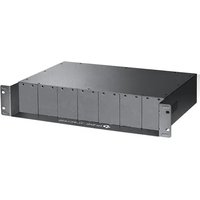


| Product Type | Media Converter Module (for 14-slot rackmount chassis) |
| Model | FC1420 |
| Brand | TP-Link |
| Chassis Compatibility | TL-MC1400 14-slot rackmount chassis |
| Power Output per Slot | 5 V / 0.6 A |
| Dimensions (W × D × H) | 482 × 309 × 86 mm (chassis) |
| Operating Temperature | 0°C to 50°C (32°F to 122°F) |
| Storage Temperature | -40°C to 70°C (-40°F to 158°F) |
| Operating Humidity | 10% to 90% RH non-condensing |
| Storage Humidity | 5% to 90% RH non-condensing |
| Input AC Power Supply | 100-240 V ~ 50/60 Hz 1.8 A Max |
| Output DC Power Supply | 12 V, 6.25 A Max |
| Ripple & Noise | < 180 mV (0°C to 50°C); < 250 mV (-10°C to 0°C) |
| Power LED | On: Power on; Off: Power off |
| Fan LED | On: Fans working properly; Off: Fans abnormal |
| Hot-swappable | Yes |
| Overload Protection | Yes |
| Mounting | 19-inch rack (EIA standard) |
| Package Contents | Chassis, AC Power Cord, Fourteen Retainer-plates, Installation Guide |
| Safety Compliance | FCC Class A, CE, ICES-3 (A), BSMI |
| Warranty | Refer to TP-Link warranty policy |
Frequently Asked Questions - FC1420 TP-LINK
User questions about FC1420 TP-LINK
0 question about this device. Answer the ones you know or ask your own.
Ask a new question about this device
Download the instructions for your Network card / adapter in PDF format for free! Find your manual FC1420 - TP-LINK and take your electronic device back in hand. On this page are published all the documents necessary for the use of your device. FC1420 by TP-LINK.
USER MANUAL FC1420 TP-LINK
To ask questions, find answers, and communicate with TP-Link users or engineers, please visit https://community.tp-link.com to join TP-Link Community. For technical support and other information, please visit https://www.tp-link.com/support, or simply scan the QR code.

© 2022 TP-Link 7106509905 REV3.2.2
Package Contents: Chassis, AC Power Cord, Fourteen Retainer-plates, Installation Guide
The pictures are for demonstration purposes only. The actual product may differ in appearance from the depicted.
Installation
Step 1: Install the Media Converters in the Chassis
Note:
It is recommended to use TP-Link media converters. Other vendors' products may be incompatible.
- Tweak out the two screws on the media converter. Then install the retainer-plate (provided with the chassis) to the media converter using the screws removed from the media converter.

- Remove the front metal plate of the slot on the chassis, then carefully slide the media converter into the slot and lock it tightly with the locking knob.

Step 2: (Optional) Install the Redundant Power Supply Module
Remove the protective cover on the power supply module slot of the chassis. Then gently push in the module and plug it solidly into the connector.

Step 3: Mount the Chassis on the Rack
Note:
- The chassis supports EIA standard-sized, 19-inch racks.
- For security reasons, it is recommended to install the chassis as shown below.
Fasten the chassis to the rack with screws through the holes of the brackets on each side.

Step 4: Power On
- Electrically connect the Grounding Terminal on the rear panel of the chassis to ground via the ground cable.

- Connect the chassis to the AC outlet using the provided power cord.

Panel Layout

Note:
• An optional AC or DC power supply is available for installation in the optional power supply position.
• The power source should comply with Electrical Energy Source Class 1 (ES1) of IEC 62368-1.
LED Explanation

Power
On: Power on Off: Power off

FAN
On: The fans are working properly. Off: The fans are working abnormally.
Specifications
Specifications Environmental and Physical Specifications
| AC Power Supply | Input: 100-240 V ~ 50/60 Hz 1.8 A (Max)Output: 12 V, 6.25 A (Max)Ripple & Noise: < 180 mV (0 °C to 50 °C);< 250 mV (-10 °C to 0 °C) |
| DC Power Output per Slot | TL-MC1400: 9 V/0.6 ATL-FC1420: 5 V/0.6 A |
| Power, FANLED | |
| Dimensions(W×D×H) | 482 × 309 × 86 mm |
| YesHot-swappable | |
| YesOverload Protection |
| Operation Temperature | TL-MC1400: 0°C to 40°C (32°F to 104°F)TL-FC1420: 0°C to 50°C (32°F to 122°F) |
| Storage Temperature -40°C to 70°C (-40°F to 158°F) | |
| Operation Humidity 10% to 90% RH non-condensing | |
| Storage Humidity 5% to 90% RH non-condensing | |
Safety Information
- Keep the device away from water, fire, humidity or hot environments.
- Do not attempt to disassemble, repair, or modify the device. If you need service, please contact us.
- Avoid using this product during an electrical storm. There may be a remote risk of electric shock from lightning.
- The label is placed on the bottom surface of the product.
- Place the device with its bottom surface downward.
- The socket-outlet shall be installed near the equipment and shall be easily accessible.
- Plug the product into the wall outlets with earthing connection through the power supply cord or plug.
Please read and follow the above safety information when operating the device. We cannot guarantee that no accidents or damage will occur due to improper use of the device. Please use this product with care and operate at your own risk.
EU Declaration of Conformity
TP-Link hereby declares that the device is in compliance with the essential requirements and other relevant provisions of directives 2014/30/EU, 2014/35/EU, 2009/125/EC, 2011/65/EU and (EU)2015/863. The original EU declaration of conformity may be found at https://www.tp-link.com/en/ce.


FCC compliance information statement
Product Name: 14-Slot Rackmount Chassis
Model Number: TL-MC1400/TL-FC1420
Responsible party:
TP-Link USA Corporation, d/b/a TP-Link North America, Inc.
Address: 145 South State College Blvd, Suite 400, Brea, CA 92821
Website: https://www.tp-link.com/us/
Tel: +1 626 333 0234
Fax: +1 909 527 6803
E-mail: sales.usa@tp-link.com
This equipment has been tested and found to comply with the limits for a Class A digital device, pursuant to part 15 of the FCC Rules. These limits are designed to provide reasonable protection against harmful interference when the equipment is operated in a commercial environment. This equipment generates, uses, and can radiate radio frequency energy and, if not installed and used in accordance with the instruction manual, may cause harmful interference to radio communications. Operation of this equipment in a residential area is likely to cause harmful interference in which case the user will be required to correct the interference at his own expense.
This device complies with part 15 of the FCC Rules. Operation is subject to the following two conditions:
1) This device may not cause harmful interference.
2) This device must accept any interference received, including interference
that may cause undesired operation.
Any changes or modifications not expressly approved by the party responsible for compliance could void the user's authority to operate the equipment.
We, TP-Link USA Corporation, have determined that the equipment shown as above has been shown to comply with the applicable technical standards, FCC part 15. There is no unauthorized change made in the equipment and the equipment is properly maintained and operated.
Issue Date: 2020/07/24
Industry Canada Statement
CANICES-3 (A)/NMB-3(%)
This is a class A product. In a domestic environment, this product may cause radio interference, in which case the user may be required to take adequate measures.

Caution
Shock hazard
Disconnect all power sources
BSMI Notice
Safety advice and precautions
Explanation of the symbols on the product label
| Indoor use only | |
| RECYCLINGThis product bears the selective sorting symbol for Waste electrical and electronic equipment (WEEE). This means that this product must be handled pursuant to European directive 2012/19/EU in order to be recycled or dismantled to minimize its impact on the environment.User has the choice to give his product to a competent recycling organization or to the retailer when he buys a new electrical or electronic equipment. | |
| DC voltage | |
| AC voltage | |
| Polarity of output terminals | |
| Polarity of the power supply module | |
| Caution, risk of electric shock | |
| Disconnection, all power plugs |
- INSTALLATION
- STEP 1: INSTALL THE MEDIA CONVERTERS IN THE CHASSIS
- STEP 2: (OPTIONAL) INSTALL THE REDUNDANT POWER SUPPLY MODULE
- STEP 3: MOUNT THE CHASSIS ON THE RACK
- STEP 4: POWER ON
- PANEL LAYOUT
- LED EXPLANATION
- POWER
- FAN
- SPECIFICATIONS
- SAFETY INFORMATION
- EU DECLARATION OF CONFORMITY
- FCC COMPLIANCE INFORMATION STATEMENT
- INDUSTRY CANADA STATEMENT
- CAUTION
- BSMI NOTICE
Brand : TP-LINK
Model : FC1420
Category : Network card / adapter