
IVE 320 - Measurement PCE - Free user manual and instructions
Find the device manual for free IVE 320 PCE in PDF.


| Product Type | Vibration Meter |
| Brand | PCE Instruments |
| Model | IVE 320 |
| Measurement Range | 0.1 to 199.9 mm/s (RMS) for velocity; 0.1 to 199.9 m/s² for acceleration; 0.01 to 1.999 mm for displacement |
| Frequency Range | 10 Hz to 1 kHz (ISO 2954 compliant) |
| Accuracy | ±5% of reading + 2 digits |
| Display | LCD with backlight, 4-digit |
| Power Supply | 9V battery (6LR61 or 6F22), approx. 25 hours of continuous use |
| Dimensions | 185 x 68 x 30 mm |
| Weight | Approx. 180 g (including battery) |
| Key Functions | Measure velocity, acceleration, displacement; data hold; max/min value; auto power-off |
| Sensor Type | Piezoelectric accelerometer (built-in) |
| Calibration | Factory calibrated; recommended annual recalibration |
| Maintenance | Clean with soft dry cloth; avoid solvents; replace battery when low |
| Safety | Complies with EMC directives (EN 61326); overvoltage category II |
| Spare Parts & Repairability | Battery and probe tip available; repair by authorized service center only |
| Included Accessories | Carrying case, 9V battery, probe tip, instruction manual |
| Operating Temperature | 0°C to 50°C (32°F to 122°F) |
| Storage Temperature | -20°C to 60°C (-4°F to 140°F) |
| Humidity | Max 85% RH non-condensing |
Frequently Asked Questions - IVE 320 PCE
User questions about IVE 320 PCE
0 question about this device. Answer the ones you know or ask your own.
Ask a new question about this device
Download the instructions for your Measurement in PDF format for free! Find your manual IVE 320 - PCE and take your electronic device back in hand. On this page are published all the documents necessary for the use of your device. IVE 320 by PCE.
USER MANUAL IVE 320 PCE
Southpoint Business Park
Ensign way
Hampshire / Southampton
United Kingdom, SO31 4RF
From outside UK: +44
Tel: (0) 2380 98703 0
Fax: (0) 2380 98703 9
info@pce-instruments.com
www.pce-instruments.com/english
www.pce-instruments.com
Manual Industrial Endoscope PCE-IVE 320

natural_image
Close-up of a long black cable with attached grip and belt, showing a close-up inset of a medical imaging view (no text or symbols visible)Contents
1 Introduction....3
2 Safety notes....3
3 Specifications....3
4 System Description....4
4.1 Camera Head 4
4.2 Telescopic stick 4
4.3 Rotary Coupling 4
4.4 Digital monitor....5
4.5 Operating Element.... 5
4.6 Handle 6
4.7 Guide roller with mounting fixture.... 7
4.8 Mounting 7
5 Instructions....8
6 Screen symbols....8
6.1 Standby mode 8
6.2 Recording mode 8
7 DVR setting....9
7.1 Image setting 9
7.1.1 Image quality adjustment....9
7.1.2 Frame rate setting 10
7.1.3 Resolution setting.... 10
7.2 REC setting 10
7.2.1 Overwrite.... 11
7.2.2 Rec. duration....11
7.3 Playback and deletion of a video file 11
7.4 System settings 12
7.4.1 Language settings.... 12
7.4.2 Time and date setting.... 13
7.4.3 Formatting....13
7.4.4 SD card capacity check 14
7.4.5 Date format 14
7.4.6 Time display on the screen 15
8 FAQ....15
9 Disposal 16
10 Contact....16
10.1 PCE Instruments UK 16
10.2 PCE Americas 16
1 Introduction
Thank you for purchasing a telescopic camera PCE-IVE 320 from PCE Instruments.
The telescopic camera allows the user to get new insights of the places that are difficult to access or are located high. Due to the telescopic stick of up to 2.3 m, the camera is ideal for maintenance and inspections. With the help of the device, you can detect the problem spots. Use in the dark is also possible due to the LEDs that are attached to the camera head. A very useful feature of the telescopic camera is that you can make videos and take pictures using the digital recorder. Thus, they can be used for the analysis later.
2 Safety notes
Please read this manual carefully and completely before you use the device for the first time. The device may only be used by qualified personnel and repaired by PCE Instruments personnel. There is no warranty of damages or injuries caused by non-observance of the manual.
- Do not drop the device or exert any strong physical pressure on this unit.
- Attach the camera tightly to the device if you use it underwater.
- Turn the display carefully. The display can be moved from left to right at less than 30^ and up at less than 90^ .
- Insert the SD card the right way round to avoid damage to the device.
- When you insert the SD card for the first time, let the device format the card.
- Do not remove the SD card when the unit is not in operation.
- Use only the supplied charging adapter.
This user's handbook is published from PCE Instruments without any guarantee.
We expressly point to our general guarantee terms; they can be found in our general terms of business.
If you have any questions, please, contact PCE Instruments.
3 Specifications
| Camera | |
| Camera head | 1/4 CMOS |
| Pixels | 0.3 megapixels |
| LED | 12 white LEDs |
| Camera length | 320 mm |
| Camera diameter | 23 mm |
| Monitor | |
| LCD screen | 5.0-inch LCD |
| Resolution | 800 x 480 |
| Monitor size | 130 x 80 x 10 mm |
| Telescopic stick | |
| Max. length | 2.3 m |
| Min. length | 0.9 m |
| Battery | |
| Battery capacity | 1500 mAh |
| Output voltage | DC 12V |
| Charging adapter | |
| Input voltage | AC 100 ... 240 V 50/60 Hz |
| Output voltage | DC 12 V 500 mA |
| DVR | |
| PAL output | 704 x 576 (PAL) |
| Video format | MPEG-4 |
| Recording format | ASF |
| SD card | 2 ... 32 GB |
| Complete set | |
| Length | Max. length 3 m |
| Voltage supply | DC 12 V |
| Operating / storage temperature | -20 °C ... +50 °C |
4 System Description
4.1 Camera Head

- Camera head
- Flexible connection
- Connection with gilded pins
4.2 Telescopic stick

- Connection to the camera
- Telescopic shaft
- Telescopic shaft
- Telescopic shaft
- Telescopic shaft
- Control connection
4.3 Rotary Coupling
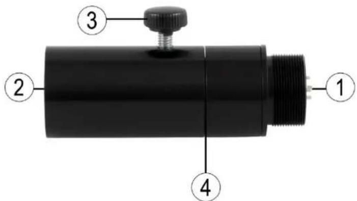
- Connection to the telescopic stick
- Connection to the operating element
- Rotary adjustment screw
- Allen screw
4.4 Digital monitor
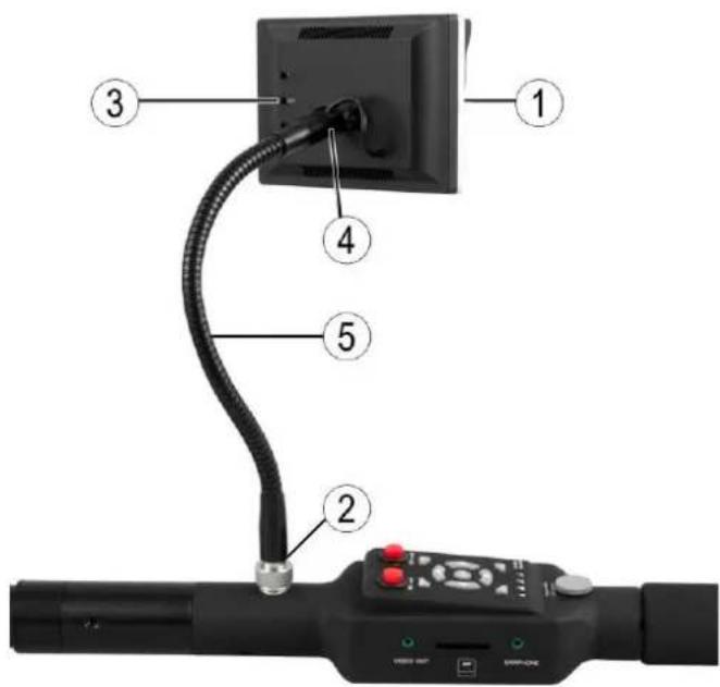
- TFT screen
- Monitor connection with knurled nut
- Buttons
- Inclinable monitor bracket
- Gooseneck
4.5 Operating Element
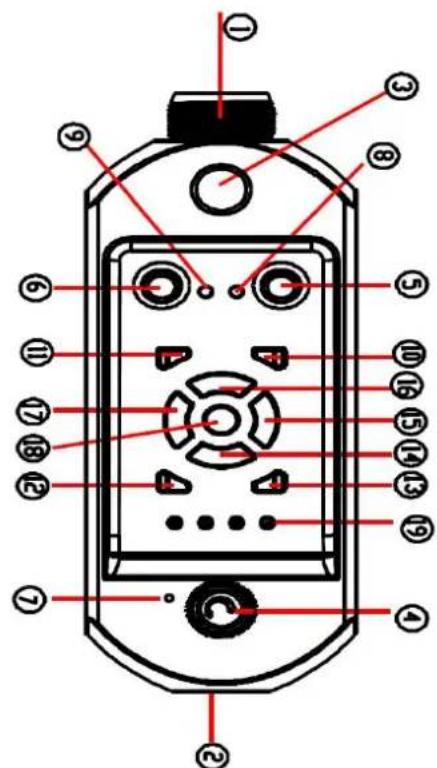

| No. | Button / designation | Function |
| 1 | Connector | Connection to the camera |
| 2 | Connector | Connection to the handle / battery |
| 3 | Plug | Connection to the monitor |
| 4 | Rotating knob | On / Off / dim LEDs |
| 5 | DVR button | Digital video recorder on / off |
| 6 | MIC button | Microphone on / off |
| 7 | Microphone | Microphone connection |
| 8 | DVR control light | Video recorder in operation |
| 9 | MIC control light | Microphone in operation |
| 10 | ESC button | Go back / play |
| 11 | MENU button | Main menu |
| 12 | P/P button | Photograph / Play / Pause / Delete a file |
| 13 | STOP button | Stop |
| 14 | ▲ button | Up / increase volume |
| 15 | ▼ button | Down / reduce volume |
| 16 | ◀ button | To the left / rewind |
| 17 | ▶ button | To the right / fast forward |
| 18 | OK button | Confirm entry |
| 19 | Battery indicator | Shows battery level |
| 20 | Video port | Connection to another monitor |
| 21 | SD card slot | Interface for the SD card |
| 22 | Headphone jack | Headphone connector |
4.6 Handle

natural_image
Black cylindrical object with two labeled points (1 and 2) pointing to its ends, no text or symbols present.- Connection
- 12 V charging connector
4.7 Guide roller with mounting fixture
The guide roller allows to move the device in areas which are hard to access and avoids damage like scratches.

natural_image
Close-up of a black mechanical device with two wheels and adjustment knobs (no visible text or symbols)4.8 Mounting
- Take off the protecting cases of the components.
- Attach the guide roller to the telescopic stick.

natural_image
Black cylindrical mechanical component with flanges and a circular base (no text or symbols visible)- Connect the camera head to the connecting piece of the telescopic stick.

natural_image
Black mechanical tool with cylindrical and threaded ends, no visible text or symbols- Connect the rotary coupling to the other connecting piece of the telescopic stick.

natural_image
Black mechanical tool with attached cylindrical and linear components (no visible text or symbols)- Connect the operating element to the connecting piece of the rotary coupling.

natural_image
Black cylindrical mechanical device with attached lever and adjustment knob (no visible text or symbols)- Connect the handle to the connecting piece of the operating element.

natural_image
Black and white photo of a handheld industrial tool with attached components (no visible text or symbols)- Connect the monitor to the operating element and tighten the nut firmly.

natural_image
Side view of a black handheld optical instrument with a curved lens and attached sensor (no text or symbols visible)5 Instructions
- Turn the knob clockwise to turn on the device, to activate the LEDs and to adjust the brightness.
- Align the screen.
- Extend the second and third telescopic shaft. Do not forget to screw the connecting parts firmly, otherwise the shaft retracts. Retract the shaft when taking close-ups.
- The flexible connection of the camera head can be bent to bring the camera into the correct position.
- Use the rotary coupling to adjust the direction of the camera.
- Note the battery level. The system turns off automatically when the battery level is too low.
- Use the 12 V charging connection to recharge. Do not use the battery during the charging process.
- If you do not need the video recorder, then switch it off to save battery power.
- Insert the SD card correctly.
- When you are in standby mode, press the P/P button to take a picture and the OK button to start recording.
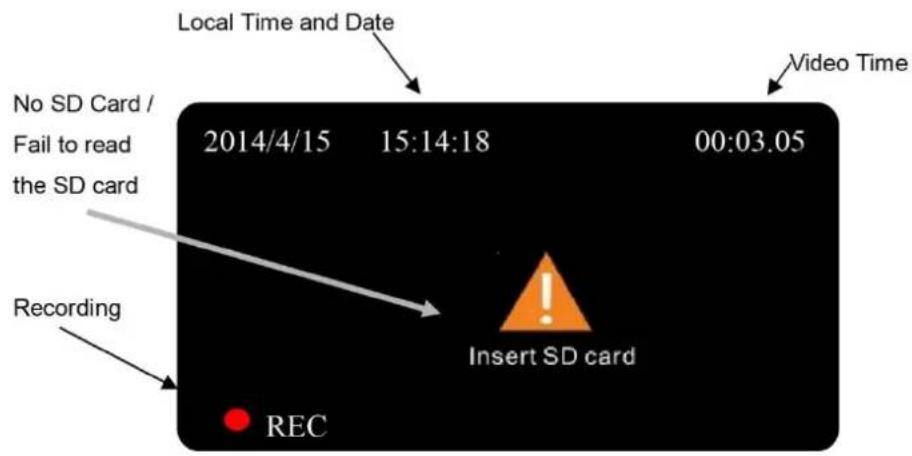
6 Screen symbols
6.1 Standby mode

6.2 Recording mode
7 DVR setting
7.1 Image setting
7.1.1 Image quality adjustment
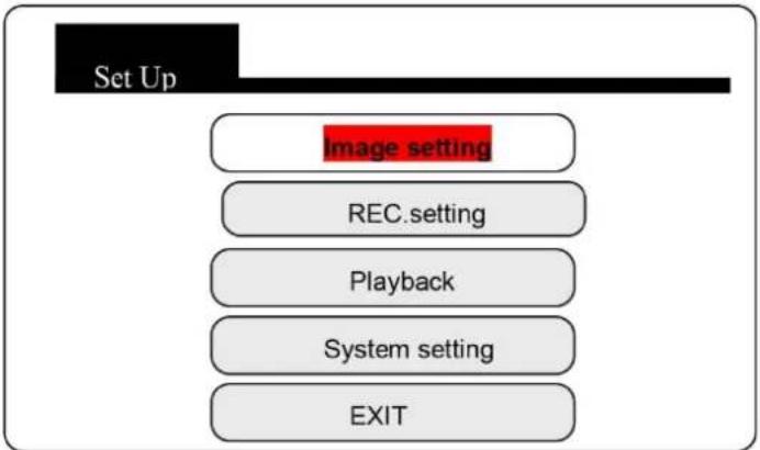
flowchart
graph TD
    A["Set Up"] --> B["Image setting"]
    B --> C["REC. setting"]
    C --> D["Playback"]
    D --> E["System setting"]
    E --> F["EXIT"]
Press the "Menu" button to enter the main menu.
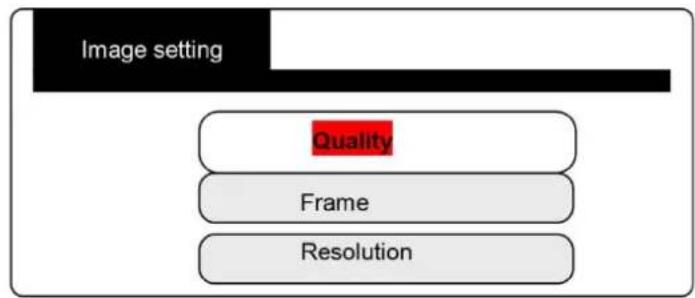
flowchart
graph TD
    A["Image setting"] --> B["Quality"]
    A --> C["Frame"]
    A --> D["Resolution"]

H = high quality
M= medium quality
L = low quality
7.1.2 Frame rate setting

flowchart
graph TD
    A["Image Setting"] --> B["Quality"]
    A --> C["Frame Rate"]
    A --> D["Resolution"]
    C --> E["30fps"]
    D --> F["15fps"]
    D --> G["5fps"]
30 fps: liquid image
15 fps: non-liquid image
5 fps: irregular image
7.1.3 Resolution setting
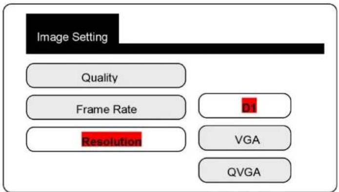
D1: 704 x 576
VGA: 640 x 576
QVGA: 320 x 288
7.2 REC setting
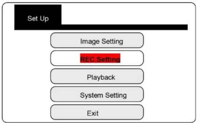
flowchart
graph TD
    A["Set Up"] --> B["Image Setting"]
    B --> C["REC.Setting"]
    C --> D["Playback"]
    D --> E["System Setting"]
    E --> F["Exit"]
Press the "Menu" button to enter the main menu.
7.2.1 Overwrite
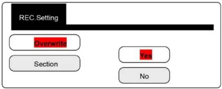
Note: if the SD card is full, the video recorder deletes the last 300 MB and then starts recording new files.
7.2.2 Rec. duration

flowchart
graph TD
    A["REC. Setting"] --> B["Overwrite"]
    B --> C["Section"]
    C --> D["1min"]
    C --> E["5min"]
    C --> F["15min"]
    C --> G["30min"]
    C --> H["1hr"]
7.3 Playback and deletion of a video file

flowchart
graph TD
    A["Set Up"] --> B["Image Setting"]
    A --> C["REC.Setting"]
    A --> D["Playback"]
    A --> E["System Setting"]
    A --> F["Exit"]
Press the "OK" button to open the list of video files.
| File Name | Date | Start Time | |
| ASF | 00000001 | 2014/4/14 | 05:06:50 |
| ASF | 00000002 | 2014/4/14 | 05:56:02 |
| ASF | 00000003 | 2014/4/14 | 00:32:55 |
| ASF | 00000004 | 2014/4/14 | 11:14:05 |
| Page 01 / 14 | |||
Deletion:
- Press ▲ / ▼ to select a file.
- Press the P/P button to delete a file.
Playback:
- Press ▲ / ▼ to select a file and then press the OK button.
- Press the P/P button to play the file.
Video fast forward / rewind: (2, 4, 6, 16 x playback to select)
When you play the video, press the ▶ key to fast forward and the ◀ key to rewind.
Set the volume:
When the video is playing, press the ▲ key to increase the volume or the ▼ key to decrease the volume.
The highest volume level is 8. The lowest volume level is 0.
Pause:
When the video is playing, press the P / P button to pause the video. Press again to play the video again.
Stop:
When the video is playing, press the STOP button to stop the playback.
Exit playback mode:
Press the ESC button to return to the list of video files.
7.4 System settings

flowchart
graph TD
    A["Set Up"] --> B["Image Setting"]
    A --> C["REC.Setting"]
    A --> D["Playback"]
    A --> E["System Setting"]
    A --> F["Exit"]
Press the OK button to enter the settings.
7.4.1 Language settings
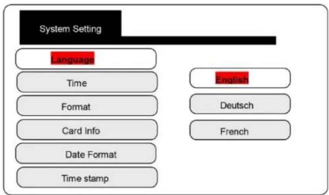
flowchart
graph TD
    A["System Setting"] --> B["Language"]
    B --> C["Time"]
    C --> D["Format"]
    D --> E["Card Info"]
    E --> F["Date Format"]
    F --> G["Time stamp"]
    H["English"] --> I["Deutsch"]
    H --> J["French"]
Select the appropriate language.
7.4.2 Time and date setting
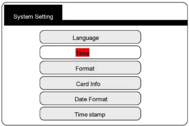
flowchart
graph TD
    A["System Setting"] --> B["Language"]
    B --> C["Time"]
    C --> D["Format"]
    D --> E["Card Info"]
    E --> F["Date Format"]
    F --> G["Time stamp"]
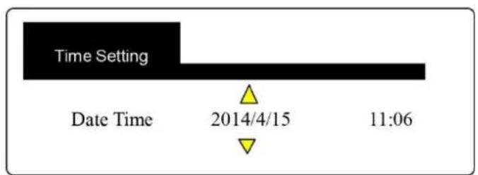
Press the ◀ / ▶ keys to move the cursor.
Press the ▲ / ▼ keys to set the time.
Press the OK button to save the setting.
7.4.3 Formatting

flowchart
graph TD
    A["System Setting"] --> B["Language"]
    A --> C["Time"]
    A --> D["Format"]
    A --> E["Card Info"]
    A --> F["Date Format"]
    A --> G["Time stamp"]
    D --> H["Yes"]
    D --> I["No"]
Select "Yes" to format the SD card.
Note: "Formatting" deletes all files from the SD card (the files cannot be restored).
7.4.4 SD card capacity check
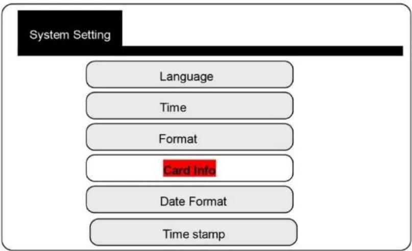
flowchart
graph TD
    A["System Setting"] --> B["Language"]
    A --> C["Time"]
    A --> D["Format"]
    A --> E["Card Info"]
    A --> F["Date Format"]
    A --> G["Time stamp"]
Card info
Total Size : 7598MB
Usage Size : 0.1%
Remain Size : 99.9%
7.4.5 Date format

flowchart
graph TD
    A["System Setting"] --> B["Language"]
    A --> C["Time"]
    A --> D["Format"]
    A --> E["Card Info"]
    A --> F["Date Format"]
    A --> G["Time stamp"]
    H["YYYYMMDD"] --> I["YYYYMMDD"]
    J["DDMMYYYY"] --> K["DDMMYYYY"]
    L["MMDDYYYY"] --> M["MMDDYYYY"]
7.4.6 Time display on the screen
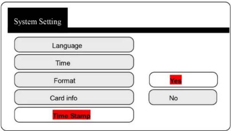
flowchart
graph TD
    A["System Setting"] --> B["Language"]
    A --> C["Time"]
    A --> D["Format"]
    A --> E["Card info"]
    A --> F["Time Stamp"]
    G["Yes"] --> H["No"]
8 FAQ
| All the parts have been fastened, but nothing is displayed after turning on the device. | Check carefully whether all the parts have been assembled correctly and whether the battery is sufficiently charged. |
| The menu does not open. | Check if the status light for the DVR is on. If not, turn on the DVR. |
| After recording, there is no file on the SD card. | 1. Check if the data can be written to the SD card. Insert the card correctly.2. Check whether the DVR can read the SD card or not. |
| The recording has no sound. | Check whether the MIC button has been pressed. Use the correct headphones. |
| The video file is damaged. | Do not remove the SD card while recording. |
9 Disposal
For the disposal of batteries in the EU, the 2006/66/EC directive of the European Parliament applies. Due to the contained pollutants, batteries must not be disposed of as household waste. They must be given to collection points designed for that purpose.
In order to comply with the EU directive 2012/19/EU we take our devices back. We either re-use them or give them to a recycling company which disposes of the devices in line with law.
For countries outside the EU, batteries and devices should be disposed of in accordance with your local waste regulations.
If you have any questions, please contact PCE Instruments.

10 Contact
If you have any questions about our range of products or measuring instruments, please, contact PCE Instruments.
10.1 PCE Instruments UK
By post:
PCE Instruments UK Ltd.
Units 12/13 Southpoint Business Park
Ensign Way, Southampton
Hampshire
United Kingdom, SO31 4RF
By phone:
02380 987 035
10.2 PCE Americas
By post:
PCE Americas Inc.
711 Commerce Way
Suite 8
Jupiter
33458 FL
USA
By phone:
561 320 9162


- Manual Industrial Endoscope PCE-IVE 320
- Contents
- Introduction
- Safety notes
- System Description
- Camera Head
- Telescopic stick
- Rotary Coupling
- Digital monitor
- Operating Element
- Handle
- Guide roller with mounting fixture
- Mounting
- Instructions
- Screen symbols
- Standby mode
- Recording mode
- DVR setting
- Image setting
- Image quality adjustment
- Frame rate setting
- Resolution setting
- REC setting
- Overwrite
- Rec. duration
- Playback and deletion of a video file
- Deletion:
- Playback:
- Set the volume:
- Pause:
- Stop:
- Exit playback mode:
- System settings
- Language settings
- Time and date setting
- Formatting
- SD card capacity check
- Date format
- Time display on the screen
- FAQ
- Disposal
- Contact
- PCE Instruments UK
- By post:
- By phone:
- PCE Americas
Brand : PCE
Model : IVE 320
Category : Measurement