
VE 1014N-F - Measurement PCE - Free user manual and instructions
Find the device manual for free VE 1014N-F PCE in PDF.


| Product Type | Digital Multimeter |
| Brand | PCE |
| Model | VE 1014N-F |
| Category | Measurement |
| Dimensions (approx.) | 180 x 85 x 45 mm |
| Weight (approx.) | 350 g (including battery) |
| Power Supply | 9V battery (6F22 type) |
| Display | LCD with backlight, 6000 counts |
| DC Voltage Range | 600 mV to 1000 V |
| AC Voltage Range | 600 mV to 750 V |
| DC Current Range | 600 µA to 10 A |
| Resistance Range | 600 Ω to 60 MΩ |
| Capacitance Measurement | Yes, up to 1000 µF |
| Frequency Measurement | Yes, up to 10 MHz |
| Diode Test | Yes |
| Continuity Test | Yes, with buzzer |
| Safety Rating | CAT III 600 V, CAT II 1000 V |
| Data Hold | Yes |
| Auto Power Off | Yes, adjustable |
| Maintenance | Clean with dry cloth; replace battery when low |
| Spare Parts / Repairability | Replaceable fuse, battery; professional repair recommended for internal issues |
| Included Accessories | Test leads, 9V battery, user manual |
Frequently Asked Questions - VE 1014N-F PCE
User questions about VE 1014N-F PCE
0 question about this device. Answer the ones you know or ask your own.
Ask a new question about this device
Download the instructions for your Measurement in PDF format for free! Find your manual VE 1014N-F - PCE and take your electronic device back in hand. On this page are published all the documents necessary for the use of your device. VE 1014N-F by PCE.
USER MANUAL VE 1014N-F PCE
natural_image
Black-and-white photo of a handheld electronic device displaying a digital screen with a textured circular pattern and control buttons (no readable text or symbols)User Manual
PCE-VE 1000 Videoscope

User manuals in various languages (Deutsch, français, italiano, español, português, nederlands, türk, polski, русский , 中文) can be downloaded here:
www.pce-instruments.com
Last change: 25 October 2017
v1.0
Contents
1 Safety notes....2
2 System description 3
3 Preparations 7
4 Make recordings....7
4.1 Record images....7
4.2 Record videos....7
5 SD card....7
6 Functions....7
6.1 Setting the brightness....7
6.2 Zoom....8
6.3 Rotating and reflecting the image 8
6.4 Pre-timed video recordings....8
6.5 Playback function....8
6.6 Functions for video recording 9
7 Settings....9
7.1 General settings....9
7.2 SD card....9
7.3 Language....10
7.4 Date and time....10
7.5 Automatic shutdown....10
8 Connectors 10
9 Maintenance 11
9.1 Replacing the borescope cable ....11
9.2 Firmware update ....11
10 Borescope cables 12
10.1 Borescope cable with a swivelling camera....12
10.2 HR borescope cable....14
11 Contact....21
12 Disposal 21
1 Safety notes
Please read this manual carefully and completely before you use the device for the first time. The device may only be used by qualified personnel and repaired by PCE Instruments personnel. Damage or injuries caused by non-observance of the manual are excluded from our liability and not covered by our warranty.
- The device must only be used as described in this instruction manual. If used otherwise, this can cause dangerous situations for the user and damage to the meter.
- The instrument may only be used if the environmental conditions (temperature, relative humidity, ...) are within the ranges stated in the technical specifications. Do not expose the device to extreme temperatures, direct sunlight, extreme humidity or moisture.
- Do not expose the device to shocks or strong vibrations.
- The case should only be opened by qualified PCE Instruments personnel.
- Never use the instrument when your hands are wet.
- You must not make any technical changes to the device.
- The appliance should only be cleaned with a damp cloth. Use only pH-neutral cleaner, no abrasives or solvents.
- The device must only be used with accessories from PCE Instruments or equivalent.
- Before each use, inspect the case for visible damage. If any damage is visible, do not use the device.
- Do not use the instrument in explosive atmospheres.
- The measurement range as stated in the specifications must not be exceeded under any circumstances.
- Non-observance of the safety notes can cause damage to the device and injuries to the user.
We do not assume liability for printing errors or any other mistakes in this manual.
We expressly point to our general guarantee terms which can be found in our general terms of business.
If you have any questions please contact PCE Instruments. The contact details can be found at the end of this manual.
2 System description
2.1 Main unit

1 Record
2 Snap
3 Right / brighten
4 Up / zoom in
5 Left / dim
6 OK / Menu
7 Down / zoom out
8 Power / ESC
9 Rotate / mirror
10 Power indicator
11 Integrated microphone

1 Sun visor
2 Stand
2.2 Connectors
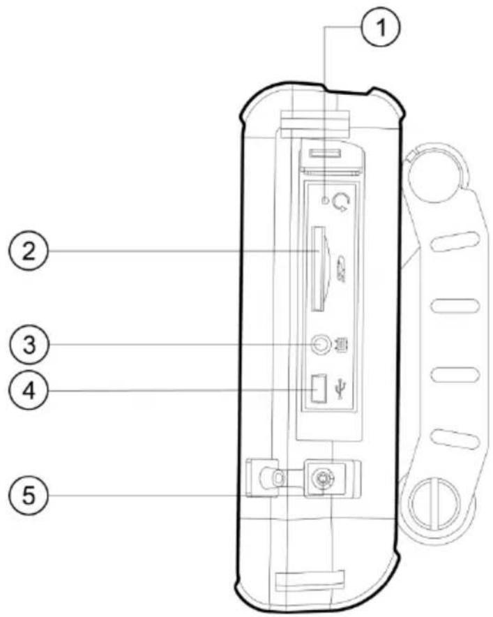
1 Reset
2 SD card slot
3 AV out
4 USB interface
5 DC in
2.3 Back
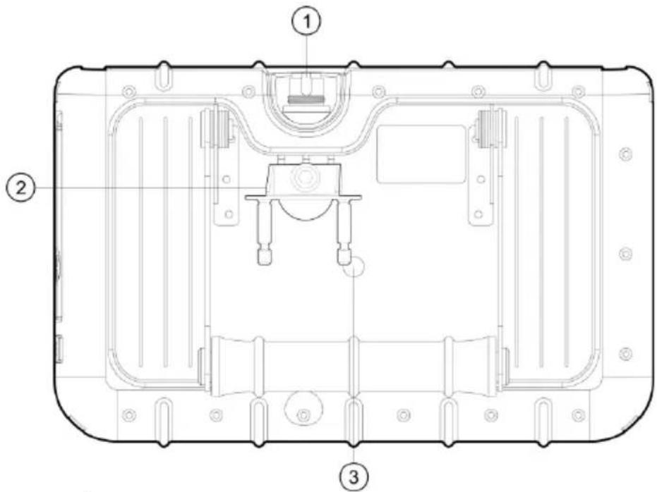
1 Insert tube connector
2 PRM280 mount
3 Tripod thread
2.4 Display

1 Date
2 Time
3 Repeat recording indicator
4 Brightness indicator
5 SD card status
6 Battery indicator
2.5 Display with included accessories

3 Preparations
- Before the first operation of the borescope the battery has to be charged completely. This can be done by connecting the device to the power.
- Take a borescope cable if available.
- Connect the borescope cable to the main unit. Make sure that the cable is inserted correctly and tighten the sealing nut.
- Switch on the device by pressing and holding the power button for about three seconds.
- Insert the SD card. Open the corresponding lid on the side and insert the card.
4 Make recordings
4.1 Record images
- Move the camera head to the desired area of inspection.
- Press the Snap button in order to save the displayed image.
4.2 Record videos
To save a video to the SD card, the camera head has to be moved to the inspection area as described above. After this, press the Record button to start recording. If the Record button is pressed once again, the recording will end and the video is automatically stored to the SD card. The name of the file will be displayed in the left information field underneath the time indication after the recoding has been stopped. Simultaneously with the video recording, an audio file will be recorded which allows the user to leave comments. Please note that it is not possible to zoom, rotate or reflect the image during video recordings.
5 SD card
The borescope uses SD cards to store images. It is possible to use SD cards with different capacities. Here you can store both images and videos. The amount of images and duration of the videos that can be stored vary with the different sizes of the SD cards. The approximate values can be seen in the chart below:
| SD card capacity | 4 GB | 8 GB | 16 GB | 32 GB |
| Amount of images | <31000 | <62000 | <124000 | <240500 |
| Duration of videos | <130 min | <160 min | <530 min | <1000 min |
6 Functions
6.1 Setting the brightness
To adjust the brightness of the live images you can use the corresponding buttons. The left function key is used to dim the light. The right one is used to brighten up the light. Ten brightness levels are available where five of them are normal brightness levels and the other ones are with higher exposure time. These are advantageous when the camera head is moved in dark environments.
6.2 Zoom
During the inspection of live images, digital zoom can be used. This can be done by pressing the Zoom-In and Zoom-Out buttons. If the “+”-button is pressed the image is enlarged. Pressing the “-”-button will zoom out again. The zoom ratio is scaled linearly starting from 1.0 x up to 5.0 x. Due to the fact that it is a digital zoom, it may occur that the quality of the image suffers when zooming in.
6.3 Rotating and reflecting the image
From time to time it is useful and or even necessary to rotate the image on the display without moving the camera head. This can have multiple reasons.
- Rotate image:
To rotate the image in steps of 90 ° the button must be pressed.
- Reflect image: The image is reflected if the button is pressed for more than three seconds. On the left-hand side of the display, will be shown. If the non-reflected image is displayed, the same procedure must be repeated.
6.4 Pre-timed video recordings
The borescope offers the opportunity to record pre-timed sequences which will be repeated after the time has run off. These sequences are recorded until the button is pressed again. The duration of the video can be 5, 10, 20 and 30 minutes. If the function is not activated, the recording will automatically be stopped after 30 minutes. To enable the single sequences, enter the main menu by pressing the button. After this, the and buttons must be used to get to the submenu "REPEAT RECORDING". Confirm by pressing once again. Now choose your desired duration by using the + and - buttons and confirm your choice by pressing OK. You can choose between 5, 10, 20, 30 minutes and "OFF".
6.5 Playback function
To review the last recorded files on the LCD, the E button must be pressed after the recording. The images will automatically be displayed after that. If a video has just been recorded, the O button must be pressed additionally to play the video.
You can scroll through the files:

switch to the previous file

switch to the next file

go 10 files back

go 10 files forward
When reviewing images you can also zoom to a desired area within the picture. You have the opportunity to zoom in in three steps. To do so, the image must be on the display. Then press OK. After this, a small window will appear in the bottom right corner of the LCD with a green frame, which shows the area which is enlarged. Pressing OK again enlarges the section once again. If the maximum enlargement of the section is reached and OK pressed once again, the device will switch to playback mode again. The specific section which is framed green can also be moved within the image:

left

right

up

down
A video file can be played (without the audio file) by pressing OK the video is selected.
In the playback function, unwanted files can also be deleted. In order to do so, the files have to be selected first. When reviewing them on the LCD, press The dialogue "DELETE FILE?"
will be shown with the answers "YES" and "NO". By using hand, you can make your choice (highlighted in green) which can be confirmed by pressing OK
To show thumbnails of saved images, press the 📄 button. The function keys help you to navigate through the thumbnails. On each page, nine files will be shown in a 3x3 grid. This makes it possible to delete more than one file at a time. This can be done by following these steps:
- Move the orange frame to the unwanted file. Use the arrow keys in the corresponding direction.
- Press to mark the chosen file. It will then be marked with an orange "X".
- When all unwanted files are marked, press the button to start the deletion process. The display will show "DELETE FILE?" and give you the options "YES" and "NO". Use and to make your choice and confirm by pressing . The data will then be deleted.
6.6 Functions for video recording
- Pause:
- Change the speed of the playback: or
- Fast forward / rewind or
OK


7 Settings
7.1 General settings
- Open main menu: When reviewing files, pressing opens the main menu
- Navigating through the main menu: and
- Open a submenu: OK
- Return to the higher menu level: ESC
7.2 SD card
- Check the state of the SD card: Open the main menu and then open the submenu "SD CARD STATUS".
- Format SD card: Open the main menu and open the submenu "SD CARD STATUS".
Choose "FORMAT SD CARD". Use and to choose "YES" and confirm your choice.
- Delete all files on the SD card: Open the main menu and then open the submenu "SD CARD STATUS". Choose "DELETE ALL FILES", go to "YES" and confirm your choice.
7.3 Language
Open the main menu and navigate to the submenu "LANGUAGE". Use and to navigate, choose your language and confirm your choice.
7.4 Date and time
System time
Open the main menu and navigate to the submenu "DATE / TIME". Use the + and - buttons to switch between the setting fields and + and - to set the values correctly. Confirm your choice by pressing OK
Time format
To set the correct time format enter the main menu first and then enter the submenu "DATE / TIME". You can go to the time format setting by using ⏻ and ⚠. Ⓧ and ◑ help you to choose the correct time format (YY/MM/DD, MM/DD/, DD/MM/YY). Confirm by pressing OK
Time and date stamp
The borescope gives you the opportunity to mark your files with a time and date stamp. To activate this function, enter the main menu and then enter the submenu "DATE / TIME". By using and you can get to the function "TIMESTAMP". Choose "YES" or "NO" and confirm with OK
7.5 Automatic shutdown
In order to reduce the battery consumption, the borescope has an automatic shutdown function that can be activated. To do so, enter the main menu and the submenu "AUTO POWER OFF". The buttons and can be used to navigate through the different time settings. You can choose between 5, 10, 20 and 30 minutes or deactivate this function by selecting "OFF". Confirm your choice by pressing off the device has turned itself off, it does not enter a sleep mode but switches off completely and must be restarted completely.
8 Connectors
8.1 USB
The USB interface is commonly used to connect the borescope to a computer. It supports two different modes. On the one hand it supports the data transmission and on the other hand it can help to display the live pictures on a computer. When the borescope is connected to a computer, it displays "READER" and "CAMERA". Depending on what mode needs to be set you can use the and buttons to make your choice. Confirm with . OK
You can also get there by entering the main menu and choosing the submenu "USB". If the device is connected via USB, a USB icon will appear in the left information box. If the reader function is chosen there will be a stylized SD card symbol on the display. The reader mode can be stopped by pressing ESC
8.2 AV output
The AV output serves to transfer files to a television in standard definition. HD is not supported.
- Connect the device to a TV using the AV cable.
- Use ⏻ and ⏱ to switch between "NTSC" and "PAL" (depending on the TV).
- Confirm with .OK
- You can leave the mode by pressing .ESC
9 Maintenance
9.1 Replacing the borescope cable
If a different cable needs to be installed to the borescope you can proceed as follows:
- Switch off the device.
- Loosen the cable from the device and pull it out carefully.
- Insert the different borescope cable. Note that the pins have to be inserted correctly.
- Tighten the sealing nut.
9.2 Firmware update
- Switch off the device. Press and hold ESC and simultaneously to enter factory mode.
- After this, the firmware version will be displayed.
- Copy the file of the new firmware to an SD card.
- Insert that SD card into your borescope.
- Press and to test on the device.
- The update will be made automatically.
- The instrument will switch off after the update.
10 Borescope cables
You have the opportunity to connect different cables to the borescope.
| PCE-VE 1yyz-ab | yy | z | a | b | Note |
| Cable length | |||||
| 1 m | 01 | ||||
| 2 m | 02 | Only 5.5 mm cable / head selectable | |||
| 3 m | 03 | Only 6 mm cable / head selectable | |||
| 10 m | 10 | Only 5.5 mm cable / head selectable | |||
| 22 m | 22 | Only 28 mm cable / head selectable (code 0) | |||
| ∅ cable head | |||||
| 3.9 mm | 3 | 2 cables included: 0 ° and 90 ° | |||
| 4.9 mm | 4 | With front and lateral camera | |||
| 5.5 mm | 5 | With front camera | |||
| 6 mm | 6 | 2-way | |||
| 28 mm | 0 | Always with 22 m cable | |||
| Resolution | |||||
| 320 x 240 | |||||
| 640 x 480 | HR | ||||
| Type of cable | n. a. for 22 m cable | ||||
| Flexible | -F | Only added for flexible cables | |||
| Semi-flexible (gooseneck) |
Special editions:
PCE-VE 1014N-F: 1.5 m cable length, 4.5 mm ∅ cable head, 2-way, large display
PCE-VE 1034N-F: 3 m cable length, 4.5 mm ∅ cable head, 2-way, large display
10.1 Borescope cable with a swivelling camera
- Camera tube
- Lens
- Bending neck
- Operating element
- Rotary knob
- Connection cable
- Connector plug
- Locking lever

Preparations
-
Insert the end of the borescope cable into the connection socket. Use the white dot on the borescope cable for your orientation, to know which way round it has to be inserted into the socket and tighten the sealing nut.
-
Turn on the borescope and place the camera head in the desired inspection area.
Operation
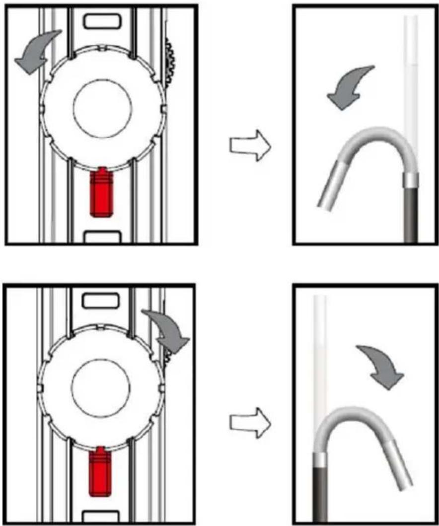
- Using the rotary knob, you can control the wire-draw mechanism. This moves the camera head. By turning the rotary knob clockwise the camera head will be bent to the right side. Turning the rotary knob counter-clockwise will turn the camera head to the left side.
ATTENTION: Overwinding the rotary knob will damage the wire-draw mechanism of the borescope cable.
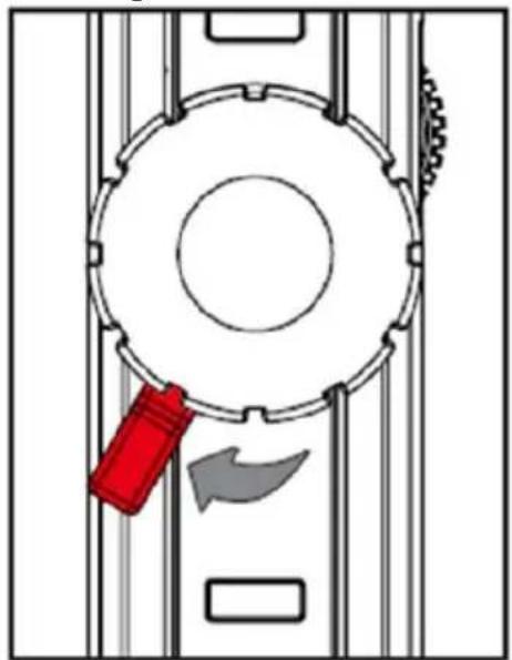
- The locking lever can be turned to the left side. By doing so, the camera head will remain in the position that has been selected before. It can be loosened by turning the locking lever to the neutral position in the middle. The camera head can then be moved again.
natural_image
Diagram of a mechanical device with a red tool and arrow indicating motion (no text or symbols)
natural_image
3D rendering of a curved metallic pipe or tube with a black end cap, isolated on white background (no text or symbols)10.2 HR borescope cable
In addition to the general safety notes of the device, please mind the following safety notes to prevent damage and injuries when using the HR camera cable.
- To avoid dangerous situations, make sure that the probe does not get in touch with inflammable liquids or gases.
- The HR cable includes various small cables which control the optics and electronics of the camera tip. To ensure high reliability, do not bend the cable to an angle of more than 90° and store the cable as little bent as possible.
- Do not disassemble the device as this can cause damage and electric shocks.
- Do not expose the device to direct sunlight and store it in a cool, dry, sufficiently ventilated place.
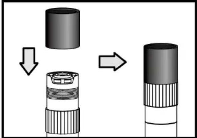
- To protect the camera module, make sure the protection ring is on the camera head as long as no accessories are in use.
- Do not apply force to the end of the cable and do not bend it. This can deteriorate your vision and even damage the probe.
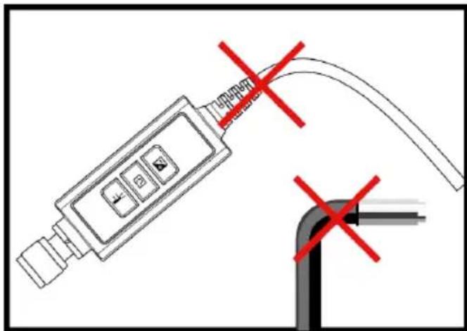
- When you roll up the cable, the inner diameter must be at least 15 cm.
- Put the protection ring back on and tighten it when not using the device for a longer period of time.
- Do not crash the probe head.
- Make sure that the camera does not get in contact with the following liquids: lead-free petrol, diesel oil, machine oil, brake fluid and transmission oil.

natural_image
Diagram showing a cylindrical component being folded into a layered cylindrical structure, with arrows indicating the process (no text or symbols present)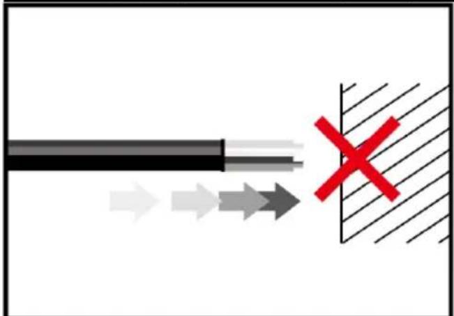
natural_image
Diagram showing a black cable with arrows pointing toward a cross-shaped object, no text or symbols present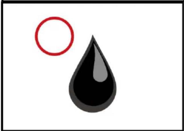
natural_image
Simple illustration of a red circle and a black droplet with a white outline (no text or symbols)- Do not screw the accessories on too tightly. Only screw it slightly until it is fixed.

natural_image
Mechanical component diagram showing a shaft and lever assembly (no text or symbols)- To clean the camera head, use the cleaning liquid and the swabs provided in the cleaning kit.

natural_image
Technical line drawing of a mechanical component with a pin and cylindrical body (no text or symbols)Technical specifications
| Length of camera head | 20 mm |
| Diameter with protection ring | 6 mm |
| Depth of field | 10 ... 60 mm |
| Field of view | 60.7° |
| Protection class | IP67 |
System description


- Probe: to guide the camera
- Camera head: for illumination and capturing
- Assembly ring: to attach accessories
- Protection ring: to protect the thread
- Red cap: protects the camera when not in use
- Boost key: for better illumination in dark environments
- Rotation key: Press once to turn the display counter-clockwise by 90°. The red LED will light up. The LED will stop glowing when the original position has been reached.
- Light key: This key activates a mirror which enables particle-free vision.
-
Connector
-
Probe: to guide the camera
- Bending neck
- Camera head: for illumination and capturing
- Assembly ring: to attach accessories
- Protection ring: to protect the thread
- Red cap: protects the camera when not in use
- Rotary knob
- Locking lever
- Boost key: for better illumination in dark environments
- Rotation key: Press once to turn the display counter-clockwise by 90°. The red LED will light up. The LED will stop glowing when the original position has been reached.
- Light key: This key activates a mirror which enables particle-free vision.
12.Lock: To lock button functions - Connecting Cable
- Connector
Getting started
Connection
Step 1: Connect the main unit with the connector and fix it with the screw mechanism.
Step 2: Switch on the system. You should now see a picture in the display.
Attachment of the accessories
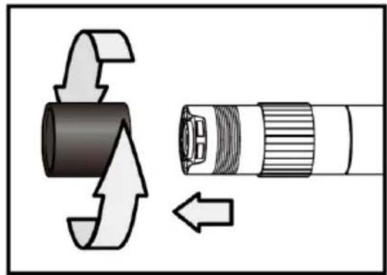
Mirror
Step 1: Unscrew the thread protection ring.
Step 2: Screw the assembly ring down to the bottom.
Step 3: Screw the mirror attachment onto the thread until the thread is completely covered.
natural_image
Diagram showing a mechanical component with directional arrows indicating motion or force (no text or symbols)
natural_image
Diagram showing a mechanical component being inserted into a cable, with arrows indicating direction (no text or symbols present)Step 4: Align the lateral LED opening of the mirror attachment in a way that the LEDs are uncovered.
Step 5: Turn the assembly ring upwards in order to fix the mirror attachment.

natural_image
Diagram of a mechanical device with directional arrows indicating motion or force (no text or symbols)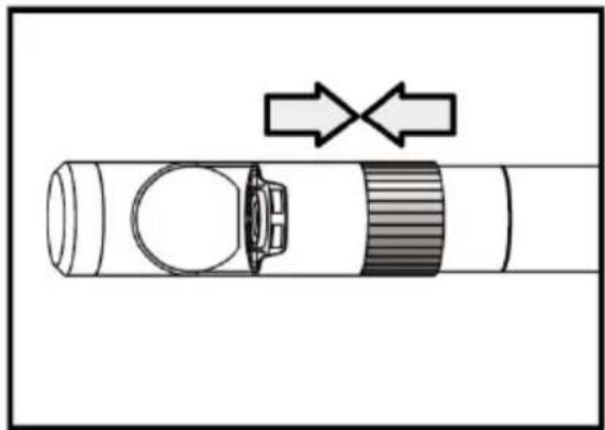
natural_image
Diagram of a mechanical component with directional arrows indicating movement or force (no text or symbols)Step 6: Press the light key to activate the lateral light.
Step 7: Adjust the light intensity as required to ensure ideal vision to the side.

natural_image
Illustration of a flashlight with a red X mark and a black tip, no text or symbols present
natural_image
Diagram of a cylindrical device with a red cap and a black handle, showing internal components and a red circle on the top (no text or symbols)(Steps 4-5 must be repeated until the right position is reached)
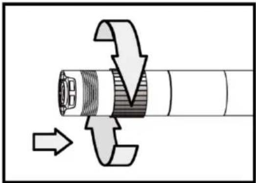
Magnetic hook
Step 1: Turn the assembly ring down to the bottom.
Step 2: Screw the magnetic hook on until it snaps in.
natural_image
Mechanical assembly diagram showing a shaft and threaded component with directional arrows indicating motion (no text or symbols)
natural_image
Mechanical component diagram showing a shaft being cut with directional arrows indicating motion (no text or symbols)Climbing ball
Step 1: Remove the assembly ring.
Step 2: Screw the climbing ball on until it snaps in.

natural_image
Mechanical assembly diagram showing a cylindrical component being inserted into a threaded shaft with directional arrows indicating motion (no text or symbols)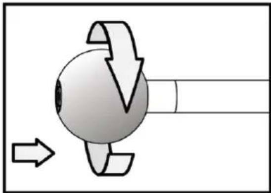
natural_image
Diagram of a rotating mechanical component with directional arrows indicating motion (no text or symbols)Please note that the magnetic hook and the climbing ball can only be attached to borescope cables with a diameter of 5.5 mm.
Operation
Boost key

Use this key in a dark environment. The red LED indicates that the Boost function has been activated. The image will be lightened up.
Note: Hold the probe steady.

natural_image
Close-up of a curved metallic object against a dark textured background (no visible text or symbols)Before "boosting"

natural_image
Close-up of a curved metallic pipe or pipe with textured surface (no visible text or symbols)After "boosting"
Rotation key

You can use this key to turn the image by 90irc four times, for instance, when trying to read an inscription completely.

Light key

When using the mirror attachment, this key improves the vision which will not be impeded by particles, dust, etc.

natural_image
Blurred close-up of a dark, reflective surface with scattered light spots (no text or symbols visible)Without "particle free" function

natural_image
Close-up of a dark, circular object with small white specks, possibly a mechanical part or surface (no visible text or symbols)With "particle free" function
11 Contact
If you have any questions, suggestions or technical problems, please do not hesitate to contact us. You will find the relevant contact information at the end of this user manual.
12 Disposal
For the disposal of batteries in the EU, the 2006/66/EC directive of the European Parliament applies. Due to the contained pollutants, batteries must not be disposed of as household waste. They must be given to collection points designed for that purpose.
In order to comply with the EU directive 2012/19/EU we take our devices back. We either re-use them or give them to a recycling company which disposes of the devices in line with law.
For countries outside the EU, batteries and devices should be disposed of in accordance with your local waste regulations.
If you have any questions, please contact PCE Instruments.



PCE Instruments contact information
Germany France Spain
PCE Deutschland GmbH PCE Instruments France EURL PCE Ibérica S.L.
Im Langel 4 76, Rue de la Plaine des Bouchers Calle Mayor, 53
D-59872 Meschede 67100 Strasbourg 02500 Tobarra (Albacete)
United States of America
PCE Americas Inc.
711 Commerce Way suite 8
Jupiter / Palm Beach
33458 FL
USA
Tel: +1 (561) 320-9162
Fax: +1 (561) 320-9176
info@pce-americas.com
www.pce-instruments.com/us
United Kingdom Italy
PCE Instruments UK Ltd
Units 12/13 Southpoint Business Park
Ensign Way, Southampton
Hampshire
United Kingdom, SO31 4RF
Tel: +44 (0) 2380 98703 0
Fax: +44 (0) 2380 98703 9
info@industrial-needs.com
www.pce-instruments.com/english
PCE Italia s.r.l.
Via Pesciatina 878 / B-Interno 6
55010 LOC. GRAGNANO
CAPANNORI (LUCCA)
Italia
www.pce-instruments.com/dutch www.pce-instruments.com/chile
Chile Hong Kong
PCE Instruments Chile SPA
RUT 76.423.459-6
PCE (Beijing) Technology Co., Ltd
1519 Room, 6 Building
Men Tou Gou Xin Cheng,
Men Tou Gou District
102300 Beijing
China Tel: 0212 471 11 47
Tel: +86 (10) 8893 9660
info@pce-instruments.cn info@pce-cihazlari.com.tr
www.pce-instruments.cn
Turkey
Pehlivan Sok. No.6/C
www.pce-instruments.com/turkish


- User Manual
- Contents
- Safety notes
- System description
- Display with included accessories
- Preparations
- Make recordings
- Record images
- Record videos
- SD card
- Functions
- Setting the brightness
- Zoom
- Rotating and reflecting the image
- Pre-timed video recordings
- Playback function
- Functions for video recording
- Settings
- General settings
- SD card
- Language
- Date and time
- System time
- Time format
- Time and date stamp
- Automatic shutdown
- Connectors
- USB
- AV output
- Maintenance
- Replacing the borescope cable
- Firmware update
- Borescope cables
- Special editions:
- Borescope cable with a swivelling camera
- Preparations
- Operation
- HR borescope cable
- Getting started
- Connection
- Attachment of the accessories
- Mirror
- Magnetic hook
- Climbing ball
- Boost key
- Rotation key
- Light key
- Contact
- Disposal
- PCE Instruments contact information
- Germany France Spain
- United States of America
- United Kingdom Italy
- Chile Hong Kong
- Turkey
Brand : PCE
Model : VE 1014N-F
Category : Measurement