PA6000 - Measurement PCE - Free user manual and instructions
Find the device manual for free PA6000 PCE in PDF.

| Brand | PCE |
| Model | PA6000 |
| Product Type | Digital Multimeter |
| Measurement Functions | AC/DC Voltage, AC/DC Current, Resistance, Capacitance, Frequency, Diode Test, Continuity Test |
| Display | 6000-count LCD with backlight |
| Auto-ranging | Yes |
| Data Hold | Yes |
| Max/Min Recording | Yes |
| Relative Measurement | Yes |
| Safety Rating | CAT III 600V, CAT II 1000V |
| Power Supply | 2 x 1.5V AAA batteries |
| Dimensions | 180 x 80 x 50 mm |
| Weight | 350 g (with batteries) |
| Operating Temperature | 0°C to 40°C |
| Storage Temperature | -10°C to 50°C |
| Accessories Included | Test leads, thermocouple, carrying case, batteries, manual |
| Maintenance | Clean with dry cloth; do not use solvents |
| Reparability | No user-serviceable parts; contact authorized service center |
Frequently Asked Questions - PA6000 PCE
User questions about PA6000 PCE
0 question about this device. Answer the ones you know or ask your own.
Ask a new question about this device
Download the instructions for your Measurement in PDF format for free! Find your manual PA6000 - PCE and take your electronic device back in hand. On this page are published all the documents necessary for the use of your device. PA6000 by PCE.
USER MANUAL PA6000 PCE
Southpoint Business Park
Ensign way
Hampshire / Southampton
United Kingdom, SO31 4RF
From outside UK: +44
Tel: (0) 2380 98703 0
Fax: (0) 2380 98703 9
info@pce-instruments.co.uk
www.pce-instruments.com/english
www.pce-instruments.com
POWER ANALYZER USA From outside US: +1 Tel: (561) 320-9162 Fax: (561) 320-9176 info@pce-americas.c www
PCE-PA6000
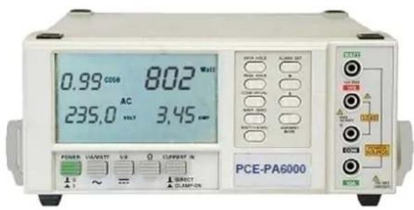
Your purchase of this POWER ANALYZER marks a step forward for you into the field of precision measurement. Although this POWER ANALYZER is a complex and delicate instrument, its durable structure developed. Please read the following instructions carefully and always keep this manual within easy reach.
OPERATION MANUAL
Caution Symbol
Caution :
* Risk of electric shock!
* During the measurement, do not open the cabinet.

Caution :
* Do not apply the overload voltage, current to the input terminal!
* Remove test leads before open the battery cover!
* Cleaning - Only use the dry cloth to clean the plastic case!
Environment Conditions
* Installation categories II .
* Pollution Degree 2.
* Altitude up to 2000 meters.
* Indoor use.
* Relative humidity 80% max.
TABLE OF CONTENTS
- FEATURES.... 1
- SPECIFICATIONS.... 1
2-1 General Specifications.... 1
2-2 Electrical Specifications.... 3
- FRONT PANEL DESCRIPTION....8
- PRECAUTIONS & PREPARATIONS FOR MEASUREMENT....10
- MEASURING PROCEDURE ...... 10
5-1 AC Watt/V/A/PF, Hz Measurement .....11
5-2 AC VA/V/A/PF, Hz Measurement .....12
5-3 AC Watt Hour ( Whr ) Measurement 13
5-4 AC Voltage, Current Measurement .....13
5-5 DC Volta ge, Current Measurement .....14
5-6 Ohm Measurement....15
5-7 AC Watt, VA, Whr measurement, current input cooperate with CT (current transformer)......15
5-8 AC Watt, VA, Whr measurement, current input cooperate with Clamp-On Probe....16
5-9 Data Hold.... 17
5-10 Peak Hold....17
5-11 Alarm Setting....18
- MAINTENANCE....18
6-1 Battery Replacement 19
6-2 Cleaning....19
- RS232 PC SERIAL INTERFACE.... 20
1. FEATURES
* Multi-functions : WATT, VA, Whr, COS θ (Power factor), ACV, ACA, DCV, DCA, Hz, ohm.
* True AC power( Watt ) & apparent power ( VA ) measurement.
* True rms display for ACV, ACA.
* 0.1 W resolution (< 1000 W), high precision an high resolution in the low wat range, good performance for low power LED lamp watt measurement.
* Large LCD, easy to read-out, display the Watt, Power factor, Voltage & Current value at the same time.
* Accept different kinds current input signal as direct input, inductive clamp probe or CT (current transformer).
* Auto range.
* Built-in peak hold & data hold function.
* Watt & VA measurement with Hi, low alarm setting capability.
* RS-232 output interface.
* Exclusive custom exclusive design LSI circuit, provides high accuracy, reliability and durability.
* Built-in over input indication.
* Power supply by batteries or AC to DC adapter.
* Built-in low battery indicator.
* Durable bench type housing plastic case with carrying handle.
2. SPECIFICATIONS
2-1 General Specifications
| Display * 93 mm x | 52 mm large LCD ( Liquid Crystal Display) display.* Multi-display unit, show Volt, Ampere, Watt, Power factor or Hz at same time. |
| Measurement WATT, VA, Whr,, Power factor, ACV, ACA, DCV, DCA, Hz, ohm. | |
| Zero Adjustment | Whr:External adjustment by push button. |
| DCV, ACV, DCA, ACA :Automatic adjustment. | |
| Polarity Automatic | switching, "-" indicates reverse polarity. |
| Current input Direct mode | input, inductive clamp probe or CT. |
| Over input Indication of " - - - - " or " - - - - ".Indication | |
| Data Output RS232 | serial interface. |
| Sampling Time | W, VA, ACA, ACV, COS θ , Hz :Approx. 1.5 Sec. |
| DCV, DCA, OHM :Approx. 1 Sec. | |
| Operating Temp. 0 | to 50 (32 to 122).°C °F |
| Operating Less than Humidity | 80 % R.H.. |
| Power Supply | Battery power :DC 9V, 1.5 V AA (UM-3) battery x 6 PCs. |
| AC power :AC to DC 9V adapter (500 mA), optional. | |
| Power Consumption Approx. DC 55 mA | Battery power : |
| Dimension 280 x 210 x 90 mm (11.0 x 8.3 x 3.5 inch). | |
| Weight Approx. 1.6 Kg (3.52 LB). | |
| Standard Accessories Instruction Manual...... 1 PC. | Test leads (red & black)......1 pair. |
2-2 Electrical Specifications (23±5) ℃
| Watt (AC, true power),current mode from direct input | ||
| Range Resolution Accuracy | ||
| 6,000 Watt 0.1 Watt (< 1000W) ± (1.5% + 5d) | ||
| * Accuracy is specified under the following conditions:a) AC input current is 0.05 ACA & ≥ 10 ACA. ≤b) AC input voltage is within 110 V± 15 % and 220V± 15%.c) ACA, ACV input signal is sine wave, 50/60 Hz.d) Power factor ≥0.5.* ACA, ACV frequency response is from 40 to 400 Hz.* Max. volt & current input signal value :Volt input : Max. AC 600V, Current input : Max. AC 10A | ||
| Watt (AC, true power),current input cooperate with inductive probe or CT | ||
| Range Resolution | ||
| 0.1 to 999.9 Watt 0.1 Watt | ||
| 9,999 Watt 1 Watt | ||
| 99.99 KW 0.01 KW | ||
| 999.9 KW 0.1 kW | ||
| * Accuracy will be same as the above " Direct Current Input Mode " but plus the accuracy value of Current Transformer ( CT ) or the accuracy value of Inductive Current Probe.* Input current should obey :Inductive Probe : ≥20 ACA.CT 100/5 A : ≥ 8 ACA.CT 1000/5 A : ≥ 80 ACA. | ||
| VA ( AC, Apparent Power )current mode from direct input | ||
| Range Resolution Accuracy | ||
| 99.99 VA 0.01 VA ± ( 2 % + 2d ) | ||
| 999.9 VA 0.1 VA | ||
| 9,999 VA 1 VA | ||
| * Accuracy is specified under the following conditions :a) AC input current is 0.05 ACA & ≥ ≤ 10 ACA.b) AC input voltage is within 110 V± 15 % and 220V 15%.c) ACA, ACV input signal is sine wave, 50/60 Hz. | ||
* ACA, ACV frequency response is from 40 to 400 Hz.
| POWER FACTORcurrent mode from direct input only | ||
| Range Resolution Accuracy | ||
| 0.01 to 1.00 0.01 ± (1.5% + 2 d) | ||
| * Accuracy are specified under the following conditions:a) AC input current is 0.05 ACA & 10 ACA.≥b) AC input voltage is within 110 V 15 % and 220V 15%.c) ACA, ACV input signal is sine wave, 50/60 Hz.* Max. volt & current input value :Volt input : AC 600V, Current input : AC 10A | ||
| AC VOLTAGE ( true rms ), DC VOLTAGE | ||
| Range | Resolution | Accuracy |
| 0.1 V to 299.9 V 0.1 V | DCV:±(1%+1d)ACV (10 V):≤±(1%+7d)ACV (11 V to 100 V):±(1%+5d)ACV (Others):±(1%+1d) | |
| 300 V to 600 V 1 V | ||
| * Auto range.* Max. input voltage : AC 600 V, DC 600 V.* ACV accuracy is test under input signal is sine wave,50/60 Hz.* ACV frequency response is from 40 to 400 Hz.* ACV is true rms. | ||
| AC CURRENT ( true rms ), DC CURRENT current mode from direct input | |||
| Range | Resolution | Accuracy | |
| ACA | 0.05 A to 1.999 A 1 | mA ± (1%+3d) | |
| 2.00 A to 10.00 A 10 mA | |||
| DCA | 0.01A to 10.00 A 10 mA ± (1%+1d) | ||
| * Max. input current : AC 10 A, DC 10 A.* ACA accuracy is test under input signal is sine wave, 50/60 Hz.* ACA frequency response is from 40 to 400 Hz.* ACA is true rms. | |||
| AC CURRENT ( true rms ), DC CURRENT current mode from inductive probe | ||
| Range | Resolution | |
| ACA | < 20 A | 0.01 A |
| 20 A to 199.9 A | 0.1 A | |
| 200 A to 1000 A | 1 A | |
| DCA | 1000 A | 1 A |
| * Accuracy : Meter voltage range accuracy plus Inductive Probe's accuracy.* ACA is true rms. | ||
| AC CURRENTcurrent mode from CT ( current transformer ) | ||
| Range | Resolution | |
| CT 100/5A, 0.1 to 200 A 0.0 | 01 A, < 20 A | |
| 0.1 A, 20 A ≥ | ||
| CT 1000/5A, 1 to 2000 A 0. | 1 A, < 200 A | |
| 1 A, 200 A ≥ | ||
| * Accuracy : Meter current range accuracy plusCT ( current transformer ) accuracy.* ACA is true rms. | ||
| Watt Hourcurrent from direct input | |
| Range Resolution | |
| 0.001 Whr to 9.999 Whr 0.001 Whr | |
| 10.00 Whr to 99.99 Whr 0.01 Whr | |
| 100.0 Whr to 999.9 Whr 0.1 Whr | |
| 1000 Whr to 9999 Whr 1 Whr | |
| 10 K Whr to 99.99 K Whr 10 Whr | |
| 100 K Whr to 999.9 K Whr 100 Whr | |
| 1000 K Whr to 9999 K Whr 1 K Whr | |
| * When Watt Hour value over 9999 K Whr, theDisplay value will reset to 0000 K Whr, then countup again.* Accuracy & other specification requirement same as" Watt " range exactly | |
| OHMS | ||
| Range | Resolution | Accuracy |
| 9,999 ohm 1 ohm ± ( 1 % + 1d ) | ||
| 19.99 K ohm 10 ohm | ||
| * Auto range.* Overload protection " Max. AC/DC 300 V.Hz | ||
| Range | Resolution | Accuracy |
| 10.0 Hz to 99.9 Hz. 0.1 Hz ± (1% + 1d) | ||
| 100 Hz to 999 Hz. 1 Hz | ||
| * Auto range.* Frequency signal input voltage level should >6V & 600 V. ≤ | ||
Remark :
The above specifications are tested under the environment RF Field Strength less than 3 V/M & frequency less than the 30 MHz only.
3. FRONT PANEL DESCRIPTION
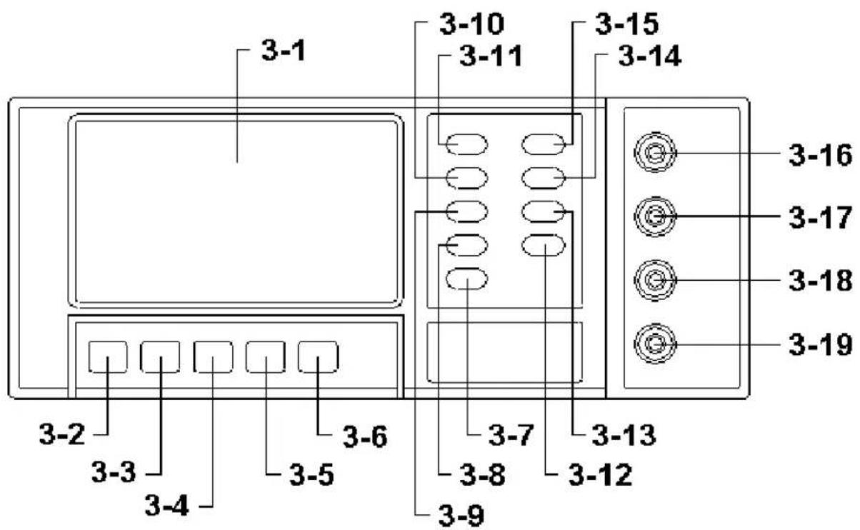
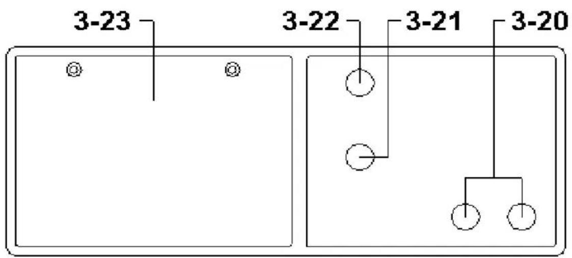
Fig. 1
MARKS:
$$ \text { On } = 1, \text { Off } = 0 $$
$$ A C = \sim , D C = - - - $$
3-1 LCD Display
3-2 Power Switch
3-3 AC V/A/WATT Switch
3-4 DC V/A Switch
3-5 Ohm Switch
3-6 Current In Switch
3-7 WATT/VA/Whr Button
3-8 Whr Zero Button
3-9 COS θ (power factor)/Hz Button
3-10 Peak Hold Button
3-11 Data Hold Button
3-12 Current Mode Button
3-13 " ^ " Button ( Alarm Set )
3-14 " > " Button ( Alarm Set )
3-15 Alarm Set Button
3-16 Watt Terminal
3-17 V/Ohm Terminal
3-18 COM Terminal
3-19 Current Terminal
3-20 Clamp-On Current Input Terminals
3-21 DC 9V Power Adapter Input Socket
3-22 RS-232 Output Terminal
3-23 Battery Cover/Battery Compartment
4. PRECAUTIONS & PREPARATIONS FOR MEASUREMENT
1) Ensure that the batteries are connected correctly to their snap terminals and placed in the battery compartment.
2) Select & push the correct Switch & button before marking measurements
3) Place the Test Lead into the proper input terminal before marking measurements.
4) Remove either of the test leads from the circuit under test while changing the measurement function.
5) Operate the instrument only in the ambient temperature range of 0 to 50 (32 to 122 °C) and less than 80% Relative humidity.
6) Do not exceed the maximum rated voltage of each range and input terminal.
7) Always switch the power to its "Off" position when the instrument is not in use. Remove the batteries if not intend to use the instrument for a long period of time.
5. MEASURING PROCEDURE

Caution :
* Do not apply the overload voltage, current to the input terminal!
5-1 AC Watt/ V/ A/ PF/ Hz Measurement
1) Push the "Power switch" (3-2, Fig. 1) to "On" position.
$$ \mathrm{On} = 1, \mathrm{Off} = 0 $$
2) Select the "AC V/A/WATT Switch" (3-3, Fig. 1).
3) Select the " Current In Switch " ( 3-6, Fig. 1 ) to the " DIRECT " position.
4) Power off the "Power Source" of the measured installation.
Make the wire connection and connect the test leads into terminals ( 3-16, 3-17, 3-18, 3-19 ) as the Fig. 2
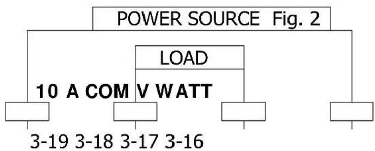
flowchart
graph TD
    A["POWER SOURCE Fig. 2"] --> B["LOAD"]
    B --> C["10 A COM V WATT"]
    C --> D["3-19 3-18 3-17 3-16"]
    C --> E["Output Line"]
For example : The wire connection for measuring the power of " Electrical Bulb "
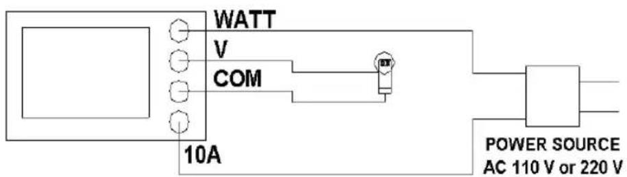
6) * Connect the "LOAD" to the terminals of 3-17, 3-18, refer Fig. 2.
* Connect the "POWER SOURCE" to the terminals of 3-16, 3-19, refer Fig. 2.
7) Power on the "Power Source" of the measured installation.
The "LCD display" (3-1, Fig. 1) will show the Watt, Voltage, Current, PF (Power Factor) at the same time.
* Watt function is the true power ( V x A x PF ) measurement.
* Voltage & Current function is the true rms measurement.
* For the Watt measurement, the max. input current should less than ACA 10A.
Line frequency ( Hz ) measurement :
8) During the Watt measurement, push the "PF/Hz Button" (3-9, Fig. 1) once, will show Line frequency value instead of the PF value.
* Push the "PF/Hz Button" again, the Hz value will disappear & the PF value will display again.
5-2 AC VA/ V/ A/ PF/ Hz Measurement
All the measuring procedures are same as the above "5-1 AC Watt/V/A/PF/Hz Measurement" except should push the "WATT/VA/Whr Button" (3-7, Fig. 1) once, then the display will show the VA, voltage, current, Hz at the same time.
* The VA function is the apparent power (V x A) measurement.
* During the VA measurement, the LCD will show VA, Voltage, Current & Hz, it can not show the value of PF (Power Factor).
5-3 AC Watt Hour ( Whr ) Measurement
All the measuring procedures are same as the above "5-1 AC Watt/V/A/PF/Hz Measurement" except should push the "WATT/VA/Whr Button" (3-7, Fig. 1) twice, then the display will show the Whr value along with the elapsed time.
* The Whr (Watt Hour) is the value of Watt x hour.
* The Whr measurement will start at the moment after the "Whr" unit is displayed on the LCD display.
* The display of Whr measurement will stop ( hold ) when push the " Data Hold Button " ( 3-5, Fig. 1 ) once. Push the " Data Hold Button " once again will continue the Whr function.
* Press "Whr Zero Button" (3-8, Fig. 1) once will "reset (zero)" the Whr measuring value and make the new measurement again.
5-4 AC Voltage, AC Current Measurement
1) Push the "Power switch" (3-2, Fig. 1) to "On" position.
$$ \mathrm{On} = 1, \mathrm{Off} = 0 $$
2) Select the "AC V/A/WATT Switch" (3-3, Fig. 1).
3) Select the "Current In Select Switch" (3-6, Fig. 1) to the "DIRECT" position.
4) AC Voltage measurement
a. Connect red test lead to "V/Ohm Terminal" (3-17, Fig. 1) and black test lead to "COM Terminal" (3-18, Fig. 1).
b. Connect test lead probes into circuit under test.
c. The display will show the AC voltage directly.
5) AC Current measurement
a. Connect red test lead to " Current ( 10 A ) Terminal "( 3-19, Fig. 1 ) and black test lead to " COM Terminal"( 3-18, Fig. 1 ).
b. Open the circuit in which current is to be measured. Now securely connect test leads in series with the load which the current is be measured.
c. The display will show the AC current directly.
* The max. AC current input value should less than 10 A.
5-5 DC Voltage, DC Current Measurement
1) Push the "Power switch" (3-2, Fig. 1) to "On" position.
$$ \text { On } = 1, \text { Off } = 0 $$
2) Select the "DC V/A Switch" (3-4, Fig. 1).
3) Select the "Current In Select Switch" (3-6, Fig. 1) to the "DIRECT" position.
4) DC Voltage measurement
a. Connect red test lead to "V/Ohm Terminal" (3-17, Fig. 1) and black test lead to "COM Terminal" (3-18, Fig. 1).
b. Connect test lead probes into circuit under test.
c. The display will show the DC voltage directly.
Remark :
When the "DC" mark on the LCD be flashed, it means the measured display value is negative DC voltage.
5) DC Current measurement
a. Connect red test lead to "Current (10 A) Terminal" (3-19, Fig. 1) and black test lead to "COM Terminal" (3-18, Fig. 1).
b. Open the circuit in which current is to be measured. Now securely connect test leads in series with the load which the current is be measured.
c. The display will show the DC current directly. * The max. DC current input value should less than 10 Ampere.
5-6 Ohm Measurement
1) Push the "Power switch" (3-2, Fig. 1) to "On" position.
On = 1, Off = 0
2) Select the "Ohm Switch" (3-5, Fig. 1).
3) Connect red test lead to " V/Ohm Terminal " ( 3-17, Fig. 1 ). and black test lead to " COM Terminal " ( 3-18, Fig. 1 ).
4) If the resistance being measured is connected to a circuit, turn off power to circuit being tested and discharge all capacitors.
5) Connect test lead probes into circuit (resistance) under test.
6) Read resistance value on digital display.
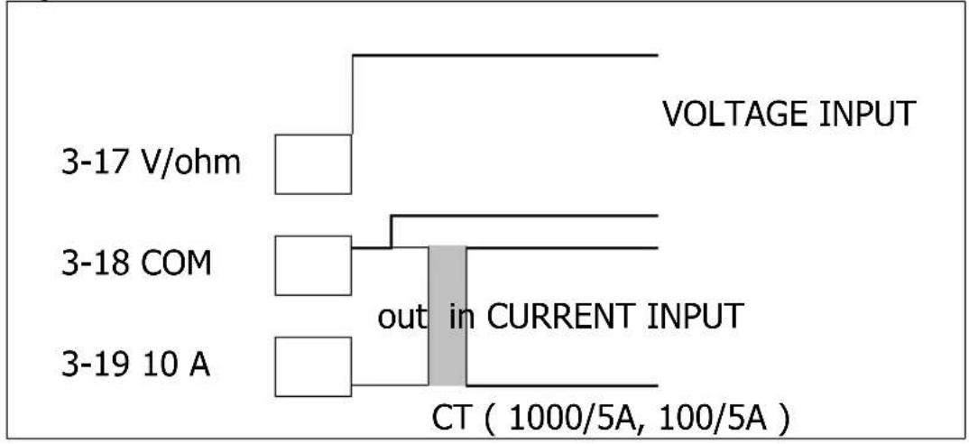
5-7 AC Watt, VA, Whr measurement, current input cooperate with CT (current transformer)
Other measurement procedures are same as the 5-1, 5-2, except :
1) Wire connection as following, ref. Fig. 3
Voltage : " V Terminal " ( 3-17, Fig. 3 ) & " COM terminal " ( 3-18, Fig. 3 )
Current : Current transformer output connect to the "10A Terminal" (3-19, Fig. 3) & "COM terminal" (3-18, Fig. 3)
2) Select the CT type, 100/5A or 1000/5A by push the "Current Mode Button" (3-12, Fig. 1). The LCD will show the marker "CT 100/5A", "CT 1000/5A" when the CT type is selected.
Fig. 3
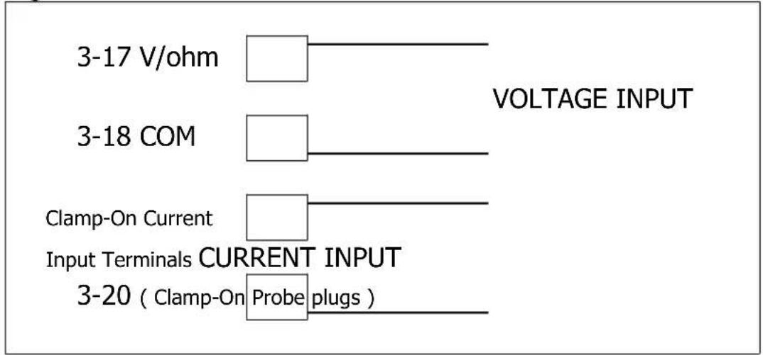
5-8 AC Watt, VA, Whr measurement, current input cooperate with Clamp-On Probe
Other measurement procedures are same as the 5-1, 5-2,
except :
1) Wire connection, ref. Fig. 4
Voltage :
" V Terminal " ( 3-17, Fig. 4 ) & " COM terminal "( 3-18, Fig. 4 )
Current :
The output plug of the inductive current probe (1 ACmV per 1 ACA, such as PCE-CA-502) connect to the "Clamp-On Current Input Terminals" (3-20, Fig. 4).
2) It should select the " Current In Switch " ( 3-6, Fig. 1 ) to the " CLAMP-ON " position, the display will show the marker " clamp1000A ".
Fig. 4
5-9 Data Hold
During the measurement, Push the " Data Hold Button " ( 3-11, Fig. 1 ) will hold the display values & LCD will show the " HOLD " marker.
* Push the "Data Hold Button" again will release the DATA HOLD function.
* Data hold function is not available for ohm range.
5-10 Peak Hold
During the measurement, Push the " Peak Hold Button " ( 3-10, Fig. 1 ) will hold the peak measurement values & LCD will show the " PK.H " marker.
Peak Hold function only available for the "Watt value"
* Push the " Peak Hold Button " again will release the PEAK HOLD function.
5-11 Alarm Setting
1) Alarm setting function only for the "Watt" & "VA" display value.
2) " Alarm Set Button " ( 3-15 ) is used to set the Max., Min. alram value or set the alarm off ( display not show Max., Min. marker when adjust the Alarm Set Button ).
3) " > Button " ( 3-13, Fig. 1 ) is used to select the digit.
4) " ^ Button " (3-14, Fig. 1) is used to select the value (0, 1, 2.....9) of each digit.
5) The buzzer will alarm when the Watt or VA alarm setting value larger than the " Max. " value or smaller than " Min. " value.
6. MAINTENANCE
Caution :
* Risk of electric shock!
* Remove power cord before open the battery cover!

6-1 Battery Replacement
1) When the LCD display shows the "BAT" marker, it is necessary to replace the batteries. However, in-spec. measurement may still be made for several hours after appear low battery indicator.
2) Loose the screw, slide the Battery Cover (3-23, Fig. 1), away from the instrument and remove the batteries.
3) Replace the 6 x 1.5 V AA (UM-3) batteries and reinstate the cover.
6-2 Cleaning

* Cleaning - Only use the dry cloth to clean the plastic case!
7. RS232 PC SERIAL INTERFACE
The instrument features an RS232 output via 3.5 mm Terminal (3-22, Fig. 1).
The connector output is a 16 digit data stream which can be utilized to the user's specific application.
An RS232 lead with the following connection will be required to link the instrument with the PC serial input.
Meter PC
(3.5 mm jack plug) (9W 'D" Connector)
Center Pin.... Pin 4
(3.5 mm jack plug)
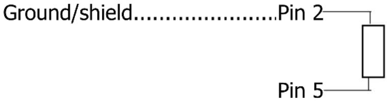
2.2 K
resistor
The 16 digit data stream will be displayed in the following format :
| D0 End Word | |
| D1 & D8 Display reading, D1 = LSD, D8 = MSDFor example:If the display reading is 1234, then D8 to D1 is :00001234 | |
| D9 Decimal Point(DP), position from right to the left0 = No DP, 1= 1 DP, 2 = 2 DP, 3 = 3 DP | |
| D10 Polarity | 0 = Positive 1 = Negative |
| D11 & D12 Annunuciator for Display | |||
| D13 1 = Top to show display position | left display 2 = Top right display | ||
| 3 = Bottom left display 4 = Bottom right display | |||
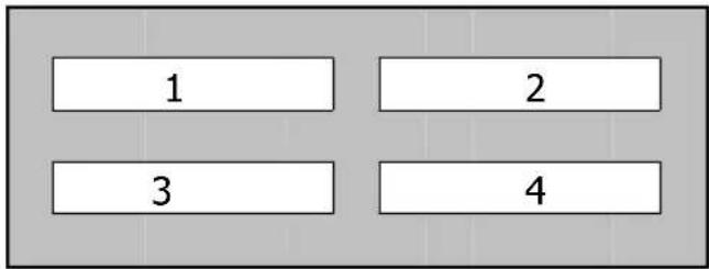 | DISPLAY | ||
| D14 4 | |||
| D15 Start Word | |||
RS232 FORMAT : 9600, N, 8, 1
| Baud rate | 9600 |
| Parity | No parity |
| Data bit no. | 8 Data bits |
| Stop bit | 1 Stop bit |

- POWER ANALYZER USA From outside US: +1 Tel: (561) 320-9162 Fax: (561) 320-9176 info@pce-americas.c www
- Caution Symbol
- Caution :
- Environment Conditions
- TABLE OF CONTENTS
- FEATURES
- SPECIFICATIONS
- Remark :
- FRONT PANEL DESCRIPTION
- MARKS:
- PRECAUTIONS & PREPARATIONS FOR MEASUREMENT
- MEASURING PROCEDURE
- 5-1 AC Watt/ V/ A/ PF/ Hz Measurement
- Line frequency ( Hz ) measurement :
- 5-2 AC VA/ V/ A/ PF/ Hz Measurement
- 5-3 AC Watt Hour ( Whr ) Measurement
- 5-4 AC Voltage, AC Current Measurement
- 5-5 DC Voltage, DC Current Measurement
- 5-6 Ohm Measurement
- 5-7 AC Watt, VA, Whr measurement, current input cooperate with CT (current transformer)
- 5-8 AC Watt, VA, Whr measurement, current input cooperate with Clamp-On Probe
- Voltage :
- Current :
- 5-9 Data Hold
- 5-10 Peak Hold
- Peak Hold function only available for the "Watt value"
- 5-11 Alarm Setting
- MAINTENANCE
- 6-1 Battery Replacement
- 6-2 Cleaning
- RS232 PC SERIAL INTERFACE
Brand : PCE
Model : PA6000
Category : Measurement