
Prestige RTGH-RH11DVLN - Instant water heater and water tank Rheem - Free user manual and instructions
Find the device manual for free Prestige RTGH-RH11DVLN Rheem in PDF.


| Type | Tankless Gas Water Heater |
| Brand | Rheem |
| Model | Prestige RTGH-RH11DVLN |
| Dimensions (W x H x D) | 17.3" x 28.7" x 14.8" (439 mm x 728 mm x 376 mm) |
| Weight | 85 lbs (38.6 kg) |
| Power Supply | 120V 60Hz, 172W max consumption |
| Gas Input (Max/Min) | 199,000 / 18,000 Btu/h (Natural Gas) |
| Hot Water Capacity (35°F rise) | 11.0 GPM |
| Water Connections | 3/4" NPT (DHW inlet, outlet, recirculation return) |
| Gas Connection | 3/4" NPT |
| Venting | Direct vent, 2" or 3" Schedule 40 PVC, CPVC, PP |
| Max Vent Length (2"/3") | 50 ft / 100 ft |
| Minimum Flow Activation | 0.5 GPM |
| Gas Supply Pressure (NG) | 5.0" - 10.5" W.C. |
| Gas Supply Pressure (LP) | 9.5" - 13.0" W.C. |
| Heat Exchanger Material | STS 304 Stainless Steel |
| Control Panel | P-950C with LCD display |
| Safety Devices | Flame sensor, overheat limit, gas leak detector, water leak detector |
| Freeze Protection | Built-in, activates at 46°F (pump) and 41°F (burner) |
| Pressure Relief Valve | 3/4", 150 psi (ASME certified) |
| Installation | Indoor, wall hung, minimum 18" above garage floor |
| Warranty (Residential) | 12 years heat exchanger, 5 years parts, 1 year labor |
| Included Items | Heater, manual, wall bracket, vent screens, isolation valve, pressure relief valve, emergency kit |
| Low Lead Compliance | Complies with Safe Drinking Water Act Section 1417 |
Frequently Asked Questions - Prestige RTGH-RH11DVLN Rheem
User questions about Prestige RTGH-RH11DVLN Rheem
0 question about this device. Answer the ones you know or ask your own.
Ask a new question about this device
Download the instructions for your Instant water heater and water tank in PDF format for free! Find your manual Prestige RTGH-RH11DVLN - Rheem and take your electronic device back in hand. On this page are published all the documents necessary for the use of your device. Prestige RTGH-RH11DVLN by Rheem.
USER MANUAL Prestige RTGH-RH11DVLN Rheem
NOTE TO CONSUMER: DO NOT DESTROY THIS MANUAL. PLEASE READ CAREFULLY AND KEEP ALL INSTRUCTIONS FOR FUTURE REFERENCE.
The surfaces of these products contacted by consumable water contain less than 0.25% lead by weight, as required by the Safe Drinking Water Act, Section 1417.
WARNING
If the information in these instructions is not followed exactly, a fire or explosion may result, causing property damage, personal injury, or death.
FOR YOUR SAFETY!
- Do not store or use gasoline or other flammable vapors and liquids in the vicinity of this or any other appliance. To do so may result in an explosion or fire.
• Installation and service must be performed by a qualified installer, service agency, or the gas supplier.
WHAT TO DO IF YOU SMELL GAS
- Do not try to light any appliance.
- Do not touch any electrical switch; do not use any phone in your building.
- Immediately call your gas supplier from a neighbor's phone. Follow the gas supplier's instructions.
- If you cannot reach your gas supplier, call the fire department.
- Do not return to your home until authorized by the gas supplier or fire department.
This water heater is not suitable for use in manufactured (mobile) homes.
WARNING : If you do not follow these instructions exactly, a fire or explosion may result causing property damage, personal injury or loss of life.
A. This appliance does not have a pilot. It is equipped with an ignition device which automatically lights the burner. Do not try to light the burner by hand.
B.BEFORE OPERATING smell all around the appliance area for gas. Be sure to smell next to the floor because some gas is heavier than air and will settle on the floor.
WHAT TO DO IF YOU SMELL GAS
- Do not try to light any appliance. -Do not touch any electric switch; do not use any phone in your building. -Immediately call your gas supplier from a neighbor's phone. Follow the gas supplier's instructions. -If you cannot reach your gas supplier, call the fire department. -Do not return to your home until authorized by the gas supplier or fire department.
C. Use only your hand to push in or turn the gas control knob. Never use tools. If the knob will not push in or turn by hand, don't try to repair it, call a qualified service technician. Force or attempted repair may result in a fire or explosion.
D.Do not use this appliance if any part has been under water. Immediately call a qualified service technician to inspect the appliance and to replace any part of the control system and any gas control which has been under water.
OPERATING INSTRUCTIONS
1.STOP! Read the safety information above on this label.
2. Turn off all electric power to the appliance.
3.Do not attempt to light the burner by hand.
4. Turn the Gas Shutoff Valve located on the outside of the unit clockwise ircledcirc to the "OFF" position.
GAS SHUTOFF VALVE
5. Wait five (5) minutes to clear out any gas. If you then smell gas, STOP! Follow "B" in the safety information above on this label. If you don't smell gas, go to the next step.
6. Turn the Gas Shutoff Valve located on the outside of the unit counterclockwise ∩ to the "ON" position.
7. Turn on all electric power to the appliance.
8. If the appliance will not operate, follow the instructions "To Turn Off Gas To Appliance" and call your service technician or gas supplier.

OPEN

CLOSE
TO TURN OFF GAS TO APPLIANCE
- Turn off all electric power to the appliance if service is to be performed.
- Turn the Gas Shutoff Valve located on the outside of the unit clockwise Ⓞ to the "OFF" position.
The following defined terms are used throughout this manual to bring attention to the presence of hazards of various risk levels, or to important product information.
! DANGER
DANGER indicates an imminently hazardous situation which, if not avoided, will result in death or serious injury.
WARNING
WARNING indicates a potentially hazardous situation which, if not avoided, could result in death or serious injury.
CAUTION
CAUTION indicates a potentially hazardous situation which, if not avoided, may result in minor or moderate injury.
IMPORTANT
IMPORTANT is used to indicate a potentially hazardous situation which, if not avoided, may result in property damage, FOR YOUR SAFETY is used to indicate specific safety related instructions or procedures, and NOTICE is used to address practices not related to personal injury.
WARNING
California Proposition 65 Warning: This product contains chemicals known to the State of California to cause cancer birth defects, or other reproductive harm.


- FOREWORD
This manual is intended to be used in conjunction with other literature provided with the water heater. This includes all related control information. It is important that this manual, all other documents included with this system, and additional publications including the National Fuel Gas Code, ANSI Z223.1-2002, be reviewed in their entirety before beginning any work.
Installation should be made in accordance with the regulations of the Authority Having Jurisdiction, local code authorities, and utility companies which pertain to this type of water heating equipment.
Authority Having Jurisdiction (AHJ) – The Authority Having Jurisdiction may be a federal, state, local government, or individual such as a fire chief, fire marshal, chief of a fire prevention bureau, labor department or health department, building official or electrical inspector, or others having statutory authority. In some circumstances, the property owner or his/her agent assumes the role, and at government installations, the commanding officer or departmental official may be the AHJ.
NOTE: Rheem reserves the right to modify product technical specifications and components without prior notice.
- FOR THE INSTALLER
! DANGER
This manual must only be used by a qualified heating installer/service technician. Read all instructions in this manual before installing. Perform steps in the order given. Failure to comply could result in substantial property damage, severe personal injury, or death.
This appliance must be installed by qualified and licensed personnel. The installer should be guided by the instructions furnished with the water heater, and with local codes and utility company requirements. In the absence of local codes, preference should be given to the National Fuel Gas Code, ANSI Z223.1-2002.
INSTALLATIONS MUST COMPLY WITH:
Local, state, provincial, and national codes, laws, regulations and ordinances.
The latest version of the National Fuel Gas Code, ANSI Z223.1, from American Gas Association Laboratories, 8501 East Pleasant Valley Road, Cleveland, OH 44131.
In Canada – CGA No. B149 (latest version), from Canadian Gas Association Laboratories, 55 Scarsdale Road, Don Mills, Ontario, Canada M3B 2R3. Also, Canadian Electrical Code C 22.1, from Canadian Standards Association, 5060 Spectrum Way, Suite 100, Mississauga, Ontario, Canada L4W 5N6.
Code for the installation of Heat Producing Appliances (latest version), from American Insurance Association, 85 John Street, New York, NY 11038.
The latest version of the National Electrical Code, NFPA No. 70.
NOTE: The gas manifold and controls met safe lighting and other performance criteria when the water heater underwent tests specified in ANSI Z21.10.3 – latest edition.
TABLE OF CONTENTS
USER'S INFORMATION......7
A. PRODUCT AND SAFETY INFORMATION....7
- BEFORE OPERATION....8
- DURING OPERATION......8
- TROUBLESHOOTING AND GENERAL CAUTIONARY STATEMENTS....9
B. MAINTENANCE....10
- SERVICE TECHNICIAN....10
- OWNER MAINTENANCE....10
C. MAINTENANCE PROCEDURES....11
- DAILY MAINTENANCE....11
- MONTHLY MAINTENANCE....11
- 6 MONTH MAINTENANCE....12
- ANNUAL MAINTENANCE....13
D. TROUBLESHOOTING....13
THE FOLLOWING ARE INSTALLATION INSTRUCTIONS FOR THE CONTRACTOR....14
ITEMS SHIPPED WITH THE WATER HEATER....15
SAFETY REGULATIONS....15
A. OPERATION AND INSTALLATION WARNINGS....15
B. IMPROPER COMBUSTION....16
C. GAS....16
D. WHEN SERVICING THE WATER HEATER....17
E. WATER CHEMISTRY REQUIREMENTS....17
F. FREEZE PROTECTION....17
G. SCALDING....18
H. HIGH ELEVATION INSTALLATIONS....18
SPECIFICATIONS....19
A. SPECIFICATIONS....19
B. COMPONENTS....20
C. DIMENSIONS....21
PREPARE WATER HEATER LOCATION....22
A. BEFORE LOCATING THE WATER HEATER....22
B. LEVELING....23
C. CLEARANCES FOR SERVICE ACCESS....23
D. RESIDENTIAL GARAGE AND CLOSET INSTALLATIONS....23
E. EXHAUST VENT AND INTAKE PIPE.... 24
F. CARBON MONOXIDE DETECTORS....24
G. PREVENT COMBUSTION AIR CONTAMINATION....24
H. REMOVING A WATER HEATER FROM A COMMON VENT SYSTEM....25
I. UNPACKING THE WATER HEATER....25
J. WALL-MOUNTING THE WATER HEATER....26
VENTING....27
A. INTAKE PIPE AND EXHAUST VENT GUIDELINES....27
B. APPROVED VENT MATERIALS....30
C. ALLOWED SCHEDULE 40 VENT LENGTHS (PVC, CPVC, PP)....31
D. TIGHTENING WATER HEATER COLLAR TO EXHAUST VENT AND INTAKE PIPE....32
E. VENT TERMINATION....32
- Direct Vent, Two Pipe Roof and Sidewall Vent Terminations....33
- Direct Vent, Optional Horizontal and Vertical Vent Kits....33
- Screen Installation....33
- Power Venting, Indoor Combustion Air Installation in Confined or Unconfined Space....34
F. COMMON VENT PIPING....36
- VENT DIAMETER SIZING AND LENGTHS....36
- RECOMMENDED EXHAUST PIPE TRANSITIONS....37
- TWO PIPE VENT SYSTEM (DIRECT VENT)....38
INSTALL THE CONDENSATE DRAIN....38
GAS PIPING....40
A. GAS PIPE SIZING TABLES....40
- Gas Pipe Sizing....40
- Natural Gas Pipe Sizing....40
- LP (Liquid Propane) Gas Pipe Sizing....41
B. GAS CONNECTION REQUIREMENTS....42
C. ADDITIONAL PRECAUTION FOR EXCESS FLOW VALVE (EFV)......43
D. ADJUSTING GAS PRESSURE AT THE WATER HEATER....43
E. SETTING AND VERIFYING THE COMBUSTION SETTING....43
WATER PIPING 44
A. GENERAL PLUMBING CONNECTION GUIDELINES....44
B. INSTALL A BACKFLOW PREVENTER.... 46
C. PIPING THE WATER HEATER....46
D. APPLICATIONS......46
E. PRESSURE RELIEF VALVE....49
CONNECT ELECTRICAL POWER / INITIAL STARTUP....50
A. WIRING INFORMATION......50
B. DIP SWITCHES....51
OPERATING SYSTEM INSTRUCTIONS....57
A. CONTROL PANEL....57
B. LCD DISPLAY DESCRIPTIONS....57
C. START-UP SEQUENCE....58
D. CHANGING THE DHW SET-POINT....58
E. STATUS DISPLAY MODE....59
F. CHANGING THE TIME....60
G. INSTALLER MODE....61
H. USING RECIRCULATION MODES - STEP 1....62
I. SETTING THE RECIRCULATION TIMER – USING RECIRCULATION MODES – STEP 2....63
- Set the Recirculation Timer Type....64
- Setting the Recirculation Run Time (Pro9 Recirculation Timer)....65
- Resetting the Recirculation Run Time....66
J. ERROR MODE....67
K. ERROR TREE ANALYSIS......67
- FLAME DETECTION....71
- GAS DETECTION....72
- AIR PRESSURE SWITCH....72
- Inlet / DHW / Operating Temperature Sensors....73
FINAL INSTALLATION CHECKLIST....74
TROUBLESHOOTING....76
DIAGNOSTICS AND SUGGESTED CORRECTIVE ACTIONS ....76
MAINTENANCE PROCEDURES....77
REPLACEMENT PARTS....81
Limited Warranty for 180,000 / 199,000Btu/hr Tankless Water Heaters....82
MAINTENANCE REPORT......84
MAINTENANCE NOTES......85
CUSTOMER INSTALLATION RECORD FORM....86
USER'S INFORMATION
• A. PRODUCT AND SAFETY INFORMATION
 |
| USER – Have this water heater serviced/inspected by a qualified service technician annually. |
| FAILURE TO ADHERE TO THE GUIDELINES IN THIS MANUAL CAN RESULT IN SUBSTANTIAL PROPERTY DAMAGE, SEVERE PERSONAL INJURY, OR DEATH. |

OPERATING INSTRUCTIONS
- STOP! DO NOT use this water heater unless it is completely filled with water.
- Ensure electrical power to the water heater is turned OFF.
- This water heater is equipped with an ignition device which automatically lights the burner. DO NOT attempt to light the burner by hand.
- Turn the gas shut-off valve clockwise to the "OFF" position. Do not force.
- Wait five (5) minutes to clear out any gas. If you smell gas, STOP! Follow the information on page 2, this manual. If you don't smell gas, go to the next step.
- Turn manual gas shut-off valve to the "ON" position.
- Turn ON electrical power to the water heater.
- Wait until default temperature (120°F/49°C) is displayed. Set desired water temperature.
- If the water heater will not operate, follow the instructions on page 2 to turn off the gas to the water heater. Then call your service technician or gas supplier.
TO TURN OFF GAS TO THE WATER HEATER
- Set the thermostat to the lowest setting.
- Turn off all electrical power to the water heater.
- Turn manual gas shutoff valve to "OFF".

| Proper care of this water heater is the user's / owner's responsibility. The user / owner should carefully read and understand the Operating Information in this manual before operating this water heater. |
| It is the user / owner's responsibility to know the location of the gas shut-off valve and how to operate it. Immediately close the gas shut-off valve if the water heater is subjected to fire, overheating, flood, physical damage, or any other damaging condition that might affect the operation of the unit. Have the water heater checked by a qualified technician before resuming operation. |
| DO NOT use this water heater if ANY part has been under water. Immediately call a qualified technician to inspect the water heater and replace any part of the control system or gas control which has been under water. |
| DO NOT power up the water heater unless the gas and water supply valves are fully opened. Make sure the fresh air intake pipe and exhaust vents are open and functional. |
| DO NOT attempt to install, repair, or service this water heater. Contact a qualified technician if the water heater needs repair or maintenance. Ask your gas supplier for a list of qualified service providers. |
| DO NOT use spray paint, hair spray, or any other flammable sprays near the water heater or near the exterior fresh air intake pipe termination. DO NOT place any items in or around the exterior exhaust vent termination and/or fresh air intake pipe that could restrict or block the flow in or out of the vent system. |
| All safety devices must be tested after the water heater is installed. |
| Always verify proper water heater operation after servicing. |
| The gas ignition system components must be protected from water (dripping, spraying, rain, etc.) during water heater operation and service (circulator replacement, condensate trap, control replacement, etc.) |
| The E80 code will display when there is no water in the water heater. Ensure the water heater is full of water. Then manually reset the water heater to resume operation. |
| This water heater features a factory installed overheating prevention device. This limit provides water heater shutdown in the event that the water heater water temperature exceeds the set point of the limit control. Certain local codes require additional water temperature limiting devices. |
| Failure to follow these warnings could result in property damage, personal injury, or death. |
- 1. BEFORE OPERATION
- Check the Gas Type (NG/LP)
When operating the water heater for the first time, ensure the connected gas type matches that of the gas type of the water heater. Check whether the gas supplied is NG or LP. The water heater gas type is indicated on the rating plate on the side of the water heater. - Check the Power (120V 60Hz)
Ensure the water heater is connected to a properly rated power supply. - Check the Cold Water Inlet Valve
Ensure the cold water inlet valve is open when operating the water heater. The water heater will not operate if there is insufficient water supply. - Check the Gas Valve
Ensure the manual shut-off gas valve is open. The water heater will not operate unless it is supplied with gas. - Check the Area around the Water heater
Remove any combustible or flammable materials from the area around the water heater and do not hang wet laundry from the exhaust vent pipe.
WARNING
Attempting to operate this water heater on a gas supply other than specified on the rating plate will result in improper water heater operation, and could result in property damage, personal injury, or death.
! DANGER
Do not operate the water heater if its combustion air intake is located in or near one of the areas or in the vicinity of products listed in Table 1. These areas will always contain hazardous contaminants that can form strong acids while passing through the burner and vent system. These acids will corrode the water heater's heat exchanger, burner components and vent system, resulting in flue gas spillage and/or water leakage, possible substantial property damage, severe personal injury, or death. If the water heater combustion air intake is located in any area likely to cause or contain contamination, or if products which would contaminate the air cannot be removed, the intake must be re-piped and terminated to another location.
DO NOT re-pipe ventilation system on your own. Call a qualified service provider for assistance.
| PRODUCTS TO AVOID AREAS LIKELY TO HAVE CONTAMINANTS | |
| Spray cans containing fluorocarbons Dry cleaning/laundry areas and establishments | |
| Permanent wave solutions Swimming pools | |
| Chlorinated waxes/cleaners Metal fabrication plants | |
| Chlorine-based swimming pool chemicals Beauty shops | |
| Calcium chloride used for thawing Refrigeration repair shops | |
| Sodium chloride used for water softening Photo processing plants | |
| Refrigerant leaks Auto body shops | |
| Paint or varnish removers Plastic manufacturing plants | |
| Hydrochloric or Muriatic acid Furniture refinishing areas and establishments | |
| Cements and glues New building construction | |
| Antistatic fabric softeners used in clothes dryers Remodeling areas | |
| Chlorine-type bleaches, laundry detergents, and cleaning solvents | Garages and workshops |
| Adhesives used to fasten building products |
Table 1
- 2. DURING OPERTAION
1. Check for Gas Leaks
Frequently check the gas pipe and connections for leaks with a soapy solution. If air bubbles appear during the test, gas is leaking out. Close the gas supply valve and call your gas supplier for inspection.
WARNING
After any repair of the gas pipeline or replacement of the gas regulator, call a qualified service technician to observe the installation and replacement before restoring power to the water heater. Failure to do so could result in a fire or explosion, substantial property damage, severe personal injury, or death.
2. Check for Proper Ventilation
Ensure there is sufficient ventilation while operating the water heater. Improper ventilation could result in premature water heater failure. Such failures ARE NOT covered by water heater warranty.
WARNING
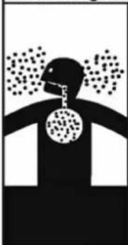
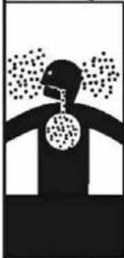
Breathing Hazard - Carbon Monoxide Gas
natural_image
Silhouette of a human head with a circular object suspended, emitting particles above (no text or symbols)- Do not operate heater if flood damaged.
• Install vent system in accordance with local codes and manufacturers installation instructions. - Do not obstruct heater air intake or exhaust. Support all vent piping per manufacturers installation instructions.
- Do not place chemical vapor emitting products near unit.
- According to NFPA 720, carbon monoxide detectors should be installed outside each sleeping area.
- Never operate the heater unless it is vented to the outdoors.
- Analyze the entire vent system to make sure that condensate will not become trapped in a section of vent pipe and therefore reduce the open cross sectional area of the vent.
Breathing carbon monoxide can cause brain damage or death. Always read and understand instruction manual.
WARNING
Exhaust gas entering the living space can cause carbon monoxide poisoning. If exhaust gas should leak into the living space:
- Shut down the water heater.
- Close the gas valve.
- Open windows for ventilation.
Immediately call a qualified service technician to inspect the water heater and exhaust vent pipe. Any damages to the exhaust vent pipe should be repaired immediately. Failure to do so could result in substantial property damage, severe personal injury, or death.
3. Burn Warning
Take caution when inspecting the water heater, exhaust vent, and/or water pipes. These components can get extremely hot during water heater operation.
4. Combustibles and Flammable Material Warning
Do not store combustibles or flammable materials in the vicinity of this water heater. Do not hang clothes from the exhaust pipe.
WARNING
Storing flammable or combustible materials near this water heater could result in a fire or explosion, substantial property damage, severe personal injury, or death.
5. Check for Water Leaks
- Do not attempt to clean the heating system. Call a qualified service technician for service.
- If you notice any leaks, immediately call a qualified service technician. Leaks in water heater or piping must be repaired at once.
- 3. TROUBLESHOOTING AND GENERAL CAUTIONARY STATEMENTS
DO NOT use this water heater for any purposes other than those specifically described by Rheem (to provide domestic hot water). Using this water heater for unapproved purposes WILL VOID the warranty, and could result in property damage, serious personal injury, or death.
WARNING
| DO NOT wipe the water heater or control panel with a wet cloth. Doing so may result in an electric shock, substantial property damage, premature water heater failure, severe personal injury, or death. |
| DO NOT shut off the water heater for long periods of time during potentially freezing conditions. This water heater has a freeze protection function. The ceramic heater installed inside of the heater's heat exchanger is designed to protect the water heater from freezing. |
| Ensure the exposed water pipes are thermally insulated to prevent damage due to freezing conditions. If the water heater is not to be used for an extended period of time during freezing conditions, shut down the system and completely drain the water heater. |
If the water heater is not to be used for an extended period of time during freezing conditions, consider shutting down the system and draining it of water. Shut off the gas and cold water supply valves.
WARNING
DO NOT attempt to disassemble this water heater. Doing so could result in improper water heater operation or premature water heater failure, substantial property damage, and/or severe personal injury or death due to electric shock, fire, or explosion. If repairs are required, contact a qualified service technician.
CAUTION
DO NOT touch the exhaust vent or hot water pipes during water heater operation. Doing so could result in substantial personal injury.
DANGER
Be careful when opening a hot water faucet or draining water from the water heater. Water temperature over 125irc F can instantly cause severe burns, or death, from scalds. Children, disabled, and elderly are at the highest risk of being scalded. See instruction manual before setting temperature at water heater. Feel water before bathing or showering!
B. MAINTENANCE
1. SERVICE TECHNICIAN
The following maintenance should be performed by a qualified service technician annually:
General
- Attend to any reported problems.
- Inspect the interior of the water heater cabinet; clean and vacuum if necessary.
- Clean the condensate trap and fill with fresh water.
- If applicable, check the condensate neutralizer and ensure it is full of condensate neutralizing marble chips.
- Check for leaks: Water, gas, flue and condensate.
- Verify exhaust vent and intake piping are in good condition and sealed tight.
- Check exhaust vent and intake pipe bracing. Ensure bracing is undamaged and in good condition.
- Check water heater water pressure, piping and expansion tank.
- Check control settings.
- Check ignition electrode. Sand off any white oxide. Clean and reposition.
- Check ignition and ground wiring.
- Check all control wiring and connections.
- Check burner flame pattern (stable and uniform).
Additional Items if Combustion or Performance is Poor
- Clean heat exchanger and flue ways.
- Remove burner assembly and clean burner head using compressed air only.
Once the maintenance items are completed, the service technician should review service with the owner.
2. OWNER MAINTENANCE
Periodically
- Check area around the water heater.
- Check and remove any blockage from the outdoor exhaust vent and intake pipe terminations. DO NOT perform this maintenance if exhaust vent and intake pipe terminations are in difficult to reach locations.
- Check the temperature/pressure gauge.
Monthly
- Check exhaust vent and intake piping.
- Check exhaust vent and intake pipe bracing. Ensure bracing is undamaged and in good condition.
- Check the pressure relief valve.
- Check the condensate drain system.
- If applicable, check the condensate neutralizer and ensure it is full of condensate neutralizing marble chips.
Every 6 Months
Check water heater piping and gas supply piping for corrosion or signs of potential leakage.
• C. MAINTENANCE PROCEDURES
! DANGER
The water heater must be inspected and serviced annually, preferably at the start of the heating season, by a qualified service technician. In addition, the maintenance and care of the water heater as outlined in this manual must be performed by the user/owner to assure maximum efficiency and reliability. Follow the maintenance procedures given throughout this manual. Failure to perform the service and maintenance or follow the directions in this manual could damage the water heater or system components, resulting in substantial property damage, severe personal injury, or death.
1. DAILY MAINTENANCE
Check the Surrounding Area
! DANGER
The water heater must be inspected and serviced annually, preferably at the start of the heating season, by a qualified service technician. In addition, the maintenance and care of the water heater as outlined in this manual must be performed by the user/owner to assure maximum efficiency and reliability. Follow the maintenance procedures given throughout this manual. Failure to perform the service and maintenance or follow the directions in this manual could damage the water heater or system components, resulting in substantial property damage, severe personal injury, or death.
Combustible/Flammable Materials
Do not store combustible materials, gasoline, or other flammable vapors or liquids near the water heater. If found, remove these materials immediately.
Air Contaminates
If allowed to contaminate combustion air, products containing chlorine or fluorine will produce acidic condensate that will cause significant damage to the water heater. Read the list of potential contaminants and areas likely to have these contaminants in Table 1, Part 2. If any of these contaminants are in the room where the water heater is located, or combustion air is taken from one of the areas listed, the contaminants must be removed immediately or the intake pipe must be relocated to another area.
Ensure the Water heater Cabinet is Closed
Ensure the water heater cabinet is closed. Tighten the two upper and lower screws to secure it. The cabinet must be closed while the water heater is running.
Check the Power Source
Make sure the power cord is properly connected. The main power line is connected to the manual switch box inside the water heater.
Check the Status of the Control Panel
Observe the Control Panel to ensure the water heater is powered on, and to check for any error codes. Clear any debris from the panel.
Check Exhaust Vent and Intake Pipe Terminations
Verify that the water heater exhaust vent and intake pipe terminations are clean and free of obstructions. Remove any debris from the exhaust vent or intake pipe openings. If removing the debris does not allow the water heater to operate correctly, contact your qualified service technician to inspect the water heater and the vent system.
2. MONTHLY MAINTENANCE
Check Exhaust Vent and Intake Piping
Visually inspect the exhaust vent for any signs of blockage, leakage, or deterioration of the piping. Inspect the exhaust vent bracing. Ensure bracing is undamaged and in good condition. Notify a qualified service technician immediately if any problems are found.
WARNING
DO NOT attempt to disassemble this water heater. Doing so could result in improper water heater operation or premature water heater failure, substantial property damage, and/or severe personal injury or death due to electric shock, fire, or explosion. If repairs are required, contact a qualified service technician.
Visually inspect the intake piping for any signs of blockage. Inspect the entire length of the intake pipe to ensure piping is intact and all joints are properly sealed. Inspect the intake pipe bracing. Ensure bracing is undamaged and in good condition. Notify a qualified service technician if any problems are found.
Check Pressure Relief Valve
- Visually inspect the primary pressure relief valve and discharge pipe for signs of weeping or leakage.
- If the pressure relief valve often weeps, the expansion tank may not be operating properly. Immediately contact a qualified service technician to inspect the water heater and system.
Check the Condensate Drain System
- While the water heater is running, check the discharge end of the condensate drain tubing. Ensure no flue gas is leaking from the condensate drain tubing by holding your fingers near the opening.
- If you notice flue gas leaking from the opening, this indicates a dry condensate drain trap. If problem persists, contact a qualified service technician to inspect the water heater and condensate line and refill the condensate trap.
- If applicable, check the condensate neutralizer and ensure it is full of condensate neutralizing marble chips.
Cleaning the Air Intake Filter
The air intake filter should be cleaned once a month. If not, the water heater could encounter combustion problems.
To clean the air intake filter:
- Press the Power button on the control panel to turn off the water heater.
- Disconnect the power supply from the water heater.
- If water heater has been operating, wait for it to cool before continuing.
- Remove the front cover of the water heater cabinet.
- Pull the filter screen screw and pull the filter out of the air intake adapter.
- Remove the filter from the plastic assembly and clean it with a toothbrush and clean running water. See Figure 1.
- Dry the filter completely. Then reinsert the filter into the plastic assembly.
- Replace the front cover of the water heater cabinet. Reconnect power supply to the water heater.
- Press the Power button on the control panel to turn on the water heater.

natural_image
Technical illustration of a kitchen sink with close-up and exploded view (no text or symbols)Figure 1 – Cleaning the Air Intake Filter
3.6 MONTH MAINTENANCE
Check Primary and Gas Piping
- Remove the water heater cover and perform a gas leak inspection following Operating Instructions, page 2, this manual. If gas odor or leak is detected, follow procedures on page 2. Call a qualified service technician.
- Visually inspect for leaks around the internal water heater water connections and around the heat exchanger. Visually inspect the external system piping, circulators, and system components and fittings. Immediately call a qualified service technician to repair any leaks
WARNING
Have leaks fixed at once by a qualified service technician. Failure to comply could result in substantial property damage, severe personal injury, or death.
Operate Pressure Relief Valve
- Before proceeding, verify that the relief valve outlet has been piped to a safe place of discharge, avoiding any possibility of scalding from hot water.
- Shut power off to the water heater. To avoid scalding, wait for water heater to cool before operating the relief valve.
WARNING
To avoid water damage or scalding due to relief valve operation, a discharge line must be connected to the valve outlet and directed to a safe place of disposal. This discharge line must be installed by a qualified service technician or heating/plumbing installer in accordance with the water heater installation manual. The discharge line must be terminated so as to eliminate possibility of severe burns or property damage should the valve discharge.
- Lift the relief valve lever. If water flows freely, release the lever and allow the valve to seat. Watch the end of the relief valve discharge pipe to ensure that the valve does not weep after the line has had time to drain. If the valve weeps, lift the lever again to attempt to clean the valve seat. If the valve does not properly seat and continues to weep, contact a qualified service technician to inspect the valve and system.
- If water does not flow from the valve when you completely lift the lever, the valve or discharge line may be blocked. Immediately shut the water heater down per instructions on page 2 and call a qualified service technician to inspect the valve and system.
• If relief valve seats properly, restore power to the water heater. Observe operation for five minutes and ensure it operates properly.
4. ANNUAL MAINTENANCE
Check the Burner
The burner should be checked and cleaned only by a qualified service technician.
Cleaning the Cold Water Inlet Filter (Draining the Water Heater)
The Cold Water Inlet Filter should only be cleaned by a qualified service technician.
Flushing the Water Heater
Flushing the Water Heater heat exchanger is a complicated procedure that should only be performed by a qualified service technician.
NOTE: Improper maintenance WILL VOID water heater warranty.
• D. TROUBLESHOOTING
To save time and money, review the following initial diagnostic steps before calling for service.
| Problem Possible Solution | |
| Burner Does Not Ignite | Make sure that the ON/OFF button on the Control Panel is ON |
| If the display on the Control Panel is blank, make sure the power cord is plugged in and 3A fuses on the main controller in the water heater are good | |
| Make sure that the water heater is supplied with water. The unit activates when inlet water flow sensor detects flow over 0.5 gpm / 1.9 lpm. | |
| Make sure the cold and hot water lines are not plumbed in reverse | |
| Ensure the cold water and gas supply lines are open | |
| Make sure the water lines are not frozen. | |
| Water is Not Hot Enough | Ensure the temperature setting on the water heater is not too low |
| Ensure the filter in the cold water supply line is not clogged with debris | |
| Make sure the water heater is connected to the correct gas supply | |
| Check that supply and manifold gas pressures are in accordance with specifications | |
| Ensure the water flow sensor with three wires is properly connected on the top of the heat exchanger | |
| Water is Too Hot | Ensure the temperature setting is not too hot |
| Ensure the filter in the cold water supply line is not clogged with debris | |
| Make sure the water heater is connected to the correct gas supply | |
| Hot Water Temperature Fluctuates at Tap | Ensure the filter in the cold water supply line is not clogged with debris |
| Make sure the water heater is connected to the correct gas supply | |
| Ensure the supply gas pressure is sufficient | |
| The Blower Continues to Operate After Combustion Stops | This is normal. The blower operates for one minute after combustion has stopped to vent the remaining exhaust gas from the flue. |
| Cannot Change the DHW Mode Setpoint above 120°F (49°C) | This is a safety device to prevent scalding. Hot water temperature over 125 °F (51°C) can cause instant severe burns or death. To change water temperature above 120°F (49°C), see CHANGING THE DHW SET-POINT section, this manual. |
| The Water Heater Makes Abnormal Sounds During Operation | Ensure the venting installation complies with the installation manual. |
| Ensure supply gas pressure is sufficient. Insufficient gas pressure will cause unstable burner flame and noise. |
Table 2 – Troubleshooting Chart
WARNING
This water heater is equipped with a blocked vent shutoff system. If Error Codes Er:29, Er:41, or Er:94 occur, turn off the gas valve at the manual shutoff. Check the vent terminations for obstructions. If no obstructions are found, reset the water heater by pressing the power button. If the error continues to occur, call a qualified service technician or the gas supplier to check the water heater. Failure to follow these instructions could result in property damage, personal injury, or death.
THE FOLLOWING ARE INSTALLATION INSTRUCTIONS FOR THE CONTRACTOR
| ITEM DESCRIPTION QUANTITY | ||
| Tankless Water Heater |  | 1 |
| Use and Care Manual |  | 1 Each |
| Anchors and Wall Mounting Bracket 4 | 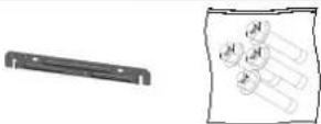 | |
| Vent Screens (3" [7.6 cm]) 2 Screens |  | |
| Isolation Valve* On some models only |  | 1 |
| Pressure Relief Valve for DHW (ASME Certified) (3/4",150 psi)* On some models only |  | 1 |
| Emergency Kit |  | 1 |
Table 3 – Items Included with the Water Heater
SAFETY REGULATIONS
• A. OPERATION AND INSTALLATION WARNINGS
To avoid serious injury or death, read, understand, and follow all the precautions listed here.
! DANGER
| DANGER |
| Vapors from flammable liquids will explode and can cause a fire, resulting in personal injury or death. The water heater has a burner that can come on at any time and ignite vapors. DO NOT use or store flammable liquids around the water heater. |
| Improper venting can cause a build-up of carbon monoxide. Breathing carbon monoxide can result in brain damage or death. DO NOT operate the water heater unless it is properly vented to the outside and has an adequate fresh air supply for safe operation. Inspect the exterior exhaust gas outlet port and fresh air inlet port on a regular basis to ensure they are functioning properly. |
| A concentration of carbon monoxide as small as .04% (400 parts per million) in the air can be fatal. When making high fire or low fire adjustments, CO levels must be monitored using a flue gas analyzer such that a CO level of no more than 150 ppm is exceeded at any time during operation. |
| Adjusting the “low fire offset” or the “main flow restrictor” in small increments can result in a significant increase in CO concentration. To avoid serious injury or death, DO NOT make any adjustments to the gas valve without monitoring the exhaust gases with a fully functional and calibrated flue gas analyzer. |
WARNING
| WARNING |
| This water heater must be installed by a licensed plumber, licensed gas fitter, and/or professional service technician. Improper installation and/or operation can cause a potentially hazardous situation, which, if not avoided, could result in serious injury or death, and will void the warranty. |
| Rheem cannot anticipate every circumstance that might involve a potential hazard. Each installation has its own specialized characteristics, requirements, and possible hazards. Therefore, all possible incidents are not included in these warnings. Proper and safe installation, operation, and service are the responsibility of the professional service technician. |
| Proper care of the water heater is the user's responsibility. Ensure the user carefully reads and understands the User's Information Manual before operating and maintaining the water heater. |
| Make sure the user knows the location of the gas shut-off valve and how to operate it. Immediately close the gas shut-off valve if the water heater is subjected to fire, overheating, flood, physical damage, or any other damaging condition that might affect the operation of the unit. Have the water heater checked by a qualified technician before resuming operation.Do not power up the unit unless the gas and water supply valves are fully opened. Make sure the fresh air intake port and exhaust gas port are open and functional. |
| No one but a professional service technician should attempt to install, service, or repair this water heater. There are no serviceable parts which can be changed by the user / owner. User / Owner: Contact the original professional service technician if the water heater needs repair or maintenance. If the original technician is unavailable, ask your gas supplier for a list of qualified service providers. |
WARNING
| Keep the area around the water heater clean and free of all materials that can burn. DO NOT store or place gasoline, oils, spray paint, or other flammable products near the water heater. |
| DO NOT use spray paint, hair spray, or any other flammable spray near the water heater or near the exterior fresh air intake port. DO NOT place any items in or around the exterior exhaust gas outlet port and/or fresh air inlet port that could restrict or block the flow in or out of the vent system. |
| DO NOT store or place newspapers, laundry, or other combustible items near the water heater or the exterior exhaust gas outlet and/or fresh air inlet port. |
| The owner should inspect the system monthly for damage, water stains, signs of rust, corrosion, and exhaust vent and air intake blockage. If inspection of the unit shows signs of damage, the water heater should be shut off until the problem is repaired by a qualified technician. |
| After installation, all water heater safety devices should be tested. |
| This water heater is certified for indoor installations only. The water heater consists of gas ignition system components which must be protected from water (dripping, spraying, etc.) during operation and service. Carefully consider installation location and the placement of critical components (circulators, condensate neutralizers, etc.) before installing the water heater. |
| DO NOT allow children to operate this unit. DO NOT use this unit if it does not appear to be operating correctly. A qualified technician should service and inspect the water heater annually. |
| The water heater temperature is factory set to 120 °F (49°C). To avoid scalding, always check the temperature of the hot water before bathing, showering, washing, etc. DO NOT adjust the water temperature while the water heater is being used by other persons. |
NOTICE
| If the water heater is exposed to the following, do not operate until all corrective steps have been made by a qualified service technician:1. FIRE2. DAMAGE3. WATER |
| DO NOT alter or modify the water heater or water heater controls. This can be dangerous and WILL VOID the warranty. |
| This water heater is equipped with a three prong plug. It should only be plugged directly into a properly grounded three prong receptacle. DO NOT remove the ground plug from the plug. |
| Any claims for damage or shortage in shipment must be filed immediately against the transportation company by the consignee. |
| This water heater provides a overheat shutdown limit. In the event the water heater water exceeds the set point of the control limit, the cutoff will trip and the water heater will shut down. Certain local codes require additional temperature limits. In addition, certain types of systems may operate at temperatures below the minimum set point of the limit provided with the water heater. Contact Rheem for additional overheat controls. |
NOTE: When inquiring about service or troubleshooting, reference the model and serial numbers from the water heater rating label.
WARNING
| DO NOT USE THIS APPLIANCE IF ANY PART HAS BEEN SUBMERGED IN WATER. Immediately call a qualified service technician. The appliance MUST BE replaced if it has been submerged. Attempting to operate an appliance that has been submerged could create numerous harmful conditions, such as a potential gas leakage causing a fire and/or explosion, or the release of mold, bacteria, or other harmful particulates into the air. Operating a previously submerged appliance could result in property damage, severe personal injury, or death.NOTE: Appliance damage due to flood or submersion is considered an Act of God, and IS NOT covered under product warranty. |
| Be sure to disconnect electrical power before opening water heater cabinet or performing service. Label all wires while performing service to ensure proper re-wiring of the water heater. Wiring errors can cause improper or dangerous operation. Failure to do so could result in an electrical shock, improper water heater operation, property damage, serious personal injury, or death. |
• B. IMPROPER COMBUSTION
WARNING
| Do not obstruct the flow of combustion and ventilating air. Adequate air must be provided for safe operation. Failure to keep the exhaust vent and intake pipe clear of ice, snow, or other debris could result in property damage, serious personal injury, or death. |
C. GAS
Should overheating or gas supply fail to shut off, do not turn off or disconnect electrical supply to the circulator. Instead, shut off the gas supply at a location external to the appliance
• D. WHEN SERVICING THE WATER HEATER
- To avoid electric shock, disconnect electrical supply before performing maintenance.
- To avoid severe burns, allow water heater to cool.
- Do not use petroleum-based cleaning or sealing compounds in a water heater system. Gaskets and seals in the system may be damaged, possibly resulting in substantial property damage.
- Do not use "homemade cures" or "patent medicines". Substantial property damage, damage to water heater, and/or serious personal injury may result.
• Always verify proper operation after servicing the water heater.
• E. WATER CHEMISTRY REQUIREMENTS
IMPORTANT
Chemical imbalance of the water supply may affect efficiency and cause severe damage to the appliance and associated equipment. Water quality must be professionally analyzed to determine whether it is necessary to treat the water. Various solutions are available to adjust water quality. Adverse water quality will affect the reliability of the system. In addition, operating temperatures above 135 °F will accelerate the build-up of lime scale and possibly shorten appliance service life. Failure of an appliance due to lime scale build-up, low pH, or other chemical imbalance IS NOT covered by the warranty.
The water must be potable, free of corrosive chemicals, sand, dirt, and other contaminates. It is up to the installer to ensure the water does not contain corrosive chemicals or elements that can damage the heat exchanger. Potable water is defined as drinkable water supplied from utility or well water in compliance with EPA secondary maximum contaminant levels (40 CFR Part 143.3) as shown in the table below. If the water contains contaminants higher than outlined by the EPA, water treatment is recommended and additional, more frequent maintenance may be required.
If you suspect that your water is contaminated in any way, discontinue use of the appliance and contact an authorized technician or licensed professional.
| Contaminant | Maximum Allowable Level | Contaminant | Maximum Allowable Level |
| Total Hardness(Residential Use - Below 140°F water temperature) | 200 mg/l(12 grains/gallon) pH 6.5-8.5 | ||
| Total Hardness(Commercial Use - 140°F and above water temperature) | 120 mg/l Sulfate 205 mg/l | ||
| Aluminum 0.05 to 0.2 mg/l | Total Dissolved Solids (TDS) 500 mg/l | ||
| Chloride 100 mg/l Zinc 5 mg/l | |||
| Manganese 0.05 mg/l D | ssolved Carbon Dioxide (CO) | 2) | 15 mg/l or PPM |
Table 4 – Water Quality Specifications
• F. FREEZE PROTECTION
IMPORTANT
Consider water heater piping and installation when determining water heater location.
NOTE: Damages resulting from incorrect installation or from use of products not approved by Rheem ARE NOT covered by warranty.
The water heater control is equipped with freeze protection that activates based on internal water temperature. See the table below for details on freeze protection operation.
NOTE: Freeze protection will not be active if the water heater loses power.
| System Freeze Protection(Activates Based on Internal Water Temperature) | Freeze Protection Operation |
| Stage 1 – If control detects water temperature of 46 °F (8°C) and below, the internal pump cycles until the control detects return water temperature of 50°F (10°C) and above. | |
| Stage 2 – If control detects water temperature of 41 °F (5°C) and below, the burner and internal pump will run continuously until the control detects return water temperature of 104°F (40°C) and above. |
Table 5 – Freeze Protection Detail
! DANGER
Households with small children, disabled, or elderly persons may require 120 °F (49°C) or lower thermostat setting to prevent contact with "HOT" water
| APPROXIMATE TIME / TEMPERATURE RELATIONSHIPS IN SCALDS | |
| 120°F More than 5 minutes | |
| 125°F 1 1⁄2 to 2 minutes | |
| 130°F About 30 seconds | |
| 135°F About 10 seconds | |
| 140°F Less than 5 seconds | |
| 145°F Less than 3 seconds | |
| 150°F About 1 1⁄2 seconds | |
| 155°F About 1 second | |
Table 6 – Time and Temperature Relationship in Scalds
This heater can deliver scalding water. Be careful whenever using hot water to avoid scalding injury. Certain appliances, such as dishwashers and automatic clothes washers may require increased water temperature. By setting the thermostat on this heater to obtain the increased water temperature required by these appliances, you may create the potential for scald injury.
To protect against injury, you should install a mixing valve in the water system. This valve will reduce point of discharge temperature by mixing cold and hot water in branch supply lines. Such valves are available from your local plumbing supplier.
Table 6 details the relationship of water temperature and time with regard to scald injury and may be used as a guide in determining the safest water temperature for your applications.

• H. HIGH ELEVATION INSTALLATIONS
! DANGER
Natural gas at high elevation might contain less heating value than typical 1,000 BTU/cu ft and therefore can cause improper air / gas mix leading to improper combustion. For natural gas installations above 3,000 ft, call your gas provider to determine the heating value of the supplied natural gas.water
To set the water heater to operate at the installation elevation, see INSTALLER MODE, this manual.
• A. SPECIFICATIONS
| Model Name | RTGH-RH11DV RTGH-RH10DV | |||||
| Gas Input Rate | MAX 199,000 Btu/h 180,000 Btu/h | |||||
| MIN 18,000 Btu/h 18,000 Btu/h | ||||||
| High Altitude(2,500~4,500ft) | 180,000 Btu/h 180,000 Btu/h | |||||
| Hot Water Capacity | 35°F Rise 11.0 Gal 9.9 Gal | |||||
| 45°F Rise 8.5 Gal 7.7 Gal | ||||||
| 77°F Rise 5.0 Gal 4.5 Gal | ||||||
| Installation Indoor Wall Hung | ||||||
| Flue System Sealed Combustion Direct Vent, Single Vent | ||||||
| Max Vent Run 2"(50ft) / 3"(100ft) Schedule 40 PVC, CPVC, PP | ||||||
| Orifice Size | NG (Gas / Needle) 0.342"(8.7mm) / 0.354"(9.0mm) | |||||
| LP (Gas / Needle) 0.263"(6.7mm) / 0.267"(6.8mm) | ||||||
| Gas Supply Pressure | NG 5.0" W.C to 10.5" W.C | |||||
| LP | 9.5" W.C to 13.0" W.C | |||||
| Manifold Pressure | Gas Type | NG | LP | NG | LP | |
| Low Fire | 2" VENT | -0.07" W.C | -0.02" W.C | -0.07" W.C | -0.02" W.C | |
| 3" VENT | -0.07" W.C | -0.02" W.C | -0.07" W.C | -0.02" W.C | ||
| High Fire | 2" VENT | -0.38" W.C | -0.3" W.C | -0.36" W.C | -0.28" W.C | |
| 3" VENT | -0.33" W.C | -0.25" W.C | -0.31" W.C | -0.23" W.C | ||
| Power Supply | Main Supply | 120V 60Hz | ||||
| Maximum Power Consumption | 172W(82W+90W_PUMP) | |||||
| Ignition System | Direct Electronic Ignition / Automatic Flame Sensing | |||||
| Burner System | Premixed Metal Fiber Burner | |||||
| Gas Valve System | Air ratio valve | |||||
| Minimum Flow Activation Flow | 0.5 GPM | |||||
| Internal Pipe Material | STS 304, Copper Tubing | |||||
| Dimensions | W17.3" - H28.7" - D14.8" | |||||
| Weight | 85 lbs | |||||
| Water Holding Capacity | Under 2 Gallon | |||||
| Control Panel / Main Controller | P-950C / NGTH-9700C | |||||
| Water Pressure | MAX | Hot water 150 psi | ||||
| MIN | 15 psi | |||||
| Materials | Casing | Cold Rolled Carbon Steel | ||||
| Heat Exchanger | Heat Exchanger : STS 304 | |||||
| Safety Devices | Flame Sensor, Overheat Cut Off Limit Switch ,Gas Leak Detector sensor, Water Leak Detector SensorExhaust Temperature Sensor,Water Temperature Sensor | |||||

| NO | Name of Component |
| 1 | Exhaust Outlet Collar |
| 2 | Ignition Trans |
| 3 | Ignition Rod |
| 4 | Over-heating Switch |
| 5 | Primary Heat Exchanger |
| 6 | H/E Temperature Sensor |
| 7 | Secondary Heat Exchanger |
| 8 | Control Panel |
| 9 | Mixing Valve |
| 10 | Recirculation Pump |
| 11 | 'DHW' supply Adapter |
| 12 | Condensate Trap |
| 13 | Low level sensor |
| 14 | Recirculation Return Adapter |
| NO | Name of Component |
| 15 | Main Controller |
| 16 | ‘DHW’ Inlet Filter |
| 17 | ‘DHW’ Inlet Adapter |
| 18 | Gas Inlet Adapter |
| 19 | Manual Power Switch |
| 20 | Water Flow Control Valve |
| 21 | Air Pressure Switch |
| 22 | Flame Detection Sensor |
| 23 | Gas Valve |
| 24 | Burner Case |
| 25 | AGM(Air Gas Mixer) |
| 26 | BLDC Fan |
| 27 | Air Intake Filter |
| 28 | Air Intake Collar |
C. DIMENSIONS
![4.0" [101mm] 11.5" [292mm] 4.6" [117mm] A B 14.8" [376 mm]](/content/2026/05/910178/images/7ecf4a4a4427c861a00b8576c27b979466c544a9174cbec7b276c51242caab26.jpg)
![6.1" [156mm] 5.4" [136mm] 2.4" [60mm] D E C G 2.6" [67mm] 3.2" [81mm] 6.8" [173mm] 10.2" [260mm] 13.6" [346mm]](/content/2026/05/910178/images/32893c1d5d2d781d607d064efd679f9caae789d5af3b8472da3db159e6331ef5.jpg)
![17.3" [439 mm] 28.7" [728mm]](/content/2026/05/910178/images/976285bcd5a99478b84dd1e94f87aecd3a7f37efa04ba92bca58454ff1aa7cae.jpg)
Figure 2 – Specifications and Dimensions
| DESCRIPTION DIAMETER | ||
| A Exhaust Outlet Pipe 3" (7.6 cm) | ||
| B Air Intake 3" (7.6 cm) | ||
| C DHW Outlet Adapter 34" (1.9 cm) | ||
| D Condensate Adapter 12" (1.2 cm) | ||
| E Recirculation Return 34" (1.9 cm) | ||
| F DHW Inlet Adapter 34" (1.9 cm) | ||
| G Gas Inlet 34" (1.9 cm) |
Table 7 – Adapter Specifications
flowchart
graph TD
    A["Hot water drain"] --> B["Condensate drain"]
    B --> C["Cold Water drain"]
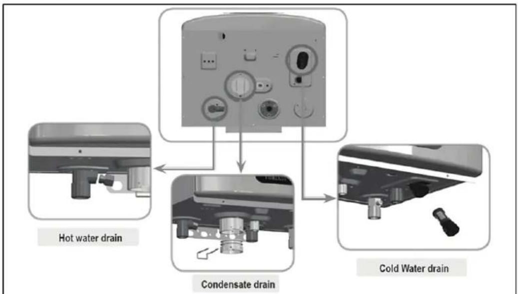
Figure 3 – Water Heater Drainage Locations
PREPARE WATER HEATER LOCATION
IMPORTANT
Carefully consider installation when determining water heater location. Please read the entire manual before attempting installation. Failure to properly take factors such as water heater venting, piping, condensate removal, and wiring into account before installation could result in wasted time, money, and possible property damage and personal injury.
• A. BEFORE LOCATING THE WATER HEATER
WARNING
Incorrect ambient conditions can lead to damage to the heating system and put safe operation at risk. Ensure that the water heater installation location adheres to the information included in this manual. Failure to do so could result in property damage, serious personal injury, or death.
IMPORTANT
Failure of water heater or components due to incorrect operating conditions IS NOT covered by product warranty.
-
Installation Area (Mechanical Room) Operating Conditions
-
Ensure ambient temperatures are higher than 33ircF / 0.6ircC and lower than 120ircF / 49ircC
- Prevent the air from becoming contaminated by the products, places, and conditions listed in this manual.
- Avoid continuously high levels of humidity
- Never close existing ventilation openings
IMPORTANT
The service life of the water heater's exposed metallic surfaces, such as the cabinet, as well as internal surfaces, such as the heat exchanger, are directly influenced by proximity to damp and salty marine environments. In such areas, higher concentration levels of chlorides from sea spray coupled with relative humidity can lead to degradation of the heat exchanger and other water heater components. In these environments, water heaters must not be installed using direct vent systems which draw outdoor air for combustion. Such water heaters must be installed using room air for combustion. Indoor air will have a much lower relative humidity and, hence, potential corrosion will be minimized.
WARNING
This water heater is certified for indoor installations only. Do not install the water heater outdoors. Failure to install this water heater indoors could result in substantial property damage, severe personal injury, or death.
This water heater must be installed as described in this manual: upright, with the vent adapters in the vertical position. DO NOT attempt to install this water heater in any other orientation. Doing so will result in improper water heater operation and property damage, and could result in serious personal injury or death.
- Check for nearby connections to:
- System water piping
- Venting connections
- Gas supply piping
- Electrical power
- Condensate drain
IMPORTANT
Locate the water heater where any leakage from the relief valve, related piping, tank, or connections will not result in damage to surrounding areas or lower floors of the building. The water heater should be located near a floor drain, or installed in proximity to an adequately drained drain pan. Rheem WILL NOT be held liable for leakage damages.
To conserve water and energy, insulate all water piping, especially the hot and recirculation water lines.
- Check area around water heater. Remove any combustible materials, gasoline, and other flammable liquids.
WARNING
Failure to keep water heater area clear and free of combustible materials, liquids, and vapors can result in substantial property damage, severe personal injury, or death.
-
Gas control system components must be protected from dripping water during operation and service.
-
If the water heater is to replace an existing water heater, check for and correct any existing system problems, such as:
-
System leaks
- Location that could cause the system and water heater to freeze and leak.
- Incorrectly-sized expansion tank
IMPORTANT
| Do not connect the water heater to any heating systems or components that have been previously used for non-potable applications. |
| Do not introduce toxic chemicals, such as antifreeze or water heater treatments, into the water heater or any piping meant for potable water purposes. |
| Ensure that all piping and components connected to the water heater are suitable for potable water applications. |
| Do not use this water heater for space heating applications. |
| Circulators suitable for DHW applications must be used. |
| The service life of the water heater's exposed metallic surfaces, such as the cabinet, as well as internal surfaces, such as the heat exchanger, are directly influenced by proximity to damp and salty marine environments. In such areas, higher concentration levels of chlorides from sea spray coupled with relative humidity can lead to degradation of the heat exchanger and other water heater components. In these environments, water heaters must not be installed using direct vent systems which draw outdoor air for combustion. Such water heaters must be installed using room air for combustion. Indoor air will have a much lower relative humidity and, hence, potential corrosion will be minimized. |
- Clean and flush system when reinstalling a water heater.
NOTE: When installing in a zero clearance location, it may not be possible to read or view some product labeling. It is recommended to make note of the water heater model and serial number.
B. LEVELING
IMPORTANT
| In order for the condensate to properly flow out of the collection system, the water heater must be installed level. |
• C. CLEARANCES FOR SERVICE ACCESS
See Table 8 for recommended service clearances. If these minimum clearances are not provided, it may not be possible to service the water heater without removing it from the space.
WARNING
| Space must be provided with combustion/ventilation air openings correctly sized for all other appliances located in the same space as the water heater. The water heater cover must be securely fastened to prevent it from drawing air from the water heater room. This is particularly important if the water heater is in a room with other appliances. Failure to comply with the above could result in substantial property damage, severe personal injury, or death. |
| MINIMUM CLEARANCES | ||
| Installation Clearances from Non-Combustibles / Combustibles Recommended Service and Proper Operation Clearances | ||
| Top 9 in. (228.6 mm) | 9 in. (228.6 mm) | |
| Back 5/8 in. (15.9 mm) | 5/8 in. (15.9 mm) | |
| Front 6 in. (152.4 mm) | 24 in. (609.6 mm) or more (Front of Water heater)(A combustible door or removable panel is acceptable front clearance.) | |
| Right Side | 3 in. (76.2 mm) 3 in. (76.2 mm) | |
| Left Side | ||
| Bottom 12 in. (304.8 mm) | 12 in. (304.8 mm) | |
Table 8 – Minimum Installation and Service Clearances
NOTE: The exhaust vent piping for this direct vented appliance is approved for zero clearance to combustible construction.
NOTE: If the water heater is installed in a narrow space or corner, ensure that there is sufficient space for service and maintenance access. There should be easy access to the gas and water lines and internal components for future service. A combustible door or removable panel is acceptable front clearance.
• D. RESIDENTIAL GARAGE AND CLOSET INSTALLATIONS
IMPORTANT
| Check with your local Authority Having Jurisdiction for requirements when installing water heater in a garage or closet. Please read the entire manual before attempting installation. Failure to properly take factors such as venting, piping, condensate removal, and wiring into account before installation could result in wasted time, money, and possible property damage and personal injury. |
PRECAUTIONS
If the water heater is located in a residential garage, it should be installed per the latest edition of the National Fuel Gas Code, ANSI Z223.1, and CGA-B149 Installation Code in Canada.
- Mount the bottom of the water heater a minimum of 18" (457 mm) above the floor of the garage, to ensure the burner and ignition devices are well off the floor.
- Locate or protect the water heater so it cannot be damaged by a moving vehicle.
WARNING
The space must be provided with correctly sized combustion/ventilation air openings for all other appliances located in the space with the water heater. Do not install the water heater in an attic. Failure to comply with these warnings could result in substantial property damage, severe personal injury, or death.
• E. EXHAUST VENT AND INTAKE PIPE
WARNING
Vents must be properly supported. The water heater exhaust and intake connections are not designed to carry heavy weight. Vent support brackets must be within 1' (30 cm) of the water heater and the balance at 4' (1.22 m) intervals. Venting must be readily accessible for visual inspection for the first 3' (91 cm) from the water heater.
NOTE: To prevent combustion air contamination, see Table 9 in this section when considering exhaust vent and intake pipe termination.
Exhaust vent and intake pipe may be vented vertically through the roof or out a side wall. Venting methods are detailed in the Venting Section. Do not attempt installation using any other means. Be sure to locate the water heater so exhaust vent and intake piping can be routed through the building and properly terminated. Exhaust vent and intake piping lengths, routing, and termination method must comply with methods and limits given in the venting section.
• F. CARBON MONOXIDE DETECTORS
In the Commonwealth of Massachusetts and As Required by State and Local Codes
Installation of Carbon Monoxide Detectors: At the time of installation or replacement of the vented gas fueled appliance, the installing plumber or gas fitter shall observe that a hard wired carbon monoxide detector with an alarm and battery back-up is installed on the floor level where the gas appliance is installed, unless the appliance is located in a detached, uninhabitable structure separate from the dwelling, building, or structure used in whole or in part for residential purposes.
In addition, the installing plumber or gas fitter shall observe that a hard wired carbon monoxide detector with an alarm and battery back-up is installed on each additional level of the dwelling, building, or structure served by the vented gas appliance. It shall be the responsibility of the property owner to secure the service of qualified licensed professionals for the installation of hard wired carbon monoxide detectors.
a. In the event that the vented gas fueled appliance is installed in a crawl space or attic, the hard wired carbon monoxide detector with alarm and battery back-up shall be installed on the next adjacent floor level.
b. In the event that these requirements cannot be met at the time of completion of installation, the owner shall have a period of thirty (30) days to comply with the above requirements; provided, however, that during said thirty (30) day period, a battery operated carbon monoxide detector with an alarm shall be installed.
WARNING
Failure to comply with these requirements could result in product damage, severe personal injury, or death.
Approved Carbon Monoxide Detectors: Each carbon monoxide detector as required in accordance with the above provisions shall comply with NFPA 70 and be ANSI/UL 2034 listed and IAS certified.
• G. PREVENT COMBUSTION AIR CONTAMINATION
Install intake piping for the water heater as described in the Venting section. Do not terminate exhaust in locations that can allow contamination of intake air.
WARNING
Ensure that the intake air will not contain any of the contaminants below. For example, do not pipe intake near a swimming pool. Avoid areas subject to exhaust fumes from laundry facilities. These areas always contain contaminants. Contaminated air will damage the water heater, resulting in possible substantial property damage, severe personal injury, or death.
| PRODUCTS TO AVOID AREAS LIKELY TO HAVE CONTAMINANTS | |
| Spray cans containing fluorocarbons Dry cleaning/laundry areas and establishments | |
| Permanent wave solutions Swimming pools | |
| Chlorinated waxes/cleaners Metal fabrication plants | |
| Chlorine-based swimming pool chemicals Beauty shops | |
| Calcium chloride used for thawing Refrigeration repair shops | |
| Sodium chloride used for water softening Photo processing plants | |
| Refrigerant leaks Auto body shops | |
| Paint or varnish removers Plastic manufacturing plants | |
| Hydrochloric or Muriatic acid Furniture refinishing areas and establishments | |
| Cements and glues New building construction | |
| Antistatic fabric softeners used in clothes dryers Remodeling areas | |
| Chlorine-type bleaches, laundry detergents, and cleaning solvents | Garages and workshops |
| Adhesives used to fasten building products | |
Table 9
NOTE: DAMAGE TO THE WATER HEATER CAUSED BY EXPOSURE TO CORROSIVE VAPORS IS NOT COVERED BY WARRANTY. (Refer to the limited warranty for complete terms and conditions).
• H. REMOVING A WATER HEATER FROM A COMMON VENT SYSTEM
! DANGER
Do not install the water heater into a common vent with any other appliance. This will cause flue gas spillage or appliance malfunction, resulting in possible substantial property damage, severe personal injury, or death.
! DANGER
Failure to follow all instructions can result in flue gas spillage and carbon monoxide emissions, causing severe personal injury or death.
When removing an existing water heater, the following steps must be followed.
- Seal any unused openings in the common venting system.
- Visually inspect the venting system for proper size and horizontal pitch to determine if there is blockage, leakage, corrosion or other deficiencies that could cause an unsafe condition.
-
If practical, close all building doors, windows and all doors between the common venting system and other spaces in the building. Turn on clothes dryers and any appliances not connected to the common venting system. Turn on any exhaust fans, such as range hoods and bathroom exhausts, at maximum speed. Do not operate a summer exhaust fan. Close all fireplace dampers.
-
Place in operation the appliance being inspected. Follow the lighting instructions.
Adjust the thermostat so the appliance will operate continuously.
-
Test for spillage at the draft hood relief opening after 5 minutes of main burner operation. Use the flame of a match or candle or smoke from a cigarette.
-
After it has been determined that each appliance remaining connected to common venting system properly vents when tested as outlined, return doors, windows, exhaust fans, fireplace dampers and any other gas burning appliance to their previous condition of use.
-
Any improper operation of the common venting system should be corrected so the installation conforms to the National Fuel Gas Code, ANSI Z223.1. When resizing any portion of the common venting system, the common venting system should be resized to approach the minimum size as determined using the appropriate tables in Appendix G in the National Fuel Gas Code, ANSI Z 223.1.
WARNING
Breathing Hazard - Carbon Monoxide Gas
natural_image
Silhouette of a person emitting particles from a bottle (no text or symbols)- Do not operate heater if flood damaged.
• Install vent system in accordance with local codes and manufacturers installation instructions. - Do not obstruct heater air intake or exhaust. Support all vent piping per manufacturers installation instructions.
- Do not place chemical vapor emitting products near unit.
- According to NFPA 720, carbon monoxide detectors should be installed outside each sleeping area.
- Never operate the heater unless it is vented to the outdoors.
- Analyze the entire vent system to make sure that condensate will not become trapped in a section of vent pipe and therefore reduce the open cross sectional area of the vent.
Breathing carbon monoxide can cause brain damage or death. Always read and understand instruction manual.
- I. UNPACKING THE WATER HEATER
WARNING
UNPACKING WATER HEATER – Any claims for damage or shortage in shipment must be filed immediately against the transportation company by the consignee.
IMPORTANT
Cold weather handling – If water heater has been stored in a very cold location (below 0irc F) before installation, handle with care until the plastic components come to room temperature.
Remove all sides of the shipping crate to allow the water heater to be lifted into its installation location.
• J. WALL-MOUNTING THE WATER HEATER
WARNING
The water heater must be installed on a wall that can bear its weight (more than 88 lbs. [40 kg] when fully plumbed and full of water). Installing the water heater on a wall which cannot support its weight could result in property damage, personal injury, or death.
The water heater may be installed on any suitable internal wall (suitable sound-proofing may be required when installing onto a stud partition wall).
WARNING
This water heater is too heavy for one person to lift. It is highly recommended to install the water heater with two people. Use caution as to not drop the water heater, which could damage the water heater and cause property damage and/or severe personal injury. Verify that the water heater is properly and securely mounted before leaving unsupervised. Failure to comply with the above and properly mount the water heater could result in substantial property damage, severe personal injury, or death.
This wall mounting system is not seismic rated and should not be applied as such. Failure to comply with the above and properly mount the water heater could result in substantial property damage, severe personal injury, or death.
POSITIONING THE WATER HEATER ON THE WALL
- Attach the wall bracket on the location where you want to install the water heater. Ensure it is level and on stud (16" [406 mm] centers) before proceeding.
- Mark the two (2) drill holes with a pencil or marker. Remove the wall bracket.
- Drill two (2) holes using a 15/32" (12mm) drill bit at the marked hole locations.
- Mount the wall bracket to the wall with the two (2) included anchor bolts. Ensure the mounted bracket is level. Place washers and nuts on each anchor bolt and tighten. See Figure 4.
- Align the heater bracket grooves on the back of the water heater with the tongues on the wall bracket and hang the water heater on the bracket. See Figure 4.

natural_image
3D CAD renderings of a mechanical assembly with bracket, housing, and mounting bracket (no text or symbols)Figure 4 – Wall Mounting the Water Heater Top BracketHeater
- Locate the lower mounting bracket on the bottom of the water heater. The two (2) screws and dry wall anchors will be used to secure the bottom of the unit to the wall.
- Mark two (2) holes. Remove the water heater from the wall.
- Drill two (2) holes with a 17/64" (7mm) size bit. Then insert two (2) dry wall anchors into the wall.
- Place the water heater back on the wall as described in Step 5.
- Screw the two (2) screws into the dry wall anchors.

natural_image
Mechanical assembly diagram showing a component being processed into a housing (no text or symbols visible)
Figure 5 – Wall Mounting the Water Heater
VENTING
! DANGER
Vent this water heater in accordance with these instructions. Failure to do so will result in property damage, severe personal injury, or death.
WARNING
DO NOT mix vent systems or materials unless specifically told to do so in this manual.
DO NOT thermally insulate the exhaust vent or intake pipes.
DO NOT use an electric damper, vent damper, or draft hood with this water heater.
DO NOT locate the exhaust vent or intake pipe terminations where exposed to prevailing winds.
Moisture will be produced by the exhaust vent. Take precautions when determining exhaust vent termination. Moisture may fall from the vent termination to the ground and turn to ice in freezing conditions. Moisture or ice can produce a hazardous condition.
Exhaust condensate is acidic, and could deteriorate the surface below the exhaust vent termination. Ensure this surface is in good repair (sealed, painted, etc.) to prevent deterioration.
Failure to follow these instructions could result in property damage, severe personal injury, or death.
• A. INTAKE PIPE AND EXHAUST VENT GUIDELINES
- Vent system must be installed in accordance with local codes, or, in absence of local codes, the National Fuel Gas Code, ANSI Z223.1 / NFPA 54 and/or CSA B149.1, Natural Gas and Propane Installation Code.
- For installation in Canada, installer supplied plastic vent piping must comply with CAN/CGA B149.1 and be certified to the Standard for Type BH Gas Venting Systems, ULC-S636. Components of this listed system must not be interchanged with other vent systems or unlisted pipes or fittings. All plastic components and specified primers and glues must be from a single system manufacturer and must not be intermixed with another system manufacturer's products. Clean and dry all applicable surfaces before applying cement.
- This water heater is designed to be installed in as a direct vent (sealed combustion) type. In direct vent installations, combustion air must be supplied directly from the outdoors to the burner, and the flue (exhaust) gases should be vented directly to the outdoors through the wall or roof.
- This water heater uses 2" (5.1 cm) or 3" (7.6 cm) diameter pipe for exhaust vent and
intake pipe. It is important to ensure an airtight seal from the water heater collar to the vent terminations. It is EXTREMELY IMPORTANT that the maximum allowed combined venting lengths are not exceeded. See Table 11 for a list of Approved Vent Materials and Table 12 for Approved Vent Lengths.
-
Do not install venting system components on the exterior of the building except as specifically required by these instructions.
-
Vent terminals must be at least 1 foot (30 cm) from any door, window, or gravity inlet into the building.
- Maintain the correct clearance and orientation between the exhaust vent and intake pipe terminals.
• The exhaust vent and air intake terminals must be at the same height and their center lines must be spaced apart 1 foot (30 cm) minimum. - The bottom of the exhaust vent and intake pipe terminals must be at least 1 foot (30 cm) above the normal snow accumulation level. In no case should these terminals be installed less than 1 foot (30 cm) above normal snow accumulation level.
- Do not install the exhaust vent terminals directly above windows or doors.
- Intake pipe terminal must not terminate in areas that might contain combustion air contaminates, such as near swimming pools.
- For sidewall venting, the minimum horizontal distance between adjacent exhaust vent terminations is 1 foot (30 cm). It is recommended this distance be greater than 1 foot (30 cm) to better avoid frost damage to building surfaces.
- For roof venting, minimum horizontal distance between any adjacent exhaust vent termination is 1 foot (30 cm).
- If the exhaust vent is to be terminated in a walled off area (such as a roof with a parapet wall), ensure the exhaust vent terminates a minimum of 10' (3m) from nearest wall and extends level with or above the top of the wall. This will ensure flue gas does not get trapped and possibly recirculated into the intake air pipe, which could contaminate the combustion air.
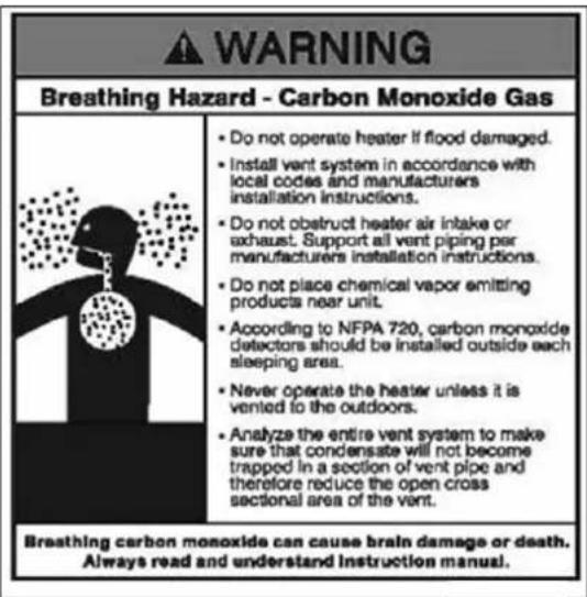
WARNING
All joints of positive pressure vent systems must be sealed completely to prevent leakage of flue products into living space.
- Remove all burrs and debris from joints and fittings.
- When using PVC or CPVC pipe, all joints must be properly cleaned, primed, and cemented. Use only cement and primer approved for use with the pipe material. Cement must conform to ASTM D2564 for PVC and ASTM F493 for CPVC pipe.
NOTE: DO NOT CEMENT POLYPROPYLENE PIPE.
- Ensure the vent is located where it will not be exposed to prevailing winds.
- In all roof venting applications, exhaust discharge must point away from the pitch of the roof.
- To prevent water leakage, install adequate roof flashing where the pipe enters the roof.
- Do not locate vent over public walkways, driveways, or parking lots. Condensate could drip and freeze, resulting in a slip hazard or damage to vehicles and machinery.
- Due to potential moisture build-up, sidewall venting may not be the preferred venting option. To save time and cost, carefully consider venting installation and location.
- Horizontal lengths of exhaust vent must slope back towards the water heater not less than 14'' (0.6 cm) per foot to allow condensate to drain from the vent pipe.
- The exhaust vent must terminate where vapors cannot make accidental contact with people or pets, or damage shrubs or plants.
• In vacant chimney applications, install and seal a rain cap over existing chimney openings.
- All piping must be fully supported. Use pipe hangers at a minimum of 4 foot (1.22 m) intervals to prevent sagging of the pipe where condensate may form.
- Do not use the water heater to support any piping.
- DO NOT vent near soffit vents, crawl space vents, or other areas where condensate or vapor could create a nuisance or hazard or cause property damage.
- DO NOT vent where condensate vapor could cause damage or could be detrimental to the operation of regulators, relief valve, or other equipment.
- DO NOT vent the water heater in a chimney flue serving a separate appliance designed to burn solid fuel. The water heater may only be vented in vacant chimneys.
- Maximum Snow Level Determination: These installation instructions reference snow levels in establishing a minimum height for the installation of exhaust vent or air intake terminations. Snow levels shall be determined as follows:
a. The installation location may, by ordinance, designate how snow levels are calculated in that location; or
b. In the absence of specific ordinances, snow levels shall be calculated from the average monthly maximum depth of snow accumulation as indicated by the National Weather Service's 10 year statistics for the installation location/geographical area.
In the Commonwealth of Massachusetts and as Required by State and Local Codes:
- The vented gas fueled appliance shall not be installed so its combustion, ventilation, or dilution air is obtained from a bedroom or bathroom.
- Signage: Whenever any through-the-wall (horizontal or sidewall) vent is installed less than seven feet above the finished grade, a metal or plastic identification plate shall be permanently mounted to the exterior of the building at a minimum height of eight feet above grade directly in line with the exhaust vent terminal. The sign shall read, in print no less than 0.5 inches in size, "GAS VENT DIRECTLY BELOW. KEEP CLEAR OF ALL OBSTRUCTIONS".
- Marking of Exhaust Vent and Intake Pipe: Piping used for ventilation, make-up, or combustion air intake shall be labeled as follows:
a. Throughout the entire developed length:
i. Labels must be placed every ten feet for exposed/visible piping; or
ii.Labels must be placed every three feet for concealed piping.
b. At all changes of direction;
c. On each side of a penetration through a partition, wall or ceiling; and
d. The labels shall be black lettering that:
i. Indicates that the piping is used for ventilation, make-up, or combustion air intake, and
ii. The letters shall be sized equal to a minimum of the pipe diameter. However, for piping with a diameter exceeding two inches, said lettering does not need to be larger than two inches.

Figure 6 - Vent Termination Detail
| Description US Canadian | ||||
| A Clearance above grade, veranda, porch, deck, or balcony 1 foot (30 cm) 1 foot (30 cm) | ||||
| B Clearance to window or door that may be opened | Direct Vent 1 | foot (30 cm) | 3 feet (91 cm) | |
| Power Vent | 1 foot (30 cm) above, or 4 feet (1.22 m) below or to side of opening | |||
| C Clearance to permanently closed window * * | ||||
| D | Vertical clearance to ventilated soffit located above the terminal within a horizontal distance of 2 feet from the center line of the terminal | * | * | |
| E Clearance to unventilated soffit * * | ||||
| F Clearance to outside corner * * | ||||
| G Clearance to inside corner * * | ||||
| H | Clearance to each side of center line extended above meter/regulator assembly | * | 3 feet (91 cm) with a height 15 feet (4.57 m) above meter / regulator assembly | |
| I | Clearance to service regulator vent outlet | * | 3 feet (91 cm) | |
| J | Clearance to non-mechanical air supply inlet to building or the combustion air inlet to any other appliance | Direct Vent | 12 in (30 cm) | 3 feet (91 cm) |
| Power Vent | 1 foot (30 cm) above, or 4 feet (1.22 m) below or to side of opening | |||
| K | Clearance to a mechanical air supply inlet | 3 ft (91 cm) above if within 10 ft (3 m) horizontally | 6 feet (1.83 m) | |
| L | Clearance above paved sidewalk or paved driveway located on public property | * | 1 foot (30 cm) | |
| M | Clearance under veranda, porch, deck, or balcony | * | 12 in (30 cm) ‡ | |
Table 10 – Vent Termination Clearances - *NOTE: For clearances not specified in ANSI Z223.1/NFPA 54 or CAN/CSA-B 149.1, please use clearances in accordance with local installation codes and the requirements of the gas supplier.
• B. APPROVED VENT MATERIALS
WARNING
Consult Table 11 or the most recent edition of ANSI Z223.1/NFPA 54 or CAN/CGA B149.1 as well as all applicable local codes and regulations when selecting vent pipe materials.
| APPROVED EXHAUST VENT AND INTAKE PIPE MATERIAL | |||
| Item Material | Standards for Installation in: | ||
| United States Canada | |||
| Exhaust vent or Intake pipe and fittings | CPVC schedule 40 ASTM-D | 2846 PP, CPVC, and PVC venting must be ULC-S636 Certified. IPEX is an approved manufacturer in Canada, supplying vent material listed to ULC-S636. | |
| PVC schedule 40 ANSI/ASTM D1785 | |||
| Polypropylene ULC-S636 | UL-1738 | ||
| Stainless Steel AL29-4C | Certified for Category IV and direct vent appliance venting | Certified for Category IV and direct vent appliance venting | |
| Pipe Cement | PVC ANSI/ASTM D2 | 564 | IPEX System 636 Cements & Primers |
| CPVC ANSI/ASTM F4 | 93 | ||
| Pipe Primer PVC / CPVC ASTM F656 | |||
Table 11 – Approved Venting Materials
! DANGER
- The exhaust and intake components installed with this water heater must be used for near water heater piping BEFORE transitioning to the approved materials listed above. DO NOT REMOVE these installed components. Doing so WILL VOID warranty.
- PVC/CPVC pipe and fittings of the same diameter are considered interchangeable.
- Use of cellular core pipe PVC (ASTM F891), cellular core CPVC, or Radel® (polyphenysulfone) in nonmetallic venting systems is prohibited.
- DO NOT connect PVC/CPVC to PP without an approved vent connector.
- When installing AL29-4C vent piping, install a PVC-to-stainless adapter at the water heater vent connection, and at the termination when using a Rheem PVC termination kit. DO NOT mix AL29-4C piping from different manufacturers unless using adapters specifically designed for the purpose by the manufacturer.
- Covering non-metallic vent pipe and fittings with thermal insulation is prohibited.
- DO NOT obstruct the flow of combustion or ventilation air.
- When using Pipe Cement/Primer, follow the instructions included with the Cement/Primer closely. Clean and dry all applicable surfaces before applying.
Failure to follow these directions will result in substantial property damage, severe personal injury, or death.
IMPORTANT
High heat sources (sources generating heat 100 °F / 37 °C or greater, such as stove pipes, space heaters, etc.) may damage plastic components of the water heater as well as plastic vent pipe materials. Such damages ARE NOT covered by warranty. It is recommended to keep a minimum clearance of 8" from high heat sources. Observe heat source manufacturer instructions, as well as local, state, provincial, and national codes, laws, regulations and ordinances when installing this water heater and related components near high heat sources.
WARNING
Vent adaptors are not designed as load-bearing devices, and must not be used to support exhaust vent piping. All vent pipes must be properly connected, supported, and the exhaust must be pitched a minimum of 14 " per foot back to the heater to allow drainage of condensate. Failure to properly support vent piping and follow the information in this statement could result in product damage, severe personal injury, or death.
• C. Allowed Schedule 40 Vent Length (PVC, CPVC, PP)
1. Maximum Vent Length (Intake/outlet)
| Number of 90° elbows | Maximum length of 2" straight pipe | Maximum length of 3" straight pipe |
| 0 or 1 50ft.(15.24m) 100ft. (30m) | ||
| 2 42ft. (12.8m) 95ft. (29m) | ||
| 3 34ft. (10.4m) 90ft. (27.4m) | ||
| 4 26ft. (7.9m) 85ft. (25.9m) | ||
| 5 18ft. (5.4m) 80ft. (24.4m) | ||
| 6 Not Available 75ft (22.9m) |
A. 3 inch diameter 90irc elbow is equivalent to 5ft. (1.5m) of straight pipe.
A. 2 inch diameter 90irc elbow is equivalent to 8ft. (2.4m) of straight pipe.
A. 3 inch diameter 45irc elbow is equivalent to 2.5ft. (0.75m) of straight pipe.
A. 2 inch diameter 45irc elbow is equivalent to 4ft. (1.2m) of straight pipe.
2. Minimum Vent Length (Intake/outlet)
| Number of 90° elbows | Minimum length of 2" straight pipe | Minimum length of 3" straight pipe |
| 1 7ft. (2.1m) 7ft. (2.1m) |
• D. TIGHTENING WATER HEATER COLLAR TO EXHAUST VENT AND INTAKE PIPE
This appliance uses 2" (5.1 cm) or 3" (7.6 cm) diameter pipe for exhaust vent and intake pipe. In order to use 2" (5.1 cm) pipe, it is required to reduce pipe size in a vertical length of pipe with a 3" (7.6 cm) x 2" (5.1 cm) reducing coupling (not included). Follow the steps below to install 3" (7.6 cm) pipe into the appliance collar. See Figure 7 for additional details.
- Clean and dry the appliance connection. DO NOT use primer or cement on the appliance connection.
- Push the length of pipe into the connection until it touches the bottom of the fitting.
- Tighten the clamps using a screwdriver.
- Ensure the pipe is secure before continuing installation.
- For 2" (5.1 cm) installations, install the reducing coupling in a vertical section of pipe. At least a 6" (15.2 cm) length of 3" (7.6 cm) pipe MUST BE INSTALLED before reducing to 2" (5.1 cm). See Figure 8

natural_image
Two technical diagrams showing mechanical components mounted on a base, one with a cylindrical component and the other with a cylindrical component (no text or symbols present)Figure 7 – Correct Installation into the Water Heater Collar

Figure 8 – Transitioning from 3" (7.6 cm) to 2" (5.1 cm) Vent Pipe
WARNING
Do not use bushing to reduce vent size. Doing so could result in product damage, severe personal injury, or death.
• E. VENT TERMINATION
- Direct Vent, Two Pipe Roof and Sidewall Vent Terminations Check Primary and Gas Piping


Figure 9 – Direct Vent, Roof and Sidewall Vent Terminations
WARNING
All vent pipes must be glued, properly supported, and the exhaust must be pitched a minimum of 14 " (0.6 cm) per foot back to the appliance to allow drainage of condensate. When placing support brackets on vent piping, the first bracket must be within 1 foot (30 cm) of the appliance and the balance at 4 foot (1.22 m) intervals on the vent pipe. Appliance venting must be readily accessible for visual inspection for the first three feet from the appliance.
- Direct Vent, Optional Horizontal and Vertical Vent Kits


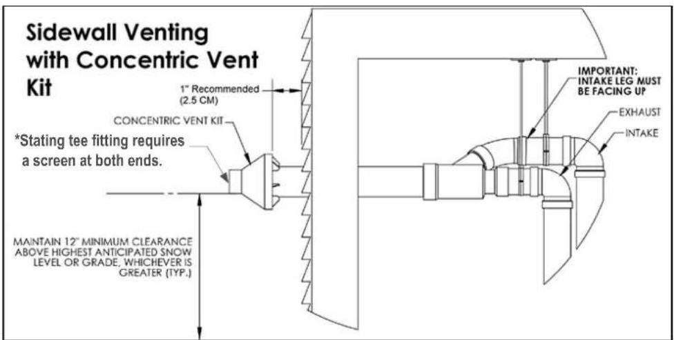
Figure 10 – Direct Vent, Vent Terminations (With Optional Kits)
WARNING
All vent pipes must be glued, properly supported, and the exhaust must be pitched a minimum of 14 " (0.6 cm) per foot back to the appliance to allow drainage of condensate. When placing support brackets on vent piping, the first bracket must be within 1 foot (30 cm) of the appliance and the balance at 4 foot (1.22 m) intervals on the vent pipe. Appliance venting must be readily accessible for visual inspection for the first three feet from the appliance.
3. Screen Installation
After connecting the intake air and exhaust vent pipes, it is required to install the included screens into the exhaust vent and intake pipe terminations to prevent damages to the unit due to blockages. See Figure 11 for installation detail.
Screens can freeze in areas with severe cold weather. In such areas it is recommended not to use screens.

Figure 11 - Screen Installation - NOTE: Vent termination elbow is meant to be installed open end facing the ground. Orientation in Figure 11 is meant to demonstrate proper Vent Screen installation ONLY.
FOR YOUR SAFETY
Do not connect any other appliance vents to the water heater exhaust vent or intake pipes.
4. Power Venting, Indoor Combustion Air Installation in Confined or Unconfined Space
NOTE: This water heater should be installed using direct venting in any instance where there are or may be flammable vapors in the area.
FOR YOUR SAFETY
Do not store or use gasoline or other flammable vapors and liquids in the vicinity of this or any other appliance. To do so may result in an explosion or fire.
This appliance requires fresh, uncontaminated air for safe operation and must be installed in a mechanical room where there is adequate combustion and ventilating air. NOTE: To prevent combustion air contamination, see Table 9. Follow the National Fuel Gas Code (ANSI Z223.1 / NFPA 54).
Combustion air from the indoor space can be used if the space has adequate area or when air is provided through a duct or louver to supply sufficient combustion air based on the appliance input. Never obstruct the supply of combustion air to the appliance. If the appliance is installed in areas where indoor air is contaminated (see Figure 12) it is imperative that the appliance be installed as direct vent so that all combustion air is taken directly from the outdoors into the appliance intake connection.
Unconfined space is space with volume greater than 50 cubic feet per 1,000 Btu/hour (4.8 cubic meters per kW) of the total input rating of all fuel-burning appliances installed in that space. Rooms connected directly to this space, through openings not furnished with doors, are considered part of the space.
Confined space is space with volume less than 50 cubic feet per 1,000 Btu/hour (4.8 cubic meters per kW) of the total input rating of all fuel-burning appliances installed in that space. Rooms connected directly to this space, through openings not furnished with doors, are considered part of the space.
When drawing combustion air from inside a conventionally constructed building to a confined space, such space should be provided with two permanent openings: one located 6" (15 cm) below the space ceiling, the other 6" (15cm) above the space floor. Each opening should have a free area of one square inch per 1,000 Btu/hr (22cm 2 /kW) of the total input of all appliances in the space, but not less than 100 square inches (645).
If the confined space is within a building of tight construction, air for combustion must be obtained from the outdoors as outlined in the Venting section of this manual. See Figure 13.


Figure 12 - LP-325-X
INDOOR COMBUSTION AIR (SINGLE PIPE) _HORIZIONTAL

INDOOR COMBUSTION AIR (SINGLE PIPE)_Vertical

Figure 13 – NOTE: These drawings are meant to demonstrate system venting only. The installer is responsible for all equipment and detailing required by local codes.
! DANGER
Common Vented water heaters must be direct vented, with an exhaust vent and intake air pipe vented to the outdoors. DO NOT power vent Common Vented water heaters! Doing so will result in property damage, severe personal injury, or death.
These water heaters can be common vented. Connecting several water heaters together requires proper sizing of the intake and exhaust pipes. Up to eighteen water heaters can be connected (cascading) together.
1. VENT DIAMETER SIZING AND LENGTHS
These water heaters are designed for 3 inch exhaust vent and intake pipes. The following chart outlines the maximum length of common venting allowable. A vent system's length is calculated by adding the length of all straight pieces used (both horizontal and vertical) and then adding the equivalent lengths of each fitting used in the system. A vent system's length must not exceed the maximum length outlined in the chart below.

| Maximum Vent Length (in Ft.) for Direct Vent (2 Pipe) | |||||||
| Number of Water Heaters Common Vented | Load (BTU/Hr) | Pipe Size | |||||
| 3" | 4" | 6" | 8" | 10" | 12" | ||
| 1 199,000 100 N/A | N/A N/A N/A N/A | ||||||
| 2 398,000 50 83 | |||||||
Table 13 – Maximum Common Vent Length for Direct Vent (2 Pipe)
NOTE: Reduce the maximum equivalent length above by 5 feet per 90 °C elbow used and by 2 feet per 45 °C elbow used. DO NOT exceed the above set limits.
2. RECOMMENDED EXHAUST PIPE TRANSITIONS

Do not use a 90 degree t-fitting for the exhaust.

natural_image
Simple line drawing of a gun with two ribbons and a prohibition symbol (no text or labels)Do not use 90 degree transition into a reducer or a straight pipe.

Do not direct exhaust from opposite directions. Use a 45 degree transition as shown.


natural_image
Simple line drawing of a bench with a circular symbol above it (no text or labels)Do not use reducers in a straight run of pipe.
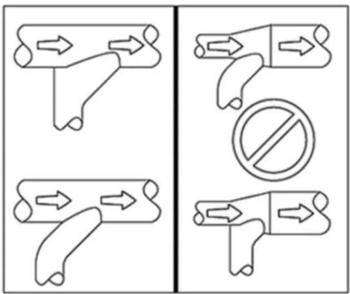
flowchart
graph TD
    A["Arrow"] --> B["Arrow"]
    C["Arrow"] --> D["Arrow"]
    E["Arrow"] --> F["Arrow"]
    G["Arrow"] --> H["Arrow"]
    I["Circle with diagonal no"] --> J["Arrow"]
Do not transition into a reducer or use a t-fitting. Transitions should always be directed into a straight run of pipe.
Figure 14 – Recommended Exhaust Pipe Transitions
3. TWO PIPE VENT SYSTEM (DIRECT VENT)
! DANGER
Common Vented water heaters must be direct vented with an exhaust vent and intake air pipe vented to the outdoors. DO NOT power vent Common Vented water heaters! Doing so will result in property damage, severe personal injury, or death.
The water heater can be direct vented without any modification using a 3 inch diameter pipe. The following diagrams represent some typical direct venting configurations and are included to assist in designing the vent system. Possible configurations are not limited to the following diagrams. See Table 13 for trunk line sizing when common venting multiple heaters.

Figure 15 – Common Vented Water Heaters – Unbalanced Venting
WARNING
All vent pipes must be glued, properly supported, and the exhaust must be pitched a minimum of 14 " per foot back to the appliance to allow drainage of condensate. When placing support brackets on vent piping, the first bracket must be within 1 foot of the appliance and the balance at 4 foot intervals on the vent pipe. Appliance venting must be readily accessible for visual inspection for the first three feet from the appliance.
NOTE: This drawing is meant only to demonstrate system venting. The installer is responsible for all equipment and detailing required by local codes. For sidewall applications, terminate the outlet on the exterior wall at least 12" above the ground, or as required by local building codes. In areas of high snowfall, protect both sidewall and roof vent terminations from blockage by installing at least 12" above the maximum anticipated snowfall accumulation.

Figure 16 –Common Vented Direct Vent Configurations
WARNING
All vent pipes must be glued, properly supported, and the exhaust must be pitched a minimum of 14 " per foot back to the appliance to allow drainage of condensate. When placing support brackets on vent piping, the first bracket must be within 1 foot of the appliance and the balance at 4 foot intervals on the vent pipe. Appliance venting must be readily accessible for visual inspection for the first three feet from the appliance.
NOTE: This drawing is meant only to demonstrate system venting. The installer is responsible for all equipment and detailing required by local codes. For sidewall applications, terminate the outlet on the exterior wall at least 12" above the ground, or as required by local building codes. In areas of high snowfall, protect both sidewall and roof vent terminations from blockage by installing at least 12" above the maximum anticipated snowfall accumulation.
! DANGER
Common Vented water heaters must be direct vented, with an exhaust vent and intake air pipe vented to the outdoors. DO NOT power vent Common Vented water heaters! Doing so will result in property damage, severe personal injury, or death.
NOTE: This drawing is meant only to demonstrate system venting. The installer is responsible for all equipment and detailing required by local codes. For sidewall applications, terminate the outlet on the exterior wall at least 12" above the ground, or as required by local building codes. In areas of high snowfall, protect both sidewall and roof vent terminations from blockage by installing at least 12" above the maximum anticipated snowfall accumulation.
Condensate piping to floor drain
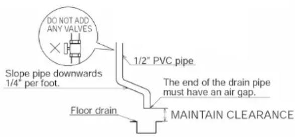
Condensate piping with pump

Figure 17 – Condensate Detail
GAS PIPING
WARNING
FIRE AND/OR EXPLOSION HAZARD
To avoid serious injury or death, the gas line installation and the gas line inlet pressure test must be done by a licensed professional.
Always match the water heater with the type of gas supplied to the unit (natural gas or LP gas). This water heater must be converted into propane operation unless specifically manufactured for use with propane. Follow Gas Conversion Manual instructions (separate document). Propane ready water heaters have the suffix "LP" after the model serial number.
Make sure the gas line pressures are within normal limits. Pressures outside normal limits can result in poor performance and hazardous operating conditions.
This water heater must be converted into propane operation unless it is specifically manufactured to operate on propane. Propane-ready water heaters have the suffix "LP" after the model serial number. Failure to ensure the water heater is set to operate on the provided gas supply could result in property damage, personal injury, or death.
• A. GAS PIPE SIZING TABLES
1. Gas Pipe Sizing
This information is for reference use only. Refer to gas pipe manufacturer specifications for actual delivery capacity. The DOE standard for Natural Gas is 1100 BTU/ft 3 . Contact the local gas supplier for actual BTU/ft 3 rating.
2. Natural Gas Pipe Sizing
The following tables list maximum capacity of pipe in cubic feet of gas per hour for gas pressures of 11" (27.9 cm) or less and a pressure drop of 0.5 inches (0.12 kPa) water column, based on a 0.60 specific gravity for natural gas.
| Maximum Natural Gas Delivery Capacity – Length of Corrugated Stainless Steel Pipe in Feet | ||||||||||
| Pipe size | Cubic Feet per Hour (0.60 Specific Gravity, 0.5 WC [0.12 kPa] Pressure Drop) | |||||||||
| 10 20 30 | 40 50 60 80 | 100 150 200 | ||||||||
| 12" (1.2 cm) 82 58 | 47 41 37 37 | 29 26 20 18 | ||||||||
| 34" (1.9 cm) 192 | 137 112 97 87 | 80 69 62 48 | 44 | |||||||
| 1" (2.5 cm) 383 | 269 218 188 | 168 153 132 | 18 91 82 | |||||||
| 1 14" (3.1 cm) 639 | 456 374 325 | 292 267 232 | 208 171 148 | |||||||
| 1 12" (3.8 cm) 126 | 0 888 723 625 | 559 509 440 | 393 320 277 | |||||||
| 2" (5 cm) 2930 | 2080 1700 147 | 70 1320 1200 | 1040 933 762 661 | |||||||
| Maximum Natural Gas Delivery Capacity – Length of Black Iron Pipe (Sch. 40 Metallic) in Feet | ||||||||||
| Pipe size | Cubic Feet per Hour (0.60 Specific Gravity, 0.5 WC [0.12 kPa] Pressure Drop) | |||||||||
| 10 20 30 | 40 50 60 80 | 100 150 200 | ||||||||
| 12" (1.2 cm) 10 20 | 30 40 50 60 | 80 100 150 | 200 | |||||||
| 34" (1.9 cm) 172 | 18 95 81 72 | 65 56 50 40 | 34 | |||||||
| 1" (2.5 cm) 360 2 | 47 199 170 | 151 137 117 | 104 83 71 | |||||||
| 1 14" (3.1 cm) 678 | 466 374 320 | 284 257 220 | 195 157 134 | |||||||
| 1 12" (3.8 cm) 1390 | 957 768 65 | 7 583 528 45 | 2 400 322 275 | |||||||
| 2" (5 cm) 2090 | 1430 1150 98 | 5 873 791 67 | 7 600 482 412 | |||||||
| 2 12" (6.35 cm) 402 | 2 2760 2220 | 1900 1680 | 1520 1300 1160 | 928 794 | ||||||
| 3" (7.6 cm) 6400 | 4400 3530 30 | 20 2680 243 | 20 2080 1840 | 1480 | 1270 | |||||
| 4" (10.1 cm) | 11300 | 7780 | 6250 | 5350 | 4740 | 4290 | 3670 | 3260 | 2610 | 2240 |
| 23100 | 15900 | 12700 | 10900 | 9660 | 8760 | 7490 | 6640 | 5330 | 4560 | |
Table 14 – Natural Gas Delivery Capacity – Corrugated Stainless Steel Pipe – Refer to ANSI Z223.1 – National Fuel Gas Code, Latest Edition
Table 15 – Natural Gas Delivery Capacity – Black Iron Pipe – Refer to ANSI Z223.1 – National Fuel Gas Code, Latest Edition
3. LP (Liquid Propane) Gas Pipe Sizing
The following is intended for use for piping between a Single or Second Stage (Low Pressure) Regulator and the water heater. The following tables list maximum capacity of pipe in cubic feet of gas per hour for an inlet pressure of 14" water column and specific pressure drop of 0.5 inches (0.12 kPa) water column based on 1.5 specific gravity for liquid propane.
| Maximum Liquid Propane Delivery Capacity – Length of Corrugated Stainless Steel Pipe in Feet | ||||||||||
| Pipe size | Cubic Feet per Hour (1.5 Specific Gravity, 0.5 WC [0.12 kPa] Pressure Drop) | |||||||||
| 10 20 30 40 50 60 80 100 150 200 | ||||||||||
| 12" (1.2 cm) 129 | 91 | 74 | 64 | 58 | 53 | 45 | 41 | 31 | 28 | |
| 34" (1.9 cm) 303 | 216 | 177 | 153 | 137 | 126 | 109 | 98 | 75 | 69 | |
| 1" (2.5 cm) 605 | 425 | 344 | 297 | 265 | 241 | 208 | 186 | 143 | 129 | |
| 1 14" (3.1 cm) 971 | 661 | 528 | 449 | 397 | 359 | 307 | 270 | 217 | 183 | |
| 1 12" (3.8 cm) 1990 | 1400 | 1140 | 988 | 884 | 805 | 696 | 621 | 506 | 438 | |
| 2" (5 cm) 4640 | 3290 | 2680 | 2330 | 2080 | 1900 | 1650 | 1480 | 1210 | 1050 | |
Table 16 – Liquid Propane Delivery Capacity – Corrugated Stainless Steel Pipe – Refer to ANSI Z223.1 – National Fuel Gas Code, Latest Edition
| Maximum Liquid Propane Delivery Capacity – Length of Black Iron Pipe (Sch. 40 Metallic) in Feet | ||||||||||
| Pipe size | Cubic Feet per Hour (1.5 Specific Gravity, 0.5 WC [0.12 kPa] Pressure Drop) | |||||||||
| 10 20 30 | 40 50 60 80 | 100 150 200 | ||||||||
| 12" (1.2 cm) | 291 | 200 | 160 | 137 | 122 | 110 | 101 | 94 | 84 | 67 |
| 34" (1.9 cm) 608 | 418 336 287 | 255 231 212 | 197 175 140 | |||||||
| 1" (2.5 cm) 1150 | 787 632 541 | 480 434 400 | 372 330 265 | |||||||
| 1 14" (3.1 cm) | 2350 | 1620 | 1300 | 1110 | 985 | 892 | 821 | 763 | 677 | 543 |
| 1 12" (3.8 cm) 3520 | 2420 1940 | 1660 1480 1340 | 1230 1140 | 1010 | 814 | |||||
| 2" (5 cm) 6790 | 4660 3750 3210 | 2840 2570 | 2370 2200 | 1950 | 1570 | |||||
Table 17 – Liquid Propane Delivery Capacity – Black Iron Pipe – Refer to ANSI Z223.1 – National Fuel Gas Code, Latest Edition
• B. GAS CONNECTION REQUIREMENTS
- The gas connection fitting on the water heater is 34 " (1.9 cm) female NPT. NOTE: The pipe size must not be less than 34 " (1.9 cm).
- The supply line must be sized for the maximum output of the water heater being installed. If there are additional gas appliances from the main supply line, measure the size of the supply line according to the COMBINED total maximum BTUH draw for the appliances as if they were operating at the same time.
- Measure the length of the gas supply line from the gas meter to the water heater. Water heater must be installed downstream of the gas meter to ensure adequate gas supply. Use the tables in this manual or refer to the gas line manufacturer's sizing information to determine the correct supply pipe size.
-
A manual gas shut-off valve should be installed in the gas supply line close to the water heater. See Figure 18 for detail.
-
To facilitate any future maintenance, it is also recommended that an approved gas union fitting be installed in the supply line between the shut-off valve and the 34 " (1.9 cm) female NPT connection on the water heater.
• B. GAS CONNECTION REQUIREMENTS
- The gas connection fitting on the water heater is 34" (1.9 cm) female NPT. NOTE: The pipe size must not be less than 34" (1.9 cm).
- The supply line must be sized for the maximum output of the water heater being installed. If there are additional gas appliances from the main supply line, measure the size of the supply line according to the COMBINED total maximum BTUH draw for the appliances as if they were operating at the same time.
- Measure the length of the gas supply line from the gas meter to the water heater. Water heater must be installed downstream of the gas meter to ensure adequate gas supply. Use the tables in this manual or refer to the gas line manufacturer's sizing information to determine the correct supply pipe size.
- A manual gas shut-off valve should be installed in the gas supply line close to the water heater. See Figure 18 for detail.
- To facilitate any future maintenance, it is also recommended that an approved gas union fitting be installed in the supply line between the shut-off valve and the 34 " (1.9 cm) female NPT connection on the water heater.

Figure 18 – Gas Line With Shut-Off Valve Detail
- Test the gas pressure to make sure it meets the minimum standards and does not exceed the maximum standards of the water heater.
- Leak test the gas line pipe before placing the water heater in operation. Only use approved leak detector liquid solutions to check for leaks.
- A properly sized gas regulator must be installed 18" away from the water heater.
- Do not operate the water heater until all connections have been completed and the heat exchanger is filled with water.

Figure 19 – Natural Gas Piping Installation – NOTE: Capacity to be not Less than Total Capacity of Connected Appliances

flowchart
graph TD
    A["LP GAS TANK"] --> B["1/2" pipe"]
    B --> C["Full size gas pipe"]
    C --> D["Gas Regulator (2 psi)"]
    D --> E["Gas Regulator (supply press 12")"]
    E --> F["Sediment Trap"]
    F --> G["Other appliance"]
    H["Manual shut off valve"] --> C
    I["Manual shut off valve"] --> D
Figure 20 – LP Gas Piping Installation – NOTE: Capacity to be Not Less than Total Capacity of Connected Appliances
• C. ADDITIONAL PRECAUTION FOR EXCESS FLOW VALVE (EFV)
If an excess flow valve (EFV) is in the gas line, check the manufacturer's minimum and maximum flow capacity ratings. An improperly sized EFV will not allow for a full flow of gas to the water heater and will cause the water heater to malfunction. See Figure 21.
• D. ADJUSTING GAS PRESSURE AT THE WATER HEATER
NOTE: Refer Figure 22 when adjusting gas pressure. Loosen the bolts before checking the gas inlet pressure.

Figure 21 – Excess Flow Valve (EFV)
1. The water heater and its individual shutoff valve must be disconnected from the gas supply piping system during any pressure testing of the system at test pressures greater than 12 psi (3.5 kPa).
2. The water heater must be isolated from the gas supply piping system by closing its individual manual shutoff valve during any pressure testing of the gas supply piping system at test pressures equal to or less than 12 psi (3.5 kPa). The minimum and maximum inlet gas line pressures must meet the requirements shown in Table 18.
| LP GAS / NATURAL GAS | |
| Minimum Pressure | 5.0" W.C (1.25 kPa) |
| Maximum Pressure | 13.0" W.C (3.24 kPa) |
Table 18 – Gas Pressure Requirements
| NOTICE |
| Do not fire (operate) the water heater until all connections have been completed and the heat exchanger is filled with water. Doing so will damage the water heater and void the warranty. |
• E. SETTING AND VERIFYING THE COMBUSTION SETTING
NOTE: Turn on a hot water faucet at a nearby location in the water heating system to draw water at a high flow rate. This will ensure the water heater will run continuously while running the combustion test.

Figure 22 – Inlet Gas Pressure Port Detail
NOTICE
Do not fire (operate) the water heater until all connections have been completed and the heat exchanger is filled with water. Doing so will damage the water heater and void the warranty.
- After the appliance has fired, flip DIP switch seven (7) to the ON position (low fire). Proceed to check appliance combustion values.
NOTE: Use a combustion analyzer to ensure CO and CO2 values are within the range shown in Table 19.

WARNING
It is required to use a combustion analyzer to verify final adjustment according to the combustion chart (Table 19). Failure to do so could result in serious personal injury or death.
If the readings obtained are lower or higher than the combustion readings in Table 19, use a 5m Allen key to adjust the offset screw in a clockwise (positive) or counterclockwise (negative) direction (approximately 1/4 turn). See Figure 23. Check your combustion values. Repeat this procedure until the values obtained on the combustion analyzer agree with those stated in Table 18.
NOTE: If the appliance makes a whistling sound (harmonics) at low fire, adjust the offset screw in a clockwise (positive) direction (approximately 1/8 turn). Check your combustion values and ensure they agree with those stated in Table 19 before proceeding.
WARNING
It is very important that this conversion be set within the recommended CO measurements listed in Table 19. Visually looking at the burner does not determine combustion quality. Failure to measure combustion with a Combustion Analyzer and set the throttle within the recommended CO measurements could result in property damage, severe personal injury, or death.
| COMBUSTION SETTINGS | ||||
| NATURAL GAS LP GAS | ||||
| FAN SPEED | LOW HIGH LOW HIGH | |||
| CO PPM <60 | <200 | <60 <200 | ||
| CO2 (%) 8 - | 10 8 1⁄2 - 10 1⁄2 9 - | 10 1⁄2 9 1⁄2 - 10 1⁄2 | ||
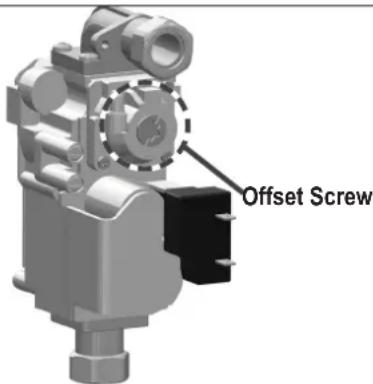
Table 19 – Combustion Settings
Figure 23 – Gas Valve Offset Screw
- When low fire settings have been obtained, flip DIP switch seven (7) to its original (OFF) position.
This will return the appliance to normal mode. - Flip DIP switch six (6) to ON (high fire). Again check combustion readings with a combustion analyzer.
- When complete, flip DIP switch six (6) to its original (OFF) position. This will return the appliance to normal mode.
Shut off water at hot water faucet.
- Allow appliance to operate normally. Ensure it is operating properly.
- Reinstall the appliance front cover.
WATER PIPING
A. GENERAL PLUMBING CONNECTION GUIDELINES
- Pipe material must be suitable to meet local codes and industry standards.
Do not use lead, PVC, iron, or any piping which has been treated with chromates, boiler seal, or other chemicals. - Pipe runs should be kept as short as possible to keep heat loss at a minimum.
- The pipe must be cleaned and without blemish before any connections are made.
- Do not apply a torch within 12" (30 cm) of the bottom connections of the water heater. Doing so could damage the water heater. Such damages ARE NOT covered by product warranty.
- The size of the hot water pipe should be 34'' (1.9 cm) diameter.
- Isolation (shutoff valves) are included and should be used to ease future servicing.
- All piping should be insulated.
- Ensure water pressure to the unit is within 14 (96 kPa) to 70 psi (483 kPa). If water pressure is too low or high, the water heater will not be able to perform to its full capacity and could be damaged. Such damages are not covered by product warranty.
- If the unit is installed on an upper level to supply water to the levels below, ensure the water pressure to the unit does not fall below 29 psi (200 kPa). It may be necessary to install a pump system to ensure that the water pressure is maintained at this level.
- If feed water pressure is too high take measures to prevent water hammer (such as installing a pressure regulating valve).
- If this water heater will be installed in an application where the supply water is hard, the water must be treated with a water softener. Water softeners may be regulated by the local codes. Consult with the Authority Having Jurisdiction for codes, sizing, and installation guidelines.

flowchart
graph TD
    A["Exhaust About 120°F (49°C)"] --> B["Air & Gas Mixing"]
    B --> C["Burner"]
    C --> D["Primary heat exchanger"]
    D --> E["Combustion gas about 400°F (200°C)"]
    E --> F["Secondary heat exchanger"]
    F --> G["Water is heated using the exhaust gas which is about 400°F (200°C)."]
    G --> H["Hot Water"]
    G --> I["Condensate"]
    G --> J["Cold Water"]
    G --> K["Gas"]
    style A fill:#f9f,stroke:#333
    style K fill:#f9f,stroke:#333
Figure 24.1 - Standard(DHW) Mode
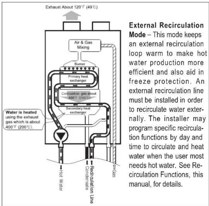
Figure 24.2 – External Recirculation Mode

flowchart
graph TD
    A["Exhaust About 120°F (49°C)"] --> B["Air & Gas Mixing"]
    B --> C["Burner"]
    C --> D["Primary heat exchanger"]
    D --> E["Combustion gas about 400°F (200°C)"]
    E --> F["Secondary heat exchanger"]
    F --> G["Recirculation Line"]
    G --> H["Condensate"]
    G --> I["Gas"]
    J["Water is heated using the exhaust gas which is about 400°F (200°C)."] --> G
Figure 24.3 – Preheat or Inernal Recirculation Mode
Internal Recirculation Mode allows the installer to program specific recirculation functions by day and time to circulate and heat water more efficiently - when the user most needs hot water. See Recirculation Functions, this manual, for details.
| Mode Description | Return Line | Installer Mode Setting | Hot Water Speed (To Fixtures) | Energy Usage | Default Recirculation Run Time | |
| Recirculation Setting (6:RC) | Recirculation Mode (7:RM) | |||||
| Standard (Default) | Same as Standard Tankless Water Heater | N/A OFF | N/A Good Best - | |||
| Internal Recirculation | Similar to Tank Water Heater without Recirculation Loop | N/A ON | Internal Better Better | 5:00 ~ 8:00 AM5:00 ~ 11:00 PM | ||
| External Recirculation | Quicker Hot Water with External Recirculation Loop | Required ON | External Best Good | |||
Table 20 – Detail of Recirculation Modes
* Cross-over kit is available for installations where dedicated return lines are not available.
B. INSTALL A BACKFLOW PREVENTER
It may be recommended to use a back flow preventer – check local codes. If a back flow preventer or a no return valve is used, a thermal expansion tank must be installed on the cold water supply between the water heater and valve.
WARNING
To control thermal expansion, a thermal expansion tank should be installed in systems with an installed backflow preventer. DO NOT use a closed type expansion tank. Follow expansion tank manufacturer's specifications to properly size an expansion tank to the installation. Failure to properly accommodate thermal expansion could result in property damage, severe personal injury, or death.
C. PIPING THE WATER HEATER
CAUTION
Use at least the MINIMUM pipe size for all water heater loop piping This is to avoid the possibility of inadequate flow through the water heater. Using less than the required minimum pipe size and piping could result in system problems, property damage, and premature water heater failure. Such problems ARE NOT covered by product warranty.
Use both thread tape and pipe dope to connect to the 34 " (1.9 cm) domestic water inlet and outlet. Tankless isolation valves between the city water supply and tank inlet are recommended for ease of service.
D. APPLICATIONS

Standard Mode
- Only POTABLE water may be plumbed through the water heater.
- The water heater cannot be used for space heating applications.
- Expansion tank is required if a backflow preventer is installed.
- Isolation valve kits are recommended for this installation.
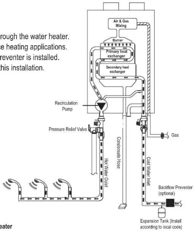
flowchart
graph TD
    A["Air & Gas Mixing"] --> B["Burner"]
    B --> C["Primary heat exchanger"]
    B --> D["Secondary heat exchanger"]
    C --> E["Recirculation Pump"]
    D --> F["Pressure Relief Valve"]
    E --> G["Hot Water Outlet"]
    F --> G
    G --> H["Condensate Hose"]
    H --> I["Gas"]
    I --> J["Cold Water Inlet"]
    J --> K["Backflow Preventer (optional)"]
    K --> L["Expansion Tank (Install according to local code)"]
Figure 25 – Standard Mode Piping, Single Water Heater
External Recirculation mode
The recirculation pipe must be installed in the field in order to use 'External Recirculation Mode'. This mode allows the water heater to recirculate heated water through the system and additionally serves as a freeze protection function.
When using external recirculation mode with the built-in pump, check the following maximum recirculation pipe lengths including fittings (3/4" pipe is recommended):
-1/2" Pipe- 200' (60m) of equivalent length -3/4" Pipe- 500' (150m) of equivalent length Lengths in excess of these limits will require an external recirculation pump.

flowchart
graph TD
    A["Afriger & Gas Mixing"] --> B["Burner"]
    B --> C["Primary heat exchanger"]
    B --> D["Secondary heat exchanger"]
    C --> E["Recirculation Pump"]
    D --> E
    E --> F["Pressure Relief Valve"]
    F --> G["Hot Water Outlet"]
    G --> H["Condenser Hosee"]
    H --> I["Gas"]
    I --> J["Cold Water Inlet"]
    J --> K["Expansion Tank (Install according to local code)"]
    L["Field in"] --> A
    M["Teally"] --> A
    N["s"] --> L
Figure 26 – Piping with External Recirculation Mode
NOTE: These drawings are meant to show system piping concept only. Installer is responsible for all equipment and detailing required by local codes.
Preheat or Internal Recirculation Mode
Preheat or Internal Recirculation Mode may be used without an installed recirculation pipe. The water heater is preheated and protected from freezing.

flowchart
graph TD
    A["Air & Gas Mixing"] --> B["Burner"]
    B --> C["Primary heat exchanger"]
    C --> D["Secondary heat exchanger"]
    D --> E["Recirculation Line"]
    E --> F["Recirculation Pump"]
    F --> G["Pressure Relief Valve"]
    G --> H["Hot Water Outlet"]
    H --> I["Condensate Hose"]
    I --> J["Gas"]
    J --> K["Cold Water Inlet"]
    K --> L["Expansion Tank (Install according to local code)"]
    style A fill:#f9f,stroke:#333
    style L fill:#ccf,stroke:#333
Figure 27 – Preheat or Internal Recirculation Mode
bYPS Recirculation Mode with Cross Over Valve

flowchart
graph TD
    A["Recirculation Line"] --> B["Burner"]
    B --> C["Air & Gas Mixing"]
    C --> D["Primary/heat exchanger"]
    D --> E["Secondary heat exchanger"]
    E --> F["Recirculation Line"]
    F --> G["Gas"]
    F --> H["Cold Water Inlet"]
    F --> I["Explosion Tank (Instal (Install according to local code))"]
    F --> J["Hot Water Outlet"]
    F --> K["Pressure Relief Valve"]
    F --> L["Recirculation Pump"]
    style A fill:#f9f,stroke:#333
    style B fill:#ccf,stroke:#333
    style C fill:#cfc,stroke:#333
    style D fill:#fcc,stroke:#333
    style E fill:#cff,stroke:#333
    style F fill:#ffc,stroke:#333
    style G fill:#fcc,stroke:#333
    style H fill:#fcc,stroke:#333
    style I fill:#fcc,stroke:#333
    style J fill:#fcc,stroke:#333
    style K fill:#fcc,stroke:#333
    style L fill:#fcc,stroke:#333
bYPS Recirculation Mode may be used with a cross over valve assembled at the furthest fitting
Figure 28 – Other Piping Configuration
NOTE: These drawings are meant to show system piping concept only. Installer is responsible for all equipment and detailing required by local codes.
180 / 199Kbtuh Pressure Drop
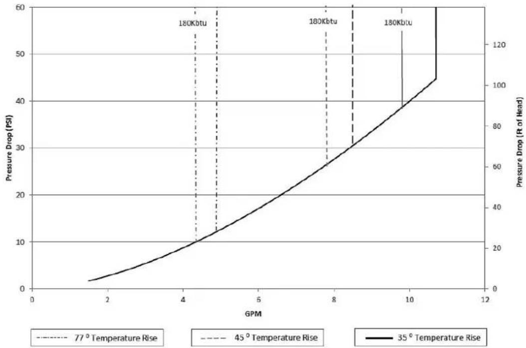
line
| GPM | Pressure Drop (PSI) | Pressure Drop (Rt of Head) | | --- | --- | --- | | 2 | ~2 | ~0 | | 4 | ~10 | ~20 | | 8 | ~30 | ~60 | | 10 | ~45 | ~100 | | 11 | ~60 | ~120 |Figure 29 – Pressure Drop through the Heat Exchanger
| RECOMMENDED WATER PIPE SIZE | |||||||||
| Number of units | ΔT = 77ircF (25ircC) ΔT = 45 | ircF (7.2ircC) ΔT = 35 | ircF (1.6ircC) | ||||||
| Flow Rate (GPM) | Water Velocity (ft/s) | Pipe Dia. (in) | Flow Rate (GPM) | Flow Rate (GPM) | Pipe Dia. (in) | Flow Rate (GPM) | Water Velocity (ft/s) | Pipe Dia. (in) | |
| 1 5 3.75 | 3/4 9 3.61 | 1 11 4.64 1 | |||||||
| 2 10 4.22 | 1 18 3.21 | 1 1/2 23 4.13 | 1 1/2 | ||||||
Table 21 – Recommended Water Pipe Size NOTE: The above pipe sizes are recommended based on maximum water velocity of 5 ft/s and maximum water temperature of 140irc F.
• E. PRESSURE RELIEF VALVE
An external pressure relief valve must be installed on this water heater. When installing, observe the following guidelines. Failure to comply with these guidelines can result in substantial property damage, personal injury, or death.
This water heater must be provided with an approved 150 psi (1,034 kPa), 3/4 ASME HV Valve that must be installed on the DHW outlet line (See Figure 30). The 150 psi Pressure Relief Valve must be installed on the DHW supply line to ensure a compliant installation and safe operation.
This water heater has a high-temperature shut-off switch built in as a standard safety feature. Therefore, a "pressure only" relief valve is required. DO NOT operate this water heater before the supplied pressure relief valve is installed with sufficient relieving capacity in accordance with the ASME rating plate on the water heater.

Figure 30 – Pressure Relief Valve
Pressure relief valves must be installed as close to the water heater as possible. No other valves should be placed between the pressure relief valve and the appliance. DO NOT install a relief valve with a pressure rating greater than 150 psi (1,034 kPa). This is the maximum allowable relief valve setting for this water heater.
After installing the relief valve and filling and pressurizing the system, test the operation of the valve by lifting the lever. Make sure the valve discharges freely. If the valve fails to operate correctly, replace it with a new relief valve. Ensure that the maximum BTU/H rating on the pressure relief valve is equal to or greater than the maximum input BTU/H rating of the water heater.
WARNING
To avoid water damage or scalding due to relief valve operation:
- Discharge line must be connected to relief valve outlet and run to a safe place of disposal. Terminate the discharge line in a manner that will prevent possibility of severe burns or property damage should the relief valve discharge.
- Discharge line must be as short as possible and the same size as the valve discharge connection throughout its entire length.
- Discharge line must pitch downward from the valve and terminate at least 6" (30 cm) above the floor drain, making discharge clearly visible.
- Discharge line shall terminate plain, not threaded, with a material serviceable for temperatures of 375ircF (191°C) or greater.
- Do not pipe discharge to any location where freezing could occur.
- No shutoff valve may be installed between the relief valve and water heater or in the discharge line. Do not plug or place any obstruction in the discharge line.
- Test the operation of the relief valve after filling and pressurizing the system by lifting the lever. Make sure the valve discharges freely. If the valve fails to operate correctly, replace it with a new relief valve.
- Test relief valve at least once annually to ensure the waterway is clear. If valve does not operate, turn the water heater "off" and call a plumber immediately.
• Take care whenever operating relief valve to avoid scalding injury or property damage. - For water heaters installed with only a pressure relief valve, the separate storage vessel must have a temperature and pressure relief valve installed. This relief valve shall comply with Relief Valves for Hot Water Supply Systems, ANSI Z21.22 CSA4.4.
FAILURE TO COMPLY WITH THE ABOVE GUIDELINES COULD RESULT IN FAILURE OF RELIEF VALVE OPERATION, RESULTING IN POSSIBILITY OF SUBSTANTIAL PROPERTY DAMAGE, SEVERE PERSONAL INJURY, OR DEATH.
CONNECT ELECTRICAL POWER / INITIAL STARTUP
WARNING
Install wiring and electrically ground water heater in accordance with the authority having jurisdiction or, in the absence of such an authority, follow the National Electrical Code, NFPA 70, and/or CSA C22.1 Electrical Code-Part 1 in Canada. Failure to follow all applicable local, state, and national regulations, mandates, and building supply codes for guidelines to install the electrical power supply could result in property damage, serious personal injury, or death.
WARNING
ELECTRICAL SHOCK HAZARD – To ensure safety, turn off electrical power supply at service entrance panel before making any electrical connections to avoid possible electric shock hazard. Failure to do so could result in property damage, serious personal injury, or death.
A. WIRING INFORMATION
- The electrical supply required by the water heater is 120V at 60Hz. Power consumption may be up to 172W. Use an appropriate, dedicated circuit.
- Do not disconnect the power supply when the water heater is not in use. When the power is off, the freeze protection in the water heater will not activate, resulting in possible freeze damage.
- Do not let the power cord contact gas piping. Tie redundant power cord outside the water heater. Putting the redundant length of cord inside the water heater may cause electrical interference and faulty operation.
- This water heater must be properly grounded. Ensure the electrical receptacle that the water heater will be plugged into is properly grounded.
- Do not attach the ground wire to either the gas or water piping, or to a telephone line.
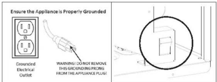
Figure 31 – Proper Grounding – Internal Manual Power Switch
- The wiring diagrams contained in this manual are to be used for reference purposes only.
- Refer to these diagrams and the wiring diagrams of any external controls used with the installation when wiring the water heater. Read, understand, and follow all wiring instructions supplied with the controls.
- Do not disconnect the power supply when the water heater is in normal operation.
NOTE: For additional electrical protection, the use of a whole house surge protector is recommended. Damage caused by power surges is not covered by the warranty.
NOTICE
If the water heater display does not come ON, first check the plug. Also check the electrical panel circuit breaker and reset it if necessary. If the circuit breaker trips again, do not reset. Disconnect the plug and have a qualified technician diagnose the problem.
B. DIP SWITCHES
There is one DIP switch block. DIP switches 6 and 7 need to be set to OFF for the water heater to operate normally. Factory Settings shown below.

199K NG

199K LP

180K NG

180K LP
DIP SWITCH GROUP
| DIP SWITCH OFF ON | |||
| 1 – 3 Factory Use Only Factory Use Only | |||
| 4 Factory Use Only Factory Use Only | |||
| 5 Gas Type LP NG | |||
| 6 High Fire Normal High Fire | |||
| 7 Low Fire Normal Low Fire | |||
Table 22 – DIP Switch Group
SYSTEM CONTROL SETTINGS
| MAXIMUM FLAME DETECTING VOLTAGE | 2.5V |
| PRE-PURGE TIME (Tp) | Maximum 10 seconds, minimum 1 second |
| SAFETY TIME (IGNITING TIME) (Ts) | 3.5 seconds |
| IGNITING INTERVAL TIME | <10 seconds |
| POST-PURGE TIME (Tip) | 30 seconds |
| OVER-HEATING 1,2,3 PROTECTION DETECTION TIME | <1 seconds |
| TEMPERATURE SENSOR FAULT DETECTION TIME | <2 seconds |
| # OF IGNITION ATTEMPTS (NtI) | 10 |
| DHW SET TEMPERATURE RANGE | 100°F – 140°F (38°C – 60°C) |
| DHW OFF TEMPERATURE | DHW Target Temperature + DHW Differential Temperature 27°F (15°C) |
| DHW ON TEMPERATURE | Below DHW Target Temperature 9°F (5°C) |
| DHW WATER ON MINIMUM WATER FLOW | .5 gallons (2 liters) (12Hz) |
| DHW WATER OFF MINIMUM WATER FLOW | .4 gallons (1.5 liters) (8Hz) |

flowchart
graph TD
    A["Color Designations (15-311 of AnSI Y4-15)"] --> B["Black (BK)"]
    A --> C["Brown (BR)"]
    A --> D["Red (R)"]
    A --> E["Orange (O)"]
    A --> F["Blue (BL)"]
    A --> G["Green (G)"]
    A --> H["Yellow (Y)"]
    A --> I["Type (PR)"]
    A --> J["Gray (GY)"]
    A --> K["White (W)"]
    A --> L["Water Leak Sensor"]
    A --> M["Push Temperature Button Sensor Switch Time 24"]
    A --> N["Control Panel"]
    N --> O["Gas Valve"]
    N --> P["Flow Signal 5 DC 5V 4 DC 5V 4"]
    N --> Q["Ground 6"]
    N --> R["Ground 6"]
    N --> S["Ground 6"]
    N --> T["Ground 6"]
    N --> U["Ground 6"]
    N --> V["Ground 6"]
    N --> W["Ground 6"]
    N --> X["Ground 6"]
    N --> Y["Ground 6"]
    N --> Z["Ground 6"]
    N --> AA["Ground 6"]
    N --> AB["Ground 6"]
    N --> AC["Ground 6"]
    N --> AD["Ground 6"]
    N --> AE["Ground 6"]
    N --> AF["Ground 6"]
    N --> AG["Ground 6"]
    N --> AH["Ground 6"]
    N --> AI["Ground 6"]
    N --> AJ["Ground 6"]
    N --> AK["Ground 6"]
    N --> AL["Ground 6"]
    N --> AM["Ground 6"]
    N --> AN["Ground 6"]
    N --> AO["Ground 6"]
    N --> AP["Ground 6"]
    N --> AQ["Ground 6"]
    N --> AR["Ground 6"]
    N --> AS["Ground 6"]
    N --> AT["Ground 6"]
    N --> AU["Ground 6"]
    N --> AV["Ground 6"]
    N --> AW["Ground 6"]
    N --> AX["Ground 6"]
    N --> AY["Ground 6"]
    N --> AZ["Ground 6"]
    N --> BA["Ground 6"]
    N --> BB["Ground 6"]
    N --> BC["Ground 6"]
    N --> BD["Ground 6"]
    N --> BE["Ground 6"]
    N --> BF["Ground 6"]
    N --> BG["Ground 6"]
    N --> BH["Ground 6"]
    N --> BI["Ground 6"]
    N --> BJ["Ground 6"]
    N --> BK["Ground 6"]
    N --> BL["Ground 6"]
    N --> BM["Ground 6"]
    N --> BN["Ground 6"]
    N --> BO["Ground 6"]
    N --> BP["Ground 6"]
    N --> BQ["Ground 6"]
    N --> BR["Ground 6"]
    N --> BS["Ground 6"]
    N --> BT["Ground 6"]
    N --> BU["Ground 6"]
    N --> BV["Ground 6"]
    N --> BW["Ground 6"]
    N --> BX["Ground 6"]
    N --> BY["Ground 6"]
    N --> BZ["Ground 6"]
    N --> CA["Ground 6"]
    N --> CB["Ground 6"]
    N --> CC["Ground 6"]
    N --> CD["Ground 6"]
    N --> CE["Ground 6"]
    N --> CF["Ground 6"]
    N --> CG["Ground 6"]
    N --> CH["Ground 6"]
    N --> CI["Ground 6"]
    N --> CJ["Ground 6"]
    N --> CK["Ground 6"]
    N --> CL["Ground 6"]
    N --> CM["Ground 6"]
    N --> CN["Ground 6"]
    N --> CO["Ground 6"]
    N --> CP["Ground 6"]
    N --> CQ["Ground 6"]
    N --> CR["Ground 6"]
    N --> CS["Ground 6"]
    N --> CT["Ground 6"]
    N --> CU["Ground 6"]
    N --> CV["Ground 6"]
    N --> CW["Ground 6"]
    N --> CX["Ground 6"]
    N --> CY["Ground 6"]
    N --> CZ["Ground 6"]
    N --> DA["Ground 6"]
    N --> DB["Ground 6"]
    N --> DC
    N --> DD
    N --> DE
    N --> DF
    N --> DG
    style A fill:#f9f,stroke:#333
    style B fill:#ccf,stroke:#333
    style C fill:#cfc,stroke:#333
    style D fill:#fcc,stroke:#333
    style E fill:#cff,stroke:#333
    style F fill:#ffc,stroke:#333
    style G fill:#cfc,stroke:#333
    style H fill:#cfc,stroke:#333
    style I fill:#cfc,stroke:#333
    style J fill:#cfc,stroke:#333
    style K fill:#cfc,stroke:#333
    style L fill:#cfc,stroke:#333
    style M fill:#cfc,stroke:#333
    style N fill:#cfc,stroke:#333
    style O fill:#cfc,stroke:#333
    style P fill:#cfc,stroke:#333
    style Q fill:#cfc,stroke:#333
    style R fill:#cfc,stroke:#333
    style S fill:#cfc,stroke:#333
    style T fill:#cfc,stroke:#333
    style U fill:#cfc,stroke:#333
    style V fill:#cfc,stroke:#333
    style W fill:#cfc,stroke:#333
    style X fill:#cfc,stroke:#333
    style Y fill:#cfc,stroke:#333
    style Z fill:#cfc,stroke:#333
    style AA fill:#cfc,stroke:#333
    style AB fill:#cfc,stroke:#333
    style AC fill:#cfc,stroke:#333
    style AD fill:#cfc,stroke:#333
    style AE fill:#cfc,stroke:#333
    style AF fill:#cfc,stroke:#333
    style AG fill:#cfc,stroke:#333
    style AH fill:#cfc,stroke:#333
    style AI fill:#cfc,stroke:#333
    style AJ fill:#cfc,stroke:#333
    style AK fill:#cfc,stroke:#333
    style AL fill:#cfc,stroke:#333
    style AM fill:#cfc,stroke:#333
    style AN fill:#cfc,stroke:#333
    style AO fill:#cfc,stroke:#333
    style AP fill:#cfc,stroke:#333
    style AQ fill:#cfc,stroke:#333
    style AR fill:#cfc,stroke:#333
    style AS fill:#cfc,stroke:#333
    style AT fill:#cfc,stroke:#333
    style AU fill:#cfc,stroke:#333
    style AV fill:#cfc,stroke:#333
    style AW fill:#cfc,stroke:#333
    style AX fill:#cfc,stroke:#333
    style AY fill:#cfc,stroke:#333
    style AZ fill:#cfc,stroke:#333
    style BA fill:#cfc,stroke:#333
    style BB fill:#cfc,stroke:#333
    style BC fill:#cfc,stroke:#333
    style BD fill:#cfc,stroke:#333
    style BE fill:#cfc,stroke:#333
    style BF fill:#cfc,stroke:#333
    style BG fill:#cfc,stroke:#333
    style BH fill:#cfc,stroke:#333
    style BI fill:#cfc,stroke:#333
    style BJ fill:#cfc,stroke:#333
    style BK fill:#cfc,stroke:#333
    style BL fill:#cfc,stroke:#333
    style BG fill:#ccf,stroke:#333
    style BH fill:#ccf,stroke:#333
    style BI fill:#ccf,stroke:#333
    style BJ fill:#ccf,stroke:#333
    style BK fill:#ccf,stroke:#333
    style BL fill:#ccf,stroke:#333
    style BJ fill:#ccf,stroke:#333
    style BK fill:#ccf,stroke:#�40000000000000000000000000000000000000000000000000000000000000000000000000000000000000000000000000000

flowchart
graph TD
    A["4A"] --> B["Hot"]
    B --> C["NEUTRAL"]
    C --> D["Relay 4"]
    D --> E["Relay 5"]
    E --> F["Gas Valve"]
    C --> G["Relay 3"]
    G --> H["Ignitor"]
    C --> I["Relay 1"]
    I --> J["Pump"]
    C --> K["EMI FILTER"]
    K --> L["Power Detector"]
    L --> M["FAN"]
    M --> N["Speed Control"]
    K --> O["2A"]
    O --> P["PWM"]
    P --> Q["Primary SMPS Secondary"]
    Q --> R["F/B"]
    R --> S["DC 30V"]
    S --> T["DC 14V"]
    T --> U["DC 5V"]
    U --> V["MCU"]
    V --> W["High Limit"]
    V --> X["Burner Limit"]
    V --> Y["APS"]
    V --> Z["Condensate APS"]
    V --> AA["Driving Circuit"]
    AA --> AB["Relay 4"]
    AA --> AC["Relay 5"]
    AA --> AD["Relay 3"]
    V --> AE["ACM Driving circuit"]
    V --> AF["DHM Driving circuit"]
    V --> AG["IWM Driving circuit"]
    V --> AH["DISPLAY CONTROL"]
    V --> AI["Fan RPM Sensor"]
| CONNECTOR | DESCRIPTION HT SELV | |||
| NO. OF LOCATION PIN BOARD SILK | ||||
| CN965001WS-12 | 1 - EARTH GROUND - | |||
| 2 | L Power Supply Line HT (120V~) | |||
| 3 | CP1 Circulation Pump | |||
| 4 | IT Igniter | |||
| 5 | L(HT) UNUSED | |||
| 6 | GV Gas Valve | |||
| 7 | UNUSED | |||
| 8 | N | Power Supply Neutral | ||
| 9-12 | -N | AC Power COM Line | ||
| CN1SMW250-03 | 1 | RS-485 | RS485 + SELV (5V) | |
| 2 | GND | |||
| 3 | RS485 - | |||
| CN4LWD1140-06 | 1 | FAN | Unused - | |
| 2 | GND | SELV (30V) | ||
| 3 | VDD | SELV (14V) | ||
| 4 | Fan power (start coil) | SELV (30V) | ||
| 5 | Fan power (end coil) | |||
| 6 | Fan speed feedback signal | SELV (14V) | ||
| CN8SMW250-04 | 1 | MCU ISP | GND | SELV (5V) |
| 2 | ISP / Reset Port | |||
| 3 | ISP TOOL0 Data Port | |||
| 4 | VCC | |||
| CN11 | 1 | HWL | Unused | SELV(12V~) |
| 9 | ||||
| 2 | LWL | Water Leak Sensor | ||
| 10 | ||||
| 3 | HD | Unused | ||
| 11 | ||||
| 4 | TH | Connect to the Display Control(Thermostat) | SELV (14V) | |
| 12 | ||||
| 5 | Condensate APS | Condensate Air Pressure Switch | ||
| 13 | ||||
| 6 | Flue APS | Unused | ||
| 14 | ||||
| 7 | BL | Burner Limit | ||
| 15 | ||||
| 8 | HL | Water High Limit | ||
| 16 | ||||
| CN7LWD1140-14 | 1 | FS Flame Detect Sensor | SELV (5V) | |
| 8 | ||||
| 2 | OP.S Operating Water Temperature Sensor | |||
| 9 | ||||
| 3 | DH.S DHW Temperature Sensor | |||
| 10 | ||||
| 4 | I.S Inlet Water Temperature Sensor | |||
| 11 | ||||
| 5 | BG.S | Exhaust Temperature Sensor | ||
| 12 | ||||
| 6 | OT.S | Optional Temperature sensor | ||
| 13 | ||||
| 7 | SP.S | Unused | ||
| 14 | ||||
| CN12SMW250-07 | 1 | AGM | AGM Stepper Motor Coil / Y Phase | SELV (24V) |
| 2 | ||||
| 3 | AGM Stepper Motor Coil / X Phase | |||
| 4 | ||||
| 5 GND - | ||||
| 6 AGM Stepper Motor Position S | ELV (14V) | |||
| 7 VDD SELV (24V) | ||||
| CN10SMW250-08 | 1 | DHM(Mixing Valve)Stepper Motor Position | DHM Stepper Motor Coil / Y Phase | SELV (14V) |
| 2 | ||||
| 3 | DHM Stepper Motor Coil / X Phase | |||
| 4 | ||||
| 5 | GND | |||
| 6 DHM Stepper Motor Position | ||||
| 7 | Unused | |||
| 8 VDD | ||||
| CN14SMW250-09 | 1 | IWC(Flow ControlValve) | GND | |
| 2 | IWC Stepper Motor Position | |||
| 3 VDD | ||||
| 4 | IWC Stepper Motor Coil X Phase | |||
| 5 | IWC Stepper Motor Coil Y Phase | |||
| 6 VDD | ||||
| 7 | IWC Stepper Motor Coil / X Phase | |||
| 8 | IWC Power IWM Stepper Motor Coil / YPhase | |||
| 9 | Unused | - | ||
| CN3SMW250-06 | 1 | OPB Optional | Push Button | SELV(5V)2 |
| 3 Unused | ||||
| 4 | Flow SenSoUX1 | VCC | SELV (5V) | |
| 5 Water Flow | ||||
| 6 GND | ||||
| CN5SMW250-10 | 1 | RPM | Fan RPM Check | |
| 2 GND | ||||
Table 23 – Water Heater Wiring 2
• OPERATING SYSTEM INSTRUCTIONS
A. CONTROL PANEL
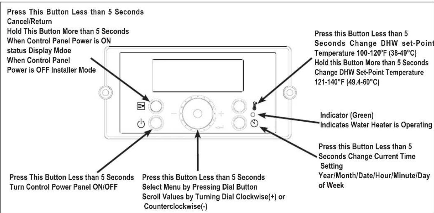
Figure 32 – Water Heater Control Panel Detail
• B. LCD DISPLAY DESCRIPTIONS

Figure 33 – LCD Display Detail
LCD also features a backlit lamp that will illuminate:
- When a user action is detected (a button is pressed)
- The display will turn off after approximately 20 seconds if no buttons are pressed

Figure 34 – Example Display
C. START-UP SEQUENCE
After the appliance is powered ON, the LCD display shows a sequence of information. The icons will flash, followed by various indicators that describe the appliance controller and software versions. It will take the appliance roughly 15 seconds to cycle through the Start-Up Sequence.
| Display Items Time for Display Remarks | ||
| LCD Test | 1 Sec All segments "ON" | |
| 0.5 Sec All segments "OFF" | ||
| Category: 199 | 1 Sec Pdn | |
| 1 Sec 0061 | ||
| Software Version for Front Panel | 1 Sec SPn | |
| 1 Sec 00.XX | ||
| Software Version for Water Heater | 1 Sec SFn | |
| 1 Sec XX.XX | ||
| Hardware Version for Water Heater | 1 Sec Hdn | |
| 1 Sec 00XX | ||
Table 24 – Start-Up Sequence
The Control System can operate through user and service modes that have specific LCD outputs and dedicated controls, including:
- Changing the Set-Point Temperature
- Error Mode
- Status Display Mode
- Installer Mode
• High Elevation Mode
• High Temperature Mode
NOTE: The Control System will not allow changes if Lock Mode is activated unless the button is pressed for more than 5 seconds.
NOTE: The setpoint cannot be changed if water is flowing through the unit. Ensure there is no demand on the water heater when changing setpoint.
The display shows the icon when the DHW set-point can be changed.
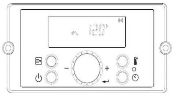
natural_image
Front view of a control panel with buttons, dials, and a central rotary knob (no readable text or symbols)Press the 📋 button when the display panel is powered ON to change the DHW Set-Point. The DHW icon and current set-point will display and flash. This indicates that the DHW Set-Point can be changed. Factory DHW Set-Point is 120°F(49°C). Initial DHW Set-Point range is 100 – 140°F (38 – 60°C).
The recommended starting temperature is 120 °F (49°C).
Turn the dial -○- counterclockwise to lower and clockwise to raise the DHW set-point. After changing the temperature, press the button to save the set-point.
To change the DHW Set-Point above 121°F (49.5°C), press and hold the 🎨 button when the display panel is powered ON.
The current DHW set-point will display. The DHW icon will flash. Then press and hold the button for five seconds. The scald warning letter "H" (High Temperature Warning icon) will display. High temperature DHW Set-Point range is 121irc F – 140irc F ( 49.5irc C – 60irc C).
Turn the dial - counterclockwise to lower and clockwise to raise the DHW set-point. After changing the temperature, press the button to save the set-point.
DANGER
Hotter water increases the risk of scald injury. Scalding may occur within 5 seconds at a setting of 140irc F ( 60irc C). Water temperature over 125irc F can instantly cause severe burns, or death, from scalds. Children, disabled, and elderly are at the highest risk of being scalded. See instruction manual before setting temperature at appliance. Feel water before bathing or showering!
| APPROXIMATE TIME / TEMPERATURE RELATIONSHIPS IN SCALDS | |
| 120°F More than 5 minutes | |
| 125°F | 1 1⁄2 to 2 minutes |
| 130°F | About 30 seconds |
| 135°F | About 10 seconds |
| 140°F | Less than 5 seconds |
| 145°F | Less than 3 seconds |
| 150°F | About 1 1⁄2 seconds |
| 155°F | About 1 second |
E. STATUS DISPLAY MODE
Status Display Mode will activate when button - ○ is pressed and held for five seconds when the display panel is turned on at Standby Mode.
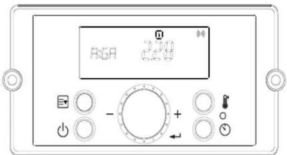
Figure 36 – Status Mode Screens
| Parameter Detail Description | |||
| A:Li or GA Flow Unit | Current Flow Unit(Li: Liters/min, GA: Gallons/min) | ||
| b:Fr | Fan Speed (RPM) Current Fan Speed RPM Value | ||
| C:Lc Lock Mode | Lock Mode is In Use (ON) or Unused (OFF)Allows user to lock out any temperature change. | ||
| d:Op | Operating Temperature Current | Heat Exchanger Operating Temperature | |
| E:dH | DHW Outlet Temperature Current | DHW Outlet Temperature | |
| F:Eh | Exhaust Temperature Current | Exhaust Temperature | |
| H:In | Inlet Water Temperature Current | Inlet Water Temperature | |
| I:rt | PH | Power On Time Power On Time: 1,000 hour increments | |
| rH | Burner Operating Time Burner Operating Time: 1,000 hour increments | ||
| bnCY | Burner Cycles Burner Cycles: 1,000 times unit displayed | ||
| PPHr | Pump Running Time 1,000 hour increments | ||
| J:AG | AGM Adjusts AGM Position: + / - 50 | ||
| K:TA | Time Adjustment | Current Clock Setting | |
Table 25 – Status Mode Display Screen Descriptions – NOTE: Shaded Parameters Not Used on This Software Version
Turn the dial ⚙: counterclockwise and clockwise to scroll through the displayed parameters. To view parameter details, press the button at the appropriate screen. Press the ≡ or ◀ buttons to leave the parameter.
Press the □ button again to return to Operation Mode.
To turn on Lock Mode, press the ◀ button at the C: Lc parameter. Turn the dial ○: counterclockwise and clockwise to scroll On or Off. Press the ◀ button to save the selection and return to the parameters.
Press the □ button again to return to Operation Mode.
NOTE: The Control System will not allow the changes if Lock Mode is activated. Lock Mode will have to be turned off before making further changes
• F. CHANGING THE TIME
Press and hold the button for five seconds when the display panel is powered ON to enter Status Display Mode. Turn the dial: counterclockwise and clockwise to scroll through the displayed parameters to parameter K:TA Press the button to enter and change the time. The time can be adjusted as follows: Year / Month / Date / Hour / Minute / Day of Week.

Figure 37 – Changing the Time Screen
Turn the dial -○: counterclockwise to lower and clockwise to raise the current time setting. After changing the setting, press the ◀ button to save it. The next adjustable setting will appear. After the time settings have been entered, press the □ button to save and return to the Status Display screens.
• G. INSTALLER MODE
Installer Mode will activate when button □ is pressed and held for five seconds while the water heater display is powered Off.
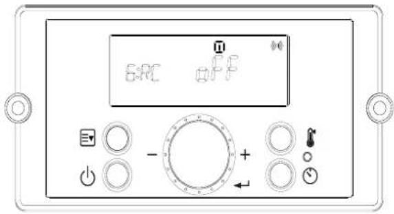
Figure 38- Installer Mode Screens
| Index Default Parameter | Description | ||
| 1:EH N/A Error History | Allows the Installer to View the Unit Error HistoryRange: E0:XX - E9:XX | ||
| 2:CE | Clear Error & System initialize | EHIS :Error History | |
| rH : Burn Hour | |||
| bnCY : Burn Cycle | |||
| PPHr : Pump Running Time | |||
| In: System initialize | |||
| 3:FC GA Unit | Use to choose unit (Water flow rate, Temperature)Lit °C : Liter/minute, CelsiusGAL °F : Gallon/minute, Fahrenheit | ||
| 4:FH 00 Maximum Fan Speed | Adjusts Maximum Fan SpeedRange: -30 - +30 | ||
| 5:FL 00 Minimum Fan Speed | Adjusts Minimum Fan SpeedRange: -30 -+30 | ||
| 6:RC oFF | Recirculation Pump Operation | Turns the Recirculation Pump On and OffRange: On - Pump On, oFF - Pump Off | |
| 7:RM Itnl Recirculation Mode | NOTE: 6:RC must be set to On to select 7:RMSets the Recirculation ModeRange: ItnL - Internal RecirculationEtnL - External Recirculation / On Demand Kit,tt24 - Tiltel 24 Mode, bYPS-Cross over | ||
| 8:RT HI-2 Recirculation Temperature | Sets Recirculation TemperatureRange: LO - Low Temperature, HI-1 - Middle Temperature,HI-2 - High Temperature | ||
| 9:HT HI-2 | Hot Water Temperature | Sets Hot Water TemperatureRange: LO - Low Temperature, HI-1 - Middle Temperature,HI-2 - High Temperature | |
| 10:IV | 6 | Prevent Ignition | Temporarily disables the water heater from igniting for a set period of time.Range: 0 - 20 Minutes |
| 11:HA | 0 - 2 | High Elevation Mode | This water heater may be installed at elevations up to 10,000 feet and operate on either Natural or LP. The appliance will de-rate by 4% for each 1,000 feet above sea level.Select the appropriate installation location as described below.Selects Installation Location for Proper Water Heater Operation at Altitude:0-2 for installation locations from sea level to 2,000 feet2-5 for locations from 2,000 to 5,000 feet5-8 for locations from 5,000 to 8,000 feetDefault: 0 - 2NOTE: Use a combustion analyzer to ensure CO and CO2 are within the ranges shown in this manual. Adjust the offset screw in the clockwise (positive) or counterclockwise (negative) directions (approximately 1/8 turn) if the measured CO2 value on LOW FIRE is out of range. |
| Index Default Parameter | Description | |
| 12:Cn oFF Cascade | Enables Cascade Mode on the water heater.Range: on – Cascade is used, oFF – Cascade is not used | |
| 13: Eh on Common Vent | NOTE: 12:Cn must be set to On to select 13: EhEnables Common Venting on the water heater.Range: on – Common Venting is used,oFF – Common Venting is not used | |
| 14:T1 oFF Test Mode 1 | Used to test the water heater when operating in Internal Recirculation Mode only.The water heater may operate while Test Mode 2 is operating.Range: on, oFF | |
| 15:T2 oFF Test Mode 2 | Used to purge air from the water heating system with an external recirculation pump.The water heater does not need to operate while Test Mode 2 is operating.Range: on, oFF |
Table 26 – Installer Mode Descriptions
Toggle through displayed items by turning the dial -
To change an item, press the Dial button ↩.
Displayed items can be changed by turning the dial -○: counterclockwise to lower, and clockwise to raise, the displayed value.
To save settings, press the Dial button again.
To leave Installer Mode, press button □ again. The water heater will return to power off mode.
H. USING RECIRCULATION MODES – STEP 1
The following section explains and details the use of the Internal / External Recirculation Modes.
Preheat or Internal Recirculation Modes – When calls for hot water are satisfied, the water heater is factory programmed to Preheat and automatically maintain the temperature set point of the water heater – 24 hours a day, 7 days a week. The differential setting can be adjusted to control the temperature set point.
Internal Recirculation Mode allows the installer to program specific recirculation functions by day and time to circulate and heat water more efficiently - when the user most needs hot water. See Recirculation Functions, this manual, for details.
External Recirculation Mode – This mode keeps an external recirculation loop warm to make hot water production more efficient and also aid in freeze protection. An external recirculation line must be installed in order to recirculate water externally. The installer may program specific recirculation functions by day and time to circulate and heat water when the user most needs hot water. See Recirculation Functions, this manual, for details.
To set Recirculation Modes:
- Installer Mode will activate when □ is pressed and held for five seconds while the water heater display is powered Off.
- Turn the dial to 6:RC. Press the Dial button
. "oFF" will flash when the 6:RC setting is ready to be changed. - Turn the dial to "oFF" to turn off the Recirculation Pump, or "on" to turn the Recirculation Pump on.
Press the dial button to select the setting and return to the Installer Mode.

Figure 39 -6:RC - Recirculation Pump Operation

- Next, turn the dial to 7:RM. Press the Dial button. "ItnL" will flash when the 7:RM setting is ready to be changed.
- Turn the dial to "Itnl" to turn on Internal Recirculation Mode, or "Etnl" to use External Recirculation, or "tt24" to use Title 24 application, or "bYPS" to use Bypass Valve. Press the dial button to select the setting and return to the installer Mode.
NOTE: 7:RM can only be selected after 6:RC has been turned on.


Figure 40 - 7:RM - Recirculation Mode
| Setting Detail Description | ||
| Preheat or Internal Recirculation Mode Turns on Internal Recirculation | ||
| External Recirculation Mode or On Demand Application Turns on External Recirculation | ||
| Comply with Title 24 Regulation Turns on External Recirculation | ||
| Applied with Crossover valve included Turn on Internal Recirculation | ||
Table 27 – Internal / External Recirculation Mode Overview
- When finished, press ☑ to exit this menu and turn power back on. Proceed to Step 2 to program the recirculation functions.
- I. SETTING THE RECIRCULATION TIMER – USING RECIRCULATION MODES – STEP 2
NOTICE
Before setting the Recirculation Timer, go into the Installer Mode and change 6:RC from "oFF" to "on". Recirculation Mode will not work if it is not activated in Installer Mode. See Table 28 for Recirculation Timer details.
NOTE: In order to set temperature for external recirculation mode, change from 7:RM to Etnl from installer mode and set one of three options LO (Low temp), HI-1 (Middle temp) and H1-2 (High temp) from 8:RT in installer mode.
! DANGER
Hotter water increases the risk of scald injury. Scalding may occur within 5 seconds at a setting of 140irc F ( 60irc C). Water temperature over 125irc F can instantly cause severe burns, or death, from scalds. Children, disabled, and elderly are at the highest risk of being scalded. See instruction manual before setting temperature at appliance. Feel water before bathing or showering!
There are three Recirculation Timer settings: Act, SEt, and cLr. Act is used to set the Recirculation Timer type. SEt is used to manually set the day and times when the Recirculation Function will be active. cLr is used to clear and reset the Recirculation Timer setting.
The following section details the various Recirculation Timer Functions.
| Step 1: Set the Recirculation Timer Type. | ||
| Setting Detail | Description | |
 |  | Allows the installer to customize the Recirculation Function. The recirculation day and time values must be set in Step 2, SET. |
 | When set in Smart Auto-Learn, the pump will run in Standard Mode for the first seven (7) days. During this period the water heater will monitor and record hot water usage patterns. After the initial seven (7) day learning period, the water heater will use the preceding week's usage pattern to cycle the pump and preheat the water. | |
| Step 2: Set the Recirculation Run Time. | ||
| Setting Detail | Description | |
 |  | Pro9 is a factory set recirculation run time setting with day and time values. This setting can be customized for your installation. Day and Time can be programmed. Default: 6 - 7:30AM, 6 - 7:30 PM |
| Step 3: Reset the Recirculation Run Time setting. | ||
| Setting Setting | Setting | |
 |  | Resets the Pro9 or Auto Recirculation Run Time to the factory settings. |
 | ||
Table 28 – Recirculation Function Overview
- 1. Set the Recirculation Timer Type
a. Enter the Recirculation Timer by pressing ⏻ at Standby Mode while the water heater display is powered on.
b. Press the ◀ button at the "Act" screen to select the Recirculation Timer type. See Figure 41. Turn the dial: to choose between "Auto" or "Pro9".
c. Press the ◀ button to select the Recirculation Timer Type.
d. The Recirculation Timer Type is now set.
NOTE: If "Auto" is selected, the water heater will monitor and record hot water usage patterns over a period of seven (7) days. After this learning period, the water heater will use the usage pattern to automatically cycle the pump and preheat the water.
NOTE: If "Pro9" is selected, continue to step 2 below to set the recirculation run time setting.
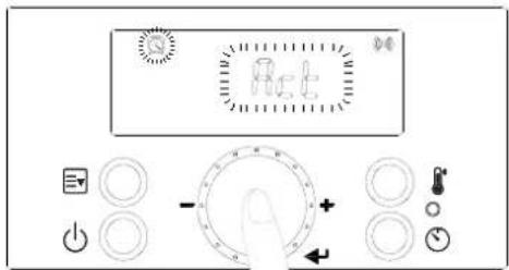
Figure 41 – Setting the Recirculation Timer Type
- 2. Setting the Recirculation Run Time (Pro9 Recirculation Timer)
NOTE: This step is only necessary if "Pro9" was selected as the Recirculation Timer Type. If "Auto" was selected the water heater will automatically program its recirculation operating patterns.
a. Enter the Recirculation Timer by pressing ⏻ at Standby Mode while the water heater display is powered on.
b. Turn the dial - ○: until "SEt" flashes on the screen. Press the ◀ button at the "SEt" screen to set the Recirculation Run Time. See Figure 42.


Figure 42 – Setting the Recirculation Run Time
c. To set the day, ensure "Pro9" is on the display. Turn the dial ⏻: When the desired day appears on the screen, press the ◀ button to select and store the day. Turn the dial ⏻: until the next desired day appears on the display. Press the button to select and store the day. Repeat this step to include more days.
d. Press and hold the ◀ button for two (2) seconds to set the time.
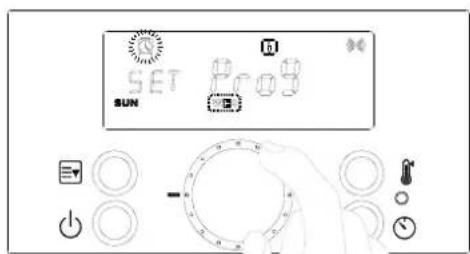

Figure 43 – Setting the Recirculation Day – In this Example, Sunday and Wednesday Are Chosen
e. To set the time, ensure "Pro9" and "12:00" are on the display.

Figure 44 – Setting the Recirculation Time
f. Turn the dial ⏻: The start time on the screen will change in increments of thirty (30) minutes. When the desired start time appears on the screen, press the ◀ button to select and store it. Next, turn the dial ⏻: until the desired end time appears on the display. Press the ◀ button to select and store the end time. Repeat this step to set the start and end times for more days.


Figure 45 – Setting Start and End Recirculation Times
g. Press and hold the ◀ button for two (2) seconds to store the time.
h. If all settings are stored, press ⏻ to return to Standby Mode.

Figure 46- Storing Recirculation Run Time
-3. Resetting the Recirculation Run Time
NOTE: This step is only necessary if the "Pro9" or "Auto" Recirculation Run Times need to be reset. If "Auto" was selected the water heater will automatically program its recirculation operating patterns.
a. Enter the Recirculation Timer by pressing ⏻ at Standby Mode while the water heater display is powered on.
b. Turn the dial - ○: until "cLr" flashes on the screen. Press the ◀ button at the "cLr" screen to reset the Recirculation Run Time.
See Figure 47.

Figure 47 – Resetting the Recirculation Run Time
c. Turn the dial -○: to "Pro9" or "Auto". Press ◀ at the Recirculation Timer Type you wish to reset. See Figure 48.
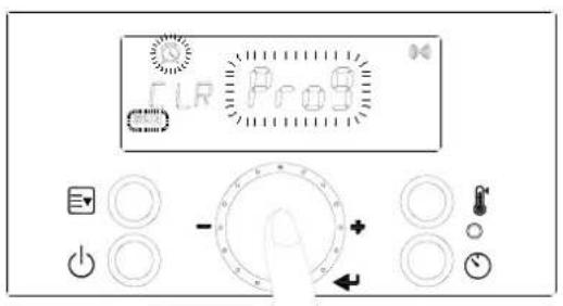

Figure 48 – Resetting the Recirculation Run Time
d. The Recirculation Run Time has now been reset to the factory default settings. Press ⏻ to return to Standby Mode.
NOTICE
If hot water is not used for more than thirty (30) hours, the recirculation program will be stopped and the water heater will automatically go into Vacation Mode and display the vacation icon 📁.
- J. ERROR MODE
When the water heater encounters an error, the display will flash "Er" followed by a numerical code. The water heater shall enter a soft lockout condition if the error is such that it can return to normal operation once the condition relieves itself (overheat conditions, NTC open or shorts, etc.). The water heater shall enter a hard lockout if the condition indicates something more serious (flame, ignition, condensate line, etc.) To clear a hard lockout Error Code, press the Power button. The following screen will display when the water heater encounters an error.

Figure 49 – Error Mode Screen
| Error Code Error Code Description Possible Remedies | ||
| Er:10 | Flame has been lost Eight (8) Times | Press the Power button to clear the Error Code.If Error happens again:1. Monitor the gas pressure to the water heater while in operation.Ensure pressure is between 5.0" W.C and 13.0" W.C (1.25 to 3.24 kPa).2. Check gas valve wire.Ensure connection is secure.3. Check flame detection sensor.Ensure connections are secure.Normal operating settings are more than 2.5DC before ignition, less than 2.5DC after ignition.4. Check igniter transformer for proper connection.5. Clean the spark igniter with steel wool to remove oxides.Ensure proper separation (3-4 mm).6. Replace the spark igniter if damaged.7. Assure that the flame is stable when lit.8. If the problem persists, replace the main control. |
| Er:11 | Ignition has Failed 10 (Ten) Times | Press the Power button to clear the Error Code.If Error happens again:1. Monitor the gas pressure to the water heater while in operation.Ensure pressure is between 5.0" W.C and 13.0" W.C (1.25 to 3.24 kPa).2. Check gas valve wire.Ensure connection is secure.3. Check flame detection sensor.Ensure connections are secure.Normal operating settings are more than 2.5DCbefore ignition, less than 2.5DC after ignition.4. Check igniter transformer for proper connection.5. Clean the spark igniter with steel wool to remove oxides.Ensure proper separation (3-4 mm).6. Replace the spark igniter if damaged.7. Assure that the flame is stable when lit.8. If the problem persists, replace the main control. |
| Er:16 | Operating Temperature Sensor or DHW Sensor detects Water Temperature Greater than 199°F (93°C) | This Error Code will go away when the DHW temperature decreases.If Error happens again:Check if dip switch High Fire setting is ON. Switches 6 and 7 should be OFF for normal operation.Check DHW pipe is blocked. Ensure there is enough water flowing to the water heater.Check DHW sensor at DHW outlet. If resistance is zero, replace the sensor.Check Operating Temperature sensor at the heat exchanger. If resistance is zero, replace the sensor.If the problem persists, replace the main control. |
| Er:20 | High Limit Overheat Switch-Closed is Normal, Open is Fault | Press the Power button to clear the Error Code.Inspect the High Limit Overheat switch. Ensure proper connections.Check High Limit Overheat switch resistance. If resistance is zero, replace the switch.If the problem persists, replace the main control. |
| Er:29 | APS/Condensate-Closed is Normal, Open is Fault(Condensate Drain Trap) | Press the Power button to clear the Error Code.Check APS/Condensate and main controller connections. Ensure all are secure.Check APS/Condensate resistance. If resistance is zero, replace the switch.Check APS/Condensate hose. Ensure it is connected and in good condition.Check condensate line and termination for blockages.Check exhaust vent for blockages.If the problem persists, replace the main control. |
| Er:31 | Water Inlet Sensor Open or Short | This Error Code will go away when inlet water temperature decreases.If Error happens again:Check inlet water temperature sensor. Ensure connections are secure.Check sensor resistance. If resistance is zero, replace the sensor.If the problem persists, replace the main control. |
| Er:32 | Water Outlet Sensor Open or Short | This Error Code will go away when outlet water temperature decreases.If Error happens again:Check DHW outlet temperature sensor. Ensure connections are secure.Check sensor resistance. If resistance is zero, replace the sensor.If the problem persists, replace the main control. |
| Er:33 | H/X Temperature Sensor Open or Short | This Error Code will go away when outlet water temperature decreases.If Error happens again:Check operating temperature sensor. Ensure connections are secure.Check sensor resistance. If resistance is zero, replace the sensor.If the problem persists, replace the main control. |
| Er:35 | Exhaust Sensor Open or Short | This Error Code will go away when exhaust temperature decreases.If Error happens again:Check exhaust temperature sensor. Ensure connections are secure.Check sensor resistance. If resistance is zero, replace the sensor.Check exhaust vent for blockage.If the problem persists, replace the main control. |
| Er:39 | Flame Detected after Exiting a Flame On Condition | This Error Code will go away when the false flame condition is remedied.If Error happens again:Check the water heater cover. Ensure it is secure. Flame detection sensor can detect an external light source.Check flame detection sensor. Ensure connections are secure. Normal operating settings are more than 2.5DC before ignition, less than 2.5DC after ignition.If the problem persists, replace the main control. |
| Er:40 | Gas Leakage continuously detected for 10 Minutes, or three times within One Hour (Greater than 5 Seconds Each Time) | IMPORTANT:If you smell gas, STOP! Follow the instructions on page 2, this manual, and call a qualified service technician or the fuel gas utility.Press the Power button to clear the Error Code.If Error happens again:Check the water heater cover. Ensure it is secure.Check gas connections for leakage with a soapy solution. Fix any leaks.Check condition of the burner assembly.If the problem persists, replace the main control. |
| Er:41 | Fan Speed too High with Flame On | Press the Power button to clear the Error Code.If Error happens again:Check the vent connections for blockages.Check the burner assembly.Check fan operation. If fan appears to be operating normally but RPMs are too low or too high, replace the fan.If the problem persists, replace the main control. |
| Er:43 | Burner Overheat Switch Open | Press the Power button to clear the Error Code.If Error happens again:Check burner overheat switch connections. Ensure connections are secure.Check switch resistance. If resistance is zero, replace the switch.If the problem persists, replace the main control. |
| Er:44 Recirculation Abnormality | Press the Power button to clear the Error Code.If Error happens again:Ensure water heater inlet and outlets are open and water is supplied to the water heater.Check the pump operation.If it doesn't work, ensure wiring connections to pump.If even supply power to pump and doesn't run it replace the pump.If Error happens again:Verify recirculation loop length is within specification. Air purge is not enough.Too much restriction on recirculation loop.Return loops are clogged.Check the recirculation loop condition | |
| Er:45 Water Leak | Turn power off to the water heater.Valve off the water heater to isolate it from the system.Call a qualified service technician to diagnose and repair the source of the leak. | |
| Er:60 | Hot Water Temperature Abnormality | Press the Power button to clear the Error Code.If Error happens again:Ensure water heater inlet and outlets are open and water is supplied to the water heater.If Error happens again:Ensure water heater inlet and outlets are open and water is supplied to the water heater.Check the pump operation.If it doesn't work, ensure wiring connections to pump.If even supply power to pump and doesn't run it, replace the pump.If Error happens again:Verify recirculation loop length is within specification. Air purge is not enough.Too much restriction on recirculation loop.Return loops are clogged.Check the recirculation loop condition. |
| Er:61 | Fan Speed Feedback Signal Abnormal | This Error Code will go away when the condition is remedied.If Error happens again:Check the connections to the fan. Ensure all are secure.If the fan does not rotate during the ignition sequence, check for DC15~30V power at the fan connection. If DC15~30V power is present at the control, replace the fan. If the blower does not have DC15~30V power, check power at the control. If DC15~30V power is not present at the control, replace the control.If the problem persists, replace the main control. |
| Er:65 Supply | Water Valve Error | Press the Power button to clear the Error Code.If Error happens again:Turn power OFF and ON at the main power switch internal to the water heater.Check wiring connections to supply water valve. Ensure all are secure.Replace supply water valve.If the problem persists, replace the main control. |
| Er:66 Mixing | Valve Error | Press the Power button to clear the Error Code.If Error happens again:Turn power OFF and ON at the main power switch internal to the water heater.Check wiring connections to mixing valve. Ensure all are secure.Replace mixing valve.If the problem persists, replace the main control. |
| Er:67 AGM Error | Press the Power button to clear the Error Code.If Error happens again:Turn power OFF and ON at the main power switch internal to the water heater.Ensure fan inlet hole is completely open after turning the power OFF and ON.Check wiring connections to the AGM. Ensure all are secure.Check AGM operation.Replace AGM components.If the problem persists, replace the main control. | |
| Er:72 | Flame Signal Detected before Ignition | This Error Code will go away when the condition is remedied.If Error happens again:Check the water heater cover. Ensure it is secure. Flame detection sensor can detect an external light source.Check flame detection sensor. Ensure connections are secure. Normal operating settings are more than 2.5DC before ignition, less than 2.5DC after ignition.If the problem persists, replace the main control. |
| Er:73 DIP Switch is abnormal | This Error Code will go away when the condition is remedied.If Error happens again:Check dip switches. Ensure switches match the ratings plate requirements of the water heater. See dip switch details, this manual, for default settings.If the problem persists, replace the main control. | |
| Er:76 Poor Communication | This Error Code will go away when the condition is remedied.If Error happens again:Check connections from main control to display panel.If the problem persists, replace the display and/or the main control. | |
| Er:78 | Cascade Communication Error | NOTE: This error will only appear in a cascaded system.Turn power OFF and ON at the appliance display panel.If error reappears, ensure all cascaded appliances are powered ON.If error reappears, check Installer Mode parameter 10:Cn at among the both units.Ensure the setting as "on" in 10:Cn of Installer Mode.If error reappears, check the wire cables into the 'Main PCB' connector inside both units.Ensure the connection of cascade cable between both appliances.If there was no problem wiring connection, replace damaged cables.If the problem persists, replace the main control. |
| Er:94 | Exhaust NTC detects Vent Temperature is Greater than 149°F/65°C(185°F/85°C when High Temp set point is Selected) | This Error Code will go away when the condition is remedied.If Error happens again:Check if dip switch High Fire setting is ON. Switches 6 and 7 should be OFF for normal operation.Check exhaust temperature sensor. Ensure connections are secure.Check sensor resistance. If resistance is zero, replace the sensor.Check exhaust vent for blockage.If the problem persists, replace the control.If the problem persists, replace the heat exchanger. |
Table 29 – Diagnostics and Suggested Corrective Actions
WARNING
This water heater is equipped with a blocked vent shutoff system. If Error Codes Er:29, Er:41 or Er:94 occur, turn off the gas valve at the manual shutoff. Check the vent terminations for obstructions. If no obstructions are found, reset the water heater by pressing the power button. If the error continues to occur, call a qualified service technician or the gas supplier to check the water heater. Failure to follow these instructions could result in property damage, personal injury, or death.
K. ERROR TREE ANALYSIS
1. FLAME DETECTION

flowchart
graph TD
A["Flame Detection"] --> B{Operating Conditions}
B -->|YES| C["Blower 'ON'"]
C --> D{Flame Detector}
D -->|YES| E{Flame Detection}
D -->|NO| F["Normal Operation"]
E -->|YES| G["'IT' ON'"]
G --> H["'GV' ON'"]
H --> I{Flame Detection}
H -->|YES| J["Blower 'ON'<br>GV 'OFF'<br>ERROR "E72""]
J --> K{Flame Detection}
K -->|YES| L["Normal Operation"]
K -->|NO| M["Blower 'OFF'<br>GV 'OFF'<br>ERROR "E11""]
M --> N{RESET}
N -->|YES| O["Normal Operation"]
N -->|NO| P["Blower 'ON'"]
P --> Q{Flame Detection}
Q -->|YES| R["Normal Operation"]
Q -->|NO| S["Blower 'ON'<br>GV 'OFF'<br>ERROR "E72""]
S --> T{Flame Detection}
T -->|YES| U["Normal Operation"]
T -->|NO| V["Blower 'ON'<br>GV 'OFF'<br>ERROR "E72""]
V --> W{Flame Detection}
W -->|YES| X["Normal Operation"]
W -->|NO| Y["Blower 'ON'<br>GV 'OFF'<br>ERROR "E72""]
Y --> Z{Flame Detection}
Z -->|YES| AA["Normal Operation"]
Z -->|NO| AB["Blower 'ON'<br>GV 'OFF'<br>ERROR "E72""]
AB --> AC{Flame Detection}
AC -->|YES| AD["Normal Operation"]
AC -->|NO| AE["Blower 'ON'<br>GV 'OFF'<br>ERROR "E72""]
AE --> AF{Flame Detection}
AF -->|YES| AG["Normal Operation"]
AG --> AH{Flame Detection}
AH -->|YES| AI["Normal Operation"]
AH -->|NO| AJ["Blower 'ON'<br>GV 'OFF'<br>ERROR "E72""]
AJ --> AK{Flame Detection}
AK -->|YES| AL["Normal Operation"]
AK -->|NO| AM["Blower 'ON'<br>GV 'OFF'<br>ERROR "E72""]
AM --> AN{Flame Detection}
AN -->|YES| AO["Normal Operation"]
AN -->|NO| AP["Blower 'ON'<br>GV 'OFF'<br>ERROR "E72""]
AP --> AQ{Flame Detection}
AQ -->|YES| AR["Normal Operation"]
AQ -->|NO| AS["Blower 'ON'<br>GV 'OFF'<br>ERROR "E72""]
AS --> AT{Flame Detection}
AT -->|YES| AU["Normal Operation"]
AT -->|NO| AV["Blower 'ON'<br>GV 'OFF'<br>ERROR "E72""]
AV --> AW{Flame Detection}
AW -->|YES| AX["Normal Operation"]
AW -->|NO| AY["Blower 'ON'<br>GV 'OFF'<br>ERROR "E72""]
AX --> AZ{Flame Detection}
AZ -->|YES| BA["Normal Operation"]
AZ -->|NO| BB["Blower 'ON'<br>GV 'OFF'<br>ERROR "E72""]
Figure 50 – Flame Detection Error Analysis Tree
2. GAS DETECTION
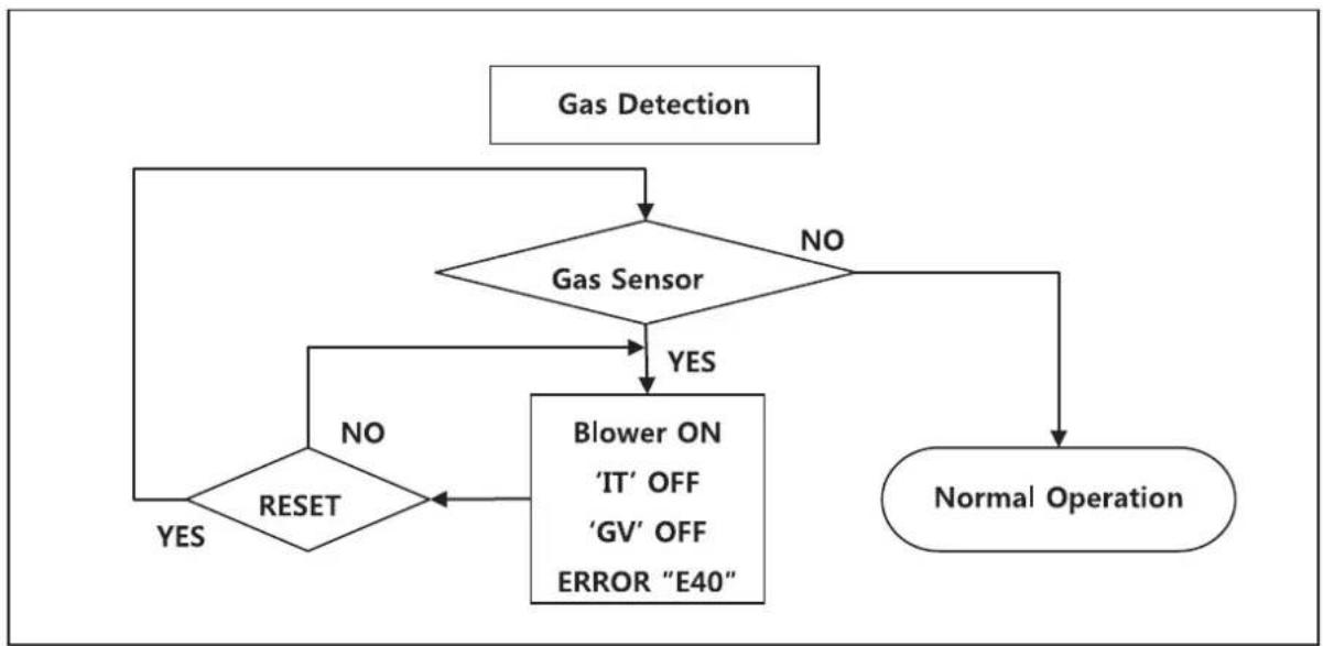
flowchart
graph TD
    A["Gas Detection"] --> B{Gas Sensor}
    B -->|NO| C["Normal Operation"]
    B -->|YES| D{Blower ON 'IT' OFF 'GV' OFF ERROR "E40"}
    D -->|NO| E{RESET}
    E -->|YES| B
    E -->|NO| B
Figure 51 – Gas Detection Error Analysis Tree
3. AIR PRESSURE SWITCH
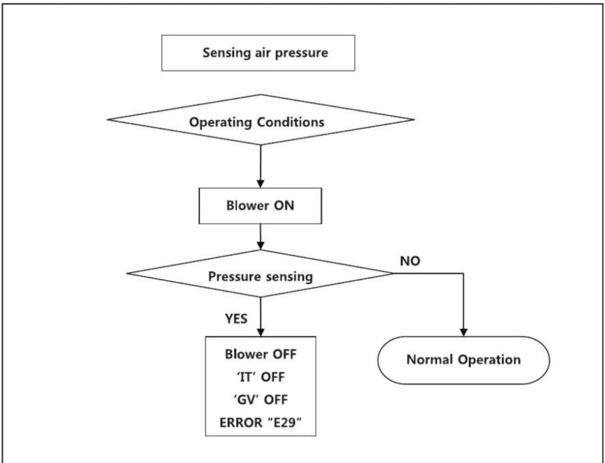
flowchart
graph TD
    A["Sensing air pressure"] --> B{Operating Conditions}
    B --> C["Blower ON"]
    C --> D{Pressure sensing}
    D -->|YES| E["Blower OFF 'IT' OFF 'GV' OFF ERROR "E29""]
    D -->|NO| F["Normal Operation"]
Figure 52 – Air Pressure Switch Analysis Tree
4. Inlet / DHW / Operating Temperature SENSORS

flowchart
graph TD
A["Sensor detects"] --> B{Sensor short}
B -->|YES| C["Blower 'OFF'<br>'IT' OFF<br>'GV' OFF<br>ERROR "xxx""]
B -->|NO| D["Normal operation"]
Figure 53 – Inlet / DHW / Operating Temperature Sensors Error Analysis Tree
FINAL INSTALLATION CHECKLIST
| YES NO | |||
| BEFORE INSTALLING | Is there enough space to ensure proper installation? | ||
| Does installation location allow for proper service clearances? | |||
| Are water and gas lines properly sized and set at proper pressures for the installation? | |||
| Is water heater location as near the exhaust vent / intake pipe terminations as possible? | |||
| Have combustible materials been cleared from the installation location? | |||
| Is there a drain close to the water heater? | |||
| INSTALL WATER PIPING | Does water heater loop piping meet the minimum sizing requirements listed? | ||
| NOTE: Smaller piping will cause performance problems. | |||
| Has water chemistry been checked? | |||
| Does water chemistry meet requirements? | |||
| If water chemistry does not meet requirements, have treatment measures been put in place? | |||
| Has the system been cleaned and flushed? | |||
| INSTALL EXHAUST VENT AND INTAKE PIPING | Has the water heater been vented with the approved materials listed in this manual (3" [7.6 cm] PVC, CPVC, Polypropylene, etc.) or to meet local codes? | ||
| Is air supply sufficient for proper water heater operation? | |||
| Is total vent piping length within the maximum vent length restriction listed in this manual? | |||
| Have venting lengths been minimized? | |||
| Are terminations properly spaced from windows, doors, and other intake vents? | |||
| Have all vent terminations been installed at least one foot above exterior grade and one foot above normal snow accumulation level? | |||
| Is vent piping properly supported? | |||
| Has vent piping been checked for leaks? | |||
| Has the exhaust vent line been pitched back to the water heater at a rate of 1⁄4" (0.6 cm) per foot? | |||
| Have the exhaust vent and intake pipes been properly installed into the connectors provided on the water heater? | |||
| INSTALL CONDENSATE PIPING / TUBING AND COMPONENTS | Have all condensate line components included with the water heater been installed? | ||
| Is the condensate line piped with the approved materials listed in this manual? | |||
| Has the condensate line been routed to a laundry tub or other drain? | |||
| INSTALL GAS PIPING | Is the gas supply line a minimum of 3⁄4" (1.9 cm) in diameter? | ||
| Is the gas supply line length and diameter adequate to deliver the required BTUs? | |||
| Has gas supply line pressure been measured? | |||
| Does the gas type match the type indicated on the water heater rating plate? | |||
| Has a union and shut-off valve been installed? | |||
| PRESSURE RELIEF VALVES | Have you installed approved pressure relief valves on the hot water outlet near the water heater? | ||
| Is the pressure relief valve in the DHW line at least 3⁄4" (1.9 cm) in diameter? | |||
| WIRE THE WATER HEATER | Connect the power and control wiring per water heater wiring diagram, this manual. | ||
| Have all DIP switches been set on the main water heater board? | |||
| Is electrical connection polarity within water heater requirements? | |||
| Do power specifications meet water heater requirements? 120V AC? | |||
| START-UP, ADJUST, AND TEST | Has the water heater been started? | ||
| If necessary, has the water heater gas valve been adjusted? | |||
| Has the installation been customized per installation location requirements? | |||
| Have all customized system parameters been tested? | |||
| Has proper water heater operation been confirmed? | |||
| BURNER FLAME | Has the burner flame been checked? | ||
| Is the burner flame a proper blue color? | |||
| If the flame does not appear normal, it may need to be cleaned by a qualified service technician. See Figure 54 for flame sight glass window location. | |||
| FINAL INSTALLATION APPROVALS | SIGNED BY TECHNICIAN DATE | ||

Figure 54 – Flame Sight Glass
| DHW Inlet Temperature Sensor (7850P-015) Exhaust Temperature Sensor (7850P-070) | |
| Temperature (°F/ °C) Resistance (Ω) | |
| Resistance (Ω) | |
| -4 / -20 28409 | |
| 5 / -15 22152 | |
| 14 / -10 17408 | |
| 23 / -5 13782 | |
| 32 / 0 10990 | |
| 41 / 5 8824 | |
| 50 / 10 7131 | |
| 59 / 15 5800 | |
| 68 / 20 4747 | |
| 77 / 25 3906 | |
| 86 / 30 3233 | |
| 95 / 35 2690 | |
| 104 / 40 2250 | |
| 113 / 45 1891 | |
| 122 / 50 1598 | |
| 131 / 55 1356 | |
| 140 / 60 1155 | |
| 149 / 65 989 | |
| 158 / 70 850 | |
| 167 / 75 733 | |
| 176 / 80 635 | |
| 185 / 85 552 | |
| 194 / 90 482 | |
| 203 / 95 421 | |
| 212 / 100 370 | |
| DHW Inlet Temperature Sensor (7850P-015) Exhaust Temperature Sensor (7850P-070) | |
| Temperature (°F/ °C) Resistance (Ω) | |
| Resistance (Ω) | |
| -4 / -20 62162 | |
| 5 / -15 48440 | |
| 14 / -10 38045 | |
| 23 / -5 30107 | |
| 32 / 0 23998 | |
| 41 / 5 19261 | |
| 50 / 10 15562 | |
| 59 / 15 12655 | |
| 68 / 20 10353 | |
| 77 / 25 8520 | |
| 86 / 30 7051 | |
| 95 / 35 5867 | |
| 104 / 40 4908 | |
| 113 / 45 4125 | |
| 122 / 50 3485 | |
| 131 / 55 2957 | |
| 140 / 60 2520 | |
| 149 / 65 2157 | |
| 158 / 70 1854 | |
| 167 / 75 1600 | |
| 176 / 80 1386 | |
| 185 / 85 1205 | |
| 194 / 90 1051 | |
| 203 / 95 920 | |
| 212 / 100 808 | |
TROUBLESHOOTING
| TROUBLESHOOTING CHART | ||
| PROBLEM POSSIBLE | CAUSES POSSIBLE REMEDIES | |
| No electrical power to the water heater | 1. Is the plug on the power supply cord unplugged from the electrical outlet?2. Is electrical panel's 10 Amp circuit breaker tripped?3. Is the fuse on the circuit board good?4. Is there a power outage to the home? | 1. Reset the plug.2. Reset the circuit breaker.3. If the display panel is blank, unplug the unit or contact an authorized service technician.4. Contact the power company. |
| No water available when a faucet is opened | 1. Is the water supply valve shut off at the meter (do cold water faucets work)?2. Is the water supply valve near the unit open?3. Is the water pipe frozen?4. Is an error code flashing on the display panel (leak detected)? | 1. Open the closed supply valve.2. Open the water supply valve.3. Turn OFF the unit, close all water valves and the gas valve. Contact an authorized service technician.4. Refer to error code information and contact an authorized service technician. |
| Hot water is not available when the faucet is opened. | 1. Does the water heater have power (plugged in)?2. Is the water heater turned ON?3. Is an error code flashing on the display panel?4. Is the gas supply valve open or shut off at the meter (do other gas devices work)?5. Has the flow sensor failed? | 1. Restore electrical power to the unit.2. Press and hold the Power button to turn the unit ON.3. Refer to the Diagnostic and Error Codes section in this manual.4. Open the gas supply valve.5. Check flow sensor. |
| The water temperature is not hot enough or turns cold during use. | 1. Is the faucet open enough to draw at least 0.6 gallons (2.3L) per minute through the water heater?2. Is an error code flashing on the display panel?3. Is the outlet water temperature set too low? | 1. Open the faucet to allow more water flow.2. Refer to the Diagnostic and Error Codes section in this manual.3. Adjust the outlet water temperature (refer to the procedure in this manual). |
| It takes a long time before hot water flows from the faucet. | Is the faucet some distance from the water heater? | a. Allow time for the cold water already in the pipes to flow from the faucet.b. Have recirculation valves and/or plumbing return line(s) installed and program the unit for recirculation mode. |
| The water is not hot enough. | Is the water temperature set too low? Adjust the temperature setting. | |
| The water at the faucet is too hot. | Is the water temperature set too high? Adjust the temperature setting. | |
| A fan can be heard even when the unit is not operating. | 1. The fan continues to operate after the burner shuts off to clear the exhaust vent of combustion gases.2. The fan may run to help prevent freezing. | 1. This is normal operation – no action is required.2. Protect the water heater from freezing temperatures or shut off and drain the unit. |
| White “smoke” can be seen coming out of the exterior exhaust gas vent. | Depending on the outside temperature, water vapor can be produced as the exhaust is vented. | This is normal operation – no action is required. |
Table 30 – Troubleshooting Chart
DIAGNOSTICS AND SUGGESTED CORRECTIVE ACTIONS
The water heater control is able to record information about the water heater's condition at the time of the ten previous faults or errors. This information is available to view in the Installer Mode under the History screen. The following screens may be displayed when reviewing the water heater history. The table below also includes diagnostic information and possible corrective actions.
| Display Condition | Diagnostic Possible Corrective Actions | ||
| Nothing appears on the display control panel but the fan runs at full speed | Control is not receiving power | Check wiring for short circuit or incorrect wiring | Correct wiring per wiring diagram including connection of transformer to the control |
| Check transformer connection to the control per wiring diagram. Check for 14V output of panel wire | Push the Power button on the control panel | ||
| Nothing appears on the display control panel and no other water heater components are operating | Control is not receiving 120V power | Ensure service switch and/or circuit breaker to water heater is turned ON | Turn on service switch or circuit breaker to power water heater |
| Is there 120V at the service switch | Troubleshoot and correct the power supply to the manual switch | ||
| Is the ON/OFF switch inside the water heater cabinet is turned on | Turn ON the manual power switch inside the water heater cabinet | ||
| Check for 120V at the line voltage terminal block located inside the water heater cabinet | Correct wiring inside the water heater cabinet using the wiring diagram in the installation manual | ||
| Inspect the fuse. Replace as necessary | Replace the fuse with the proper part found in the replacement part section of this manual. If fuse blows again, recheck the wiring per diagram | ||
| Nothing appears on the display control panel, but the water heater is operating | Occurs when communications is lost from the control to the display | Check for loose connections and proper pin alignment / engagement on the control's plug | Check for continuity on the wire harness from the display to the control. See repair parts section for proper replacement part. |
| Cycle power off and on using water heater power switch and check for operation | Replace with new display module. See repair parts section for proper replacement part. | ||
| Display repeatedly goes through initialization sequence | Occurs when control does not receive signal from fan | Cycle power off and on using appliance power switch and check for operation | Replace fan. |
Table 31 – Diagnostics and Suggested Corrective Actions
MAINTENANCE PROCEDURES
DANGER
The water heater must be inspected and serviced annually, preferably at the start of the heating season, by a qualified service technician. In addition, the maintenance and care of the water heater as outlined in this manual must be performed by the user/owner to assure maximum efficiency and reliability. Follow the maintenance procedures given throughout this manual. Failure to perform the service and maintenance or follow the directions in this manual could damage the water heater or system components, resulting in substantial property damage, severe personal injury, or death.
! DANGER
To prevent the potential of substantial property damage, severe personal injury, or death, eliminate all the materials listed in Table 1 from the area surrounding the water heater and the vicinity of the combustion air intake. If contaminates are found:
- Remove products immediately from area.
- If contaminates have been there for an extended period, call a qualified service technician to inspect the water heater for possible damage from acid corrosion.
If products cannot be removed, immediately call a qualified service technician to re-pipe the combustion air intake piping away from the contaminated areas.
Combustible/Flammable Materials
Do not store combustible materials, gasoline, or other flammable vapors or liquids near the water heater. If found, remove these materials immediately.
Air Contaminates
If allowed to contaminate combustion air, products containing chlorine or fluorine will produce acidic condensate that will cause significant damage to the water heater. Read the list of potential contaminants and areas likely to have these contaminants in Table 1. If any of these contaminants are in the room where the water heater is located, or combustion air is taken from one of the areas listed, the contaminants must be removed immediately or the intake pipe must be relocated to another area.
Ensure the Water Heater Cabinet is Closed
Ensure the water heater cabinet is closed. Tighten the two upper and lower screws to secure it. The cabinet must be closed while the water heater is running.
Check the Power Source
Make sure the power cord is properly connected. The main power line is connected to the manual switch box inside the water heater. Check the Status of the Control Panel
Observe the Control Panel to ensure the water heater is powered on, and to check for any error codes. Clear any debris from the panel.
Check Exhaust Vent and Intake Pipe Terminations
Verify that the water heater exhaust vent and intake pipe terminations are clean and free of obstructions. Remove any debris from the exhaust vent or intake pipe openings. If removing the debris does not allow the water heater to operate correctly, contact your qualified service technician to inspect the water heater and the vent system.
Check Exhaust Vent and Intake Piping
Visually inspect the exhaust vent for any signs of blockage, leakage, or deterioration of the piping. Inspect the exhaust vent bracing. Ensure bracing is undamaged and in good condition. Notify a qualified service technician immediately if any problems are found.
WARNING
Failure to inspect the venting system and have it repaired by a qualified service technician can result in vent system failure, causing severe personal injury or death.
Visually inspect the intake piping for any signs of blockage. Inspect the entire length of the intake pipe to ensure piping is intact and all joints are properly sealed. Inspect the intake pipe bracing. Ensure bracing is undamaged and in good condition. Notify a qualified service technician if any problems are found.
Check Pressure Relief Valve
- Visually inspect the primary pressure relief valve and discharge pipe for signs of weeping or leakage.
- If the pressure relief valve often weeps, the expansion tank may not be operating properly. Immediately contact a qualified service technician to inspect the water heater and system.
Check the Condensate Drain System
- While the water heater is running, check the discharge end of the condensate drain tubing. Ensure no flue gas is leaking from the condensate drain tubing by holding your fingers near the opening.
- If you notice flue gas leaking from the opening, this indicates a dry condensate drain trap. If problem persists, contact a qualified service technician to inspect the water heater and condensate line and refill the condensate trap.
- If applicable, check the condensate neutralizer and ensure it is full of condensate neutralizing marble chips.
Cleaning the Air Intake Filter
The air intake filter should be cleaned once a month. If not, the water heater could encounter combustion problems.
To clean the air intake filter:
- Press the Power button on the control panel to turn off the water heater.
- Disconnect the power supply from the water heater.
- If water heater has been operating, wait for it to cool before continuing.
- Remove the front cover of the water heater cabinet.
-
Pull the filter screen screw and pull the filter out of the air intake adapter.
-
Remove the filter from the plastic assembly and clean it with a toothbrush and clean running water. See Figure 55.
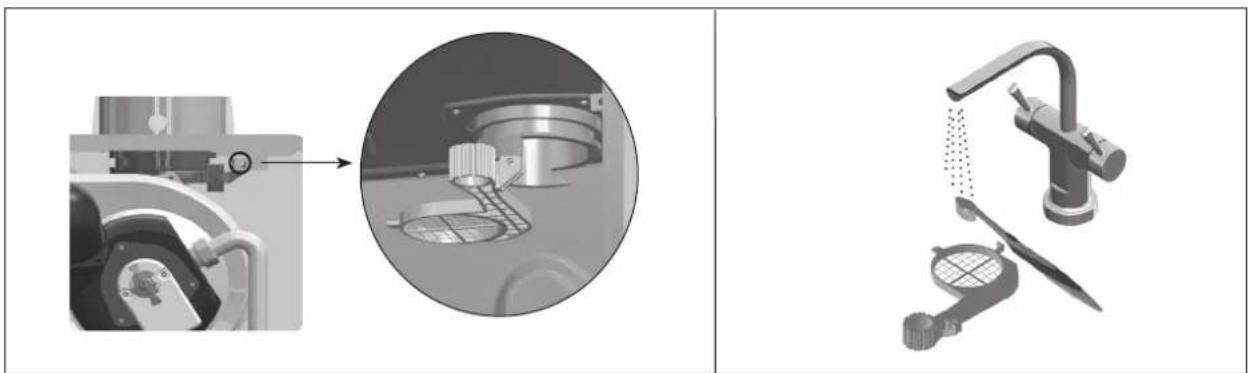
natural_image
Technical illustration of a kitchen cleaning machine with close-up and exploded view (no text or symbols)Figure 55 – Cleaning the Air Intake Filter
- Dry the filter completely. Then reinsert the filter into the plastic assembly.
- Replace the front cover of the water heater cabinet. Reconnect power supply to the water heater.
- Press the Power button on the control panel to turn on the water heater.
Check Primary and Gas Piping
- Remove the water heater cover and perform a gas leak inspection following Operating Instructions, page 2, this manual. If gas odor or leak is detected, follow procedures on page 2. Call a qualified service technician.
- Visually inspect for leaks around the internal water heater water connections and around the heat exchanger. Visually inspect the external system piping, circulators, and system components and fittings. Immediately call a qualified service technician to repair any leaks.
WARNING
Have leaks fixed at once by a qualified service technician. Failure to comply could result in substantial property damage, severe personal injury, or death.
Operate Pressure Relief Valve
- Before proceeding, verify that the relief valve outlet has been piped to a safe place of discharge, avoiding any possibility of scalding from hot water.
- Shut power off to the water heater. To avoid scalding, wait for water heater to cool before operating the relief valve.
WARNING
To avoid water damage or scalding due to relief valve operation, a discharge line must be connected to the valve outlet and directed to a safe place of disposal. This discharge line must be installed by a qualified service technician or heating/plumbing installer in accordance with the water heater installation manual. The discharge line must be terminated so as to eliminate possibility of severe burns or property damage should the valve discharge.
- List the relief valve lever. If water flows freely, release the lever and allow the valve to seat. Watch the end of the relief valve discharge pipe to ensure that the valve does not weep after the line has had time to drain. If the valve weeps, lift the lever again to attempt to clean the valve seat. If the valve does not properly seat and continues to weep, contact a qualified service technician to inspect the valve and system.
- If water does not flow from the valve when you completely lift the lever, the valve or discharge line may be blocked. Immediately shut the water heater down per instructions on page 2 and call a qualified service technician to inspect the valve and system.
- If relief valve seats properly, restore power to the water heater. Observe operation for five minutes and ensure it operates properly.
Check the Burner
Clean the exterior of the burner.
Cleaning the Cold Water Inlet Filter (Draining the Water Heater)
- Place a bucket under the appliance to collect the residual water inside the water heater.
- Press the Power button on the control panel to turn off the electrical power to the water heater. Then turn off the gas valve.
- Valve off the water heater from the system. If the water heater cannot be isolated from the system, turn off the main water valve. Open the hot water faucets in the system to aid in draining the system.
- Use a coin to remove the cold water inlet filter. Then clean it with a toothbrush and clean running water. See Figure 56.

natural_image
Two-panel diagram showing a device with a black arrow pointing to a component, no text or symbols present.Cold Water Filter


natural_image
Diagram of a showerhead fixture with attached components and wiring (no text or symbols)Figure 56 – Draining the Water Heater
- Reinstall the cold water inlet filter.
- Restore water service to the water heater by opening the isolation valves, or turning on the main water valve.
- Turn on the gas valve. Turn on electrical power to the water heater and press the Power button to turn the water heater on.
Flushing the Water Heater
Flushing the heat exchanger is a complicated procedure that should only be performed by a qualified service technician.
NOTE: Improper maintenance WILL VOID water heater warranty.
- Disconnect electrical power to the water heater.
- Close the shutoff valves on both hot water outlet and cold water inlet lines (V1 and V2). See Figure 57.
- Connect one hose (D1, Figure 57) to the valve (V3) and place the free end in a bucket. Connect one of the hoses (D3) to the circulation pump outlet and the cold water inlet line to valve V4. Connect the other hose (D2) to the circulation pump inlet and place the free end in the bucket.


Figure 57 – Flushing the Water Heater
- Pour tankless water heater cleaning solution into the bucket. Ensure the cleaning solution is approved for potable water systems. Place the drain hose (D1) and hose D2 to the pump inlet in the cleaning solution.
- Open service valves (V3 and V4) on the hot water outlet and cold water inlet lines.
- Turn on the circulation pump. Operate the pump and allow the cleaning solution to circulate through the water heater for at least 1 hour at a rate of 4 gallons per minute. This will remove any possible harmful scale deposits.
- Rinse the cleaning solution from the combination water heater as follows:
a. Remove the free end of drain hose D1 from the bucket.
b. Close service valve V4 and open shutoff valve V2.
c. Do not open shutoff valve V1.
d. Allow water to flow through the water heater for 5 minutes.
e. Close shutoff valve V2.
-
Disconnect all hoses.
-
Remove the cold water inlet filter from the water heater and clean out any residues.
- Reinsert the filter and ensure the filter cap is securely tightened.
- Connect electrical power to the water heater.
- Open a hot water faucet. Run the water heater continuously for five minutes to ensure all cleaning solution is purged from the system. Check for leaks and ensure the water heater is operating properly.
REPLACEMENT PARTS

| Ref # | Description |
| 1. | Front Cover |
| 1-1. | Control Panel Bracket |
| 1-2. | Control Panel Window |
| 2. | PCB |
| 3. | Control Panel |
| 4. | Circulation Pump |
| 5. | Mixing Valve |
| 6. | Igniter |
| 7. | Gas Valve Assembly |
| 8. | Burner Assembly |
| 9. | Blower & Silencer |
| 10. | Flow Control Valve |
| 11. | Air Pressure Switch |
| 12. | Water Leak Detector |
| Ref # | Description |
| 13. | Hot Water Pipe Assembly |
| 14. | Rocker Switch |
| 15. | Condensate Trap |
| 16. | Exhaust Assembly |
| 17. | Air Intake Assembly |
| 18. | Air Intake Filter |
| 19. | Cold Water Valve Assembly |
| 20. | Recirculation Return Connection |
| 21. | Check Valve |
| 22. | Gas Inlet Connection |
| 23. | Control Panel Steel Bracket |
| 24. | Terminal Block |
Table 32 – Cabinet Replacement Parts
LIMITED WARRANTY
For the RHEEM®, RUUD®, Richmond®, Paloma®, and Sure Comfort® Residential Tankless Gas Water Heaters.
EXCLUSIVE WARRANTY - LIMITATION OF LIABILITY
This Limited Warranty is the only Warranty for this unit given by the Water Heater Division of Rheem Manufacturing Company. No one is authorized to make any other warranties on behalf of Rheem. ANY IMPLIED WARRANTIES, INCLUDING MERCHANTABILITY, OR FITNESS FOR A PARTICULAR PURPOSE, SHALL NOT EXTEND BEYOND THE APPLICABLE WARRANTY PERIODS, SPECIFIED PREVIOUSLY. RHEEM'S SOLE LIABILITY, WITH RESPECT TO ANY DEFECT, SHALL BE AS SET FORTH IN THIS LIMITED WARRANTY, AND ANY CLAIMS FOR INCIDENTAL OR CONSEQUENTIAL DAMAGES (INCLUDING DAMAGE FROM WATER LEAKAGE)
ARE EXCLUDED. Some states do not allow limitations on how long an implied warranty lasts, or for the exclusion of incidental or consequential damages, so the above limitations or exclusions may not apply to you.
This Limited Warranty gives you specific legal rights, and you may also have other rights, which vary from state to state.
We suggest you immediately complete the information below and retain this Certificate of Limited Warranty in the event warranty service is needed. Reasonable proof of the date of installation of your water heater may be required to establish its "in-warranty" status.
GENERAL
This Limited Warranty is only available to the original owner of the water heater at the original installation location. It is not transferable.
Rheem Manufacturing Company (Rheem) warrants this tankless gas water heater, and its component parts, to be free from defects in materials and manufacture, under normal use and service, for the Applicable Warranty Periods. At its option, Rheem will repair or replace the defective water heater, or defective component part(s), in accordance with the terms of this Limited Warranty, if it fails in normal use and service during the Applicable Warranty Periods. The replacement water heater must be manufactured by Rheem under one of the covered brand names. The replacement component part(s) must be Rheem authorized component part(s). The replacement unit will be warranted only for the unexpired portion of the original unit's Applicable Warranty Periods.
Rheem strongly recommends that this tankless water heater be installed by a contractor which is licensed, state qualified and trained on Rheem's tankless products since improper installation may invalidate warranty coverage.
EFFECTIVE DATE
The Effective Date of warranty coverage (or the beginning of the Applicable Warranty Periods) is the date of installation of the water heater, if properly documented. Otherwise, it is the date of manufacture of the water heater plus ninety (90) days.
APPLICABLE WARRANTY PERIODS:
Residential: a Single Family Dwelling
Twelve (12) years from the Effective Date for the heat exchanger, five (5) years from the Effective Date for the component parts, and one (1) year for certain labor as described under the heading, LABOR, SHIPPING AND PROCESSING COST.
Residential: a Single Family Dwelling used with Hydronic Force Air Heating
Ten (10) years from the Effective Date for the heat exchanger, five (5) years from the Effective Date for the component parts, and one (1) year for certain labor as described under the heading, LABOR, SHIPPING AND PROCESSING COST. Provided that a Rheem manufactured/ Rheem approved potable water hydronic air handler is installed with the system.
Residential: a Single Family Dwelling with recirculation, controlled loop
Twelve (12) years from the Effective Date for the heat exchanger, five (5) years from the Effective Date for the component parts, and one (1) year for certain labor as described under the heading, LABOR, SHIPPING AND PROCESSING COST. Provided that the recirculation system is an on demand type system or the pump is controlled with a temperature sensor (aquastat) and timer.
Residential: a Single Family Dwelling with recirculation, uncontrolled loop
Three (3) years from the Effective Date for the heat exchanger, three (3) years from the Effective Date for the component parts, and one (1) year for certain labor as described under the heading, LABOR, SHIPPING AND PROCESSING COST, if the water heater is installed in a system in which the water is re-circulated using a continuously operating pump.
Commercial: any installation that is not a single family dwelling
Five (5) years from the Effective Date for the heat exchanger, five (5) years from the Effective Date for the component parts, and one (1) year for certain labor as described under the heading, LABOR, SHIPPING AND PROCESSING COST.
Commercial: with recirculation, controlled loop
Five (5) years from the Effective Date for the heat exchanger, five (5) years from the Effective Date for the component parts, and one (1) year for certain labor as described under the heading, LABOR, SHIPPING AND PROCESSING COST. Provided that the recirculation system is an on demand type system or the pump is controlled with a temperature sensor (aquastat) and timer.
Commercial: with recirculation, uncontrolled loop
Three (3) years from the Effective Date for the heat exchanger, three (3) years from the Effective Date for the component parts, and one (1) year for certain labor as described under the heading, LABOR, SHIPPING AND PROCESSING COST, if the water heater is installed in a system in which the water is re-circulated using a continuously operating pump.
WARRANTY EXCLUSIONS
This Limited Warranty will not cover
a) Service trips to your business to teach you how to install, use, or maintain this water heater or to bring the water heater installation into compliance with local building codes and regulations or manufacture installation requirements.
b) This tankless water heater if it is installed for use in: spa or pool heating; a recreational vehicle; a boat or any other watercraft.
c) Units installed in any circulating system in which the temperature of the incoming water to the water heater is in excess of 140° f.
d) This tankless water heater if it is installed in any installation supplying radiant heat, such as in floor, baseboard, radiators, snow melt or closed loop systems, or any system using glycol or non-potable water.
e) Damages, malfunctions or failures resulting from failure to install the water heater in accordance with applicable building codes/ordinances or good plumbing and electrical trade practices.
f) Damages, malfunctions or failures resulting from improper installation or failure to operate and maintain the unit in accordance with the manufacturer's instructions provided including outside recommended water quality levels:
g) Performance problems caused by improper sizing of the water heater or the gas supply line, the venting connection, combustion air openings, electric service voltage, wiring, or fusing.
h) Damages, malfunctions or failures caused by improper conversion from natural gas to LP gas or LP gas to natural gas fuel source.
WARRANTY EXCLUSIONS (CONTINUED)
This Limited Warranty will not cover:
i) Damages, malfunctions or failures caused by operating the water heater with any parts removed or with modified, altered, or unapproved parts installed.
i) Damages, malfunctions or failures caused by abuse, accident, fire, flood, freeze, lightning, acts of God and the like.
k) Heat exchanger failures (leaks) caused by operating the water heater in a corrosive or contaminated atmosphere or damages, malfunctions or failures caused by lime, mineral build-up, or scale.
I) Damages, malfunctions or failures caused by operating the unit at water temperatures exceeding the maximum setting of the operating, or high limit, control.
m) Heat exchanger failures caused by operating the water heater when it is not supplied with potable water, free to circulate at all times.
n) Damages, malfunctions or failures caused by subjecting the heat exchanger to pressures, or firing rates, greater than those shown on the rating label.
o) Damages, malfunctions or failures resulting from the use of any attachment, including any energy saving device, not authorized by Rheem.
p) Units installed outside the fifty states (and the District of Columbia) of the United States of America and the Dominion of Canada.
q) Units removed from the original installation location and reinstalled elsewhere.
r) Units that have had their rating labels altered, tampered with, or removed. A water heater should not be operated if the rating label is removed.
LABOR, SHIPPING, AND PROCESSING COSTS
For one (1) year after the Effective Date, Rheem will cover reasonable labor costs necessary to repair or replace a tankless water heater or component part it determines to be defective in material and/or manufacture by a contractor which is licensed, state qualified, and trained for Rheem's tankless water heaters. This Limited Warranty does not cover any labor expenses for general service, inspection, reinstallation, permits, removal and disposal of the failed water heater or defective component part(s), or updating the installation to meet manufacture or local code requirements. All such expenses are your responsibility.
Rheem will pay the transportation costs for an "in-warranty" replacement water heater, or "in-warranty" replacement component
part(s), to a convenient delivery point (selected by Rheem) near the place the original water heater, or original component part(s), is located: such as a local water heater distributor. You must pay any local freight charges, including the cost of returning the failed water heater, or defective component part(s) to a convenient shipping location (selected by Rheem): such as a local Rheem distributor.
Rheem does not authorize, recommend, or receive any benefit from any claims processing or similar fees charged by others to process warranty claims for any water heater or component part(s). Rheem will not reimburse any party for these, or any other, fees not specifically covered in this Limited Warranty document.
HOW TO OBTAIN WARRANTY CLAIM ASSISTANCE
Any claim for warranty assistance must be made promptly. First, determine if your water heater is "in-warranty" (that is, within the Applicable Warranty Period). You can determine your unit's warranty status by adding its Applicable Warranty Period to its date of installation. However, if you do not have documentary proof of your water heater's date of installation, your unit's warranty status will be based on its date of manufacture as determined from the serial number.
Add the Applicable Warranty Period plus ninety (90) days to the date of manufacture to determine whether the water heater is still covered by this Limited Warranty. You may also determine your unit's warranty status by obtaining the complete model number, complete serial number, and date of installation of your water heater and then accessing the "Warranty Verification" information on Rheem Water Heaters' internet website (www.rheem.com) or contacting Rheem's Claims Department (telephone (800) 621-5622) during normal business hours (in the Central Time Zone) to determine if the Applicable Warranty Period has expired.
If your water heater is "in-warranty", contact the plumber, or mechanical contractor, that installed it for assistance with the warranty repairs, or replacement, required. Rheem Water Heaters' Technical Service personnel are available to assist you (by telephone at (800) 432-8373 or via e-mail at techserv@rheem.com) in obtaining "in-warranty" service or to answer your questions about the operation or repair of your water heater during normal business hours (in the Central Time Zone). Be prepared to provide the plumber, mechanical contractor, or Rheem Technical Service person you call with the complete model number, the complete serial number, and the date of installation of your water heater in addition to an explanation of your water heater problem.
If an exact replacement is not available, Rheem will provide you with the current model of your water heater, or component part(s), or a replacement unit with comparable operating features. If government regulations or industry certification or similar standards require the replacement water heater, or replacement component part(s), to have features not found in the defective water heater, or the defective component part(s), you will be charged for the difference in price represented by those required features. If you pay the price difference for those required features and/or to upgrade the size and/or other features available on a replacement new water heater, you will also receive a complete new Limited Warranty (with the full Applicable Warranty Periods) for the replacement new water heater.
Rheem reserves the right to inspect, or require the return of, the failed water heater or the defective component part(s). Each "in-warranty" failure water heater must be made available to Rheem (with the rating label and all the component parts intact) in exchange for the replacement water heater. Each defective "in-warranty" component part to be replaced must be returned to Rheem in exchange for the replacement component part.
Warranty compensation is subject to validation of "in-warranty" coverage by Rheem Claims Department personnel.
- To obtain warranty compensation for an "in-warranty" water heater failure, you must provide Rheem with the failed water heater (with the rating label and all the component parts intact) the complete model number and the complete serial number of the Rheem or Ruud water heater that replaced the failed unit; and the date the original water heater failed. You may also be required to provide documentary proof of the failed water heaters date of installation to establish its "in-warranty" status.
- To receive warranty compensation for an "in-warranty" defective component part, you must provide Rheem with: the defective component part; the complete model number and the complete serial number of the Rheem or Ruud water heater from which the defective component part was removed; and the date the defective component part failed. You may also be required to provide documentary proof of the date of installation of the Rheem or Ruud water heater from which the defective part was removed – or the date of purchase of the part (If it was purchased separately) – to establish the "in-warranty" status of the defective component part.
- If Rheem determines that the water heater or component part returned to Rheem is free of defects in material and manufacture and/or that it was damaged by improper installation, the warranty claim for the product, component part and/or labor maybe denied. Warranty claim documentation should be mailed promptly to Rheem Water Heaters, Claims Department,800 Interstate Park Drive, Montgomery, Alabama 36019, or in Canada, 125 Edgeware Rd. Unit 1, Brampton, ON, Canada L6Y 0P5
DO NOT RETURN THIS WATER HEATER OR PART TO RHEEM WITHOUT A RETURN AUTHORIZATION.
This document is for reference only and does not replace the original warranty document found in the back of the Use and Care manual provided with the tankless water heater.
In keeping with its policy of continuous progress and product improvement, Rheem reserves the right to make changes without notice.
Rheem Water Heating • 800 Interstate Park Drive
Montgomery, Alabama 36019 • www.rheem.com
Rheem Canada Ltd./Ltée • 125 Edgeware Road, Unit 1
Brampton, Ontario L6Y 0P5 • www.rheem.com
WARNING
Allowing the water heater to operate with a dirty combustion chamber will hurt operation. Failure to clean the heat exchanger as needed by the installation location could result in water heater failure, property damage, personal injury, or death. Such product failures ARE NOT covered under warranty.
The water heater requires minimal periodic maintenance under normal conditions. However, in unusually dirty or dusty conditions, periodic vacuuming of the cover to maintain visibility of the display and indicators is recommended.
Periodic maintenance should be performed once a year by a qualified service technician to assure that all the equipment is operating safely and efficiently. The owner should make necessary arrangements with a qualified heating contractor for periodic maintenance of the water heater. Installer must also inform the owner that the lack of proper care and maintenance of the water heater may result in a hazardous condition.
| INSPECTION ACTIVITIES DATE LAST COMPLETED | |||||
| Piping | 1st YEAR | 2nd YEAR | 3rd YEAR | 4th YEAR | |
| Near water heater piping | Check water heater and system piping for any sign of leakage. Leaking pipes could cause property damage. Make sure all piping is properly supported. Flush tankless heat exchanger annually (more in hard water conditions). See User's Information manual for instructions. | ||||
| Vent | Check condition of all vent pipes and joints. Ensure all vent piping is properly supported. Check for obstructions exhaust and intake termination points. | ||||
| Gas | Check Gas piping, test for leaks and signs of aging. Make sure all pipes are properly supported. | ||||
| SYSTEM | |||||
| Visual Do a full visual inspection of all system components. | |||||
| Functional Test all functions of the system (Heat, Safeties) | |||||
| ELECTRICAL | |||||
| Connections Check wire connections. Make sure they are tight. | |||||
| Switch and Plug Verify ON/OFF switch and convenience plug are both functional | |||||
| CHAMBER/BURNER | |||||
| Combustion Chamber | Check burner tube and combustion chamber coils. Clean according to maintenance section of manual. Vacuum combustion chamber. | ||||
| Spark Electrode Clean Set gap at 1/8" (0.3 cm). | |||||
| CONDENSATE | |||||
| Condensate Trap Clean debris from the condensate trap. Fill with clean water. | |||||
| Neutralizer Check condensate neutralizer. Replace if necessary. | |||||
| Condensate hose | Disconnect condensate hose. Clean out dirt and re-install. (NOTE: Verify the flow of condensate, making sure that the hose is properly connected during final inspection.) | ||||
| GAS | |||||
| Pressure | Measure incoming gas pressure (NG : 5.0" to 10.5" W.C.) (LP : 9.5" to 13.0" W.C.) | ||||
| Check gas pipe for leaks | Check piping for leaks. Verify that all are properly supported. | ||||
| COMBUSTION | |||||
| CO/CO2Levels | Check CO and CO2 levels in Exhaust. Record at high and low fire. | ||||
| SAFETIES | |||||
| ECO (Energy Cut Out) | Check continuity on Flue and Water ECO. Replace if corroded. | ||||
| FINAL INSPECTION | |||||
| Check list | Verify that you have completed entire check list. WARNING: FAILURE TO DO SO COULD RESULT IN SERIOUS INJURY OR DEATH. | ||||
| Homeowner | Review what you have done with the homeowner. | ||||
| TECH SIGN OFF | |||||
Table 34 - *Continue annual maintenance beyond the 4th year as required.
CUSTOMER INSTALLATION RECORD FORM
The following form should be completed by the installer for you to keep as a record of the installation in case of a warranty claim. After reading the important notes at the bottom of the page, please also sign this document.
| Customer's Name: | |
| Installation Address: | |
| Date of Installation: | |
| Installer's Code/Name: | |
| Product Serial Number(s): | |
| Combustion Setting at Time of Installation: | |
| Comments: | |
| Installer's Phone Number: | |
| Signed by Installer: | |
| Signed by Customer: |
IMPORTANT NOTES:
Customer: Please only sign after the installer has reviewed the installation, safety, proper operation and maintenance of the system. In the case that the system has any problems, please call the installer. If you are unable to make contact, please contact your Sales Representative.
Distributor/Dealer: Please insert contact details.
- WARNING
- FOR YOUR SAFETY!
- WHAT TO DO IF YOU SMELL GAS
- OPERATING INSTRUCTIONS
- TO TURN OFF GAS TO APPLIANCE
- ! DANGER
- CAUTION
- IMPORTANT
- - FOREWORD
- - FOR THE INSTALLER
- INSTALLATIONS MUST COMPLY WITH:
- TABLE OF CONTENTS
- USER'S INFORMATION......7
- THE FOLLOWING ARE INSTALLATION INSTRUCTIONS FOR THE CONTRACTOR....14
- ITEMS SHIPPED WITH THE WATER HEATER....15
- SAFETY REGULATIONS....15
- SPECIFICATIONS....19
- PREPARE WATER HEATER LOCATION....22
- EXHAUST VENT AND INTAKE PIPE.... 24
- OPERATING SYSTEM INSTRUCTIONS....57
- SETTING THE RECIRCULATION TIMER – USING RECIRCULATION MODES – STEP 2....63
- ERROR MODE....67
- ERROR TREE ANALYSIS......67
- FINAL INSTALLATION CHECKLIST....74
- TROUBLESHOOTING....76
- DIAGNOSTICS AND SUGGESTED CORRECTIVE ACTIONS ....76
- MAINTENANCE PROCEDURES....77
- REPLACEMENT PARTS....81
- Limited Warranty for 180,000 / 199,000Btu/hr Tankless Water Heaters....82
- MAINTENANCE REPORT......84
- MAINTENANCE NOTES......85
- CUSTOMER INSTALLATION RECORD FORM....86
- USER'S INFORMATION
- TO TURN OFF GAS TO THE WATER HEATER
- - 1. BEFORE OPERATION
- - 2. DURING OPERTAION
- Check for Gas Leaks
- Check for Proper Ventilation
- Breathing Hazard - Carbon Monoxide Gas
- Burn Warning
- Combustibles and Flammable Material Warning
- Check for Water Leaks
- - 3. TROUBLESHOOTING AND GENERAL CAUTIONARY STATEMENTS
- DANGER
- MAINTENANCE
- SERVICE TECHNICIAN
- General
- Additional Items if Combustion or Performance is Poor
- OWNER MAINTENANCE
- Periodically
- Monthly
- Every 6 Months
- • C. MAINTENANCE PROCEDURES
- DAILY MAINTENANCE
- Check the Surrounding Area
- Combustible/Flammable Materials
- Air Contaminates
- Ensure the Water heater Cabinet is Closed
- Check the Power Source
- Check the Status of the Control Panel
- Check Exhaust Vent and Intake Pipe Terminations
- MONTHLY MAINTENANCE
- Check Exhaust Vent and Intake Piping
- Check Pressure Relief Valve
- Check the Condensate Drain System
- Cleaning the Air Intake Filter
- To clean the air intake filter:
- MONTH MAINTENANCE
- Check Primary and Gas Piping
- Operate Pressure Relief Valve
- ANNUAL MAINTENANCE
- Check the Burner
- Cleaning the Cold Water Inlet Filter (Draining the Water Heater)
- Flushing the Water Heater
- • D. TROUBLESHOOTING
- THE FOLLOWING ARE INSTALLATION INSTRUCTIONS FOR THE CONTRACTOR
- SAFETY REGULATIONS
- • A. OPERATION AND INSTALLATION WARNINGS
- • B. IMPROPER COMBUSTION
- GAS
- • D. WHEN SERVICING THE WATER HEATER
- • E. WATER CHEMISTRY REQUIREMENTS
- • F. FREEZE PROTECTION
- • H. HIGH ELEVATION INSTALLATIONS
- DIMENSIONS
- PREPARE WATER HEATER LOCATION
- • A. BEFORE LOCATING THE WATER HEATER
- LEVELING
- • C. CLEARANCES FOR SERVICE ACCESS
- • D. RESIDENTIAL GARAGE AND CLOSET INSTALLATIONS
- PRECAUTIONS
- • E. EXHAUST VENT AND INTAKE PIPE
- • F. CARBON MONOXIDE DETECTORS
- In the Commonwealth of Massachusetts and As Required by State and Local Codes
- • G. PREVENT COMBUSTION AIR CONTAMINATION
- • H. REMOVING A WATER HEATER FROM A COMMON VENT SYSTEM
- - I. UNPACKING THE WATER HEATER
- • J. WALL-MOUNTING THE WATER HEATER
- POSITIONING THE WATER HEATER ON THE WALL
- VENTING
- • A. INTAKE PIPE AND EXHAUST VENT GUIDELINES
- NOTE: DO NOT CEMENT POLYPROPYLENE PIPE.
- In the Commonwealth of Massachusetts and as Required by State and Local Codes:
- • B. APPROVED VENT MATERIALS
- • C. Allowed Schedule 40 Vent Length (PVC, CPVC, PP)
- Maximum Vent Length (Intake/outlet)
- Minimum Vent Length (Intake/outlet)
- • D. TIGHTENING WATER HEATER COLLAR TO EXHAUST VENT AND INTAKE PIPE
- • E. VENT TERMINATION
- Screen Installation
- FOR YOUR SAFETY
- Power Venting, Indoor Combustion Air Installation in Confined or Unconfined Space
- VENT DIAMETER SIZING AND LENGTHS
- RECOMMENDED EXHAUST PIPE TRANSITIONS
- TWO PIPE VENT SYSTEM (DIRECT VENT)
- GAS PIPING
- • A. GAS PIPE SIZING TABLES
- Gas Pipe Sizing
- Natural Gas Pipe Sizing
- LP (Liquid Propane) Gas Pipe Sizing
- • B. GAS CONNECTION REQUIREMENTS
- • C. ADDITIONAL PRECAUTION FOR EXCESS FLOW VALVE (EFV)
- • D. ADJUSTING GAS PRESSURE AT THE WATER HEATER
- • E. SETTING AND VERIFYING THE COMBUSTION SETTING
- NOTICE
- WATER PIPING
- GENERAL PLUMBING CONNECTION GUIDELINES
- INSTALL A BACKFLOW PREVENTER
- PIPING THE WATER HEATER
- APPLICATIONS
- Standard Mode
- External Recirculation mode
- Preheat or Internal Recirculation Mode
- • E. PRESSURE RELIEF VALVE
- CONNECT ELECTRICAL POWER / INITIAL STARTUP
- WIRING INFORMATION
- DIP SWITCHES
- • OPERATING SYSTEM INSTRUCTIONS
- CONTROL PANEL
- • B. LCD DISPLAY DESCRIPTIONS
- START-UP SEQUENCE
- STATUS DISPLAY MODE
- • F. CHANGING THE TIME
- • G. INSTALLER MODE
- USING RECIRCULATION MODES – STEP 1
- To set Recirculation Modes:
- - I. SETTING THE RECIRCULATION TIMER – USING RECIRCULATION MODES – STEP 2
- - 1. Set the Recirculation Timer Type
- - 2. Setting the Recirculation Run Time (Pro9 Recirculation Timer)
- -3. Resetting the Recirculation Run Time
- - J. ERROR MODE
- ERROR TREE ANALYSIS
- FLAME DETECTION
- GAS DETECTION
- AIR PRESSURE SWITCH
- Inlet / DHW / Operating Temperature SENSORS
- DIAGNOSTICS AND SUGGESTED CORRECTIVE ACTIONS
- MAINTENANCE PROCEDURES
- REPLACEMENT PARTS
- LIMITED WARRANTY
- EXCLUSIVE WARRANTY - LIMITATION OF LIABILITY
- EFFECTIVE DATE
- APPLICABLE WARRANTY PERIODS:
- Residential: a Single Family Dwelling
- Residential: a Single Family Dwelling with recirculation, controlled loop
- Residential: a Single Family Dwelling with recirculation, uncontrolled loop
- Commercial: any installation that is not a single family dwelling
- Commercial: with recirculation, controlled loop
- Commercial: with recirculation, uncontrolled loop
- WARRANTY EXCLUSIONS
- This Limited Warranty will not cover
- WARRANTY EXCLUSIONS (CONTINUED)
- LABOR, SHIPPING, AND PROCESSING COSTS
- HOW TO OBTAIN WARRANTY CLAIM ASSISTANCE
- DO NOT RETURN THIS WATER HEATER OR PART TO RHEEM WITHOUT A RETURN AUTHORIZATION.
- This document is for reference only and does not replace the original warranty document found in the back of the Use and Care manual provided with the tankless water heater.
- CUSTOMER INSTALLATION RECORD FORM
- IMPORTANT NOTES:
Brand : Rheem
Model : Prestige RTGH-RH11DVLN
Category : Instant water heater and water tank