
M5560 - Uncategorized HMS Premium - Free user manual and instructions
Find the device manual for free M5560 HMS Premium in PDF.


| Product Type | Stationary Exercise Bike |
| Model | M5560 |
| Brand | HMS Premium |
| Maximum User Weight | 110 kg |
| Flywheel Weight | ~6 kg (estimated) |
| Resistance System | Magnetic with tension control knob |
| Display Functions | Time, Speed, Distance, Calories, Pulse, Odometer, Scan |
| Power Supply | 2 AA batteries (not included) |
| Heart Rate Monitoring | Hand pulse sensors on handlebars |
| Pedals | Adjustable with toe straps |
| Seat Adjustment | Vertical (height) via seat post knob |
| Handlebar Adjustment | Tilt via T-knob |
| Frame Material | Steel |
| Dimensions (L x W x H) | ~100 x 50 x 130 cm (estimated) |
| Product Weight | ~28 kg (estimated) |
| Warranty | 24 months (excluding consumables) |
| Intended Use | Home use only |
| Safety Standards | CE, WEEE compliant |
| Assembly Required | Yes, tools included |
| Included Accessories | Multi hex tool, Allen wrench, pedals, seat, handlebars |
Frequently Asked Questions - M5560 HMS Premium
User questions about M5560 HMS Premium
0 question about this device. Answer the ones you know or ask your own.
Ask a new question about this device
Download the instructions for your Uncategorized in PDF format for free! Find your manual M5560 - HMS Premium and take your electronic device back in hand. On this page are published all the documents necessary for the use of your device. M5560 by HMS Premium.
USER MANUAL M5560 HMS Premium
natural_image
Line drawing of a stationary exercise bike with visible components and suspension rings (no text or symbols)natural_image
Technical line drawing of a bolt with flange and central hub (no text or symbols)natural_image
Simple line drawing of a mechanical tool or knob with a circular head and hexagonal base (no text or symbols)natural_image
Pure line drawing of a wrench tool without any text, numbers, or symbolsKlucz S10-S14-S17-S19 1szt.
natural_image
Simple L-shaped metal angle bracket diagram (no text or symbols)LISTA CZEŚCI
Basic precautions should always be followed, including the following safety instructions when using this equipment: Read all instructions before using this equipment.
- Read all the instructions in this manual and do warm up exercises before using this equipment.
- Before exercise, in order to avoid injuring the muscle, warm-up exercise of every position of the body is necessary. Refer to Warm Up and Cool Down Routine pages. After exercise, relaxation of the body is suggested for cool-down.
- Please make sure all parts are not damaged and fixed well before use. This equipment should be placed on a flat surface when using. Using a mat or other covering material on the ground is recommended.
- Please wear proper clothes and shoes when using this equipment; do not wear clothes that might catch any part of the equipment; remember to tighten the pedaling straps.
- Do not attempt any maintenance or adjustments other than those described in this manual. Should any problems arise, discontinue use and consult an Authorized Service Representative.
- Do not use the equipment outdoors.
- This equipment is for household use only.
- Only one person should be on the equipment while in use.
- Keep children and pets away from the equipment while in use. This machine is designed for adults only. The minimum free space required for safe operation is not less than two meters.
- If you feel any chest pains, nausea, dizziness, or short of breath, you should stop exercising immediately and consult your physician before continuing.
- The maximum weight capacity for this product is 110 kgs.
WARNING: Before beginning any exercise program consult your physician. This is especially important for the persons who are over 35 years old or who have pre-existing health problems. Read all instructions before using any fitness equipment.
CAUTION: Read all instructions carefully before operating this product. Retain this Owner's Manual for future reference.
HARDWARE PACKING LIST
natural_image
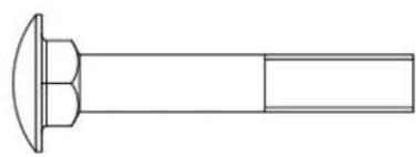
Technical line drawing of a mechanical component with a flanged top and rectangular shaft (no text or symbols)(17) Bolt M8x70 4 PCS
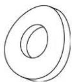
(14) Big Curve Washer ∅8
4 PCS
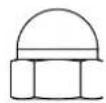
(30) Cap Nut M8 4 PCS
TOOLS
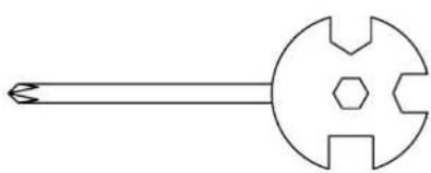
natural_image
Simple line drawing of a mechanical tool or knob with a circular head and hexagonal base (no text or symbols)Multi Hex Tool with Phillips Screwdriver S10-S13-S14-S15 IPcs
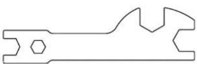
natural_image
Pure line drawing of a mechanical wrench (no text or symbols)natural_image
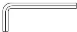
Simple L-shaped line drawing with no text, numbers, or symbolsAllen Wrench 1PCS
ASSEMBLY INSTRUCTIONS
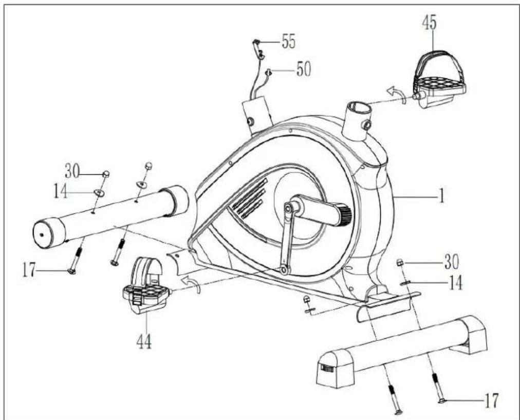
1. Front and Rear Stabilizers Installation
Position the Front Stabilizer (2) in front of the Main Frame (1) and align bolt holes.
Attach the Front Stabilizer (2) onto the front curve of the Main Frame (1) with two M8x70 Bolts (17) two ∅8 Big Curve Washers (14) and two M8 Cap Nuts (30).
Position the Rear Stabilizer (3) behind the Main Frame (1) and align bolt holes.
Attach the Rear Stabilizer (3) onto the rear curve of the Main Frame (1) with two M8x70 Bolts (17) two ∅8 Big Curve Washers (14) and two M8 Cap Nuts (30).
Foot Pedals Installation
The Cranks, Foot Pedals, Pedal Shafts and Pedal Straps are marked "R" for Right and "L" for Left.
Insert the pedal shaft of Left Foot Pedal (44) into threaded hole in the left Crank (37). Turn the pedal shaft by hand in the counter-clockwise direction until snug.
Note: DO NOT turn the pedal shaft in the clockwise direction, doing so will strip the threads.
Screwdriver provided Insert pedal shaft of Right Foot Pedal (45) into threaded hole in right Crank (38). Turn the pedal shaft by hand in the clockwise direction until snug.
2. Seat Post, Seat Post Cover and Seat Cushion Installation
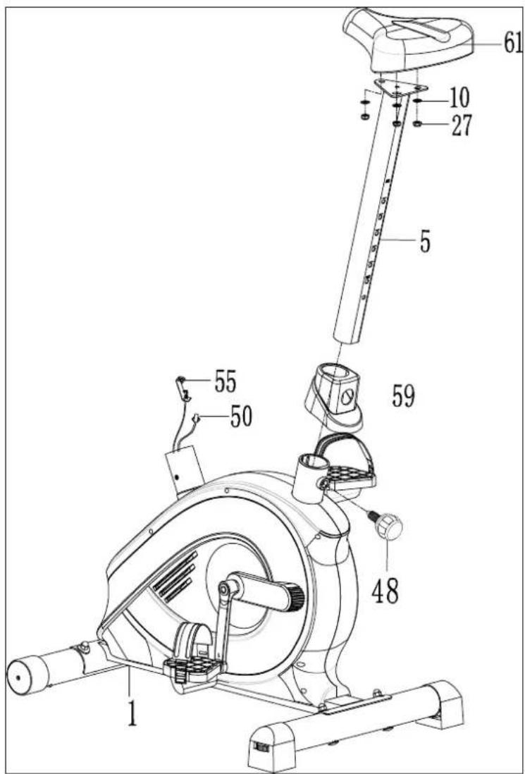
Slide the Seat Post Cover (59) onto the tube of the Main Frame (1).
Insert the Seat Post(5) into the Seat Post Bushing (53) on the tube of the Main Frame (1) and then attach the Seat Post Knob (48) onto the tube of the Main Frame (1) by turning it in a clockwise direction and lock the Seat Post (5) in the suitable position.
Remove three M8 Nylon Nuts (27) and three ∅16x∅8x1.5 Washers (10) from underside of the Seat Cushion (61).
Guide bolts on underside of the Seat Cushion (61) through holes on top of the Seat Post (5), attach with three M8 Nylon Nuts (27) and ∅16x∅8x1.5 Washers (10) that were removed.
3. Handlebar Post, Handlebar Post Cover, and Tension Control Knob Installation
Remove four M8x15 Bolts (19), four ∅20x∅8x2.0 Washers (14) from the Main Frame (1). Slide the Handlebar Post Cover (58) up to the Handlebar Post (7).
Insert the Tension Cable (55) through into the bottom hole of Handlebar Post (7) and pull it out from the square hole of Handlebar Post (7).
Connect the Sensor Wire (50) from the Main Frame (1) to the Extension Sensor Wire (62) from the Handlebar Post (7).
Insert the Handlebar Post (7) onto the tube of the Main Frame (1) and secure with four M8x15 Bolts (19), four ∅20x∅8x2.0 Washers (14) that were removed.
Slide the Handlebar Post Cover (58) down to the Handlebar Post (7).
Remove the M5x55 Bolt (40) and ∅5 Big Washer (41) from the Tension Control Knob (54). Put the cable end of resistance cable of Tension Control Knob (54) into the spring hook of Tension Cable (55) as shown in drawing A of figure 3.
Pull the resistance cable of Tension Control Knob (54) up and force it into the gap of metal bracket of Tension Cable (55) as shown in drawing B of figure 3.
Attach the Tension Control Knob (54) onto the Handlebar Post (7) with the M5x55 Bolt (40) and ∅5 Big Washer (41) that were removed.
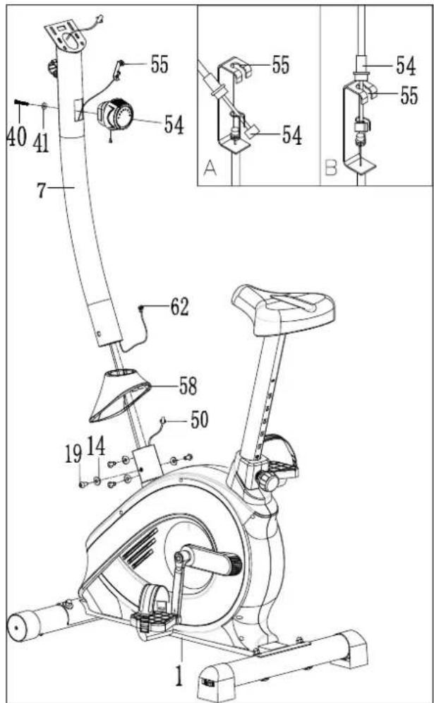
4. Handlebar Installation
Insert the Hand Pulse Sensor Wires (49) into the hole on the Handlebar Post (7) and then pull them out from the top end of the Handlebar Post (7).
Place the Handlebar (8) through clamp on the Handlebar Post (7) with hand pulse sensors facing the seat.
Hold the Handlebar (8) in desired position and fasten Clamp Cover (65), ∅12x20x1.5 Spacer (66), and Handlebar T-Knob (667) onto clamp.
Tighten the Handlebar T-Knob (67) after adjustment.
NOTE: Handlebar T-Knob should be tightly secured before using.
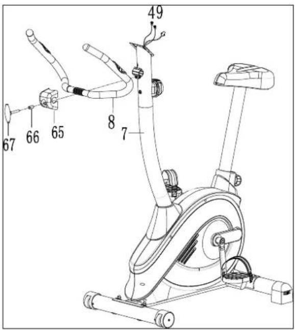
5. Computer Installation
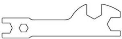
Remove four M5x10 Bolts (42) from the Computer (15). Remove bolts with the Multi Hex Tool with Phillips Screw driver provided.
Connect the Hand Pulse Sensor Wires (49) and Extension Sensor Wire (62) to the wires that come from the Computer (15).
Tuck wires into the Handlebar Post (7). Attach the Computer (15) onto the top end of the Handlebar Post (7) with four M5x10 Bolts (42) that were removed. Tighten bolts with the Multi Hex Tool with Phillips Screwdriver provided.
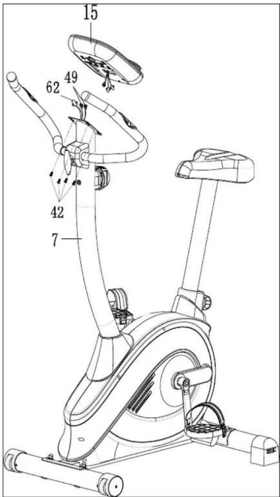
OVERVIEW DRAWING
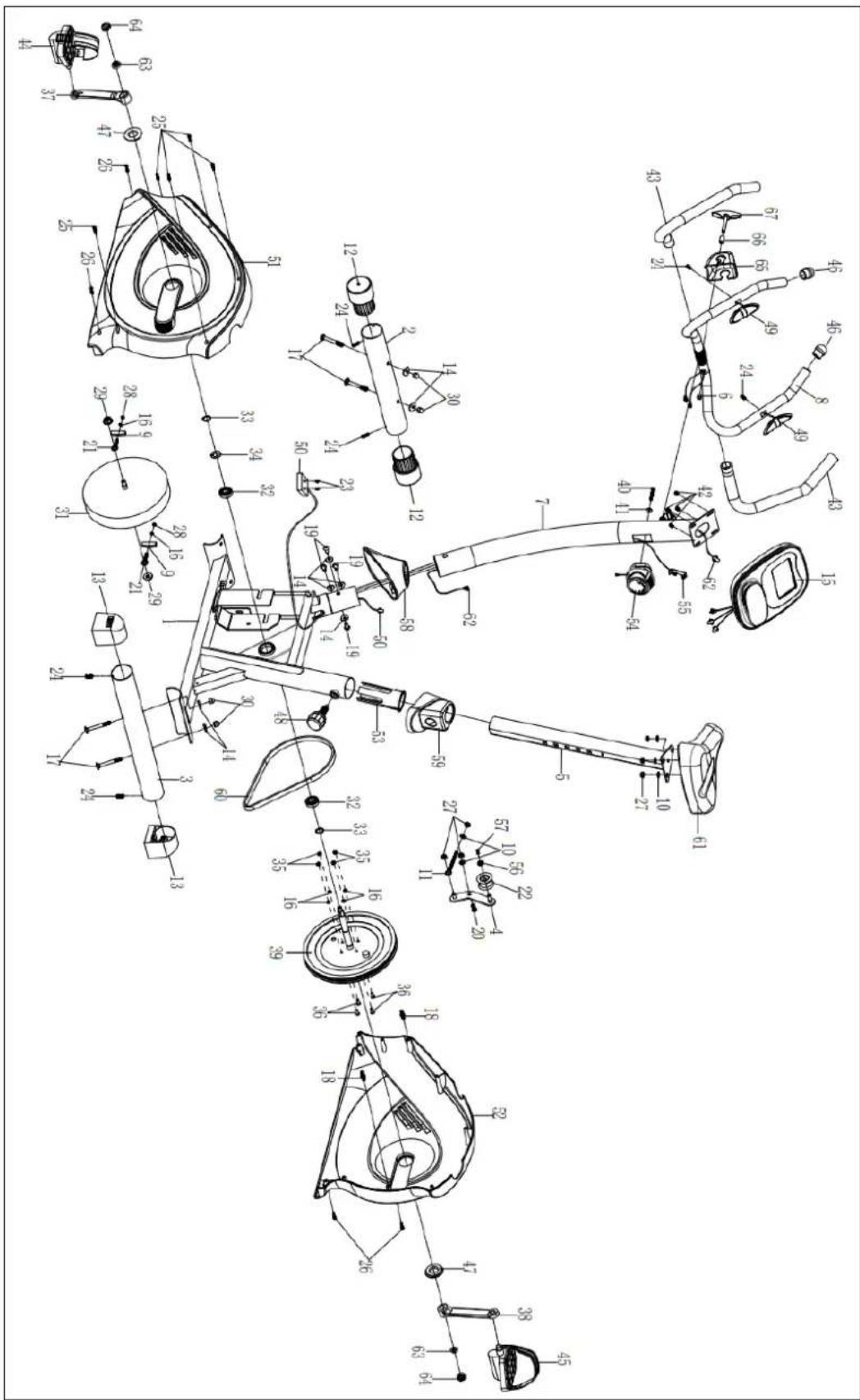
PARTS LIST
| No. | Description | Qty | No. | Description | Qty |
| 1 | Main Frame | 1 | 24 | Screw ST4.2×20 | 6 |
| 2 | Front Stabilizer | 1 | 25 | Screw ST4.2×25 | 5 |
| 3 | Rear Stabilizer | 1 | 26 | Screw ST4.2×25 | 4 |
| 4 | Idle Wheel Bracket | 1 | 27 | Nylon Nut M8 | 6 |
| 5 | Seat Post | 1 | 28 | Nut M6 | 2 |
| 6 | Wire plug | 1 | 29 | Hexagon Nut M10 | 2 |
| 7 | Handlebar Post | 1 | 30 | Cap Nut M8 | 4 |
| 8 | Handlebar | 1 | 31 | Flywheel | 1 |
| 9 | U Bracket | 2 | 32 | Bearing 6003 | 2 |
| 10 | Washer ∅16x∅8x1.5 | 5 | 33 | C-clip ∅17 | 2 |
| 11 | Eyebolt M8x85 | 1 | 34 | Wave washer ∅17 | 1 |
| 12 | End Cap For Front Stabilizer | 2 | 35 | Nut M6 | 4 |
| 13 | End Cap For Rear Stabilizer | 2 | 36 | Bolt M6x15 | 4 |
| 14 | Big Curve Washer ∅8 | 8 | 37 | Left crank | 1 |
| 15 | Computer | 1 | 38 | Right crank | 1 |
| 16 | Spring washer ∅6 | 6 | 39 | Belt Pulley | 1 |
| 17 | Bolt M8x70 | 4 | 40 | Bolt M5X55 | 1 |
| 18 | Plastic bolt ∅8x32 | 2 | 41 | Big Curve Washer ∅5 | 1 |
| 19 | Bolt M8x15 | 4 | 42 | Bolt M5X10 | 4 |
| 20 | Bolt M8x20 | 1 | 43 | Handlebar Foam Grip | 2 |
| 21 | Eyebolt M6x36 | 2 | 44 | Left Pedal YH-30X | 1 |
| 22 | Idle Wheel ∅10x∅35 | 1 | 45 | Right Pedal YH-30X | 1 |
| 23 | Screw ST2.9×12 | 2 | 46 | End Cap for Handlebar | 2 |
PARTS LIST
| No. | Description | Qty | No. | Description | Qty |
| 47 | Cover Cap | 2 | 58 | Handlebar Post Cover | 1 |
| 48 | Round Knob M16 | 1 | 59 | Seat Post Cover | 1 |
| 49 | Hand Pulse Sensor with Wire L=750mm | 2 | 60 | Belt | 1 |
| 50 | Sensor with Wire L=750mm | 1 | 61 | Seat Cushion | 1 |
| 51 | Left Chain Cover | 1 | 62 | Extension Sensor Wire (L=1000mm) | 1 |
| 52 | Right Chain Cover | 1 | 63 | Nut M10x1.25 | 2 |
| 53 | Seat Post Bushing | 1 | 64 | Cover for cranks | 2 |
| 54 | Tension Control Knob | 1 | 65 | Clamp Cover | 1 |
| 55 | Tension Cable | 1 | 66 | Spacer (∅12x20x1.5) | 1 |
| 56 | Washer ∅12x∅6x1.0 | 1 | 67 | Handlebar T-Knob (M8x55) | 1 |
| 57 | Bolt M6x10 | 1 |
EXERCISE MONITOR INSTRUCTION MANUAL
SPECIFICATIONS:
TIME----0:00—99:59 HOUR
SPEED----0.0—99.9 KM/H
DISTANCE----0.00—999.99 KM
MODE - Press to select functions.
SET-To set the values of time, distance and calories when not in scan mode.
RESET -Press to reset time, distance and calories.
KEY FUNCTION:
SCAN: STEP INTO AUTO SCAN MODE,SHOW EVERY FUNCTION IN TURN. IN THIS MODE, EACH
FUNCTION CAN NOT BE SET; HOLD THIS KEY, THE CPMPUTER WILL BE RESET, EACH FUNCTION WILL
RETURN ZERO EXCEPT TOTAL DIASTANCE FUNCTION.
TIEM: SHOW CURRENT TIME YOU EXERCISE, IN THE MODE, YOU CAN PRESS UP OR DOWN KEY TO
SET THE TIME YOU WILL EXERCISE.
SPEED: SHOW CURRENT SPEED YOU EXERCISE.
DIST: SHOW CURRENT DISTANCES YOU EXERCISE, YOU CAN PRESS UP OR DOWN KEY TO SET
THE DISTANCE YOU WILL EXERCISE.
CAL: SHOW CURRENT CALORIES YOU EXERCISE, YOU CAN PRESS UP OR DOWN KEY TO SET THE
CALORIES YOU WILL EXERCISE.
ODO: SHOW THE TOTAL DISTANCES YOU EXERCISE FROM THE COMPUTER WORK. THIS MODE
CAN NOT BE SET.
♥: STEP INTO THE PULSE TEST: PLACE THE PALMS OF YOUR HANDS ON BOTH OF THE CONTACT
PADS AN FOR 30 SECONDS, THEN THE COMPUTER WILL SHOW CURRENT HEART RATE TO YOU.
COMPUTER POWER ON, THE MONITOR WILL SHOW FULL SCREEN FOR 1 SECOND TO ENTER
THE SCAN MODE: IN THE SCAN MODE, IF NOT KEY OPERATION, IT WILL AUTO SCAN INTO EACH
MODE FOR EVERY 6 SECONDS. IF KEY OPERATION, IT WILL STEP INTO THE FUNTION.
WHEN EXERCISE, THE TIME SPEED CALORIE DISTANCE ODO FUNCTIONS WILL WORK,
CALCULATE THE VALUES OF EACH FUNCTION. WHEN YOU STOP, THE COMPUTER WILL STOP WORK,
THE TIME MODE WILL STOP FOR 4 SECONDS. IF THERE IS NOT SINGAL INPUT FOR 4 MINUTES, THE
COMPUTER WILL STEP INTO SLEEP MODE----THE SCREEN WILL POWER OFF UNTIL SINGAL INPUT
The upright bike can be cleaned with a soft cloth and mild detergent. Do not use abrasives or solvents on plastic parts. Please wipe your perspiration off the upright bike after each use. Be careful not get excessive moisture on the computer display panel as this might cause an electrical hazard or electronics to fail.
Please keep the upright bike, specially, the computer console, out of direct sunlight to prevent screen damage.
Please inspect all assembly bolts and pedals on the machine for proper tightness every week.
Storage
Store the upright bike in a clean and dry environment away from children.
TROUBLESHOOTING
PROBLEM
The upright bike wobbles when in use.
There is no display on the computer console.
There is no heart rate reading or heart rate reading or is erratic / inconsistent.
The upright bike makes a squeaking noise when in use.
SOLUTION
Turn the adjustable leveler on the rear stabilizer as needed to level the upright bike.
-
Remove the computer console and verify the wires that come from the computer console are properly connected to the wires that come from the handlebar post.
-
Check if the batteries are correctly positioned and battery springs are in proper contact with batteries.
-
The batteries in the computer console may be dead. Change to new batteries.
-
Make sure that the wire connections for the hand pulse sensors are secure.
-
To ensure the pulse readout is more precise, please always hold on to the handlebar grip sensors with two hands instead of just with one hand only when you try to test your heart rate figures.
-
Gripping the hand pulse sensors too tight. Try to maintain moderate pressure while holding onto the hand pulse sensors.
The bolts may be loose on the upright bike, please inspect the bolts and tighten the loose bolts.
REPLACE THE BATTERIES AN THE SAME TIME.
MAINTENANCE
Cleaning
The elliptical trainer can be cleaned with a soft cloth and mild detergent. Do not use abrasives or solvents on plastic parts. Please wipe your perspiration off the elliptical trainer after each use. Be careful not get excessive moisture on the computer display panel as this might cause an electrical hazard or electronics to fail.
Please keep the elliptical trainer, specially, the computer console, out of direct sunlight to prevent screen damage.
Please inspect all assembly bolts and pedals on the machine for proper tightness every week.
Storage
Store the elliptical trainer in a clean and dry environment away from children.
| PROBLEM | SOLUTION |
| The elliptical trainer wobbles when in use. | Turn the rear stabilizer end cap on the rear stabilizer as needed to level the elliptical trainer. |
| There is no display on the computer console. | 4. Remove the computer console and verify the wires that come from the computer console are properly connected to the wires that come from the front post.5. Check if the batteries are correctly positioned and battery springs are in proper contact with batteries.6. The batteries in the computer console may be dead. Change to new batteries. |
| There is no heart rate reading or heart rate reading or is erratic / inconsistent. | 4. Make sure that the wire connections for the hand pulse sensors are secure.5. To ensure the pulse readout is more precise, please always hold on to the handlebar grip sensors with two hands instead of just with one hand only when you try to test your heart rate figures.6. Gripping the hand pulse sensors too tight.Try to maintain moderate pressure while holding onto the hand pulse sensors. |
| The elliptical trainer makes a squeaking noise when in use. | The bolts may be loose on the elliptical trainer, please inspect the bolts and tighten the loose bolts. |
Information on warm-up
The Warm Up Phase
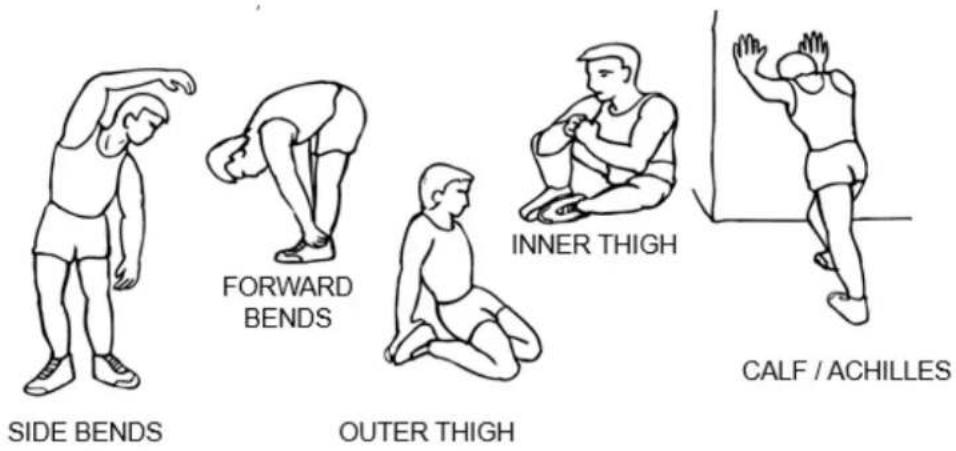
This stage helps get the blood flowing around the body and the muscles working properly. It will also reduce the risk of cramp and muscle injury. It is advisable to do a few stretching exercises as shown below. Each stretch should be held for approximately 30 seconds, do not force or jerk your muscles into a stretch - if it hurts, STOP.
The Cool Down Phase
This stage is to let your Cardio-vascular System and muscles wind down. This is a repeat of the warm up exercise e.g. reduce your tempo, continue for approximately 5 minutes. The stretching exercises should now be repeated, again remembering not to force or jerk your muscles into the stretch.
As you get fitter you may need to train longer and harder. It is advisable to train at least three times a week, and if possible space your workouts evenly throughout the week.
BEZPEČNOSTNÍ POKYNY
natural_image
Technical line drawing of a mechanical component with a flanged top and rectangular shaft (no text or symbols)(17) Šroub M8x70 4 KS
natural_image
Simple line drawing of a mechanical tool or knob with a circular head and hexagonal cutout (no text or symbols)natural_image
Pure line drawing of a mechanical wrench (no text or symbols)natural_image
Simple L-shaped metal angle bracket diagram (no text or symbols)Imbusový klíč 1ks
natural_image
Technical line drawing of a mechanical component with a flanged top and rectangular shaft (no text or symbols)(17) Šroub M8x70 4 KS
natural_image
Simple line drawing of a mechanical tool or knob with a circular head and hexagonal base (no text or symbols)Multi Hex Tool with Phillips Screwdriver S10-S13-S14-S15 IPcs
natural_image
Pure line drawing of a mechanical wrench (no text or symbols)natural_image
Simple L-shaped line drawing with no text, numbers, or symbolsAllen Wrench 1PCS
NÁVOD K MONTÁŽI
SEZNAM DÍLŮ
natural_image
Technical line drawing of a bolt head and shaft (no text or symbols)natural_image
Simple line drawing of a mechanical tool or knob with a central circular head and hexagonal base (no text or symbols)natural_image
Pure line drawing of a wrench tool without any text, numbers, or symbolsnatural_image
Simple L-shaped metal angle bracket diagram (no text or symbols)Inbusschlüssel 1 st.
MONTAGEANLEITUNG
TEILELISTE
EN: Marking the equipment with a symbol of a crossed-out waste container informs about prohibition of placing used electrical and electronic equipment with other household waste. According to the WEEE Directive on used electrical and electronic waste management, separate disposal methods must be applied for this type of equipment. A user, who intends to dispose this product, is required to deliver it to a collection point for used electrical and electronic equipment in order to contribute to reuse, recycling, or recovery and consequently, to protect the environment. To do this, contact the point where the device was purchased or local government officials. Hazardous components contained in the electronic equipment can cause long-lasting adverse changes in the environment, as well as have a harmful effect on human health.
- The Seller provides guarantee on behalf of the Guarantor within the territory of the Republic of Poland for the period of 24 months from the date of sale: electric power assisted booster 24 months, charger 6 months.
- The Guarantee will be recognised by the shop or service centre after the client provides:
- clearly and correctly filled-in guarantee card with the sale stamp and the seller's signature
- valid purchase confirmation for the equipment including the date of sale / bill, complained product.
- Possible defects and damages revealed during the guarantee period shall be remedied free of charge within not more than 21 days from the delivery of the product to the shop or service.
-
Should it be necessary to import some components, the guarantee term can be extended by the period required to import such part, however such period shall not be longer than 90 days.
-
The guarantee does not cover:
-
mechanical damages and subsequent defects,
- damages and defects resulting from incorrect storage and usage of the equipment against its purpose,
- incorrect assembly and maintenance,
-
damages and consumption of such elements as: cables, straps, rubber parts, pedals, sponge grips, wheels, bearings, etc.
-
The guarantee expires in the event of:
-
expiry of the validity term,
- self-repairs,
-
failure to follow the rules of correct operation.
-
The product handed over for repair should be complete and clean. If some parts are missing, the service is entitled to refuse to accept the product for repair. The service may refuse to accept a dirty product or clean in on the client's expense after the client's written permit.
-
The guarantee does not cover activities related to assembly, maintenance, which, according to the instruction, the user is obliged to perform themselves.
-
The Guarantor also informs that they offer post-guarantee service.
-
The product should be provided in its original packaging and should be secured for shipment.
-
To exercise the guarantee follow the procedure posted on the website: https://serwis.abisal.pl/ In case of non-conformity of the sold thing with the contract, the buyer is entitled by law to legal remedies from and at the expense of the seller. The guarantee does not affect such remedies.
THE EQUIPMENT IS NOT INTENDED FOR REHABILITATION AND THERAPY.
NOTES ON THE COURSE OF REPAIRS
| Item | Date of notificacion | Date of provision | Course of repairs | Signature of the recipient (shop, owner) |
ZÁRUČNÍ LIST
HMS-FITNESS.COM

IMPORTER: ABISAL SP. Z O.O., ul. Pyskowicka 17, 41-807 Zabrze, Polska
DISTRIBUTOR: ABISTORE SPORT S.R.O, U Cihelny 230/3, 74801 Hlučín, Česká
Republika abisal@abisal.pl www.abisal.pl
- ASSEMBLY INSTRUCTIONS
- Front and Rear Stabilizers Installation
- Foot Pedals Installation
- Seat Post, Seat Post Cover and Seat Cushion Installation
- Handlebar Post, Handlebar Post Cover, and Tension Control Knob Installation
- Handlebar Installation
- Computer Installation
- OVERVIEW DRAWING
- EXERCISE MONITOR INSTRUCTION MANUAL
- Storage
- TROUBLESHOOTING
- PROBLEM
- SOLUTION
- MAINTENANCE
- Cleaning
- Information on warm-up
- The Warm Up Phase
- The Cool Down Phase
- BEZPEČNOSTNÍ POKYNY
- NÁVOD K MONTÁŽI
- MONTAGEANLEITUNG
- ZÁRUČNÍ LIST
Brand : HMS Premium
Model : M5560
Category : Uncategorized