
M5812 - Uncategorized HMS Premium - Free user manual and instructions
Find the device manual for free M5812 HMS Premium in PDF.


| Product Type | Magnetic Exercise Bike |
| Model | M5812 |
| Brand | HMS Premium |
| Dimensions (Assembled) | 1090 x 560 x 1490 mm |
| Net Weight | 40 kg |
| Maximum User Weight | 150 kg |
| Flywheel Weight | 9 kg |
| Resistance Type | Magnetic |
| Resistance Levels | Varies (adjustable via console) |
| Power Supply | 240V AC adapter (included) |
| Display | LCD Console showing Time, Speed, RPM, Distance, Calories, Pulse, Watts |
| Training Programs | Manual, Beginner (4), Advance (4), Sporty (4), Cardio, Watt, User Program (U1-U4) |
| Bluetooth | Bluetooth 4.0 (compatible with iConsole+ app) |
| Body Fat Measurement | Yes (via handle pulse sensors) |
| Heart Rate Recovery Test | Yes |
| Pedals | Adjustable with toe cages |
| Seat Adjustment | Vertical and horizontal |
| Handlebar Adjustment | Tilt and height |
| Water Bottle Holder | Yes |
| Transport Wheels | Yes (2 wheels on front stabilizer) |
| Safety Class | EN ISO 20957-1 Class HA (home use) |
| Warranty | 24 months (12 months for electrical parts, 6 months for charger) |
| Maintenance | Wipe clean after use; check bolt tightness regularly |
Frequently Asked Questions - M5812 HMS Premium
User questions about M5812 HMS Premium
0 question about this device. Answer the ones you know or ask your own.
Ask a new question about this device
Download the instructions for your Uncategorized in PDF format for free! Find your manual M5812 - HMS Premium and take your electronic device back in hand. On this page are published all the documents necessary for the use of your device. M5812 by HMS Premium.
USER MANUAL M5812 HMS Premium
natural_image
Line drawing of a stationary exercise bike with adjustable arms and a digital display (no text or symbols)ROWER MAGNETYCZNY – MAGNETIC BIKE MAGNETICKÝ ROTOPED – MAGNETISCHER HEIMTRAINER
natural_image
Three vertical cylindrical objects with textured surfaces, no visible text or symbols26 M10×70×20-4
natural_image
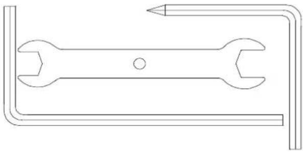
Pure technical line drawing of a wrench and pencil tool without any text or symbolsINFORMACJE TECHNICZNE
| MODEL | M5812 |
| WYMIARY PO ROZŁOŻENIU | 1090X560X1490mm |
| MAKSYMALNA WAGA UŻYTKOWNIKA | 150 KG |
| KOŁO ZAMACHOWE | 9 KG |
| OPÓR | MAGNETYCZNY |
| WAGA PRODUKTU | 40 KG |
Lista części
| NO. | NAZWA | SPECYFIKACJA | ILOŚĆ |
| 1 | RAMA GŁÓWNA | - | 1 |
| 2 | STABLIZATOR PRZEDNI | - | 1 |
| 3 | STABLIZATOR TYLNY | - | 1 |
| 4 | PODSTAWA SIEDZENIA | - | 1 |
| 5 | SIEDZENIE | - | 1 |
| 6 | KOLUMNA KIEROWNICY | - | 1 |
| 7 | UCHWYT | - | 1 |
| 8 | KONSOLA | - | 1 |
| 9 | PRZEWÓD KONSOLI | - | 1 |
| 10 | PRZEWÓD SILNIKA | - | 1 |
| 11 | PRZEWÓD POMIARU PULSU | - | 2 |
| 12 | WYLOT KONSOLI | - | 1 |
| 13 | OSŁONA PRZEDNIA | 89X73.5X35 | 1 |
| 14 | OSŁONA LEWA UCHWYTU | 176.5X53.2X117.5 | 1 |
| 15 | OSŁONA PRAWA UCHWYTU | 176.5X53.2X117.5 | 1 |
| 16 | OSŁONA SIEDZENIA LEWA | 195X28.5X118.5 | 1 |
| 17 | OSŁONA SIEDZENIA PRAWA | 195X31.5X118.5 | 1 |
| 18 | PEDAL LEWY (L) | - | 1 |
| 19 | PEDAL PRAWY (R) | - | 1 |
| 20 | UCHWYT NA BUTELKĘ | ∅93X150 | 1 |
| 21 | GAŁKA OBROTOWA T | M8X30 | 1 |
| 22 | PIERŚCIEŃ ZACISKOWY KIEROWNICY | - | 1 |
| 23 | GAŁKA | - | 1 |
| 24 | ŚRUBA SAMOGWINTUJĄCA | M5X10 | 4 |
| 25 | TULEJA | ∅25X∅19X60 | 1 |
| 26 | ŚRUBA | M10X70X20 | 1 |
| 27 | PODKŁADKA | ∅10 | 1 |
| 28 | PODKŁADKA | ∅10.5XR128Xt1.5 | 1 |
| 29 | ŚRUBA GWINTOWNA CAŁA | M4X6 | 6 |
| 30 | ŚRUBA | M8X20 | 5 |
| 31 | ŚRUBA Z PŁASKIM ŁBEM | M12X60 | 2 |
| 32 | ŚRUBA Z PEŁNYM GWINTEM | M4X16 | 6 |
| 33 | BLOKADA DO SIEDZENIA | 1 | |
| 34 | OSŁONA KORBY | ∅23X6XM22X | 2 |
| 35 | ŚRUBA Z PEŁNYM GWINTEM | 5/16-18UNC-1" | 2 |
| 36 | KORBA LEWA (L) | 1 | |
| 37 | KORBA PRAWA (R) | 1 | |
| 38 | PASEK | 440PJ6 | 1 |
| 39 | UCHWYT | ∅32Xt3.0X600 | 2 |
| 40 | OSŁONA SILNIKA LEWA (L) | 974.8X78.7X575.3 | 1 |
| 41 | OSŁONA SILNIKA PRAWA (R) | 974.8X83.2X575.3 | 1 |
| 42 | LINKA HAMULCOWA | 450X∅5X∅1.5XM6X1 | 1 |
| 43 | WTYCZKA | 240V | |
| 44 | CZUJNIK MAGNETYCZNY | 1 | |
| 45 | PRZEWÓD | 1 | |
| 46 | SILNIK MAGNETYCZNY | 1 | |
| 47 | ZAŚLEPKA | 45X90Xt1.5 | 4 |
| 48 | STOPKA | ∅49X22XM10X26 | 4 |
| 50 | KÓŁKA | ∅54.5X23.5 | 2 |
| 51 | ŚRUBA PEŁNA GWINTOWANA | M6X15 | 5 |
| 52 | ŁOŻYSKA KULKOWE | 6203-2RS | 3 |
| 53 | NAKRĘTKA | M5 | 2 |
| 54 | ŚRUBA | M5X60 | 1 |
| 55 | PODKŁADKA I SRUBA SAMOGWINTUJĄCA | ST4X12 | 1 |
| 56 | TULEJA SIEDZISKA | 115X90X45 | 1 |
| 57 | OŚ KORBY | ∅17X150 | 1 |
| 58 | PASEK NAPĘDOWY | ∅263X22 | 1 |
| 59 | NAKRĘTKA ZABEZPIECZAJĄCA | M8 | 10 |
| 60 | REGULACJA SIEDZENIA | 1 | |
| 61 | KOŁNIERZ DO WAŁU | 17 | 2 |
| 62 | KOŁNIERZ DO WAŁU | 12 | 2 |
| 63 | KOŁNIERZ DO WAŁU | 10 | 2 |
| 64 | KOŁO PASOWE | 38X22 | 1 |
| 65 | SPRĘŻYNA | 18X2.0X16 | 1 |
| 66 | SPRĘŻYNA NAPĘDOWA HAMULCA | 11.5X 1.2X13 | 1 |
| 67 | MAGNES | 30X25Xt12 | 10 |
| 68 | OŚ STEROWANIA MAGNETYCZNEGO | 12X50 | 1 |
| 69 | ŁOŻYSKA KULKOWE | 6300-2RS | 1 |
| 70 | PODKŁADKA PŁASKA | 34X 25Xt1.5 | 1 |
| 71 | ŁOŻYSKA KULKOWE | 6300-2RS | 1 |
| 72 | ŁOŻYSKO KULKOWE | 35X 17X16 | 1 |
| 73 | PASEK NAPĘDOWY | 30X64 | 1 |
| 74 | ŁOŻYSKA KULKOWE | 6300-2RS | 1 |
| 75 | OŚ KOŁA ZAMACHOWEGO | 10X114.5 | 1 |
| 76 | KOŁO ZAMACHOWE | 280 | 1 |
| 77 | ZATYCZKA | 20X40Xt1.5 | 1 |
| 78 | CZUJNIK POMIARU PULSU | 2 | |
| 79 | ŚRUBA SAMOGWINTUJĄCA | ST4X20 | 2 |
| 80 | ZATYCZKA | 28Xt1.5 | 2 |
| 81 | ŚRUBA SAMOGWINTUJĄCA | ST4X16 | 1 |
| 82 | MAGNEZ | 1 | |
| 83 | ŚRUBA | 9X 6.1 X27 | 1 |
| 84 | KOŁO | 1 | |
| 85 | MAGNES | 1 | |
| 86 | ŚRUBA PLASTIKOWA | 9X 6.1X27 | 6 |
| 87 | ŚRUBA SAMOGWINTUJĄCA | ST4X12 | 4 |
| 88 | ZAŚLEPKA | 15 | 2 |
| 89 | PODKŁADKA | 8 | 4 |
INSTRUKCJA MONTAŻU
Krok 1
Krok 4
Krok 6
Krok 8
Krok 9
Krok 10
natural_image
Line drawing of a stationary exercise bike with labeled components (no text or symbols present)Krok 11
natural_image
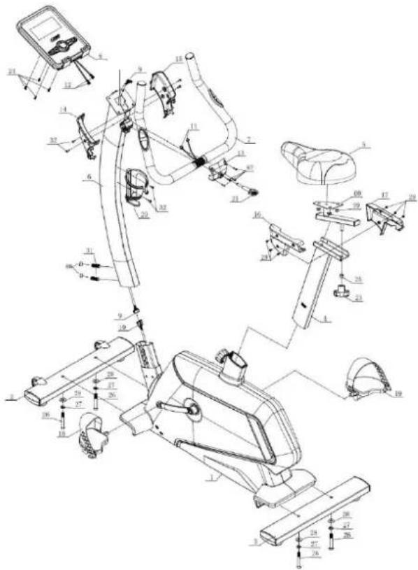
Line drawing of a stationary exercise bike with adjustable arm and seat (no text or symbols)Rysunek – montażowy
FUNKCJE PRZYCISKÓW:
RYS.1
Programy treningowe
RYS. 17
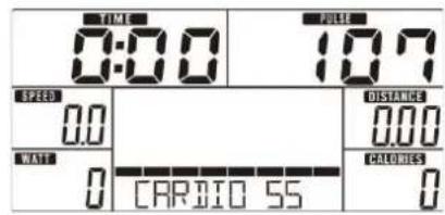
TRYB PROGRAMU UŻYTKOWNIKA
other
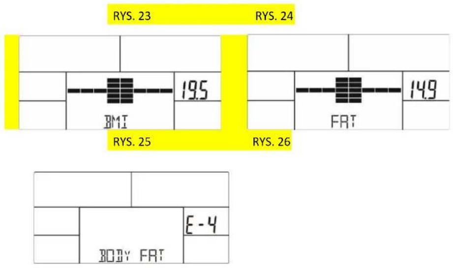
| Category | Value | | ------------ | ----- | | BMI | 19.5 | | FRT | 14.9 | | BODY FAT | E-4 |RYS. 27
Notatki:
natural_image
Silhouette of a person on a stationary bike, no text or symbols presentKrok 5.
Krok 6.
IMPORTANT SAFETY INFORMATION
This product has been designed for home use only and built for optimum safety. Please note the following safety precautions:
-
Before starting any exercise program you should consult your doctor to determine if you have any physical or health conditions that could create a risk to your health and safety, or prevent you from using the equipment properly. Your doctor's advice is essential if you are taking medication that affects your heart rate, blood pressure or cholesterol level. This is especially important for persons over the age of 35, pregnant women, or those with pre-existing health problems or balance impairments.
-
Before using this equipment to exercise, always do stretching exercises to properly warm up.
-
Be aware of your body's signals. Incorrect or excessive exercise can damage your health. Stop exercising if you experience any of the following symptoms: pain, tightness in your chest, irregular heartbeat, extreme shortness of breath, feeling light headed, dizzy or nauseous. If you do experience any of these conditions you should consult your doctor before continuing with exercise program. Injuries to health may result from incorrect or excessive training.
-
During exercises and after keep children and pets away from the equipment.
-
Use the equipment on a solid, flat level surface with a protective cover for your floor or carpet. Move all sharp objects.
-
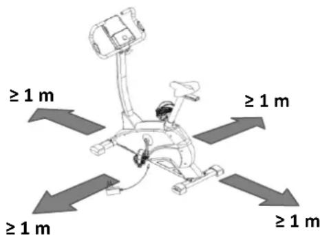
Free area shall be not less than 1 m greater than the training area in the directions from which the equipment is accessed. Free area must also include the area for emergency dismount. Where equipment is positioned adjacent to each other the value of the free area may be shared.
-
Before each use, visually inspect the unit including hardware and resistance bends.
-
Before using the equipment, check if the nuts, bolts and other bends are securely tightened.
-
Always use the equipment as indicated. If you find any defective components whilst assembling or checking the equipment, or if you hear any unusual noise coming from the equipment while using, stop. Do not use the equipment until the problem has been rectified.
-
Do not insert any object into any openings.
-
Be aware of all regulation and constructions parts which may disturb during exercises.
-
The safety level of the equipment can only be maintained if it is regularly examined for damage and/or wear and tear.
-
Wear suitable clothing whilst using the equipment. Avoid wearing loose clothing which may get caught in the equipment or that may restrict or prevent movement.
-
The equipment has been tested and certified according to EN ISO 20957-1 under class HA. It is not suitable for therapeutic use.
-
Care must be taken when lifting or moving the equipment so as not to injure your back. Always use proper lifting techniques and/or use assistance.
-
The equipment is designed for adult use only. Keep unsupervised children away from the equipment.
-
Assemble this unit as described in this manual. Use only parts from the set. Check all parts with the part list.
WARNING: READ ALL INSTRUCTIONS BEFORE USING ANY FITNESS EQUIPMENT. WE ASSUME NO RESPONSIBILITY FOR PERSONAL INJURY OR PROPERTY DAMAGE CAUSED BY OR THROUGH THE USE OF THIS PRODUCT
MAINTENANCE
Your unit has been carefully designed to require minimum maintenance. To ensure this, we recommend that you do the following: keep your unit clean by wiping sweat, dust or other residue off with a soft, clean cloth after each use. Always make sure that the bands are secure and show no signs of wear. Regularly check the tightness of nuts and bolts.
B30
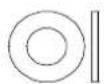
28 Φ10-4
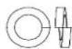
27 Φ10-4
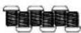
29 M4×6-6
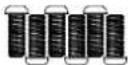
32 M4×16-6
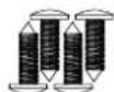
87 ST4×12-4
natural_image
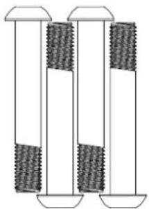
Three identical cylindrical components with textured surfaces, no text or symbols visible26 M10×70×20-4
natural_image
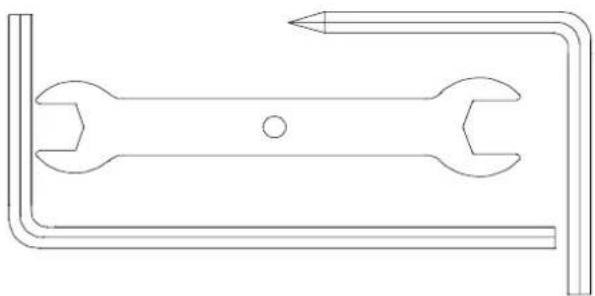
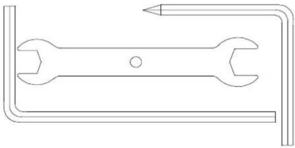
Line drawing of a double-ended wrench with a pointed tip, no text or symbols presentTECHNICAL INFORMATION
| MODEL | M5812 |
| DIMENSION | 1090X560X1490mm |
| MAX USER WEIGHT | 150 KG |
| FLYWHEEL | 9 KG |
| RESISTANCE | MAGNETYCZNY |
| NETT WEIGHT | 40 KG |
Part list
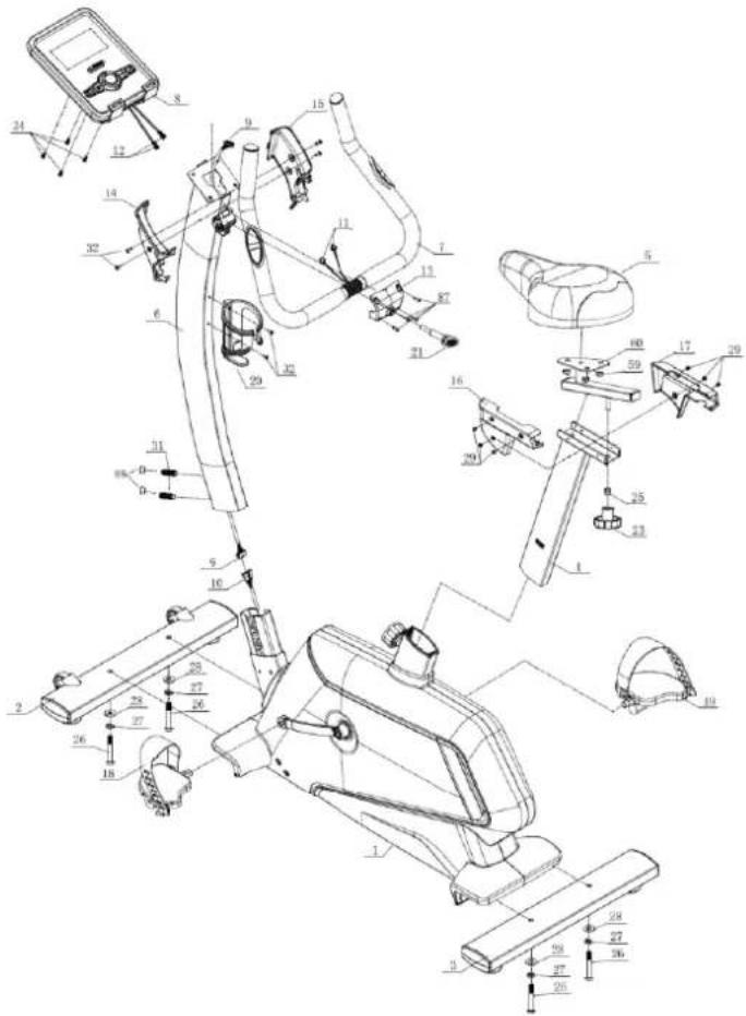
| NO. | NAME | DESCRIPTION | QTY |
| 1 | Main frame | 1 | |
| 2 | Front stabilizer | 1 | |
| 3 | Rear stabilizer | 1 | |
| 4 | Saddle post | 1 | |
| 5 | Saddle | 1 | |
| 6 | Upper Upright post | 1 | |
| 7 | Handlebars | 1 | |
| 8 | Console | 1 | |
| 9 | Console communication wire | 1 | |
| 10 | Motor communication wire | 1 | |
| 11 | Handle pulse connection wire | 2 | |
| 12 | Console outset | 1 | |
| 13 | Handlebar front | 89×73.5×35 | 1 |
| 14 | Handlebar cover-Left | 176.5×53.2×117.5 | 1 |
| 15 | Handlebar cover-Right | 176.5×53.2×117.5 | 1 |
| 16 | Saddle cover(L) | 195×28.5×111.8 | 1 |
| 17 | Saddle cover(R) | 195×31.5×111.8 | 1 |
| 18 | Pedal(L) | 1 | |
| 19 | Pedal(R) | 1 | |
| 20 | Bottle holder | Φ93×150 | 1 |
| 21 | T-shaped rotary knob | M8×30 | 1 |
| 22 | Handlebar clamp ring | 1 | |
| 23 | Handlebar rotary knob | 1 | |
| 24 | Philips C.K.S. self-tapping screw | M5×10 | 4 |
| 25 | Bushing tube | Φ25×Φ19×60 | 1 |
| 26 | Allen C.K.S. half thread screw | M10×70×20 | 4 |
| 27 | Spring washer | Φ10 | 4 |
| 28 | Curved washer | Φ10.5×R128×t1.5 | 4 |
| 29 | Philips pan head full thread screw | M4×6 | 6 |
| 30 | Allen C.K.S. full thread screw | M8×20 | 5 |
| 31 | Allen flat end set bolt | M12*60 | 2 |
| 32 | Phillips pan head full thread screw | M4×16 | 6 |
| 33 | Saddle locking piece | 1 | |
| 34 | Crank cover | 23 × 6 × M22 × P1.0 | 2 |
| 35 | Hex flange full thread screw | 5/16-18UNC-1" | 2 |
| 36 | Crank(L) | 1 | |
| 37 | Crank(R) | 1 | |
| 38 | Motor belt | 440PJ6 | 1 |
| 39 | Foam grip | 32 × t3.0 × 600 | 2 |
| 40 | Motor cover - left | 974.8×78.7×575.3 | 1 |
| 41 | Motor cover - right | 974.8×83.2×575.3 | 1 |
| 42 | Brake line | L- | 1 |
| 43 | Power adapter | 240 × 5 × 1.5 × M6 × 1 | 1 |
| 44 | Magnetic sensor | 1 | |
| 45 | Power communication wire | 1 | |
| 46 | Magnet motor | 1 | |
| 47 | End cap | 45×90×t1.5 | 4 |
| 48 | Feet pad | 49 × 22 × M10 × 26 | 4 |
| 49 | Allen C.K.S. hollow screw | 8 × 33 × M6 × 15 | 2 |
| 50 | Wheels | 54.5 × 23.5 | 2 |
| 51 | Allen C.K.S. full thread screw | M6×15 | 5 |
| 52 | Deep groove ball bearing | 6203-2RS | 3 |
| 53 | Hex nut | M5 | 2 |
| 54 | Hex full head screw | M5×60 | 1 |
| 55 | Philips washer head end-cutting and self-tapping bolt | ST4×12 | 1 |
| 56 | Saddle post bushing | 115×90×45 | 1 |
| 57 | Crank axis | 17 × 150 | 1 |
| 58 | Belt pulley | 263 × 22 | 1 |
| 59 | Hex locking nut | M8 | 10 |
| 60 | Saddle adjustment | 1 | |
| 61 | Circlip for shaft | 17 | 2 |
| 62 | Circlip for shaft | 12 | 2 |
| 63 | Circlip for shaft | 10 | 3 |
| 64 | Tension wheel | 38 × 22 | 1 |
| 65 | Tension spring | 18 × 2.0 × 16 | 1 |
| 66 | Brake tension spring | 11.5 × 1.2 × 13 | 1 |
| 67 | Square magnet | 30×25×t12 | 10 |
| 68 | Magnetic control axis | 12 × 50 | 1 |
| 69 | Deep groove ball bearing | 6300-2RS | 1 |
| 70 | Flat washer | 34 × 25 × t1.0 | 1 |
| 71 | Deep groove ball bearing | 6003-2RS | 1 |
| 72 | One-way kingpin ball bearing | 35× 17×16 | 1 |
| 73 | Small belt pulley | 30×64 | 1 |
| 74 | Deep groove ball bearing | 6000-2RS | 1 |
| 75 | Flywheel axis | 10×114.5 | 1 |
| 76 | Flywheel | 280 | 1 |
| 77 | Square pipe plug | 20×40× t1.5 | 1 |
| 78 | Handle pulse | 2 | |
| 79 | Philips C.K.S. self-tapping screw | ST4×20 | 2 |
| 80 | Round pipe plug | 28× t1.5 | 2 |
| 81 | Philips C.K.S. self-tapping screw | ST4×16 | 8 |
| 82 | Fixed magnet | 1 | |
| 83 | Rotary hand bolt | 9× M16× P1.5×83 | 1 |
| 84 | Fixed tension wheel | 1 | |
| 85 | Magnet | 1 | |
| 86 | Plastic bolt | 9× 6.1×27 | 6 |
| 87 | Philips C.K.S. self-tapping screw | ST4×12 | 4 |
| 88 | Hole plug | 15 | 2 |
| 89 | Spring washer | 8 | 4 |
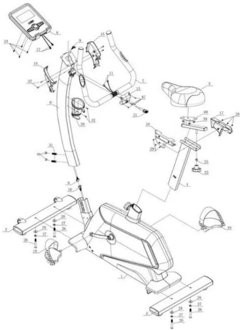
ASSEMBLY INSTRUCTIONS
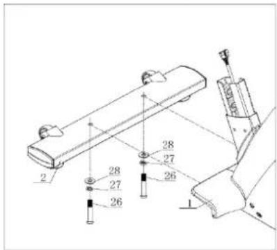
Step 1:
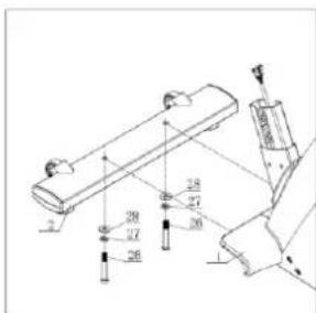
- Attach the front stabilizer (2) to the main frame (1) with curved washer(28), spring washer(27) and Allen C.K.S. half thread screw(26).
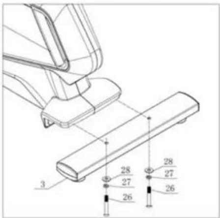
Step 2:
- Attach the rear stabilizer (3) to the main frame (1) with curved washer(28), spring washer(27) and Allen C.K.S. half thread screw(26).
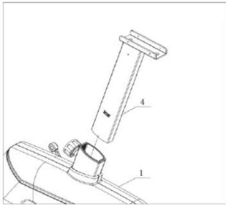
Step 3:
- Attach saddle post(4) to the main frame(1).
Step 4:
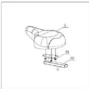
- assemble Saddle(5) on Saddle adjustment (60), lock with Hex locking nut (59)
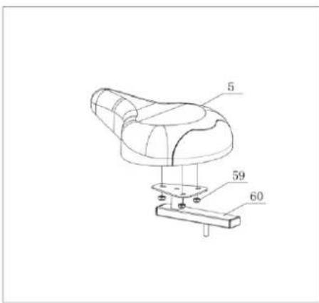
Step 5:
- Attach saddles(5) to the saddle post(4) with bushing tube (25) and handle knobs(23).
- Then attach saddle decoration cover (L)(16) and saddle decoration cover (R)(17) to saddle post(4) with Philips C.K.S. pan head full thread screw(29).
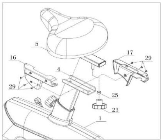
Step 6:
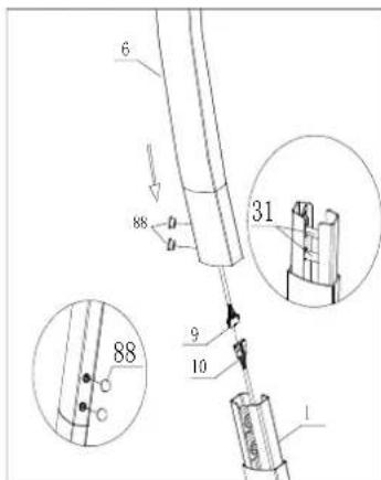
- First, Allen flat end set bolt(31) has been preinstalled on Main frame(1) inside, please don't lock (31) temporarily.
- Connect motor communication wire (10) and console communication wire(9).
Attach the upright post (6) to the main frame(1). Lock the Allen flat end set bolt (31) installed on the main frame, and cover the hole with hole plug (88) after the riser is fixed.
(Notice: the two screws of the upright post should be locked in turn until the riser is firmly locked. When finished tightening one screw, then start on the other screw in turn until tightened the upright post)
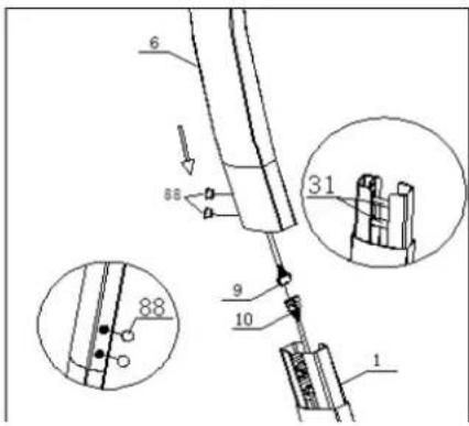
Step 7:
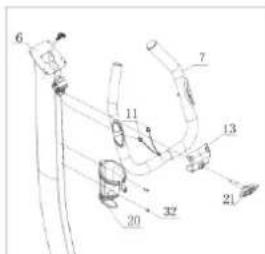
- Fixed the handlebar(7). Through handle pulse connection wire(11) out of the upright post(6). Then through the T shape knob(21) out of the handlebar front cover (13). Rotate inside. Notice: T shape knob don't rotatetightly.
- Attach bottle holder(20) to upper upright post(6) with Philips pan head full thread screw(32)
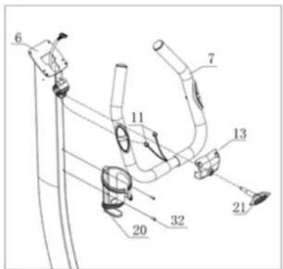
Step 8:
- Connect console communication wire(9) with back hole of the console. Connect handle pulse connection wire (11) with console outlet(12).
- Attach console(8) to upper upright post (6) with Philips C.K.S. full thread screw(24).
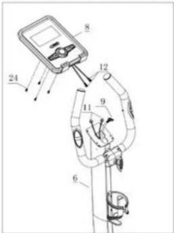
Step 9:
- Attach the handlebar cover – left (14) and right (15) to the upper upright post (6) with Phillips pan head full thread screw(32)
- Lock the handlebar front cover (13) with Phillips C.K.S. self-tapping screw(87).
- Adjust the Pulse tube to the suitable position. Rotate T shape knobtightly.
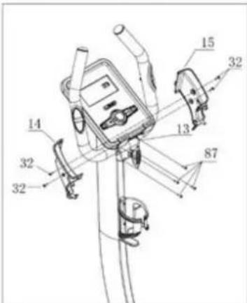
Step 10:
- Attach the Pedal left (18) and right (19) to main frame(1). Lock them.
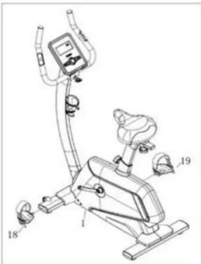
Step 11:
1. Insert the power pugs into power hole as shown below. Assembling finished.
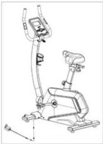
natural_image
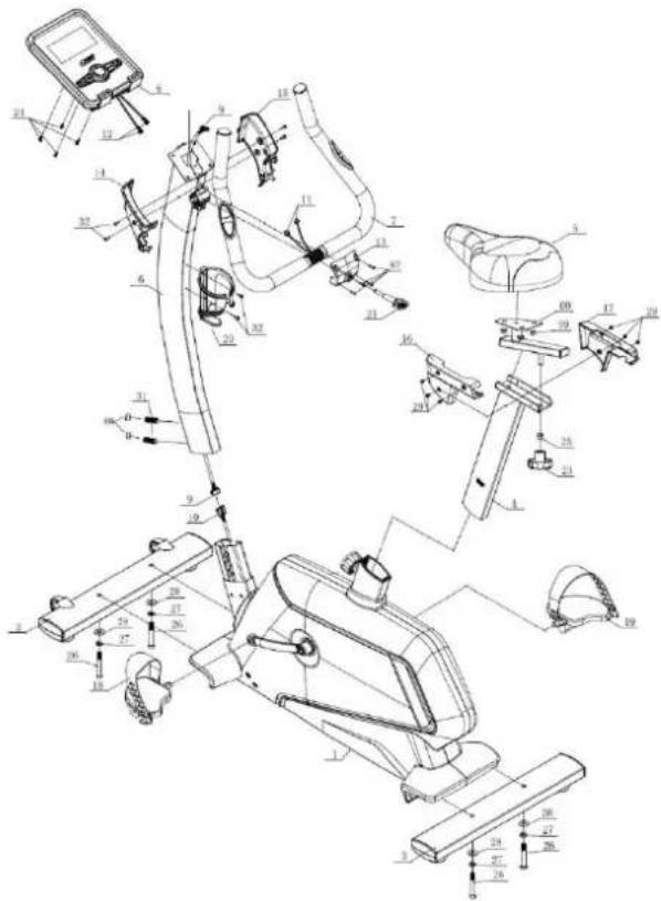
Line drawing of a stationary exercise bike with adjustable arm and legs (no text or symbols)Half-drawing for assembly
Button function:
| project | Description |
| Up (Encoder) | Increase resistanceSet the option |
| Down (Encoder) | Increase resistanceSet the option |
| Mode / Enter | Confirm Settings and selections. |
| Reset | Press this button for 2 seconds to restart the console and start from the userSettings screen.Return to the main page in set or pause mode. |
| Start/ Stop | Start or stop the movement. |
| Recovery | Test the heartbeat recovery status. |
| Body Fat | In pause mode, press this button to start testing body fat |
DISPLAY FUNCTIONS :
| project | Description |
| TIME | progressive increase – while without setting, Time start counting from 00:00, when reach the maximum 99:59, add 1 min every time.decrease progressively – while there is a setting, Time start counting down from setting number to 00:00increase or decrease 1 min every time, the range is within 00:00~99:00. |
| SPEED | Display current speed. The maximum is 99.9km/h or mph. |
| RPM | Display the RPM per minute, the displaying range is 0~15~999. |
| DISTANCE | Add up the total distance from 0.00 up to 99.99 km or mi.Users can press the UP/DOWN key to set the target distance in advance.Increase or decrease 1 km or mile at a time, ranging from 0.00 to 99.00 |
| CALORIES | Calculate the cumulative calories consumed during exercise, ranging from 0 to 9999 calories.(This data is only for comparison between different sports and should not be used for medical treatment.)Increase or decrease by 1CAL at a time, ranging from 0 to 9990 |
| PULSE | The user can set the target heartbeat value, ranging from 0-30 to 230;If the user's actual heartbeat exceeds the target heartbeat value during exercise, the buzzer will alarm. |
| WATTS | Displaying the current watts, ranging from 0 to 999. |
| MANUAL | Manual control mode |
| BEGINNER | 4 programs for option |
| ADVANCE | 4 programs for option |
| SPORTY | 4 programs for option |
| CARDIO | Exercise your cardio function |
| WATT PROGRAM | Watt constant training mode. |
| USER PROGRAM | Users create resistance level patterns |
OPERATION:
POWER ON
Plug in power supply, computer will power on with a long beep sound and display all segments on LCD for 2 seconds(FIG. 1).
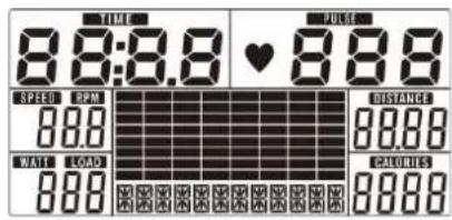
FIG. 1
Motion mode selection
Press UP or DOWN (Encoder) to select manual mode (FIG. 2) → beginner mode (FIG. 3) → advanced mode (FIG. 4) → athlete mode (FIG. 5) → cardiopulmonary exercise (FIG. 6) → WATT (FIG. 7) → user program (FIG. 8).
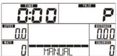
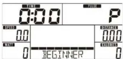
FIG. 2 FIG.3
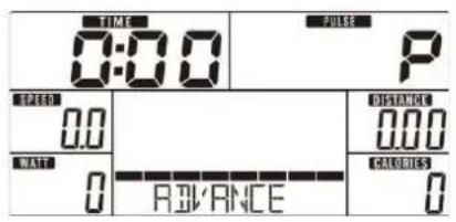
Press the "START" button on the home page to enter the manual mode and START the movement.
- Press UP or DOWN (Encoder) to select the motion program, select Manual, and press MODE/ENTER to confirm entry.
Press UP or DOWN (Encoder) to set time (Figure 9), distance (Figure 10), calories (Figure 11), heartbeat (Figure 12) and MODE/ENTER
-
Confirm the entry.
-
Press the START/STOP keys to START the movement. The user can also press UP or DOWN (Encoder) to adjust the resistance level during the movement. The resistance level is displayed in the watt window. If not adjusted for 3 seconds, the meter will switch to the watt value (Figure 13).
-
Press the START/STOP keys to START or STOP the movement. Press the RESET button to return to the main page.
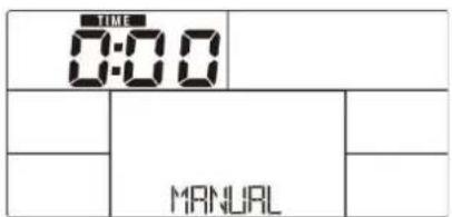
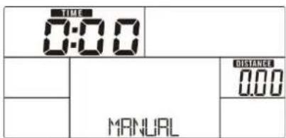
FIG. 9 FIG.10

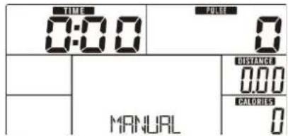
FIG.11 FIG.12
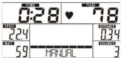
FIG.13
Beginner mode
- Press UP or DOWN ((Encoder) to select the exercise program, select Beginner Mode and press Mode/ENTER to confirm the entry.
- Press UP or DOWN (Encoder) to select beginner MODE 1 to 4 (Figure 14) and press MODE/ENTER to confirm entering.
- Press UP or DOWN (Encoder) to set the movement time.
- Press START/STOP to START the movement. The user can also press UP or DOWN (Encoder) to adjust the resistance level during the movement.
- Press the START/STOP keys to START or STOP the movement. Press the RESET button to return to the main page.
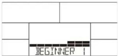
FIG. 14
Advanced mode
- Press UP or DOWN (Encoder) to select the motion program, select Advance Mode and press Mode/ENTER to confirm entering.
- Press UP or DOWN (Encoder) to select advanced modes 1 to 4 (Figure 15) and press MODE/ENTER to confirm entering.
- Press UP or DOWN (Encoder) to set the movement time..
- Press START/STOP to START the movement. The user can also press UP or DOWN (Encoder) to adjust the resistance level during the movement.
- Press the START/STOP keys to START or STOP the movement. Press the RESET button to return to the main page.
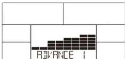
FIG. 15
Athlete mode
- Press UP or DOWN (Encoder) to select the sports program, select Sporty Mode and press Mode/ENTER to confirm entering.
- Press UP or DOWN (Encoder) to select player modes 1 to 4 (Figure 16) and press MODE/ENTER to confirm entering.
- Press UP or DOWN (Encoder) to set the movement time.
- Press START/STOP to START the movement. The user can also press UP or DOWN (Encoder) to adjust the resistance level during the movement.
- Press the START/STOP keys to START or STOP the movement. Press the RESET button to return to the main page.
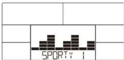
FIG. 16
Exercise cardio pattern
- Press UP or DOWN (Encoder) to select the motion program, select H.R.C and press MODE/ENTER to confirm entry.
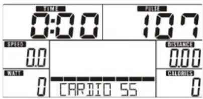
- Press UP or DOWN (Encoder) to set the age of exercise (Figure 17).
-
Press UP or DOWN (Encoder) to select 55% (Figure 18), 75%, 90% or TAG (target heart rate)(default: 100).
-
Press UP or DOWN (Encoder) to set the movement time.
- Press the START/STOP keys to START or STOP the movement. Press the RESET button to return to the main page.
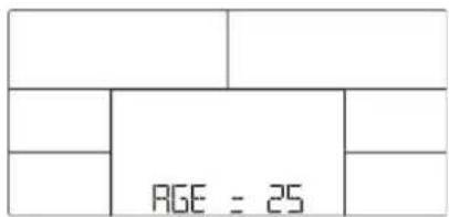
FIG. 17
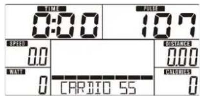
- Press UP or DOWN ((Encoder) to select the motion program, select WATT and press MODE/ENTER to confirm entering.
- Press UP or DOWN ((Encoder) to set the target WATT value (default: 120, Figure 19).
- Press UP or DOWN (Encoder) to set the movement time.
- Press START/STOP to START the movement. The user can also adjust the WATT level by pressing UP or DOWN (Encoder) during the movement.
- Press the START/STOP keys to START or STOP the movement. Press the RESET button to return to the main page.
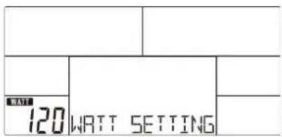
FIG. 19
User program mode
- Press UP or DOWN ((Encoder) to select the motion Program, select User Program Mode and press Mode/ENTER to confirm entering.
-
Press UP or DOWN (Encoder) to select U1-U4.
Press UP or DOWN (Encoder) to create the user profile (Figure 20). There are 20 items in total, and the user can adjust each resistance level. In the setup process -
The user can long press MODE/ENTER2 seconds to leave this program.
- Press UP or DOWN (Encoder) to set the movement time.
- Press the START/STOP keys to START the movement. The user can also adjust the WATT level by pressing UP or DOWN (Encoder) during the movement.
- Press the START/STOP keys to START or STOP the movement. Press the RESET button to return to the main page.
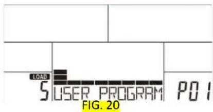
Recovery mode
After exercising for a period of time, keep both hands in hand grip or wear chest strap and press the RECOVERY button. All functions display stops except "TIME" starts counting down from 00:60 to 00:00 (Figure 21). Then the screen will show the heartbeat recovery status, F1, F2...F6 shows that F1 is the best and F6 is the worst (Figure 22). Users can keep exercising to improve the heartbeat recovery ability.(Press RECOVERY again to return to the main page)
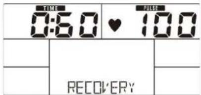
FIG. 21
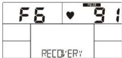
FIG. 22
Body fat model
- In pause mode, press the BODY FAT key to start the BODY FAT test
- Press UP or DOWN (Encoder) to select U1-U4.
- The spreadsheet will display the user's gender (Figure 23), height, weight and start the test.
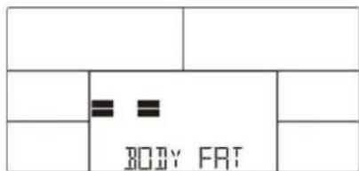
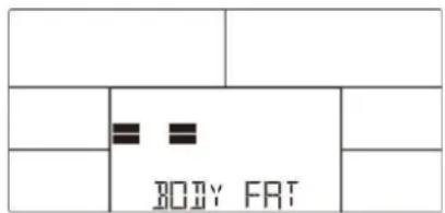
- During the test, the user must hold the handle with both hands. And the LCD will display "=" "=" ==" (Figure 24) for 8 seconds until the test is complete.
-
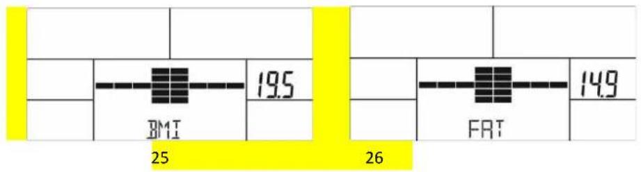
The LCD will display the body FAT recommendation symbol, BMI (Figure 25) and FAT % (Figure 26) for 30 seconds.
-
Error message:
*E-1 -- No heart rate signal was detected.
*E-4 -- Body fat percentage and body mass index below 5 or over 50(Figure 27).
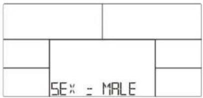
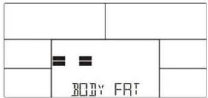
FIG 23
FIG 24
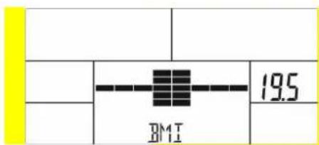
FIG 25
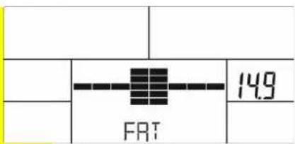
FIG 26
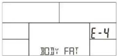
FIG 27
Notes:
- If no movement or heartbeat signal is input within 4 minutes, the electronic watch is put into hibernation mode. Press any key to wake up the electronic watch.
- If the display of the electronic meter is abnormal, remove the power supply and reinsert it.
- Problem with monitor or magnet. You should check whether monitor cable was connected well. If cable connected well, please replace monitor. If replace monitor is still not workable, please replace magnet motor.
System requirements:
Bluetooth 4.0
Android 4.3 or above
iOS 9 or above
Quick start
Step 1.
Download app iConsole+

Step 2.
Connect your device with Bluetooth 4.0
Step 3.
Open app

Step 4.
Start workout

natural_image
Silhouette of a person riding a stationary bike (no text or symbols)Step 5.
Customize training to your needs
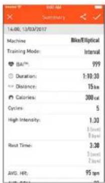
Step 6.
Chceck your workout summary and share
BEZPEČNOSTNÍ POKYNY
natural_image
Diagram of three identical cylindrical objects with textured surfaces, no text or symbols present
natural_image
Line drawing of a double-ended wrench with a pointed tip, no text or symbols presentSeznam částí
Krok 3:
Krok 4:
Krok 6:
Krok 9:
Krok 10:
natural_image
Line drawing of a stationary exercise bike with adjustable arm and legs (no text or symbols)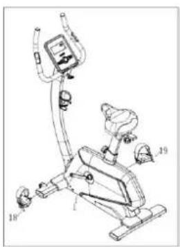
natural_image
Line drawing of a stationary exercise bike with labeled components (no text or symbols)Montážní nákres
Funkce tlačítek
Program H.R.C. – kardio
natural_image
Silhouette of a person on a stationary bike, no text or symbols presentKrok 5.
Krok 6.
natural_image
Three vertical cylindrical objects with textured surfaces, no visible text or symbols26 M10×70×20-4
natural_image
Pure technical line drawing of a wrench and pencil tool without any text or symbolsSchritt 4
Schritt 6
Schritt 8
Schritt 9
Schritt 10
Schritt 11
natural_image
Line drawing of a stationary exercise bike with adjustable arm and legs (no text or symbols)Einbauzeichnung
TASTENFUNKTIONEN:
17 18
Power-Modus
BENUTZERPROGRAMMMODUS
bar
| Category | BMI | FRT | |---|---|---| | Group 1 | 19.5 | 14.9 | | Group 2 | 25 | 26 |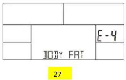
Anmerkungen
natural_image
Silhouette of a person on a stationary bike, no text or symbols presentKrok 5.
Krok 6.
EN: Marking the equipment with a symbol of a crossed-out waste container informs about prohibition of placing used electrical and electronic equipment with other household waste. According to the WEEE Directive on used electrical and electronic waste management, separate disposal methods must be applied for this type of equipment. A user, who intends to dispose this product, is required to deliver it to a collection point for used electrical and electronic equipment in order to contribute to reuse, recycling, or recovery and consequently, to protect the environment. To do this, contact the point where the device was purchased or local government officials. Hazardous components contained in the electronic equipment can cause long-lasting adverse changes in the environment, as well as have a harmful effect on human health.
-
The Seller provides guarantee on behalf of the Guarantor within the territory of the Republic of Poland for the period of 24 months from the date of sale: electric power assisted booster 24 months, charger 6 months.
-
The Guarantee will be recognised by the shop or service centre after the client provides:
- clearly and correctly filled-in guarantee card with the sale stamp and the seller's signature
- valid purchase confirmation for the equipment including the date of sale / bill, complained product.
-
Possible defects and damages revealed during the guarantee period shall be remedied free of charge within not more than 21 days from the delivery of the product to the shop or service.
-
Should it be necessary to import some components, the guarantee term can be extended by the period required to import such part, however such period shall not be longer than 90 days.
-
The guarantee does not cover:
- mechanical damages and subsequent defects,
- damages and defects resulting from incorrect storage and usage of the equipment against its purpose,
- incorrect assembly and maintenance,
- damages and consumption of such elements as: cables, straps, rubber parts, pedals, sponge grips, wheels, bearings, etc.
- The guarantee expires in the event of:
- expiry of the validity term,
- self-repairs,
- failure to follow the rules of correct operation.
-
The product handed over for repair should be complete and clean. If some parts are missing, the service is entitled to refuse to accept the product for repair. The service may refuse to accept a dirty product or clean in on the client's expense after the client's written permit.
-
The guarantee does not cover activities related to assembly, maintenance, which, according to the instruction, the user is obliged to perform themselves.
-
The Guarantor also informs that they offer post-guarantee service.
-
The product should be provided in its original packaging and should be secured for shipment.
-
To exercise the guarantee follow the procedure posted on the website: https://serwis.abisal.pl/
In case of non-conformity of the sold thing with the contract, the buyer is entitled by law to legal remedies from and at the expense of the seller. The guarantee does not affect such remedies.
THE EQUIPMENT IS NOT INTENDED FOR REHABILITATION AND THERAPY
NOTES ON THE COURSE OF REPAIRS
| Item | Date of notificacion | Date of provision | Course of repairs | Signature of the recipient (shop, owner) |
GARANTIEKARTE
Artikelname:
EAN-Code:
HMS-FITNESS.COM

IMPORTER: ABISAL SP. Z O.O., ul. Pyskowicka 17, 41-807 Zabrze, Polska
DISTRIBUTOR: ABISTORE SPORT S.R.O, U Cihelny 230/3, 74801 Hlučín, Česká Republika
abisal@abisal.pl www.abisal.pl
- ROWER MAGNETYCZNY – MAGNETIC BIKE MAGNETICKÝ ROTOPED – MAGNETISCHER HEIMTRAINER
- INSTRUKCJA MONTAŻU
- Krok 1
- Krok 4
- Krok 6
- Krok 8
- Krok 9
- Krok 10
- Krok 11
- TRYB PROGRAMU UŻYTKOWNIKA
- Notatki:
- Krok 5.
- Krok 6.
- IMPORTANT SAFETY INFORMATION
- MAINTENANCE
- ASSEMBLY INSTRUCTIONS
- Step 1:
- Step 2:
- Step 3:
- Step 4:
- Step 5:
- Step 6:
- Step 7:
- Step 8:
- Step 9:
- Step 10:
- OPERATION:
- POWER ON
- Advanced mode
- Athlete mode
- Exercise cardio pattern
- User program mode
- Recovery mode
- Body fat model
- Notes:
- System requirements:
- Quick start
- Step 1.
- Step 2.
- Step 3.
- Step 4.
- Step 5.
- Step 6.
- BEZPEČNOSTNÍ POKYNY
- Krok 3:
- Krok 4:
- Krok 6:
- Krok 9:
- Krok 10:
- Montážní nákres
- Program H.R.C. – kardio
- Schritt 4
- Schritt 6
- Schritt 8
- Schritt 9
- Schritt 10
- Schritt 11
- Power-Modus
- BENUTZERPROGRAMMMODUS
- Anmerkungen
- THE EQUIPMENT IS NOT INTENDED FOR REHABILITATION AND THERAPY
- GARANTIEKARTE
Brand : HMS Premium
Model : M5812
Category : Uncategorized