
eLink 100 - Audio/video extender Extron - Free user manual and instructions
Find the device manual for free eLink 100 Extron in PDF.


| Product Type | Wireless Audio/Video Extender |
| Brand | Extron |
| Model | eLink 100 |
| Power Supply | 5 VDC, 1.5 A minimum (Class 2 or LPS power adapter) |
| Power Consumption | 7.5 W maximum |
| Wireless Connectivity | IEEE 802.11a/b/g/n, 2.4 GHz and 5 GHz bands |
| Frequency Bands | 5.15-5.25 GHz (indoor), 5.25-5.35 GHz, 5.65-5.85 GHz |
| Antenna | Dipole, maximum gain 2 dBi |
| Approximate Range | 30 m indoors |
| Supported Video Resolution | Up to 1080p |
| Audio | Stereo transmission |
| Intended Use | Indoor only |
| Dimensions (L x W x H) | 100 x 60 x 20 mm |
| Weight | 150 g |
| Operating Temperature | 0 °C to 40 °C |
| Operating Humidity | 20% to 80% non-condensing |
| Maintenance and Cleaning | Clean with a soft, dry cloth. Do not use liquid or abrasive products. |
| Safety | Compliant with FCC Part 15, IC, CE. Maintain a minimum distance of 20 cm between the antenna and the body. |
| Supplied Accessories | Power adapter, antenna(s), documentation |
| Certifications | FCC Class B, IC, CE, NMB-003 |
Frequently Asked Questions - eLink 100 Extron
User questions about eLink 100 Extron
0 question about this device. Answer the ones you know or ask your own.
Ask a new question about this device
Download the instructions for your Audio/video extender in PDF format for free! Find your manual eLink 100 - Extron and take your electronic device back in hand. On this page are published all the documents necessary for the use of your device. eLink 100 by Extron.
USER MANUAL eLink 100 Extron
Safety Instructions • English

WARNING: This symbol, ,when used on the product, is intended to alert the user of the presence of uninsulated dangerous voltage within the product's enclosure that may present a risk of electric shock.

TENTION: This symbol, when used on the product, is intended to alert the user of important operating and maintenance (servicing) instructions in the literature provided with the equipment.
For information on safety guidelines, regulatory compliances, EMI/EMF compatibility, accessibility, and related topics, see the Extron Safety and Regulatory Compliance Guide, part number 68-290-01, on the Extron website, www.extron.com.
© 2014-2019 Extron Electronics. All rights reserved. www.extron.com
Trademarks
All trademarks mentioned in this guide are the properties of their respective owners. The following registered trademarks (®), registered service marks (SM), and trademarks (TM) are the property of RGB Systems, Inc. or Extron Electronics (see the current list of trademarks on the Terms of Use page at www.extron.com):
| Registered Trademarks ^(®) |
| Extron, Cable Cubby, ControlScript, CrossPoint, DTP, eBUS, EDID Manager, EDID Minder, Flat Field, FlexOS, Glitch Free. Global Configurator, Global Scripter, GlobalViewer, Hideaway, HyperLane, IP Intercom, IP Link, Key Minder, LinkLicense, LockIt, MediaLink, MediaPort, NetPA, PlenumVault, PoleVault, PowerCage, PURE3, Quantum, Show Me, SoundField, SpeedMount, SpeedSwitch, StudioStation, System INTEGRATOR, TeamWork, TouchLink, V-Lock, VideoLounge, VN-Matrix, VoiceLift, WallVault, WindoWall, XTP, XTP Systems, and ZipClip |
| Registered Service Mark ^(SM) : S3 Service Support Solutions |
| Trademarks ^(TM) |
| AAP, AFL (Accu-Rate Frame Lock), ADSP (Advanced Digital Sync Processing), Auto-Image, CableCover, CDRS (Class D Ripple Suppression), Codec Connect, DDSP (Digital Display Sync Processing), DMI (Dynamic Motion Interpolation), Driver Configurator, DSP Configurator, DSVP (Digital Sync Validation Processing), eLink, EQIP, Everlast, FastBite, FOX, FOXBOX, IP Intercom HelpDesk, MAAP, MicroDigital, Opti-Torque, PendantConnect, ProDSP, QS-FPC (QuickSwitch Front Panel Controller), Room Agent, Scope-Trigger, ShareLink, SIS, Simple Instruction Set, Skew-Free, SpeedNav, Triple-Action Switching, True4K, Vector ^TM 4K , WebShare, XTRA, and ZipCaddy |
FCC Class B Notice
NOTE: This device complies with part 15 of the FCC rules. Operation is subject to the following two conditions: (1) This device may not cause harmful interference, and (2) This device must accept any interference received, including interference that may cause undesired operation.
This equipment has been tested and found to comply with the limits for a Class B digital device, pursuant to part 15 of the FCC rules. These limits provide reasonable protection against harmful interference in a residential installation. This equipment generates, uses, and can radiate radio frequency energy and, if not installed and used in accordance with the instructions, may cause harmful interference to radio communications. There is no guarantee that interference will not occur. If this equipment does cause interference to radio or television reception, which can be determined by turning the equipment off and on, you are encouraged to try to correct the interference by one or more of the following measures:
- Reorient or relocate the receiving antenna.
- Increase the separation between the equipment and receiver.
- Connect the equipment into an outlet on a circuit different from that to which the receiver is connected.
- Consult the dealer or an experienced radio/TV technician for help.
In order to maintain compliance with FCC regulations, shielded cables must be used with this equipment. Operation with non-approved equipment or unshielded cables is likely to result in interference to radio and TV reception. The user is cautioned that changes and modifications made to the equipment without the approval of the manufacturer could void the user's authority to operate this equipment.
This Class B digital apparatus complies with Canadian ICES-003.
NOTE: For more information on safety guidelines, regulatory compliances, EMI/EMF compatibility, accessibility, and related topics see the “Extron Safety and Regulatory Compliance Guide” on the Extron website.
Safety Notices
USA—FCC and FAA
The FCC with its action in ET Docket 96-8 has adopted a safety standard for human exposure to radio frequency (RF) electromagnetic energy emitted by FCC certified equipment. The unit meets the Human Exposure limits found in OET Bulletin 65, supplement C, 2001, and ANSI/IEEE C95.1, 1992. Proper operation of this radio according to the instructions found in this manual will result in exposure substantially below the FCC's recommended limits.
ATTENTION: Due to the fact that the frequencies used by 802.11a, 802.11b, 802.11g, and 802.11n wireless LAN devices may not yet be harmonized in all countries, 802.11a, 802.11b, 802.11g, and 802.11n products are designed for use only in specific countries, and are not allowed to be operated in countries other than those of designated use.
As a user of these products, you are responsible for ensuring that the products are used only in the countries for which they were intended and for verifying that they are configured with the correct selection of frequency and channel for the country of use. Any deviation from the permissible power and frequency settings for the country of use is an infringement of national law and may be punished as such.
FCC Radio Frequency Interference Requirements
This device is restricted to indoor use due to its operation in the 5.15 to 5.25 GHz frequency range. FCC requires this product to be used indoors for the frequency range 5.15 to 5.25 GHz to reduce the potential for harmful interference to co-channel Mobile Satellite systems. High power radars are allocated as primary users of the 5.25 to 5.35 GHz and 5.65 to 5.85 GHz bands.
USA—Federal Communications Commission (FCC)
NOTE: The radiated output power of the wireless network device is far below the FCC radio frequency exposure limits. Nevertheless, the unit should be used in such a manner that the potential for human contact during normal operation is minimized. To avoid the possibility of exceeding the FCC radio frequency exposure limits, you should keep a distance of at least 20 cm between you (or any other person in the vicinity) and the antenna that is built into the unit. Details of the authorized configurations can be found at http://www.fcc.gov/ by entering the FCC ID number on the device.
Security IC Compliance
Canada, Industry Canada (IC) Notices
This Class B digital apparatus complies with Canadian ICES-003 and RSS-210.
ATTENTION:
- When using IEEE 802.11a wireless LAN, this product is restricted to indoor use due to its operation in the 5.15 to 5.25 GHz frequency range. Industry Canada requires this product to be used indoors for the frequency range of 5.15 GHz to 5.25 GHz to reduce the potential for harmful interference to co-channel mobile satellite systems. High power radar is allocated as the primary user of the 5.25 to 5.35 GHz and 5.65 to 5.85 GHz bands. These radar stations can cause interference with and/or damage to this device.
- The maximum allowed antenna gain for use with this device is 6dBi in order to comply with the E.I.R.P limit for the 5.25 to 5.35 and 5.725 to 5.85 GHz frequency range in point-to-point operation.
This device complies with Industry Canada's licence-exempt RSSs. Operation is subject to the following two conditions: (1) this device may not cause interference, and (2) this device must accept any interference, including interference that may cause undesired operation of the device.
Radio Frequency (RF) Exposure Information
To prevent radio interference to the licensed service, this device is intended to be operated indoors and away from windows to provide maximum shielding. Equipment (or its transmit antenna) that is installed outdoors is subject to licensing.
The radiated output power of the Extron Wireless Device is below the Industry Canada (IC) radio frequency exposure limits. The Extron Wireless Device should be used in such a manner such that the potential for human contact during normal operation is minimized.
Extron Unit IC ID: IC: 10862A-EXT60150801
IC Antenna Statement
Under Industry Canada regulations, this radio transmitter may only operate using an antenna of a type and maximum (or lesser) gain approved for the transmitter by Industry Canada. To reduce potential radio interference to other users, the antenna type and its gain should be so chosen that the equivalent isotropically radiated power (e.i.r.p.) is not more than that necessary for successful communication.
This radio transmitter (IC:10862A-EXT60150801) has been approved by Industry Canada to operate with the antenna types listed below with the maximum permissible gain and required antenna impedance for each antenna type indicated. Antenna types not included in this list, having a gain greater than the maximum gain indicated for that type, are strictly prohibited for use with this device.
Type: Dipole
Maximum Peak Gain: 2 dBi
Impedance: 50 Ohm
European Union
The low band 5.15-5.35 GHz is for indoor use only.
USA—Federal Communications Commission (FCC)
Conventions Used in this Guide
Notifications
The following notifications are used in this guide:
CAUTION: Risk of minor personal injury.
NOTE: A note draws attention to important information.
Specifications Availability
Product specifications are available on the Extron website, www.extron.com.
Contents
Introduction.... 1
About this Guide....1
About the eLink 100 Transmitter and Receiver....1
Features 2
Application Diagram 3
Installation....4
Before Getting Started....4
Front and Side Panel Features and Connections....5
Transmitter Connections 5
Receiver Connections......6
Installing the Plug on the Power Supply 7
The eLink 100 On-Screen Display....8
Top Panel Features and Functions 8
Transmitter Buttons and LEDs 8
Receiver Buttons and LEDs 9
Operation....10
Operating Modes....10
Registering the Transmitter with the Receiver....10
Registering Using the Remote Control ...... 10
Registering Using the Register Buttons......11
Registering an Additional Receiver....11
Using the Remote Control and the OSD Menus....12
Remote Control Buttons 12
Using the Setup Menu....13
Reference Information 15
Mounting the Transmitter and Receiver......15
Best Practices for eLink 100 Mounting Locations....17
Resolutions and Rates....18
Operating Frequencies 19
Troubleshooting....20
Introduction
- About this Guide
- About the eLink 100 Transmitter and Receiver
- Features
• Application Diagram
About this Guide
This guide describes how to install, operate, and configure the Extron eLink 100 wireless extender for High Definition Multimedia Interface (HDMI) signals. The eLink 100 extender consists of the eLink 100 T transmitter and the eLink 100 R receiver (sold separately).
About the eLink 100 Transmitter and Receiver
The eLink 100 transmitter and receiver pair uses multi-input and multi-output (MIMO) wireless communication technology to transmit HDMI video and multi-channel embedded audio. This HDCP-compliant extender can send computer video resolutions up to 1920x1080, including HDTV 1080p @ 60 Hz, with less than 1 ms required to process the video signal (latency). AES-128 encryption provides a secure link to send signals up to 100 feet (30 meters).
The eLink 100 T transmitter uses the 5 GHz spectrum to transmit signals. In addition to point-to-point applications, one transmitter can be linked with up to four eLink 100 R receivers, allowing a single source such as a digital signage player to support multiple displays.
The transmitter and receiver are wirelessly compatible only with each other, but they can wirelessly extend any Extron product that has HDMI connectivity, including switchers and scalers. The transmitter can be connected to any Extron HDMI output with a signal up to 1080p @ 60 Hz. The receiver can be connected to any Extron HDMI input.
NOTE: If using the eLink 100 as an extender to a switcher output, select a switcher with an integrated scaler or signal processor for fastest switch times (see www.extron.com for switcher part numbers).
The eLink 100 is ideal for use in professional AV environments such as presentation spaces, rental and staging, and digital signage.
Features
- Input — HDMI connector on eLink 100 T transmitter
Output — HDMI connector on eLink 100 R receiver
• Transmits HDMI video and multi-channel audio signals wirelessly up to 100 feet (30 meters) in professional AV environments. - Transmission through common obstacles — The eLink 100 wireless extender works in the 5 GHz spectrum to allow for broad coverage and transmission through walls and furniture. Line-of-sight is not required but can maximize range.
- Resolutions and rates — Supports computer video up to 1920x1080, including HDTV 1080p @ 60 Hz (see the Resolutions and Rates table on page 18).
- On-screen display (OSD) — The OSD provides an interface for simplified setup and configuration.
- IR remote control — The eLink IR remote control, included with the receiver, enables use of the OSD on the output screen for configuration and setup.
- Power supplies — Each unit includes an external 5 VDC power supply, which accepts 100 to 240 VAC, 50-60 Hz input. A DC-to-USB adapter is also provided with the receiver, enabling the power supply to power the receiver through its USB port.
- AES 128 encryption — Supports Advanced Encryption Standard (AES) 128 data encryption standard.
- HDMI features — Supported HDMI specification features include data rates up to 6.75 Gbps, Deep Color up to 12-bit, 3D, and multi-channel audio formats.
- HDCP compliant
- Ultra-low latency — Less than one millisecond of latency in transmission of video and audio signals
• Dynamic Frequency Selection (DFS) — - Actively monitors the radio frequency (RF) spectrum to select the most appropriate frequencies, and prevents interference from other devices operating in the spectrum.
- Takes advantage of DFS frequencies that are reserved for radar and weather purposes (see the Operating Frequencies table on page 19 for more information).
- Embedded audio — Compatible with a broad range of multi-channel audio signals, providing reliable operation with HDMI devices and surround sound systems.
- MIMO (multi-input and multi-output) — MIMO technology ensures that wireless connections are stable and function in environments with multipath signals.
- Wireless transmission to as many as four receivers — The transmitter can support up to four receivers, allowing a single source such as a digital signage player to support multiple displays.
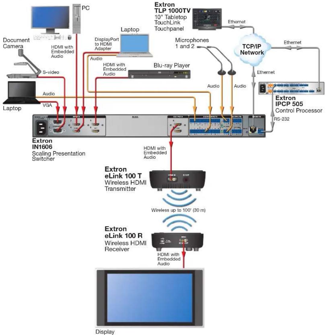
Application Diagram
flowchart
graph TD
    A["PC"] -->|S-video| B["Laptop"]
    B -->|Audio| C["Extron IN1606 Scaling Presentation Switcher"]
    C -->|VGA| D["Extron eLink 100 T Wireless HDMI Transmitter"]
    D -->|HDMI with Embedded Audio| E["Extron eLink 100 R Wireless HDMI Receiver"]
    E -->|HDMI with Embedded Audio| F["Extron IPCP 505 Control Processor RS-232"]
    F -->|Ethernet| G["TCP/IP Network"]
    G -->|Ethernet| H["Document Camera"]
    G -->|Ethernet| I["Display"]
    C --> J["Laptop"]
    J --> K["Extron TLP 1000TV 10" Tabletop TouchLink Touchpanel"]
    K --> L["Laptop"]
    K --> M["Microphones 1 and 2"]
    K --> N["Audio"]
    K --> O["Audio"]
    style A fill:#f9f,stroke:#333
    style B fill:#ccf,stroke:#333
    style C fill:#cfc,stroke:#333
    style D fill:#fcc,stroke:#333
    style E fill:#cff,stroke:#333
    style F fill:#ffc,stroke:#333
    style G fill:#fcf,stroke:#333
    style H fill:#cff,stroke:#333
    style I fill:#ffc,stroke:#333
Figure 1. Example of an eLink 100 Transmitter and Receiver Application
Installation
This section provides instructions for installing the eLink 100 extender, including:
• Before Getting Started
• Front and Side Panel Features and Connections
• Installing the Plug on the Power Supply
• The eLink 100 On-Screen Display
• Top Panel Features and Functions
Before Getting Started
If mounting is required before cabling and setting up the eLink 100 units, see Mounting the Transmitter and Receiver on page 15 for mounting instructions.
ATTENTION:
NOTE: For best performance:
- Ensure that the installation location is suitable for good signal transmission.
- For optimal signal range, avoid obstructions, such as walls, furniture or rack enclosures, between the transmitter and receiver locations. Denser wall materials can cause signal reduction.
• Maximum transmission distance is 100 feet (30 meters) with a clear line-of-sight. - Up to four transmitter units can operate in the same room or environment. If a maximum of four transmitters is reached, the next group of units should be separated to prevent interference (see Best Practices for eLink 100 Mounting Locations on page 17).
- Maintain a distance of at least 6.5 feet (2 meters) between multiple eLink transmitters or multiple eLink receivers. Be mindful of units located beyond walls in adjacent rooms.
- Maintain a distance of at least 6.5 feet (2 meters) between the eLink 100 units and other 5 GHz RF devices. RF products can cause interference or traffic in the 5 GHz frequency band. Monitor the 5 GHz frequency band and plan systems to avoid traffic.
- Do not block the eLink 100 air ventilation openings and ensure proper air ventilation around the units.
- Be careful when handling the eLink 100 units as they become hot during operation.
- Do not install above ceiling tiles. The eLink 100 is not UL Listed for use in plenum air handling spaces.
Front and Side Panel Features and Connections
Transmitter Connections
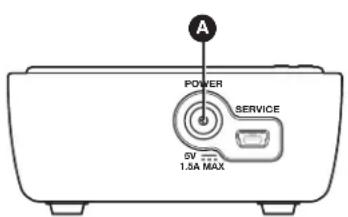
Front Panel
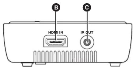
Side Panel
Figure 2. eLink 100 T Transmitter Side Panels
Power input connector — Plug the external 5 VDC power supply into this 5 V jack to power the transmitter.
NOTES:
- Use only the power supply provided by Extron (see the Attention on page 7 for important information).
- The USB mini-B port to the right of this connector is reserved for use by Extron service personnel.
- See Installing the Plug on the Power Supply on page 7 if a different power supply plug is needed for your location.
B HDMI In connector — Connect an HDMI cable between this port and the HDMI output port of the digital video source device.
C IR Out connector — (Optional) Connect the tip-ring-sleeve end of the provided IR emitter to this IR Out connector. Use the included double-sided adhesive tape to attach the head of the IR emitter directly over the IR receiver window of the source device.
IR remote signals are passed from the receiver to the IR Out connector on the transmitter. This feature allows the user to point the remote control toward the receiver (by the display) instead of the source device, should the source device be in a different location.
NOTE: This feature also applies to applications with multiple receivers (see Operating Modes on page 10 for details on applications with more than one receiver). IR remote signals are passed from any of the registered receivers to the transmitter.
Receiver Connections
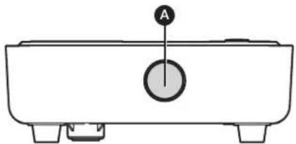
natural_image
Simple line drawing of a rectangular container with a circular button labeled 'A' (no text or symbols beyond the label)Front Panel
Back Panel
Figure 3. eLink 100 R Receiver Side Panel
A IR sensor — Receives IR commands from the included IR remote control unit and the IR remote of the source device.
NOTES:
- The IR sensor is compatible only with 38 kHz IR carrier frequency. See the specifications for the IR remote of the source device or contact the device manufacturer to verify the compatibility of the IR remote frequency.
- Make sure that the receiver IR sensor faces forward if using a source device IR remote to pass signals back to the transmitter. Wall mounting or concealing the receiver causes the IR sensor to be unreachable.
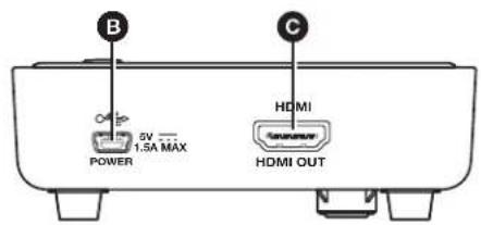
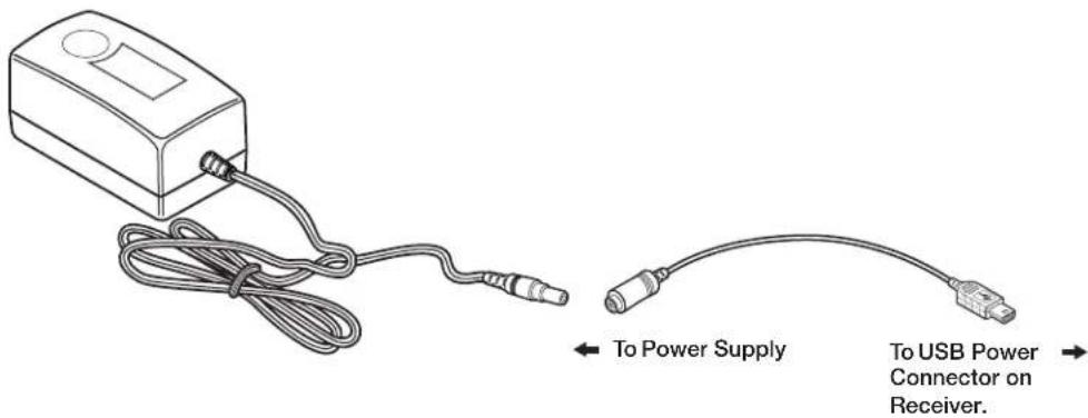
B USB Power connector — Connect the USB end of the provided 5 V jack-to-USB adapter to this USB mini-B connector. Connect the other end of the adapter to the provided 5 VDC power supply.
NOTE: Use only the power supply provided by Extron (see the Attention on the next page for important information).
© HDMI Out connector — Connect an HDMI cable between this port and the HDMI input connector of the display device.
ATTENTION:
- Unless otherwise stated, the AC/DC adapters are not suitable for use in air handling spaces or in wall cavities.
- The installation must always be in accordance with the applicable provisions of National Electrical Code ANSI/NFPA 70, article 725 and the Canadian Electrical Code part 1, section 16. The power supply shall not be permanently fixed to a building structure or similar structure.
Installing the Plug on the Power Supply
Each eLink 100 power supply kit contains a set of four plugs for use in different outlet types:
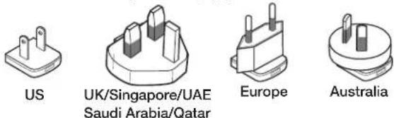
Figure 4. Included Power Supply Plugs
Select the appropriate plug for your location and follow the instructions below to install it on the power supply.
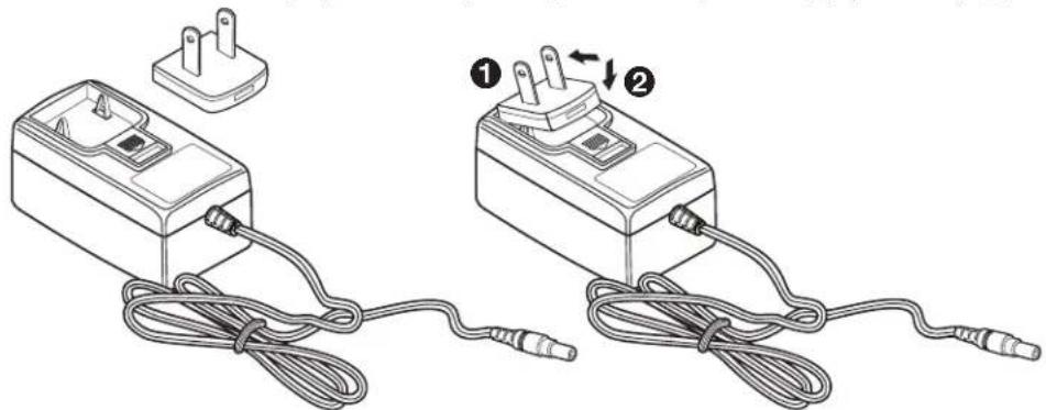
- Slide the tab at the top of the power plug under the top edge of the recess in the power supply (see figure 5, ①).
- Press down on the plug until it snaps into place in the power supply recess (②).
natural_image
Two electrical components connected by wires, one with a plug and the other with a plug and cable (no text or symbols visible)Figure 5. Inserting the Plug Into the eLink 100 Power Supply
To remove a power plug from the power supply, press downward on the latch (marked with an arrow) below the plug recess.
The eLink 100 On-Screen Display
When the receiver is powered and connected to the display device, the On-screen Display (OSD) appears (see the Operation section on page 10 for instructions on using the OSD).
Top Panel Features and Functions
The eLink 100 controls and indicators are located on the top panels of the transmitter and receiver.
Transmitter Buttons and LEDs
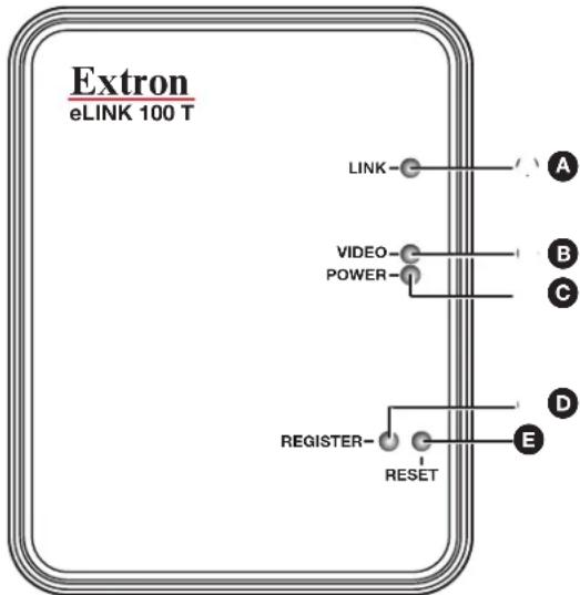
Figure 6. eLink 100 T Transmitter Top Panel
A Link LED — Blinks while the receiver is searching for a link to register with the transmitter (see Registering the Transmitter with the Receiver on page 10). When a link has been made, this LED lights steadily.
B Video LED — If the transmitter is registered with the receiver, this LED lights steadily when a valid source video format is detected and transmitted (see Resolutions and Rates table on page 18).
C Power LED — Lights steadily while power is connected to the transmitter.
Register button — Hold this button after starting the registration process on the receiver (see Registering the Transmitter with the Receiver on page 10).
E Reset button — Press this button to reset the transmitter, if needed for troubleshooting (see Troubleshooting on page 20).
Receiver Buttons and LEDs
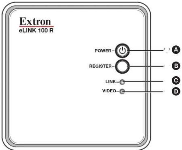
Figure 7. eLink 100 R Receiver Top Panel
Power button — Hold this button to power on the eLink 100 receiver. The blue LED behind this button lights to indicate that power is on.
NOTE: By default, the blue LED in this button lights and the receiver is powered on when power is connected to the unit.
B Register button — Press this button to initiate the registration process between the receiver and transmitter (see Registering the Transmitter with the Receiver on the next page).
Link LED — This blue LED blinks while the receiver is searching for a transmitter (see Registering the Transmitter with the Receiver). When a link has been made, this LED lights steadily.
D Video LED — This blue LED lights steadily when the transmitter and receiver are linked and a valid source video format is detected.
Operation
This section describes the operation of the eLink 100 extender, including:
- Operating Modes
• Registering the Transmitter with the Receiver
• Using the Remote Control and the OSD Menus
Operating Modes
The eLink 100 can operate in two modes:
• One transmitter linked with one receiver.
• One transmitter linked with up to four receivers.
NOTES:
- Up to four transmitter units can operate in the same room or environment. If a maximum of four transmitters is reached, the next group of units should be separated to prevent interference (see Best Practices for eLink 100 Mounting Locations on page 17).
- Maintain at least 6.5 feet (2 meters) between multiple eLink transmitters or multiple eLink receivers. Be mindful of units located beyond walls in adjacent rooms.
To establish communication between the eLink 100 transmitter and receiver, the transmitter must be registered with the receiver as explained below.
Registering the Transmitter with the Receiver
After registration is performed at the initial setup, the transmitter and receiver connect automatically when booted. Registration is not required again unless the transmitter is unregistered or removed from the receiver memory (see Unregistering a transmitter on page 14).
The units can be registered using the eLink 100 remote control (provided) or using the register buttons on the eLink 100 units.
Registering Using the Remote Control
NOTE: The remote control must be pointed at the IR sensor on the front panel of the receiver (see figure 3, A on page 6) from a distance of no more than 30 feet (9.1 meters) and no more than 40° from center.
To register the transmitter with the receiver using the eLink 100 remote control:
- Connect and apply power to the transmitter, input source, receiver, and output source.
NOTE: The registration process can be done without an input connected. In this case, a message on the OSD indicates that there is a missing video source.
-
Press the Add button on the remote control (see figure 8, © on page 12). The following message appears on the OSD: Please Activate Registration on Transmitter Unit.
-
Press and hold the Register button (see figure 6, D on page 8) on the transmitter top panel until the following message appears on the OSD: Adding transmitter name. Press OK to continue or Exit to cancel.
- Press the 0K button on the remote control (see figure 8, E on page 12) to confirm. The message Adding transmitter name... and a progress bar appear on the OSD while the registration process is completing.
NOTE: Registration may take up to 60 seconds to complete. If the process is delayed more than 60 seconds, cycle power on both units, and then restart the registration process.
When registration is complete, the message and progress bar disappear from the display. The Link LED and the Video LED light steadily.
Registering Using the Register Buttons
To register the transmitter with a receiver without using the remote control:
- Connect and apply power to the transmitter, input source, receiver, and output source.
NOTE: The registration process can be done without an input connected. In this case, a message on the OSD indicates that there is a missing video source.
Press and hold the Register button (see figure 7, B on page 9) on the receiver top panel until the following message appears on the OSD: Please Activate Registration on Transmitter Unit.
Press and hold the Register button on the transmitter top panel (see figure 6, D) until the following message appears on the OSD: Adding transmitter name. Press OK to continue or Exit to cancel
- Press the Register button on the receiver to confirm. The message Adding transmitter name... and a progress bar appear on the OSD while the registration process is completing.
NOTE: Registration may take up to 60 seconds to complete. If the process is delayed more than 60 seconds, cycle power on both units, and then restart the registration process.
When registration is complete, the message and progress bar disappear from the display. The Link LED (see figure 7, Ⓒ) and the Video LED (D) light steadily.
Registering an Additional Receiver
To register an additional receiver with a transmitter:
- Power down all receivers except the one being registered.
- Perform steps 2 through 4 above for the preferred method of registering the receiver (using the remote control or using the register buttons).
- When registration is complete, power on the other receivers. The video should be displayed on all monitors.
Using the Remote Control and the OSD Menus
Remote Control Buttons
Use the eLink 100 IR remote to control and navigate the OSD.
NOTE: The remote control must be pointed at the IR sensor on the front panel of the receiver (see figure 3, A, on page 6) from a distance of no more than 30 feet (9.1 meters) and no more than 40° from center.
CAUTION:
A Menu
B Exit
© Source
D Direction arrows
E OK
F Delete
G Add
H Guest (Not Used)
① Input Devices buttons (Not Used)
Figure 8. eLink 100 IR Remote Control
A Menu — Displays the OSD Setup menu (see Using the Setup Menu on the next page).
B Exit — Returns to the previous menu. If the Setup menu is displayed, pressing this button closes the OSD.
Source — Displays the Select Video Source menu, which lists the transmitter that is registered to the receiver.
NOTE: The eLink 100 does not support applications with multiple transmitters to one receiver. Only one transmitter should be used with as many as four receivers.
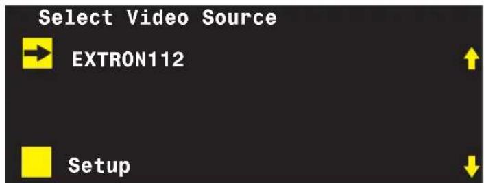
Figure 9. Select Video Source
Direction arrows — The up and down arrow buttons scroll through menu items. The right and left arrow buttons select characters when changing a video source name (see Modifying a video source name on the next page).
NOTE: In the OSD screen, the yellow arrows on the right (see figure 9 on the previous page) indicate that there are additional menu items to scroll through.
E OK — Selects the menu item.
F Delete — Displays the Choose Source to Remove submenu (see Unregistering a transmitter on the next page). This menu may also be accessed from the Setup menu by selecting Remove Video Source.
Add — Begins the registration process (see Registering the Transmitter with the Receiver on page 10).
Using the Setup Menu
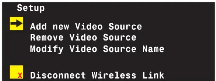
Figure 10. Setup Menu
The Setup menu includes the following options:
- Add new Video Source — Select this option to register the transmitter with a receiver. The message Please Activate Registration on Transmitter Unit appears (see Registering the Transmitter with the Receiver on page 10 for the rest of the registration procedure)
- Remove Video Source — Select this option to unregister a transmitter (see Unregistering a transmitter on the next page).
- Modify Video Source Name — Select this option to edit the name of an existing video source (see Modifying a video source name on the next page).
- Disconnect Wireless Link — This appears on the menu only if the source is displayed. Select this option to remove the connection between the source and the display.
Unregistering a transmitter
To unregister a transmitter (remove a video source) from a receiver:
- Power on the receiver.
- From the Setup menu, select Remove Video Source. This opens the Choose Source to Remove menu.
NOTE: Alternatively, you may press the Delete button on the remote control to access this menu.
- From the Choose Source to Remove menu, select the name of the source to be unregistered.
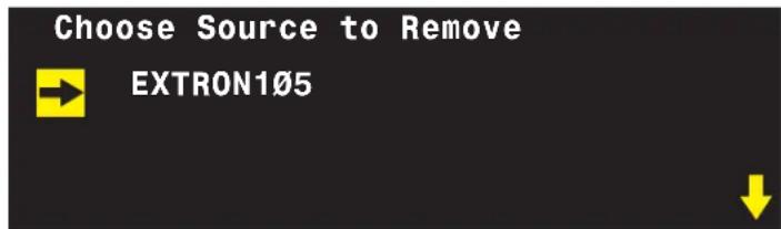
Figure 11. Choose Source to Remove OSD Menu
- The message Removing transmitter name. Press OK to continue or Exit to Cancel is displayed. Press the OK button again to delete the source. (To stop the removal procedure, press the Exit button.)
NOTE: While the transmitter is being unregistered, the message Removing transmitter name... is displayed. After approximately 30 seconds, the OSD closes, indicating the source has been removed and the transmitter unregistered.
Modifying a video source name
To change the name of a video source:
- Press the Menu button on the remote control to display the Setup menu.
- From the Setup menu, select Modify Video Source Name.
- From the Choose Source to Rename menu, select the source to be renamed. The Rename Video Source Name screen appears, displaying only the name to be changed.
- Use the right and left arrow buttons on the remote control to move focus to the first character that you want to change.
-
Press the up or down arrow buttons repeatedly until the desired replacement letter or number is displayed.
-
To step through the alphabet in ascending (A-to-Z) order, use the up arrow. The down arrow moves through the alphabet in descending (Z-to-A) order.
-
When you scroll through the characters in ascending order, the OSD displays the letters of the uppercase alphabet, followed by the lowercase alphabet, then a space, then digits 0 through 9, after which the display cycles back through, starting with the uppercase letters. In descending order, this sequence is reversed.
-
Press the OK button. The Select a Video Source menu is displayed.
-
Select a source from the menu to display or press the Exit button to close the OSD.
Reference Information
This section includes the following reference information:
- Mounting the Transmitter and Receiver
• Resolutions and Rates
• Operating Frequencies - Troubleshooting
Mounting the Transmitter and Receiver
ATTENTION:
NOTE: Before mounting, see Best Practices for eLink 100 Mounting Locations on page 17.
The eLink 100 units can be placed on a table or mounted to a wall. For the transmitter and receiver to communicate, they must be no further than 100 feet (30 meters) apart with a clear line of sight.
To mount the transmitter or receiver to a wall or furniture:
- Print and cut out the template for the unit to be mounted (cutout templates are available at www.extron.com).
- Tape the template to the wall at the desired location.
- Mark the location of the mounting hole centers on the wall or furniture (see figure 12).
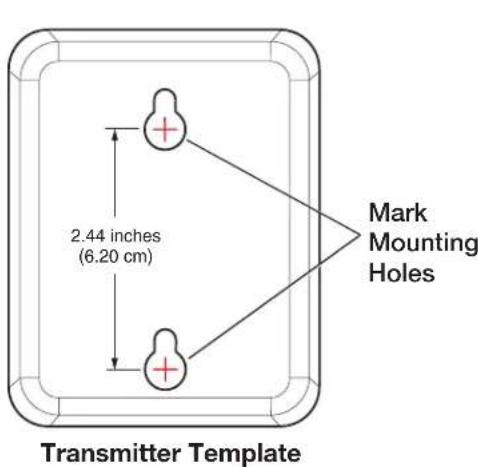
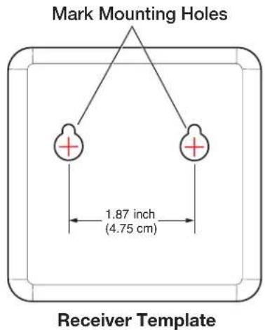
Figure 12. Mark the Center of the Two Mounting Hole Circles
-
Remove the template from the wall.
-
Drive two screws into the marked locations (see figure 13 for screw sizes).
NOTES:
- If drilling pilot holes, ensure that the size of the pilot holes is appropriate for the mounting screws used.
• Wall anchors may be required depending on wall material and stud locations.
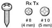
Pan Head
Figure 13. Screw Sizes for the eLink 100 Transmitter (Tx) and Receiver (Rx)
NOTE: Choice of screw length depends on wall or furniture thickness.
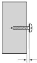
- Tighten the screws until the screw heads protrude from the wall at the following distances:
• Transmitter: approximately 3/16 inch (4.7 mm)
- Receiver: approximately 1/4 inch (6.4 mm)
If necessary, adjust the screw protrusion so that the eLink 100 unit is firmly secured on the wall or furniture surface.
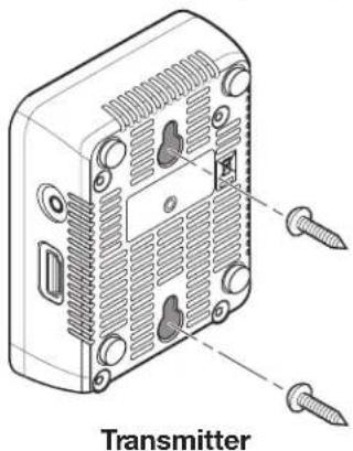
- Align the mounting holes on the back panel of the unit with the two screws protruding from the wall (see figure 14).
natural_image
Technical illustration of a device's internal structure with screw fasteners, labeled 'Transmitter' (no other text or symbols)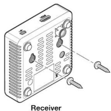
natural_image
Diagram of a device rear panel with screw holes and labeled 'Receiver' (no other text or symbols)Figure 14. Mounting the eLink 100 Units
- Slide the unit downward until both screws are seated in the narrow parts of the two keyholes.
Best Practices for eLink 100 Mounting Locations
For transmitter-to-receiver applications (one transmitter linked with up to four receivers):
- Ensure that the receivers are within a 100 foot (30 meter) radius of the transmitter with a clear line-of-sight (see figure 15).
- Maintain a distance of at least 6.5 feet (2 meters) between the eLink 100 transmitter and receiver.
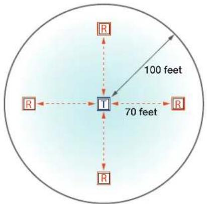
Figure 15. One-to-Four Application
For applications involving several transmitter-receiver pairs:
- Up to four transmitter units can operate in the same room or environment. If a maximum of four transmitters is reached, the next group of units should be separated to prevent interference. Ensure that there is at least a 150 foot (45 meter) radius around the outermost units in each group (see figure 16).
- Maintain a distance of at least 6.5 feet (2 meters) between individual eLink 100 transmitters and receivers. Be mindful of units located beyond walls in adjacent rooms.
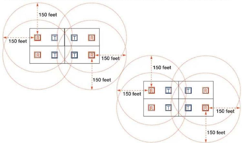
Figure 16. Application with Groups of eLink 100 Transmitter-Receiver Pairs
Resolutions and Rates
The following tables list the video and 3D resolutions and rates that the eLink 100 supports.
| Format | Resolution | Refresh Rates in Hz | |||||||||
| 50 Hz | 60 Hz 72 | Hz 23.98 | Hz 24 Hz | 25 Hz 59 | .94 Hz 29 | .97 Hz 30 | Hz 70 Hz | ||||
| 480i 720 (1) | 440) x 480 X X | ||||||||||
| 480p | 640 x 480 | X | X | ||||||||
| 720 x 480 | X | X | |||||||||
| 576i 720 (1) | 440) x 576 | X | |||||||||
| 576p 720 x | 576 | X | |||||||||
| 720p 1280 | x 720 | X | X | X | |||||||
| 1080i 1920 | x 1080 | X | X | X | |||||||
| 1080p | 1920 x 1080 | X | X | X | XX | X | X | X | |||
| VGA | 640 x 480 | X | X | ||||||||
| SVGA | 800 x 600 | X | X | ||||||||
| XGA 1024 | x 768 | X | X | ||||||||
| WXGA | 1280 x 800 | X | |||||||||
| WXGA | 1366 x 768 | X | |||||||||
| WXGA+ | 1440 x 900 | X | |||||||||
| SXGA+ | 1400 x 1050 | X | |||||||||
| 1600 x 900 | X | ||||||||||
| WSXGA+ | 1680 x 1050 | X | |||||||||
| 3D Rates | |||||||||||
| 720p 1280 | x 720 | X | X | X | X | X | X | X | |||
| 1080i 1920 | x 1080 | X | X | X | |||||||
| 1080p | 1920 x 1080 | X | X | X | X | X | X | X | |||
Operating Frequencies
The eLink 100 uses DFS (Dynamic Frequency Selection) technology, which actively monitors the RF spectrum to select the most appropriate frequencies. This prevents interference from other devices operating in the 5 GHz spectrum.
For reference, the table below lists the operating frequencies and their range (DFS or Non-DFS).
| Frequency (MHz) | Range | Regions | ||
| US/Canada/South Africa | Europe/Hong Kong/Singapore/UAE/Saudi Arabia/Qatar | Australia | ||
| 5190 | Non-DFS | XXX | ||
| 5230 XXX | ||||
| 5270 | DFS | XXX | ||
| 5310 XXX | ||||
| 5510 XXX | ||||
| 5550 XXX | ||||
| 5590 X | ||||
| 5630 X | ||||
| 5670 XXX | ||||
| 5755 | Non-DFS | X | ||
| 5795 X | ||||
NOTES:
- Up to four transmitter units can operate in the same room or environment. Each transmitter unit occupies one of these frequencies.
- If a maximum of four transmitters is reached, the next group of units should be separated to prevent interference (see Best Practices for eLink 100 Mounting Locations on page 17).
- Some Wi-Fi routers and access points also use the 5 GHz frequency band. Monitor the 5 GHz frequency usage between these products and multiple eLink 100 units, and plan systems to avoid interference.
Troubleshooting
The following table gives recommended actions to solve problems that may occur during setup or operation. If the problem persists after performing the recommended action, contact Extron S3 Support.
| Problem Actions | |
| Registration failure Ensure that both the transmitter and receiver are powered on. | |
| No signal on display Ensure that the receiver is powered on. | |
| IR remote control malfunctions | Ensure that the clear plastic film covering the battery contacts is removed before using the IR remote. |
| Ensure that the remote control batteries are fully charged. | |
| Ensure that there is enough distance between the receiver IR sensor and any fluorescent lighting or radiation that could interfere with the IR signals. | |
| A Searching...message displays, and the Link LED blinks continuously. | The eLink 100 can take up to 60 seconds to establish a wireless link. If the link is not established within that time, verify that the transmitter is powered on and not connected to another receiver. |
| The message Connected to source name, please check video source is displayed. | Check the HDMI connection between the transmitter and the video source. |
| A connection failure message appears, followed by the message Wireless Off. | If more than one registered transmitter is present and the receiver fails to connect to a transmitter within one to two minutes, the receiver goes into standby mode and shuts down the radio frequency. To connect to the desired source, press the Source button on the remote control and select the desired source from the OSD menu. |
| The Link LED blinks rapidly and there is no video on the display. | Cycle power to the unit. If the problem persists, contact the Extron S3 Sales and Technical Support Hotline. |
| Power cycle the receiver and transmitter units. You may also reset the transmitter using the Reset button (see figure 6, E on page 8). | |
| A link cannot be established, or audio or video quality is poor. | Decrease the distance between the transmitter and receiver and remove any obstacles between them. |
| The message Please wait, this action may take up to 60 sec" appears for more than 60 seconds. | This message may appear during registration process. If this message appears for more than 60 seconds, cycle power on both units, then restart the registration process. |
| Power cycle the receiver and transmitter units. You may also reset the transmitter using the Reset button (see E on page 8) | |
Extron Warranty
Extron Electronics warrants this product against defects in materials and workmanship for a period of three years from the date of purchase. In the event of malfunction during the warranty period attributable directly to faulty workmanship and/or materials, Extron Electronics will, at its option, repair or replace said products or components, to whatever extent it shall deem necessary to restore said product to proper operating condition, provided that it is returned within the warranty period, with proof of purchase and description of malfunction to:
USA, Canada, South America, and Central America:
Extron Electronics
1230 South Lewis Street
Anaheim, CA 92805
U.S.A.
Japan:
Extron Electronics, Japan
Kyodo Building, 16 Ichibancho
Chiyoda-ku, Tokyo 102-0082
Japan
Europe and Africa:
Extron Europe
Hanzeboulevard 10
3825 PH Amersfoort
The Netherlands
China:
Extron China
686 Ronghua Road
Songjiang District
Shanghai 201611
China
Asia:
Extron Asia Pte Ltd
135 Joo Seng Road, #04-01
PM Industrial Bldg.
Singapore 368363
Singapore
Middle East:
Extron Middle East
Dubai Airport Free Zone
F13, PO Box 293666
United Arab Emirates, Dubai
This Limited Warranty does not apply if the fault has been caused by misuse, improper handling care, electrical or mechanical abuse, abnormal operating conditions, or if modifications were made to the product that were not authorized by Extron.
NOTE: If a product is defective, please call Extron and ask for an Application Engineer to receive an RA (Return Authorization) number. This will begin the repair process.
USA: 714.491.1500 or 800.633.9876
Europe: 31.33.453.4040
Asia: 65.6383.4400
Japan: 81.3.3511.7655
Units must be returned insured, with shipping charges prepaid. If not insured, you assume the risk of loss or damage during shipment. Returned units must include the serial number and a description of the problem, as well as the name of the person to contact in case there are any questions.
Extron Electronics makes no further warranties either expressed or implied with respect to the product and its quality, performance, merchantability, or fitness for any particular use. In no event will Extron Electronics be liable for direct, indirect, or consequential damages resulting from any defect in this product even if Extron Electronics has been advised of such damage.
Please note that laws vary from state to state and country to country, and that some provisions of this warranty may not apply to you.

- Safety Instructions • English
- Trademarks
- FCC Class B Notice
- Safety Notices
- USA—FCC and FAA
- FCC Radio Frequency Interference Requirements
- USA—Federal Communications Commission (FCC)
- Security IC Compliance
- Canada, Industry Canada (IC) Notices
- ATTENTION:
- Radio Frequency (RF) Exposure Information
- IC Antenna Statement
- European Union
- Conventions Used in this Guide
- Notifications
- Specifications Availability
- Contents
- Introduction.... 1
- Installation....4
- Operation....10
- Reference Information 15
- Introduction
- About this Guide
- About the eLink 100 Transmitter and Receiver
- Features
- Installation
- Before Getting Started
- NOTE: For best performance:
- Front and Side Panel Features and Connections
- NOTES:
- Receiver Connections
- Installing the Plug on the Power Supply
- The eLink 100 On-Screen Display
- Top Panel Features and Functions
- Receiver Buttons and LEDs
- Operation
- Operating Modes
- Registering the Transmitter with the Receiver
- Registering Using the Remote Control
- Registering Using the Register Buttons
- Registering an Additional Receiver
- Using the Remote Control and the OSD Menus
- Remote Control Buttons
- CAUTION:
- Using the Setup Menu
- Unregistering a transmitter
- Modifying a video source name
- Reference Information
- Mounting the Transmitter and Receiver
- Best Practices for eLink 100 Mounting Locations
- For transmitter-to-receiver applications (one transmitter linked with up to four receivers):
- For applications involving several transmitter-receiver pairs:
- Resolutions and Rates
- Operating Frequencies
- Troubleshooting
- Extron Warranty
- USA, Canada, South America, and Central America:
- Japan:
- Europe and Africa:
- China:
- Asia:
- Middle East:
Brand : Extron
Model : eLink 100
Category : Audio/video extender