FPHD 51 TS X - Range hood Fulgor Milano - Free user manual and instructions
Find the device manual for free FPHD 51 TS X Fulgor Milano in PDF.


| Product Type | Downdraft range hood |
| Brand | Fulgor Milano |
| Model | FPHD 51 TS X |
| Installation Type | Built-in, downdraft |
| Modes | Suction (external evacuation) and recirculation (filtering) |
| Suction Speeds | 4 speeds |
| Motor Type | Internal or external (external motor sold separately) |
| Maximum Air Capacity | Internal motor models: >650 m³/h at 4th speed |
| Timer Function | 10-minute timer; auto speed reduction from 4th to 3rd after 6 min (internal motor), or 4th to 2nd after 6 min (external motor); automatic shut-off after 4 hours |
| Filter Saturation Alert | Grease filter: after 30 hours; reset by holding timer button |
| Grease Filters | Washable (hand or dishwasher) |
| Charcoal Filter | Replaceable (for recirculation mode); replace every 6 months |
| Electrical Connection | 220-240 V, 50/60 Hz, single-phase; requires earth connection and RCD (30 mA) |
| Power Cord | H05 VVF 3x0.75 mm² (L, N, E) |
| Cut-out Dimensions (Hole) | 490 mm x A (A depends on hob size) |
| Exhaust Pipe Diameter | 150 mm constant diameter |
| Max Pipe Length | 5 meters (with two 90° elbows: 3 meters) |
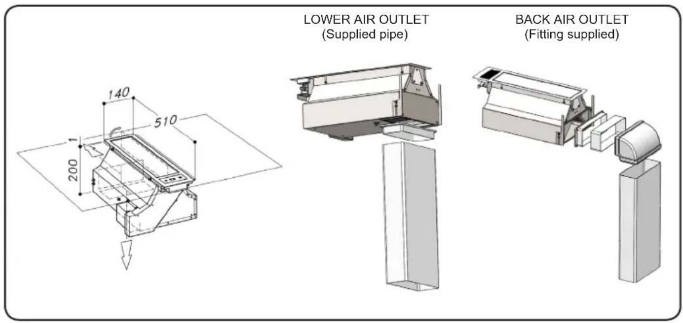
| Air Outlet Options | Lower or rear (fitting supplied) |
| Control Panel | Front panel opens to 90°; keys for speed increase/decrease, timer, on/off |
| Standby Power | <0.5 W |
| Safety Features | Automatic shut-off; filter saturation alarm; disconnection required before cleaning |
| Compliance | EU directives 2006/95/EC, 2004/108/EC, 2012/19/EC (WEEE) |
Frequently Asked Questions - FPHD 51 TS X Fulgor Milano
User questions about FPHD 51 TS X Fulgor Milano
0 question about this device. Answer the ones you know or ask your own.
Ask a new question about this device
Download the instructions for your Range hood in PDF format for free! Find your manual FPHD 51 TS X - Fulgor Milano and take your electronic device back in hand. On this page are published all the documents necessary for the use of your device. FPHD 51 TS X by Fulgor Milano.
USER MANUAL FPHD 51 TS X Fulgor Milano
natural_image
Simple diagram showing a black object above a horizontal bar with three wavy lines below, no text or symbols present.FPHD 52 TS BK
FPHD 52 TS WH
FPHD 51 TS X
natural_image
Symbol of a trash bin crossed out by two diagonal lines, with a blank rectangular base (no text or numbers present)natural_image
Symbol of a trash bin crossed out by two diagonal lines, with a black rectangular base below (no text or labels)The symbol on the product or on its packaging indicates that this product may not be treated as household waste. Instead it shall be handed over to the applicable collection point for the recycling of electrical and electronic equipment. By ensuring this product is disposed of correctly, you will help prevent potential negative consequences for the environment and human health, which could otherwise be caused by inappropriate waste handling of this product. For more detailed information about recycling of this product, please contact your local city office, your household waste disposal service or the shop where you purchased the product. This appliance is marked according to the European directive 2012/19/EC on waste electrical and electronic equipment (WEEE).
IMMAGINI IMAGES
natural_image
3D diagram of a mechanical component with a downward arrow indicating force or movement, labeled 'Fig. 1' (no text or symbols on the diagram itself)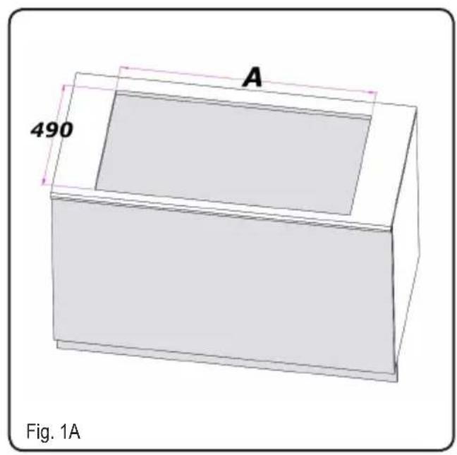
natural_image
3D mechanical assembly diagram showing a component with mounting base and internal structure, labeled Fig. 2 (no text or symbols on the diagram itself)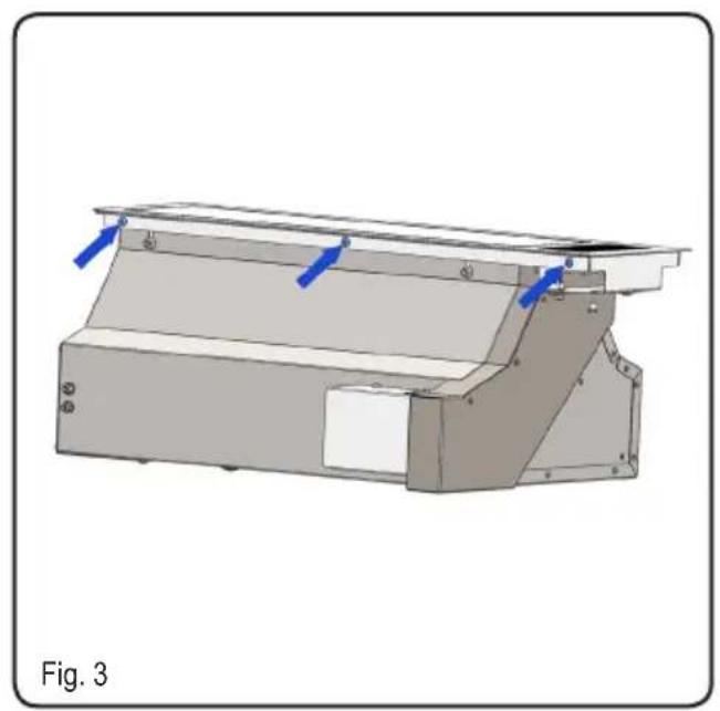
natural_image
3D mechanical assembly diagram showing a bracket with blue arrows indicating force or movement, labeled 'Fig. 3' (no text or symbols on the diagram itself)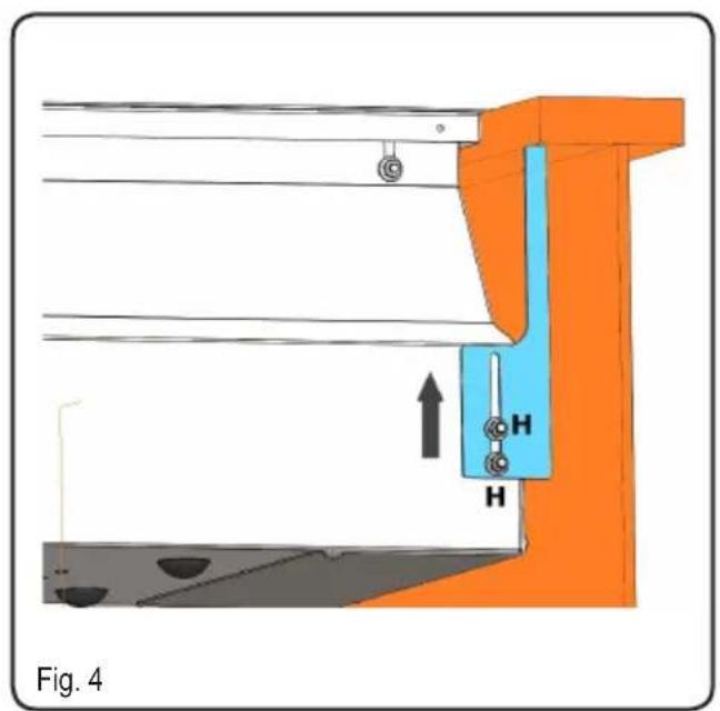
natural_image
Technical diagram of a mechanical assembly with orange components and labeled parts (no readable text or symbols)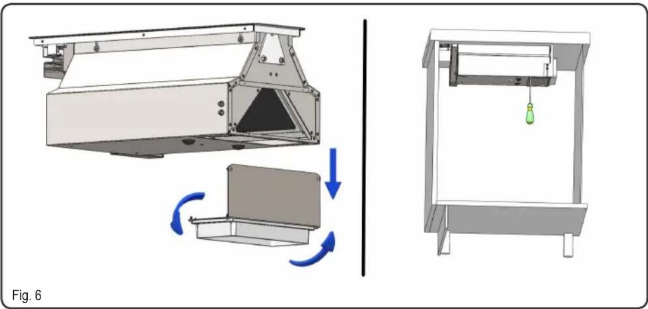
natural_image
3D rendering of two colored rectangular blocks on a base plate, one gray and one yellow, with no visible text or symbols.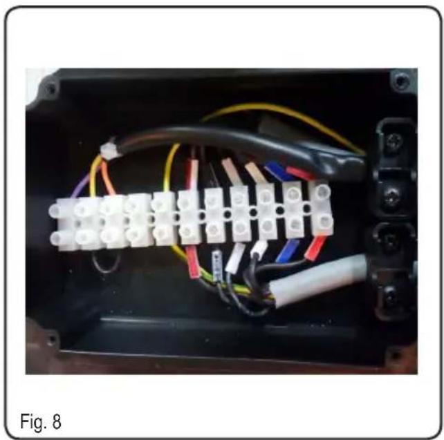
natural_image
Interior view of an electronic device showing terminal connectors and wiring (no text or symbols visible)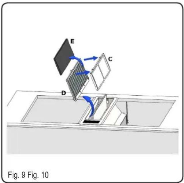
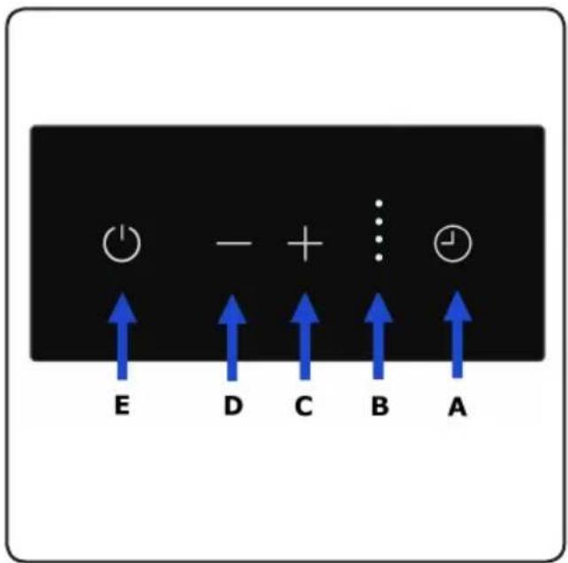
Fig. 11
natural_image
Technical diagram of a mechanical device with two blue arrows indicating downward flow or movement, no text or symbols present.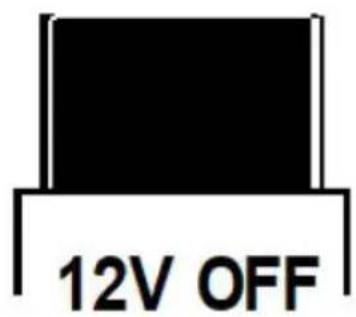
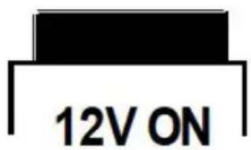
Fig. 12
natural_image
3D mechanical assembly diagram showing a housing and rotating component with directional arrows (no text or symbols)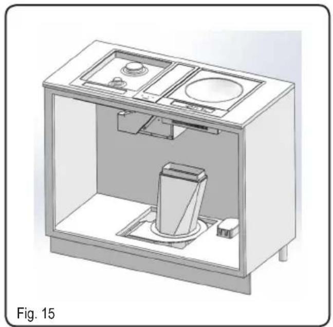
natural_image
3D technical illustration of a mechanical or electrical enclosure with internal components and mounting base (no text or symbols)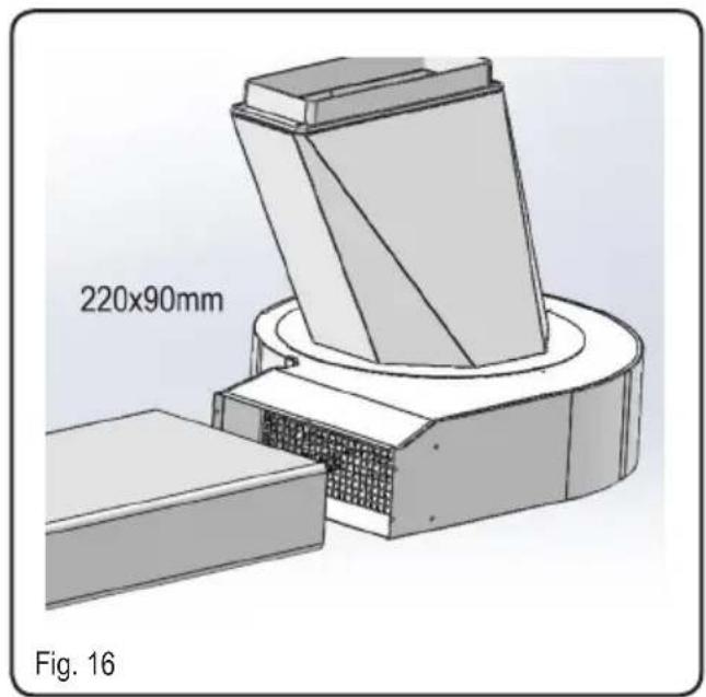
natural_image
3D technical illustration of a mechanical assembly with labeled dimensions (230x80mm) and figure number Fig. 17 (no text or symbols on the diagram itself)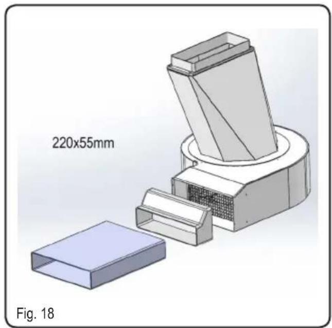
natural_image
3D mechanical assembly diagram showing a component with a 220x55mm dimension label and a separate box-like structure (no readable text or symbols beyond labels)It is designed to work in both suctioning mode, with outside evacuation, and filtering mode.

WARNING

Keep these instructions for use with the appliance. If the appliance should be sold or passed on to others, make sure that the instructions are passed on with it. We thank you for taking note of these suggestions before installing and using the appliance. They have been written for your personal safety and the safety of others.
SAFTEY INSTRUCTIONS
- This appliance can be used by children aged from 8 years and above and persons with reduced physical, sensory or mental capabilities or lack of experience and knowledge if they have been given supervision or instruction concerning use of the appliance in a safe way and understand the hazards involved.
- Children shall not play with the appliance.
- Cleaning and user mainte nance shall not be made by children without supervision.
- When the appliance is delivered, check the overall appearance of the packaging.
Any remarks should be written on the delivery coupon, of which you keep a copy.
Your appliance is designed for normal domestic use. It is not designed for commercial or industrial use, or for purposes other than those for which it was designed.
- Any consequences of or damage from incorrect installation or incorrect use of the appliance will not be covered by the manufacturer's guarantee.
- Do not ever change or try to change the characteristics of this appliance. This would be a danger. Repairs must be performed only by an authorised technician.
Always disconnect the hood before carrying out cleaning or maintenance operations.
- The room must be adequately ventilated if the hood and other appliances powered by energy other than electricity are used at the same time. This prevents the hood from sucking in any combustion fumes.
- Frying under the appliance must be done under constant supervision as hot oils and fats may ignite. Respect the guidelines for cleaning and replacement of grease filters. Accumulated deposits of grease are a fire hazard.
- This appliance must not be used over cook tops powered by wood or coal or in any case, over cook tops with power levels that could damage the appliance.
Never use steam or high-pressure devices for cleaning your hood (regulations regarding electrical safety).
- Never use the cooker hood without the greas filters.
Constantly seeking to improve our products, we reserve the right to modify their technical, functional, or aesthetic characteristics deriving from their upgrading.
In the case of the version with external motor, for normal downdraft operation, it is necessary to use a suctioning unit (external motor) made by the same manufacturer.
- The air must not be discharged into a flue that is used for exhausting fumes from ap pliances burning gas or other fuels (not applicable to appliances that only discharge the air back into the room);
Do not flambé under the range hood.
WARNING: This appliance and its accessible parts are likely to become very hot if used in combination with cooking devices.
- To evacuate the air outlet, please comply with the pertaining rules given by competent authorities.
-
When performing the elec trical connections on the ap pliance, please make sure that the current-tap is provided with earth connection and that vol tage values correspond to tho se indicated on the label placed inside the appliance itself.
-
If the supply cord is damaged, it must be replaced by the ma nufacturer, its service agent or similarly qualified persons in order to avoid a hazard.
- Before carrying out any cleaning or maintaining opera tions, the appliance needs to be removed from the electric grid. If the appliance is not provided with a non-separable flexible cable and plug, or with another device ensuring omni polar disconnections from the grid, with an opening distance between the contacts of at least 3 mm, then such disconnecting devices must be supplied within the fixed installation.
If the fixed appliance is endo wed with a supply cord and a plug, the appliance has to be put in a place where the plug can be reached easily.
- There is a fire risk if cleaning is not carried out in accordance with the instructions;
Should the product show any anomaly, disconnect the ap plian ce from the power supply.
When the range hood and ap pliances supplied with energy other than electricity are si multaneously in operation, the negative pressure in the room must not exceed 4 Pa (4 x 10⁻⁵ bar).
CONTENTS
DESCRIPTION OF THE APPLIANCE 22
INSTALLING THE PRODUCT 23
Grease filter removal, mounting the activated charcoal filter 24
Electrical connection of the hood 24
CLEANING THE PRODUCT 27
OPERATIONAL ANOMALIES 28
AFTER SALES SERVICE 28
DESCRIPTION OF THE APPLIANCE
FPHD 52 TS BK - WH FPHD 51 TS X
INSTALLING THE PRODUCT
- Before carrying out the appliance installation, please check that all components are not damaged, in such a case contact your retailer and do not carry out any installation operation.
Furthermore, please read carefully all of the following installation instructions.
- Use an air exhausting pipe whose maximum length does not exceed 5 meters.
- Limit the number of elbows in the piping, since each elbow reduces the air capacity of 1 linear meter. (Ex.: if you use no. 2 × 90^ elbows, the length of piping should not exceed 3 meters).
- Avoid abrupt direction changes.,
- Use a 150 mm. constant diameter pipe for the whole length.
- Use piping approved by standards in force.
The manufacturer shall not be deemed re-sponsible for air capacity or noise problems caused by failure to comply with the above instructions and no warranty on the product shall be provided.
-
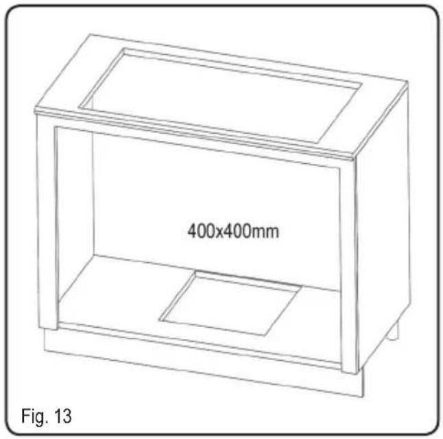
Before making the hole, check that there are no structural or other parts inside the cabinet, where the appliance is to be placed, which could hinder a proper installation. Check that the dimensions of the product and the ones of the cook top are compatible with the cabinet so that the installation can be carried out properly.
-
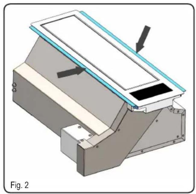
Carry out a rectangular hole of the dimensions of 490mm x A, (fig. 1A), the dimension A changes depending on the size of the hob. The product is equipped with two angles to support the hobs (fig. 2), before installing the product check the actual need for these components and if not remove them by removing the screws in fig. 3.
-
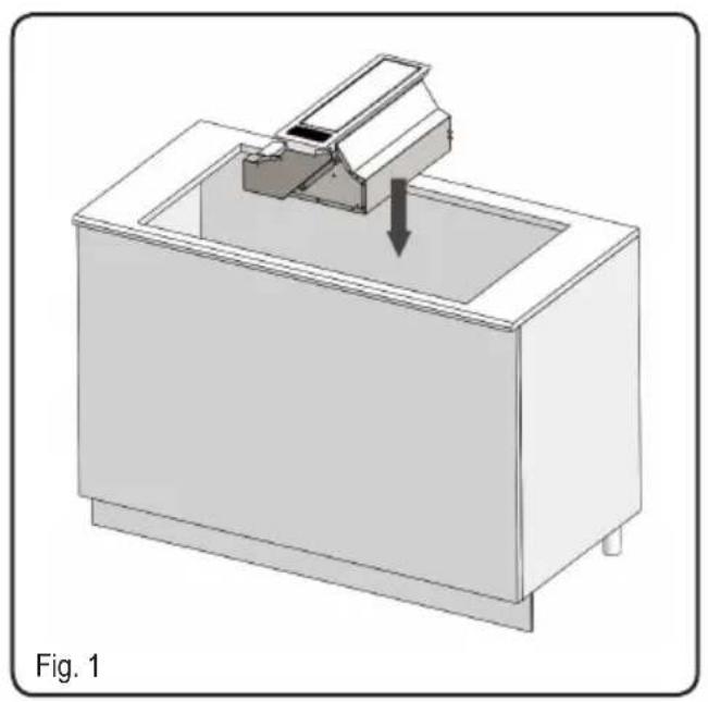
Install the product in the hole drilled, inserting it from above (Fig. 1).
-
Secure the product inside the furniture by using the specific brackets provided.
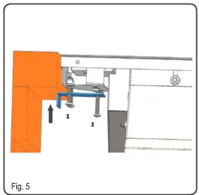
Proceed to the installation of the brackets in the sides of the product, in the specific hooks, as shown in fig. 4-5. Mount the rear brackets on both sides of the product, lift them up until they touch the support cabinet and then tighten the nuts "H" (fig.4).
Then fix the front bracket bringing it to touch on the cabinet by tightening the screws "I", as shown in figure 5.
Be careful to pull the screws "I" gently, by hand and without using electric screwdrivers, otherwise you could damage the product. -
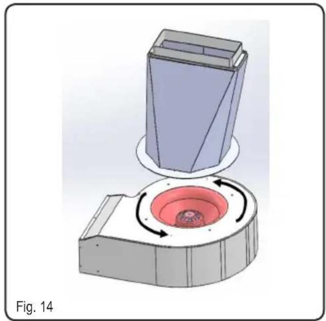
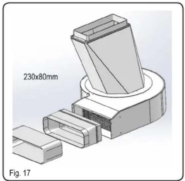
If the Downdraft is equipped with external motor, place the intake unit (external motor) and settle the exhaust air duct.
Then fit the air outlet ducts between the external motor and the product. Select the air outlet among the two available options and fit the union supplied with the appliance.
If you intend to use the rear exit air, you will first have to remove the flange from product, install the product in the furniture then restore the flange as shown in fig. 6.
For the installation of the external motor, refer to the relative booklet. -
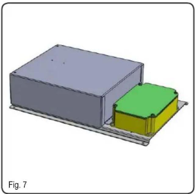
Place the metal box containing the electronic components in an easily reachable area for possible technical assistance operations, by connecting the related connectors (fig. 7).
-
If the product is equipped with external motor, connect the motor unit cable to the specific terminal board found the plastic box shown in fig. 8.
-
Connect the product to the power supply and check that the red button is in the fully down position (fig.12).
-
After completing the installation and connecting the appliance to the power supply, activate the product as indicated in the "HOW THE COOKER HOOD WORKS" part.
With the front panel open, install the grease filters (fig.9 "D") complete with carbon filter (fig.9 "E") through the special grid (fig.9 "C"), in case of filtering version, while in case of suction version, insert only the grease filter (fig.9 "D").
HOW TO USE THE COOKER HOOD
This appliance is intended to suck cooking fumes, greases and steam. It has been designed to work in both suctioning mode, with outside evacuation, and filtering mode.
Outside - discharge version
The cooker hood can be mounted in the version with outside discharge of suctioned air: in this case it is necessary to connect the exhausting channel to the outside (exhausting pipes are not supplied with the products.)
Filtering mode
In case fumes and vapour cannot be evacuated outside, the appliance can be used in the filtering mode.
Activated charcoal filters are required for this type of cooker hood.
Air recycled conveyed outside furniture.

CAUTION

Installation must comply with the regulations in force regarding the ventilation of enclosed environments. The use of discontinued ducts is not allowed without the approval of a qualified technician.
REMOVAL OF GREASE FILTER, MOUNTING THE CARBON FILTER (Fig.9)
The assembly and disassembly of grease filters and carbon filters must be made with the down draft in the open position. For this, actuate the opening of the front as indicated by the operation section.
Remove the grease filter (fig.9 "D"), place the carbon filter (fig.9 "E") inside the special grid (fig.9 "C") and insert the grid on the grease filter using special tabs.
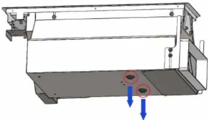
If there is liquid inside the product, it is possible to remove it by removing the caps located under the hood housing (fig.11).

WARNING

After having replaced the filters, reinstall the front stainless steel pan'el, otherwise the Downdraft is not enabled to function.
ELECTRICAL CONNECTION OF THE COOKER HOOD

WARNING

Place the metal box containing the electronic components at a distance of no less than 65 cm from cook tops or in any case, 65 cm from the suctioning surface of the cookerhood.

NOTA

We recommend installing the metal box containing the electronic components at least 10 cm above floor level and at a suitable distance from all heat sources (e.g. oven sides or cook top).

CAUTION

This appliance is fitted with an H05 VVF 3 conductor, 0.75 mm2 (neutral, phase, and ground) power cord.
This can be connected up to a 220 - 240 V mono-phase electrical network through a CEI 60083 approved power socket, which must remain accessible after installation, in compliance with installation regulations.
We decline any responsibility in case of accidents caused by a lack of ground connection or incorrect ground connection. The appliance must be fed through a differential protection device (RCD), with a nominal residual current not exceeding 30mA. If the power cord is damaged, call the after-sales service to avoid any risk.

WARNING

The downdraft connection to the electrica network must be carried out only by professional and qualified technicians.
The downdraft must be connected to a properly installed and suitable electrical network. The electrical system must comply with VDE0100 standard.

DANGER

If the cooker hood presents any anomaly, disconnect the appliance or remove the fuse corresponding to the appliance power disconnecting line.
If the appliance has no plug or if the plug is not easily accessible, then a device needs to be fitted to cut it off from the electric network; this device must have an opening distance between contacts on all poles of at least 3 mm.
ELECTRICAL CONNECTION

NOTE

This appliance complies with the European Directives 2006/95/EC (Low Voltage Directive) and 2004/108/EC (Electromagnetic Compatibility).
While installing the appliance and carrying maintenance operation, make sure it is disconnected from the electrical network or the fuses are cut out or removed.
Check that:
- Power is enough.
- Feeder lines (mains) are in good conditions.
- The cables diameter complies with installation regulations.
A: 10 minutes timer, after which the suction motor is turned off and the front is closed.
The setting of the function is signaled by indicator flashing speed (B).
B: the suction motor speed indicator.
The 4 LEDs emit a RED light and light up according to the set speed.
First speed : 1 LED ON
Second speed : 2 LEDs ON
Third speed : 3 LEDs ON
Fourth speed : 4 LEDs ON
C: the key is only active with open front (90°). For each selection of the function there is an increase of
the suction motor speed, up to the fourth speed.
D: the key is only active with open front (90°).
Each time you select the function you have a speed decrease of the suction motor, up to the first speed.
E: with the product off, at the first touch it starts the opening of the front panel until it reaches the opening of 90^ , once the opening is reached the second speed of the suction motor is automatically set.
Pressing the button further stops the intake motor and closes the front panel completely.
TIMING
As a result of the new EU65 “Energy label” and EU66 “Ecodesign” regulations issued by the European Commission, which came into force as from January 1st, 2015, our products have been adapted to comply with these new requirements.
All of the models complying with the energy label requirements, are equipped with new electronics including a timer device for suction speeds control, when the air capacity exceeds 650m^3/h .
Internal motor models, with maximum air capacity higher than 650m^3/h , are equipped with a timer device that automatically switches the suction speed from 4th to 3rd speed, after 6 minutes operation.
External motor models are equipped with remote motors that, as for internal motor versions, include a timer device that switches down the suction speed when it exceeds 650 m³/h. (See External Motors Instructions)
Remote motors, whose air capacity exceeds 650m^3/h at both 4th and 3rd speed, will have the following by default timer control functions:
The suction speed is automatically switched from 4th to 2nd speed, after 6 minutes operation.
If the appliance is working at 3rd speed, it is automatically switched to 2nd speed, after 7 minutes operation. Operation speeds can also be changed during operation.
The energy consumption of the appliance in stand – by mode is lower than 0.5W.
Other functions:
Automatic turn off:
After 4 hours of continuous operation from the last setup, the appliance turns off automatically.
Grease filters saturation
After 30 hours of operation, the speed indica tors "D" will all flash simultaneously, signaling the grease filters saturation. To reset this alarm, hold the "TIMER" button down for at least 3 seconds, while the extractable unit is open.
CLEANING THE
PRODUCT
Careful maintenance ensures proper operation and good performances over time.

CAUTION

The hood must be disconnected from the electrical network, both by unplugging the appliance from the socket and activating the magnetic circuit breaker (safety cut-out), before removing the metal grease filters. After cleaning operations, replace the metal grease filters as outlined in the installation instructions.
| MAINTENANCE HOW TO PROCEED? | ACCESSORY PRODUCTS TO USE | |
| External surfaces and accessories | Do not use metallic scrubbers, abrasive products, or hard brushes. | -To clean the external surfaces of the cookerhood and the light housing screen use only commercially available household detergents diluted in water. Then rinse with clean water and dry with a soft cloth. |
| grease filter | After 30 hours of operation, the downdraft will signal the grease filter saturation. Saturation is indicated by flashing RED color LED speed indicator, when the cooker hood is off. To reset, hold down the timer button for at least 3 seconds, while the hood is OFF. | The grease filters can be washed by hand or in the dishwasher. These filters need to be cleaned on a regular basis, because otherwise they may represent a fire risk. Refit the grease filters and front panel, making sure that the panis properly fitted at the sides so that it does not cause the downdraft to stop operating. |
| Activated charcoal filter | In the recirculation mode, the active charcoal filter must be replaced periodically. To remove the charcoal filter first of all it is necessary to remove the grease filter and then pull the plastic key of the panel itself, in order to disengage it from its seating. Follow these steps in reverse order to insert the active charcoal filter. Replace the used charcoal filter on an average of every six months. | |
OPERATIONAL
ANOMALIES
| PROBLEM SOLUTION | |
| The cooker hood does not work... | Check that:There is not a power outage.A specific speed has actually been selected.The red reset key, found over the electrical system box, is pushed. |
| The cooker hood has low performances... | Check that:The motor speed selected is sufficient for the quantity of fumes and vapors present in the room.The kitchen is ventilated well enough to allow air for intake.The charcoal filter is not worn out.( filtering version cooker hood).The air outlet channel is free and compliant with paragraph no. 2.The non-return valves of the suctioning unit are free to rotate. |
| The cooker hood stops in the middle of operation. | Check that:There is not a power outage.The omnipolar device has not tripped. |
AFTER SALES SERVICE
Any maintenance operation on your appliance should be carried out by:
- Either your retailer;
- Or another qualified professional technician, authorized for that brand.
FULGOR
MILANO
SINCE 1949
- IMMAGINI IMAGES
- WARNING
- SAFTEY INSTRUCTIONS
- CONTENTS
- DESCRIPTION OF THE APPLIANCE
- INSTALLING THE PRODUCT
- HOW TO USE THE COOKER HOOD
- Outside - discharge version
- Filtering mode
- CAUTION
- ELECTRICAL CONNECTION OF THE COOKER HOOD
- NOTA
- DANGER
- ELECTRICAL CONNECTION
- NOTE
- TIMING
- Other functions:
- Grease filters saturation
- CLEANING THE
- PRODUCT
- OPERATIONAL
- ANOMALIES
- AFTER SALES SERVICE
- FULGOR
Brand : Fulgor Milano
Model : FPHD 51 TS X
Category : Range hood