FCAXV1U - Projector Accessories Chief - Free user manual and instructions
Find the device manual for free FCAXV1U Chief in PDF.


| Product Type | Pull-Out Accessory for Projector Mount |
| Brand | Chief |
| Model | FCAXV1U |
| Compatibility | XTM1U and XSM1U Mounting Systems |
| Number of Pullout Assemblies | 3 |
| Material | Steel |
| Weight Capacity (Max) | 250 lbs (113.4 kg) depending on wall substrate |
| Wall Bracket Offset | 16.00 in (406.4 mm) |
| Display Mounting Pattern (with FCAB10HS) | 15.75 in x 16.00 in (400 mm x 406.4 mm) |
| Display Mounting Pattern (with FCA810HS) | 23.62 in x 16.00 in (600 mm x 406.4 mm) |
| Max Down Plumb | 19.50 in (495.3 mm) |
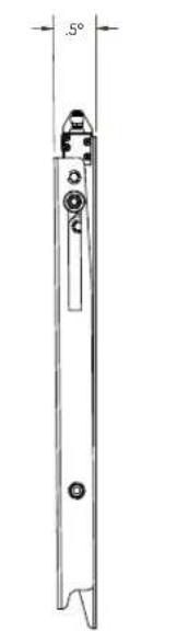
| Plumb Adjustment Range | Up to 5° (via adjustment nut) |
| Installation Wall Requirements | Wood stud, concrete, concrete block, or steel stud (triple 16" on-center 2x4-25ga min.) |
| Safety Factor Required | Mounting structure must support 5x combined weight of equipment |
| Retainer Latch | Yes, holds brackets in retracted position |
| Included Hardware | Lag bolts, anchors, washers, screws (see manual for details) |
| Use | Indoor use only; allows pulling mount away from wall for servicing |
| Warranty | Refer to manufacturer (Legrand AV) |
Frequently Asked Questions - FCAXV1U Chief
User questions about FCAXV1U Chief
0 question about this device. Answer the ones you know or ask your own.
Ask a new question about this device
Download the instructions for your Projector Accessories in PDF format for free! Find your manual FCAXV1U - Chief and take your electronic device back in hand. On this page are published all the documents necessary for the use of your device. FCAXV1U by Chief.
USER MANUAL FCAXV1U Chief
INSTALLATION INSTRUCTIONS
natural_image
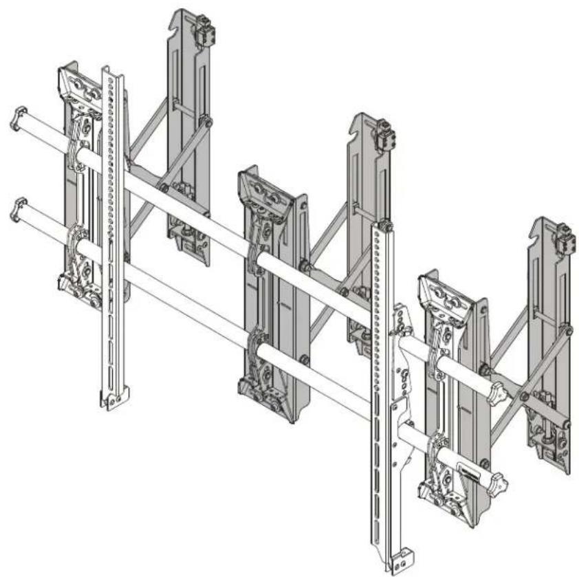
Technical line drawing of a mechanical assembly with vertical supports and mounting brackets (no text or symbols)XL Fusion Pull-Out Accessory
DISCLAIMER
Legrand | AV and its affiliated corporations and subsidiaries (collectively “Legrand | AV”), intend to make this manual accurate and complete. However, Legrand | AV makes no claim that the information contained herein covers all details, conditions or variations, nor does it provide for every possible contingency in connection with the installation or use of this product. The information contained in this document is subject to change without notice or obligation of any kind. Legrand | AV makes no representation of warranty, expressed or implied, regarding the information contained herein. Legrand | AV assumes no responsibility for accuracy, completeness or sufficiency of the information contained in this document.
Chief® is a registered trademark of Legrand AV Inc.
DEFINITIONS
MOUNTING SYSTEM: A MOUNTING SYSTEM is the primary Chief product to which an accessory and/or component is attached.
ACCESSORY: AN ACCESSORY is the secondary Chief product which is attached to a primary Chief product, and may have a component attached or setting on it.
COMPONENT: A COMPONENT is an audiovisual item designed to be attached or resting on an accessory or mounting system such as a video camera, CPU, screen, display, projector, etc.

WARNING: A WARNING alerts you to the possibility of serious injury or death if you do not follow the instructions.

CAUTION: A CAUTION alerts you to the possibility of damage or destruction of equipment if you do not follow the corresponding instructions.

IMPORTANT SAFETY INSTRUCTIONS

WARNING: Failure to read, thoroughly understand, and follow all instructions can result in serious personal injury, damage to equipment, or voiding of factory warranty! It is the installer's responsibility to make sure all accessories are properly assembled and installed using the instructions provided.

WARNING: Failure to provide adequate structural strength for this accessory can result in serious personal injury or damage to equipment! It is the installer's responsibility to make sure the structure to which this accessory is attached can support five times the combined weight of all equipment. Reinforce the structure as required before installing the accessory.

WARNING: Exceeding the weight capacity can result in serious personal injury or damage to equipment! Adding the FCAXV1U accessory may change the weight capacity listed for the mounting system, and is dependent upon the mounting substrate. Consult (Table 1) for the XTM1U and XSM1U mounting systems' weight capacities when attached to the FCAXV1U and mounted to various mounting substrates.
Table 1: Weight Capacity When Attached to FCAXV1U
| Mounting Substrate | XTM1U Max Weight Allowed | XSM1U Max Weight Allowed |
| Triple 16" on-center 2" x 4"-25ga minimum steel studs wall | 200 lbs (90.7 kg) 200 | lbs (90.7 kg) |
| Triple 16" on-center 2" x 4" wood studs wall | 250 lbs (113.4 kg) 200 | lbs (90.7 kg) |
| 3/4" Plywood-backed steel stud wall covered with maximum drywall thickness of 5/8" | 250 lbs (113.4 kg) 200 | lbs (90.7 kg) |
| Bare 8" Concrete Wall | 250 lbs (113.4 kg) 200 | lbs (90.7 kg) |
| Bare 8"x8"x16" Concrete Block Wall | 250 lbs (113.4 kg) 200 | lbs (90.7 kg) |

WARNING: Use this accessory only for its intended use as described in these instructions. Do not use attachments not recommended by the manufacturer.

WARNING: Never operate this accessory if it is damaged. Return the accessory to a service center for examination and repair.

WARNING: Do not use this accessory outdoors.
NOTE: Accessory is intended to be used with the following Chief mounting systems (not included):
• X T M 1 U
• XSM1U
--SAVE THESE INSTRUCTIONS--
DIMENSIONS
FCAXV1U CONTAINS THREE SCISSORS
ASSEMBLIES AND ONE FUSION WALL ASSEMBLY
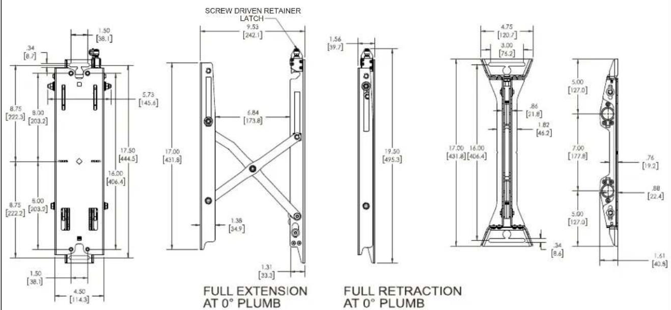
DIMENSIONS:
INCHES
[MILLIMETERS]
natural_image
Technical line drawing of a mechanical component with angular dimension (5°) and internal features, no text or symbols present.MAX DOWN PLUMB
![1.56 [39.7] 19.50 [495.3]](/content/2026/05/903575/images/de09f7e9517e1569a38d2de9bec3340a1e06e1d70973bfd4ba39ffcf0216bd02.jpg)
PLUMB AT 0^
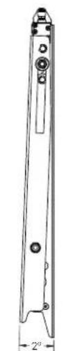
natural_image
Technical line drawing of a mechanical component with angular dimension标注 (2°), no readable text or symbols present.MAX UP PLUMB
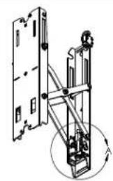
natural_image
Technical line drawing of a mechanical assembly with a rotating component (no text or symbols)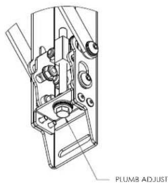
DETAIL A SCALE 1:2
DIMENSIONS:
INCHES
[MILLIMETERS]
DIMENSIONS -- continued
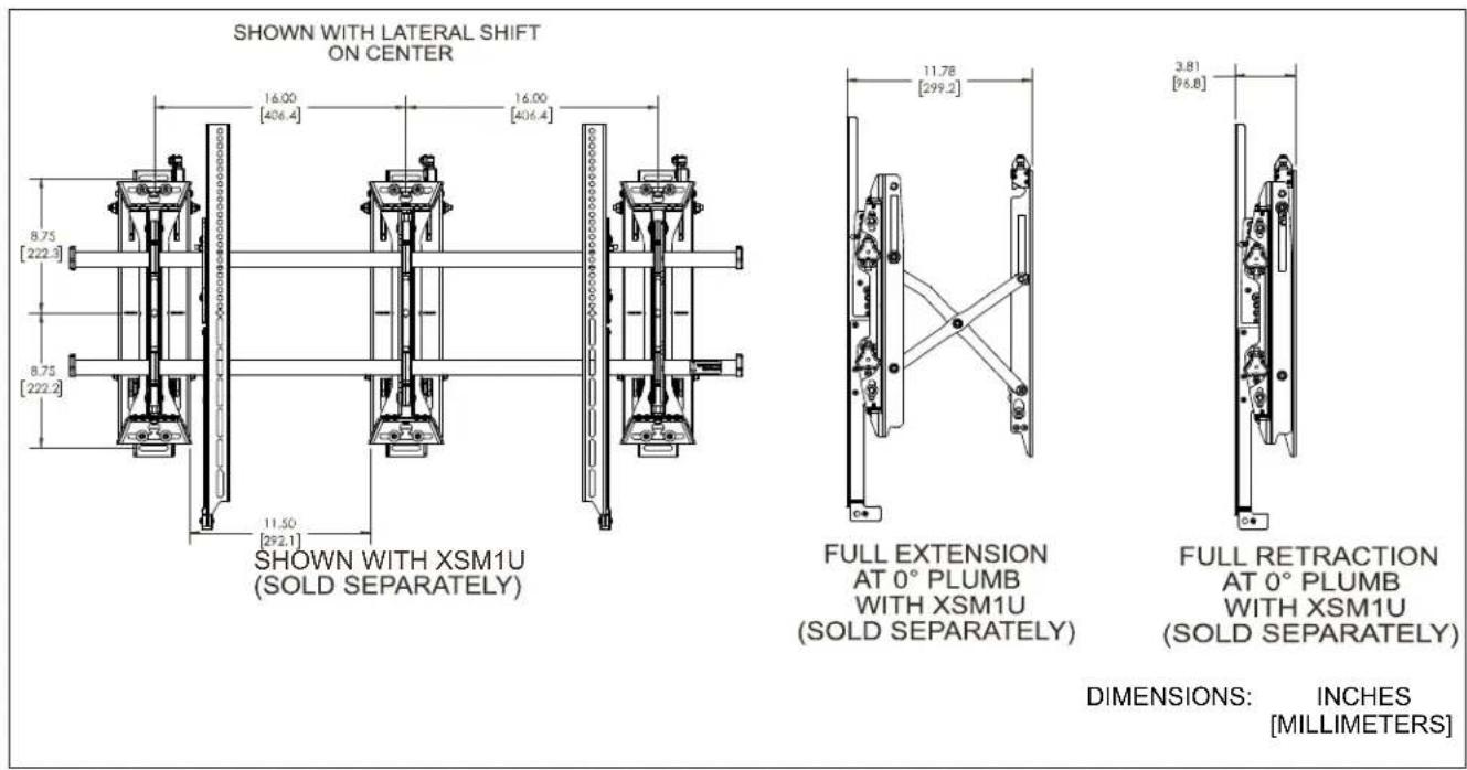
![16.00 [406.4] 4.30 [109.3] WALL BRACKET OFFSET 16.00 [406.4] SHOWN WITH FCAB10HS (NOT INCLUDED) 15.75 [600.0] DISPLAY MOUNTING PATTERN DISPLAY/CAMERA CENTER](/content/2026/05/903575/images/58621b12f6cdab8d745e9f090fce81db653d369f4627ec7be5776a9d709f3af9.jpg)
![16.00 [406.4] 4.75 [120.6] WALL BRACKET OFFSET 16.00 [406.4] SHOWN WITH FCA810HS (NOT INCLUDED) 23.62 [600.0] DISPLAY/CAMERA CENTER DISPLAY MOUNTING PATTERN](/content/2026/05/903575/images/88d948fbb30f4158491fa33906a08932f059fd865c91410e8fb394f8aa13b37b.jpg)
DIMENSIONS: INCHES [MILLIMETERS]
DIMENSIONS -- continued
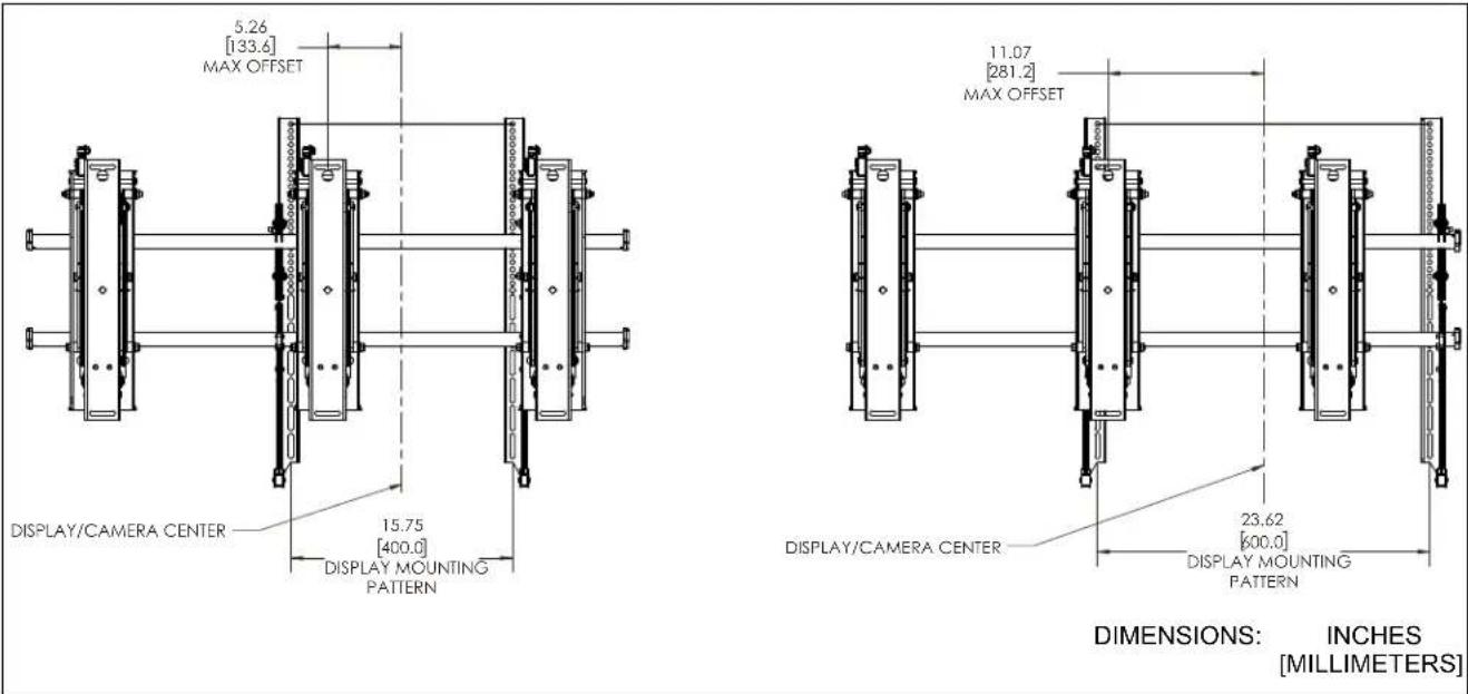
DIMENSIONS:
INCHES
[MILLIMETERS]
LEGEND
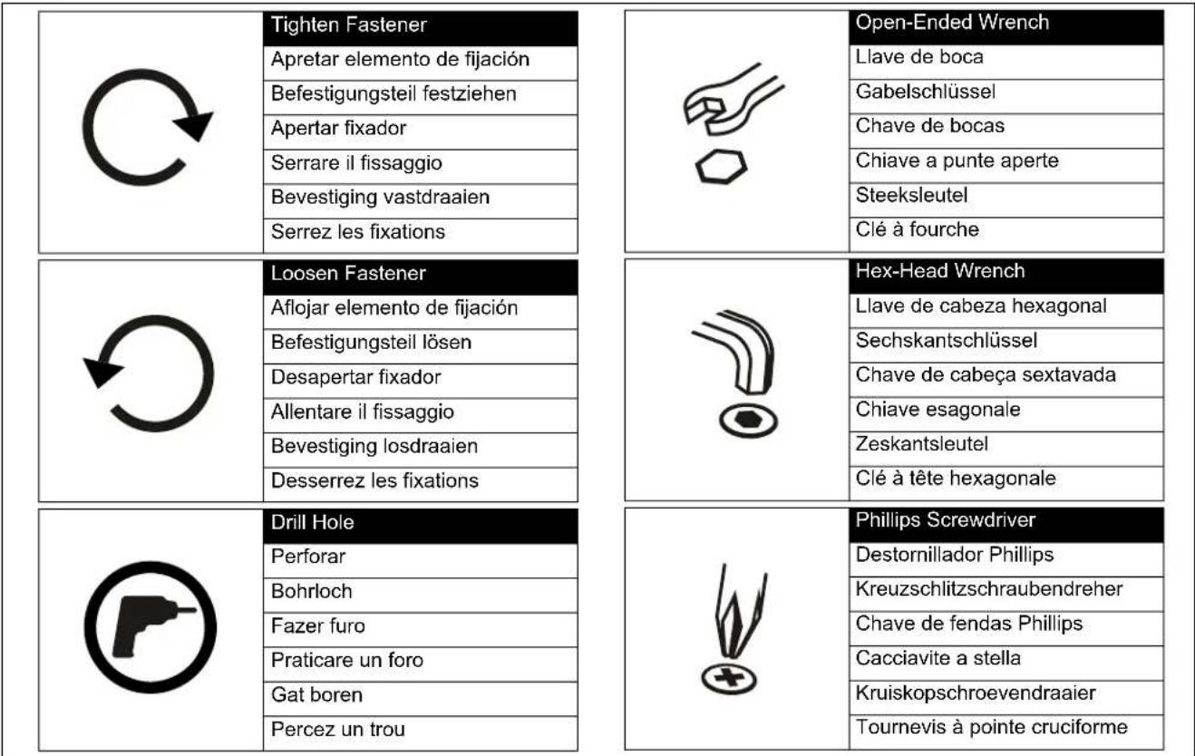
Tighten Fastener
Phillips Screwdriver
Destornillador Phillips
Hardware Required - not included (for installation into steel stud walls)
- Chief brand FCAT1 Toggler Kit; OR
- Hardware for installation to steel stud wall (except for plywood-backed steel stud):
• 1/4-20 Toggler Snaptoggle BB (Qty 6)
• 1/4-20 x 2-1/2" hex head bolt (Qty 6)
PARTS

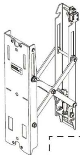
A (3)
[Fusion pullout accessory]
natural_image
Technical line drawing of a mechanical assembly with mounting brackets and joints (no text or symbols)![Wall-Mounting Hardware Kit B (6) 5/16 x 2-1/2" C (6) [Fischer UX10x60R] D (6) 5/16"](/content/2026/05/903575/images/13650d373f34f5e227f0b2c1e5b70e930f1dd63fa717863258fc0967cb17c53b.jpg)
FCAXV1U Hardware Kit
natural_image
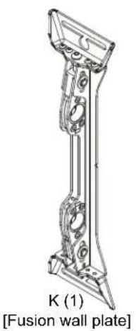
Technical line drawing of a mechanical component labeled K(1) with no readable text or symbols beyond the label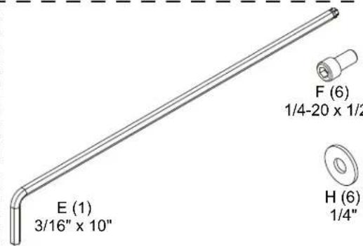
INSTALLATION
NOTE: The FCAXV1U enables the mounting system to be pulled out away from the wall for any servicing needs.
Locate Mounting Site

WARNING: IMPROPER INSTALLATION CAN LEAD TO MOUNT FALLING CAUSING SEVERE PERSONAL INJURY OR DAMAGE TO EQUIPMENT! It is the installers responsibility to make certain the structure to which the accessory is being attached is capable of supporting five times the combined weight of accessory and mount, not to exceed weight capacities listed in Table 1 (See Table 1)
NOTE: Proceed to either the Installing to a Wood Stud Wall/Plywood-Backed Steel Stud Wall, Installing to a Concrete/Concrete Block Wall, or Installing to a Steel Stud Wall section.
Installing to a Wood Stud Wall / Plywood-Backed Steel Stud Wall
IMPORTANT ! : See SITE REQUIREMENTS - Steel Stud Wall / Plywood-Backed Steel Stud Wall section before proceeding with Plywood-Backed Steel Stud installation to ensure installation site meets requirements! The drywall must have a minimum thickness of 1/2"! (See Figure 4)
IMPORTANT ! : For Plywood-Backed Steel Stud Wall there is NOT a requirement to install into studs.
- Determine the center of the TV screen, and where it should be located on the wall.
- Locate the closest stud to the left or right of the selected location, and then the next closest studs to the left and right of the center of screen marking.
NOTE: If the screen area lies over a stud, use that stud and the stud to both the left and right of it. - Line up the diamond cutouts on Fusion pullout (A) with center of screen marking to determine vertical center. (See Figure 1)
- Measure up 8.75" (222.3 mm) from the center point (by hooking tape measure in slots on front of FCAXV1U) to mark location of the upper mounting slots.
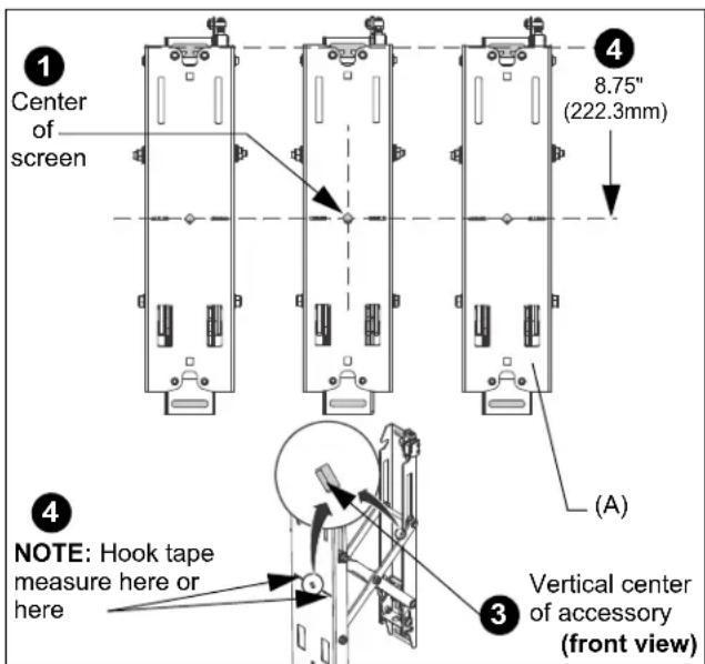
Figure 1
- Using a level, mark the wall on the three studs to attach the accessory through the upper mounting slots. (See Figure 2)
- Drill one 7/32" (5.5mm) pilot hole in each stud.
NOTE: The slotted washers have been included to help make the installation easier. Wait to place the slotted washer AFTER the Fusion pullouts are hanging on the partially installed lag bolts. (See Steps 7-10)
- Partially install three 5/16 x 2-1/2" flanged lag bolts (B) into pilot holes but do not tighten to wall.
- Hang three Fusion pullouts (A), aligning upper mounting slots over lag bolts and adjust side-to-side for proper location.
- Place one slotted washer (D) over each flanged lag bolt. (See Figure 2)
- Tighten lag bolts to secure accessory (A) to wall at upper mounting slots.
- Mark the attachment points for the lower mounting slots, making sure the attachment points are located on the studs. (See Figure 2)
- Drill 7/32" (5.5mm) pilot holes at markings for lower mounting holes. (See Figure 2)
- Use three 5/16 x 2-1/2" flanged lag bolts (B) and three 5/16" slotted washers (D) to attach three pullouts (A) to the wall through the lower mounting holes. (See Figure 2)
- Proceed to Attaching Mounting System section.
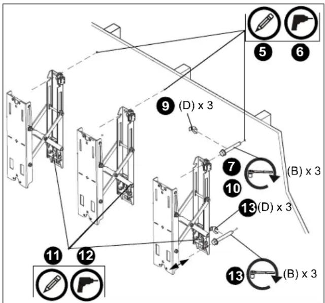
Figure 2
Installing to a Concrete/Concrete Block Wall
- Determine the center of the TV screen, and where it should be located on the wall.
- Line up the notches on Fusion pullout (A) with center of screen marking to determine vertical center. (See Figure 1)
- Measure up 8.75" (222.3) from the center point to mark location of the upper mounting slots. (See Figure 1)
- Using a level, mark the wall through three upper mounting slots. (See Figure 3)
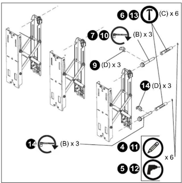
Figure 3

CAUTION: MINIMUM HORIZONTAL DISTANCE BETWEEN WALL BRACKETS IS 16" (406.4mm). Do not place FCAXV1U pullout accessories closer together than 16" (406.4mm).
- Drill one 3/8" x 3-1/2" (9.5mm x 88.9mm) pilot hole at each marking.
- Install an anchor (C) into each pilot hole using a hammer, making sure that the anchor is flush with the wall.
NOTE: The slotted washers have been included to help make the installation easier. Wait to place the slotted washer AFTER the Fusion pullouts are hanging on the partially installed lag bolts. (See Steps 7-10)
- Partially install three 5/16 x 2-1/2" flanged lag bolts (B) into pilot holes but do not tighten to wall.
- Hang accessory (A), aligning upper mounting slots over lag bolts, and adjust side-to-side for proper location.
- Place one slotted washer (D) over each flanged lag bolt. (See Figure 3)
-
Tighten lag bolts to secure Fusion pullout (A) to wall at upper mounting slots.
-
Mark the attachment points for the lower mounting slots, making sure the attachment points are located on the studs. (See Figure 3)
- Drill 3/8" x 3-1/2" (9.5mm x 88.9mm) pilot holes at markings for lower mounting holes. (See Figure 3)
- Install an anchor (C) into each pilot hole using a hammer, making sure that the anchor is flush with the wall.
- Use three 5/16 x 2-1/2" flanged lag bolts (B) and three 5/16" slotted washers (D) to attach the accessory to the wall through the lower mounting holes. (See Figure 3)
- Proceed to Attaching Mounting System section.
SITE REQUIREMENTS - Steel Stud Wall / Plywood-Backed Steel Stud Wall

WARNING: IMPROPER INSTALLATION CAN LEAD TO EQUIPMENT FALLING CAUSING SERIOUS PERSONAL INJURY OR DAMAGE TO EQUIPMENT! The figure below identifies the minimum requirements for installation of display mounts onto a steel stud structure. If the structure or its components do not meet these requirements contact the mount manufacturer for specific instructions before attempting installation. It should also be noted that no other equipment should be mounted to the same stud.

If back side of wall is unfinished, drywall must be installed to a minimum of one stud left and right of the stud(s) being used to install the mount. Drywall must be secured to studs with screws a maximum of 12" apart down center
![being used to install the mount. Drywall must be secured to studs with screws maximum of 12" apart down center 16" (on center) Studs There must be a minimum of 1-7/8" (48mm) clearance inside wall FRONT PLYWOOD-BACKED STEEL STUD STEEL STUD Drywall **1/2" minimum Drywall Thickness (Both Sides of Stud) **See hazard statement on page 2! Plywood 3/4" minimum thickness plywood covered with drywall 5/8" maximum drywall thickness (Both Sides of Stud) Steel Stud (2 x 4 / 25ga minimum) Stud type and structural strength must conform to the North American Specification for the Design of Cold-Formed Steel Structural Members. [362, 125 18, C-Shape, S - Stud Section]](/content/2026/05/903575/images/fa40b07c1ab51860db0df029fb084c272aa2075279240bc3be84f69cb5cb5b96.jpg)
Figure 4
Installing to a Steel Stud Wall
NOTE: Follow these instructions for steel stud walls constructed of triple 16" on-center 2" x 4"-25ga minimum steel studs.
IMPORTANT ! : See SITE REQUIREMENTS - Steel Stud Wall / Plywood-Backed Steel Stud Wall section before proceeding with Steel Studs installation to ensure installation site meets requirements! The drywall must have a minimum thickness of 1/2"! (See Figure 4)
IMPORTANT ! : If installing into plywood-backed steel studs, follow the directions and use hardware outlined in Installing to a Wood Stud Wall / Plywood-Backed Steel Stud Wall
IMPORTANT ! : Using a level, mark the wall on three studs for location of the accessory and drill 1/2" pilot holes at markings. Follow the directions outlined in Installing to a Wood Stud Wall / Plywood-Backed Steel Stud Wall using the hardware for installing to steel stud walls [Togglers and hex head bolts (not included)].
- Hold metal channel on anchor flat alongside plastic straps and slide channel through hole. (See Figure 5)
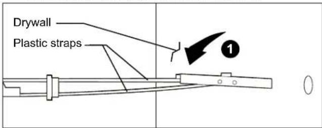
Figure 5
- Holding plastic straps on anchor, pull anchor away from wall until channel rests flush behind wall making sure anchor channel is positioned vertically on drywall, or steel stud (if present). (See Figure 6)
- Slide plastic cap on anchor towards wall until flange of cap is flush with wall. (See Figure 6)
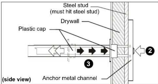
Figure 6
- Snap off plastic straps on anchor at wall by pushing side to side, snapping off straps level with flange of plastic cap. (See Figure 7)
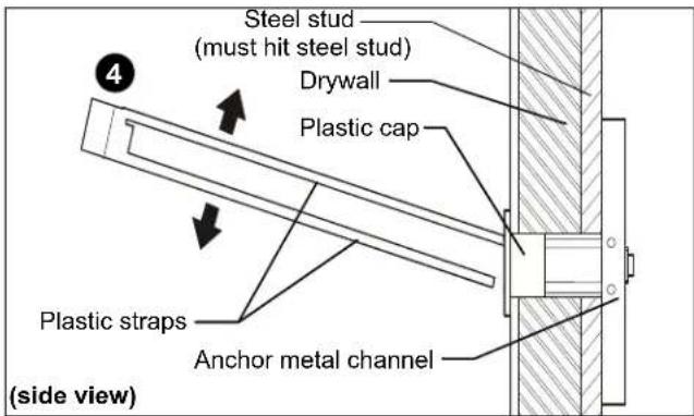
Figure 7
- Line up anchor with attachment point.
- Insert 1/4-20 x 1-3/4" Phillips pan head screw through 1/4" washer, corresponding mounting hole in wall bracket and into anchor, and tighten until flush against wall bracket. DO NOT over tighten! (See Figure 8)
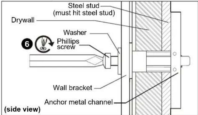
Figure 8
ATTACHING MOUNTING SYSTEM
- Remove caps from one side of mounting rails on XTM1U/XSM1U mount. (See Figure 9)
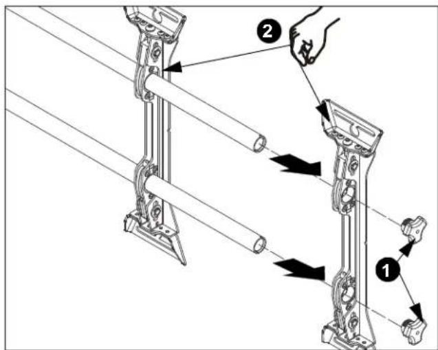
Figure 9
- Slide both Fusion wall plates off XTM1U/XSM1U mount rails. (See Figure 9)
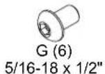
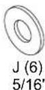
- Attach top of one Fusion wall plate [(K) and two wall plates removed from XTM1U/XSM1U] to each Fusion pullout (A) using two 5/16 x 1/2" button head cap screws (G) and two 5/16" washers (J) in each top mounting slot. (See Figure 10)
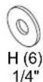
- Attach bottom of Fusion wall plates to bottom of Fusion pullout using two 1/4-20 x 1/2" socket head cap screws (F) and two 1/4" washers (H) in each bottom mount slot. (See Figure 10)
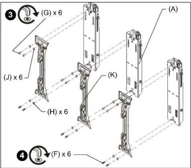
Figure 10
- Slide rails from the XTM1U/XSM1U mounting system through the three Fusion wall plates. (See Figure 7)
- Reattach end caps to the rails. (See Figure 7)
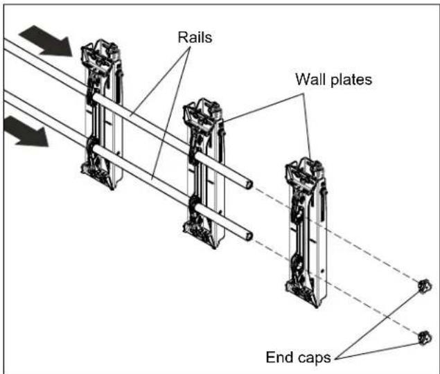
Figure 11
- The remainder of the mounting system installation may be completed at this time, following the installation instructions included with the mounting system.
ADJUSTMENTS
Moving Mount to Wall (Optional)
- Close the FCAXV1U brackets and tighten the retainer latch (turn counterclockwise) to hold the brackets in the retracted position. (See Figure 12)
IMPORTANT ! : Do NOT over-tighten the retainer latch.
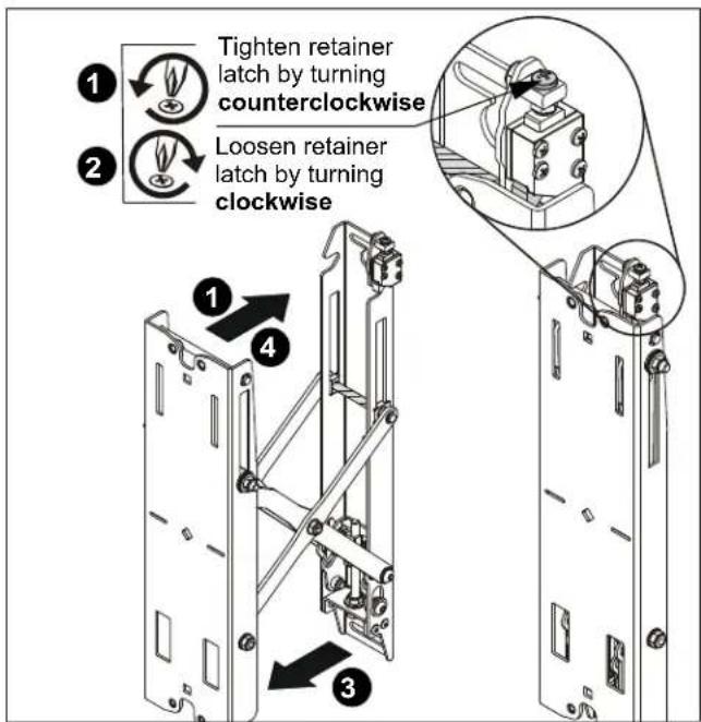
Figure 12
Moving Mount to Service Position
- Loosen the retainer latch by turning screw clockwise. (See Figure 12)
- Pull mount out from wall.
- Return mount towards wall after service is complete.
Adjusting Mount Against Wall
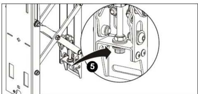
IMPORTANT ! : Carefully adjust the mount plumb evenly on both sides to avoid placing too much stress on the screen.
5. Adjust plumb of mount by turning the adjustment nut on the FCAXV1U. (See Figure 13)
natural_image
Technical diagram showing mechanical assembly with a magnified inset highlighting a component labeled '5' (no text or symbols present)Figure 13

CHIEF®
A brand of legrand
8800-003218 Rev00
©2020 Legrand | AV
www.legrandav.com
09/2020
USA/International A 6436 City West Parkway, Eden Prairie, MN 55344
P 800.582.6480 / 952.225.6000
F 877.894.6918 / 952.894.6918
Europe A Franklinstraat 14, 6003 DK Weert, Netherlands
P +31 (0) 495 580 852
F +31 (0) 495 580 845
Asia Pacific A Office No. 918 on 9/F, Shatin Galleria
18-24 Shan Mei Street
Fotan, Shatin, Hong Kong
P 852 2145 4099
F 852 2145 4477



- INSTALLATION INSTRUCTIONS
- DISCLAIMER
- DEFINITIONS
- IMPORTANT SAFETY INSTRUCTIONS
- DIMENSIONS
- Tighten Fastener
- Phillips Screwdriver
- PARTS
- INSTALLATION
- Locate Mounting Site
- Installing to a Wood Stud Wall / Plywood-Backed Steel Stud Wall
- Installing to a Concrete/Concrete Block Wall
- SITE REQUIREMENTS - Steel Stud Wall / Plywood-Backed Steel Stud Wall
- Installing to a Steel Stud Wall
- ATTACHING MOUNTING SYSTEM
- ADJUSTMENTS
- Moving Mount to Wall (Optional)
- Moving Mount to Service Position
- Adjusting Mount Against Wall
- CHIEF®
Brand : Chief
Model : FCAXV1U
Category : Projector Accessories