
CMS018024W - Projector Accessories Chief - Free user manual and instructions
Find the device manual for free CMS018024W Chief in PDF.


| Type | Extension Column for Projector Mounts |
| Brand | Chief |
| Model | CMS018024W |
| Weight Capacity | 500 lbs (226 kg) |
| Compatibility | 1-1/2" NPT (ANSI/ASME B1.20.1 Schedule 40, steel or aluminum) ceiling plates and mounts |
| Length Adjustment | Adjustable in 2" increments via locking slots; also 1" increments via adjustment holes (on columns 6" or longer) |
| Typical Length Range | 18 inches to 24 inches (based on model number) |
| Cable Access | Yes, on columns 9" or longer; optional exit below plate/adapter |
| Material | Steel or aluminum (ASTM B221) |
| Included Components | Column section, screws, lock washer, flat washer, set screws, hex keys (for adjustable version) |
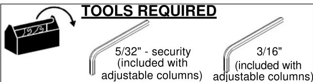
| Tools Required | 5/32" security hex key and 3/16" hex key (included with adjustable columns) |
| Installation | Must be installed into a compatible ceiling plate/adapter (not included); engage at least 4 full threads |
| Usage | Indoor use only |
| Safety Warning | Must support 5 times combined weight of all equipment; do not exceed 500 lbs capacity |
Frequently Asked Questions - CMS018024W Chief
User questions about CMS018024W Chief
0 question about this device. Answer the ones you know or ask your own.
Ask a new question about this device
Download the instructions for your Projector Accessories in PDF format for free! Find your manual CMS018024W - Chief and take your electronic device back in hand. On this page are published all the documents necessary for the use of your device. CMS018024W by Chief.
USER MANUAL CMS018024W Chief
Milestone AV Technologies and its affiliated corporations and subsidiaries (collectively "Milestone"), intend to make this manual accurate and complete. However, Milestone makes no claim that the information contained herein covers all details, conditions or variations, nor does it provide for every possible contingency in connection with the installation or use of this product. The information contained in this document is subject to change without notice or obligation of any kind. Milestone makes no representation of warranty, expressed or implied, regarding the information contained herein. Milestone assumes no responsibility for accuracy, completeness or sufficiency of the information contained in this document.
Chief® is a registered trademark of Milestone AV Technologies. All rights reserved.
DEFINITIONS
MOUNTING SYSTEM: A MOUNTING SYSTEM is the primary Chief product to which an accessory and/or component is attached.
ACCESSORY: AN ACCESSORY is the secondary Chief product which is attached to a primary Chief product, and may have a component attached or setting on it.
COMPONENT: A COMPONENT is an audiovisual item designed to be attached or resting on an accessory or mounting system such as a video camera, CPU, screen, display, projector, etc.

WARNING: A WARNING alerts you to the possibility of serious injury or death if you do not follow the instructions.

CAUTION: A CAUTION alerts you to the possibility of damage or destruction of equipment if you do not follow the corresponding instructions.

IMPORTANT SAFETY INSTRUCTIONS

WARNING: Failure to read, thoroughly understand, and follow all instructions can result in serious personal injury, damage to equipment, or voiding of factory warranty! It is the installer's responsibility to make sure all accessories are properly assembled and installed using the instructions provided.

WARNING: Failure to provide adequate structural strength for this accessory can result in serious personal injury or damage to equipment! It is the installer's responsibility to make sure the structure to which this accessory is attached can support five times the combined weight of all equipment. Reinforce the structure as required before installing the accessory.

WARNING: Exceeding the weight capacity can result in serious personal injury or damage to equipment! It is the installer's responsibility to make sure the combined weight of
all components attached to the CMS Series Extension Column does not exceed 500 lbs (226 kg).
- The weight capacity of the CMS Series Extension Columns may be LIMITED to the lowest weight capacity of any other component, accessory or mounting system used with this accessory.

WARNING: Do not use this product outdoors.

WARNING: Use this accessory only for its intended use as described in these instructions. Do not use attachments not recommended by the manufacturer.

WARNING: Never operate this accessory if it is damaged. Return the accessory to a service center for examination and repair.
NOTE: Chief CMS Series extension columns are Listed for use with all Listed Chief ceiling plates and mounts specified for use with 1-1/2" NPT following ANSI/ASME B1.20.1 (Schedule 40, 0.154" minimum thickness, steel or aluminum - ASTM B221) extension columns and the UL listed truss ceiling adapter accessory CMS380. CMS Series extension columns are suitable for a maximum 500 lbs (226 kg).
--SAVE THESE INSTRUCTIONS--
![PARTS A (1) [CMS adjustable length] OR A (1) [CMS fixed length]](/content/2026/05/811672/images/f961ee132811948d9f06658a6e2546108300a91e1206be96450b4f38b52119e1.jpg)
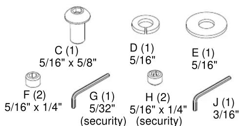
NOTE: Parts B-J are only included with adjustable length columns.
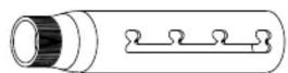
B (1)
FIXED LENGTH EXTENSION COLUMN
IMPORTANT ! : The following procedure assumes that the ceiling plate/adapter (not included) has been properly installed following instructions provided with ceiling plate/adapter.
NOTE: Intended for use with Chief accessories and mounts.
-
Install 1-1/2" NPT threaded column (A) into plate/adapter (See Figure 1). Securely tighten column.
-
Ensure column (A) engages four full threads into plate/adapter.
- Ensure cable access opening is rotated to desired position (optional installation).
NOTE: Cable access opening provided on columns 9" or longer (229mm) in length. Optional installation used when cables must exit below plate/adapter.
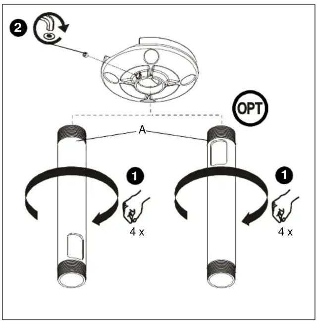
Figure 1
- Secure column (A) by tightening set screw in plate/adapter (See Figure 1).
NOTE: Hex key and set screw provided with plate/adapter.

WARNING: Exceeding the weight capacity can result in serious personal injury or damage to equipment! It is the installer's responsibility to make sure the combined weight of all components attached to the CMS Series Extension Column does not exceed 500 lbs (226 kg).
- The weight capacity of the CMS Series Extension Columns may be LIMITED to the lowest weight capacity of any other component or accessory used within the mounting system.
- Install and secure projector/display mount (not included) to lower end of column (A) following instructions included with mount.
ADJUSTABLE LENGTH EXTENSION COLUMN
IMPORTANT ! : The following procedure assumes that the ceiling plate/adapter (not included) has been properly installed following instructions provided with ceiling plate/adapter.
NOTE: Intended for use with Chief accessories and mounts.
-
Install 1-1/2" NPT threaded column (A or B, as applicable) into plate/adapter (See Figure 2). Securely tighten column.
-
Ensure column (A or B, as applicable) engages four full threads into plate/adapter.
- Ensure cable access opening is rotated to desired position (optional installation, column (A)).
NOTE: Cable access opening provided on columns 9" or longer (229mm) in length. Optional installation used when cables must exit below plate/adapter.
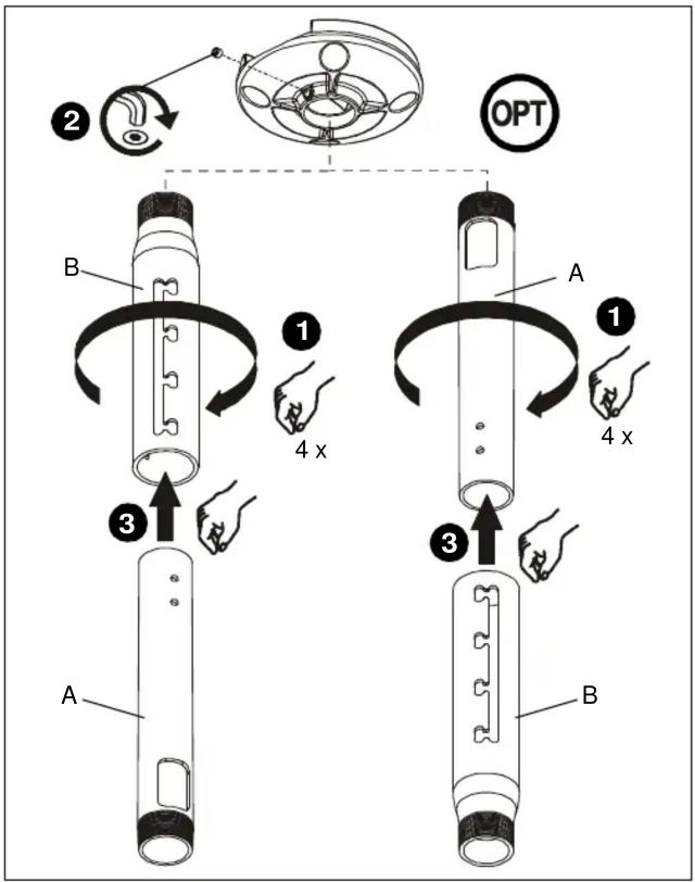
Figure 2
- Secure column (A or B, as applicable) by tightening set screw in plate/adapter (See Figure 2).
NOTE: Hex key and set screw provided with plate/adapter. -
Install mating column (A or B, as applicable) (See Figure 2).
-
Using key (J), loosely install screw (C) through lock washer (D), flat washer (E), and outer column (B) into adjustment hole in inner column (A) (See Figure 3).
NOTE: Two adjustment holes provided in columns 6" or longer (152mm) in length. Either adjustment hole can be used to provide 1" (25mm) adjustment increments.
NOTE: Optional installation similar; not shown.
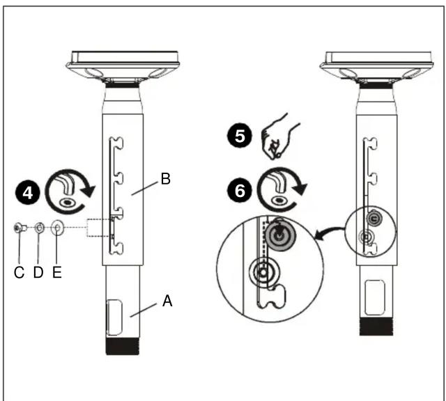
Figure 3
- Adjust column (A or B, as applicable) to desired length, then rotate and lock into position (See Figure 3).
NOTE: Any locking slot can be used to provide 2" (51mm) adjustment increments.
-
Tighten screw (C) using key (J) (See Figure 3).
-
Install and tighten set screws (standard (F) or security (H), as desired) using key (G) (See Figure 4).
NOTE: Optional installation similar; not shown.
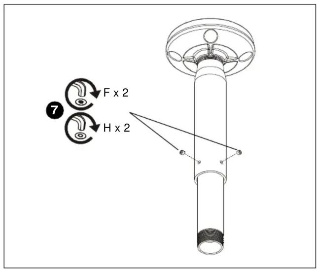
Figure 4

WARNING: Exceeding the weight capacity can result in serious personal injury or damage to equipment! It is the installer's responsibility to make sure the combined weight of all components attached to the CMS Series Extension Column does not exceed 500 lbs (226 kg).
- The weight capacity of the CMS Series Extension Columns may be LIMITED to the lowest weight capacity of any other component, accessory or mounting system used with this accessory.
- Install and secure projector/display mount (not included) to lower end of column (A or B, as applicable) following instructions included with mount.
Installation Instructions
DIMENSIONS
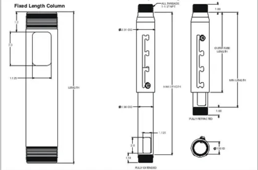
Adjustable Length Column


Brand : Chief
Model : CMS018024W
Category : Projector Accessories