
PG1A - Projector Accessories Chief - Free user manual and instructions
Find the device manual for free PG1A Chief in PDF.


| Product Type | Projector Mount |
| Brand | Chief |
| Model | PG1A |
| Compatibility | Most projectors with standard mounting holes (100x100 to 400x400 mm pattern) |
| Weight Capacity | Up to 50 lbs (22.7 kg) |
| Material | Steel with powder-coated finish |
| Color | Black |
| Dimensions | 10 x 10 x 5 inches (254 x 254 x 127 mm) |
| Weight | 3 lbs (1.36 kg) |
| Tilt Range | +/-15° |
| Swivel Range | +/-90° |
| Roll Adjustment | +/-3° |
| Mounting Type | Ceiling or wall mount |
| Installation Hardware | Included: lag bolts, concrete anchors, screws, and standard mounting adapter |
| Safety Features | Security screws to prevent tampering; built-in cable management |
| Maintenance | Periodically check bolts for tightness; clean with dry cloth |
| Spare Parts | Replacement security screws, adapter plates available from Chief |
| Repairability | Modular design; tilt/swivel mechanisms serviceable with basic tools |
| Certifications | UL listed |
| Warranty | 10 years limited warranty |
| Country of Origin | USA |
Frequently Asked Questions - PG1A Chief
User questions about PG1A Chief
0 question about this device. Answer the ones you know or ask your own.
Ask a new question about this device
Download the instructions for your Projector Accessories in PDF format for free! Find your manual PG1A - Chief and take your electronic device back in hand. On this page are published all the documents necessary for the use of your device. PG1A by Chief.
USER MANUAL PG1A Chief
INSTALLATION INSTRUCTIONS
natural_image
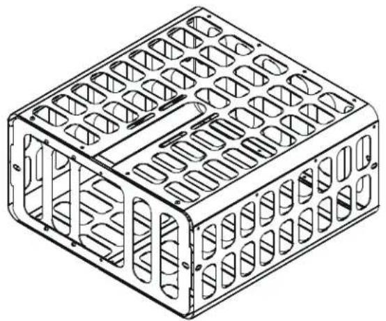
Isometric line drawing of a rectangular metal enclosure with internal grid patterns (no text or symbols)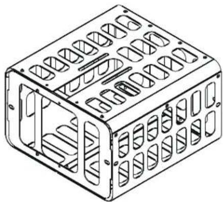
natural_image
Isometric line drawing of a rectangular metal enclosure with internal cutouts (no text or symbols)Projector Guard Security Cage
DISCLAIMER
CSAV, Inc., and its affiliated corporations and subsidiaries (collectively, "CSAV"), intend to make this manual accurate and complete. However, CSAV makes no claim that the information contained herein covers all details, conditions or variations, nor does it provide for every possible contingency in connection with the installation or use of this product. The information contained in this document is subject to change without notice or obligation of any kind. CSAV makes no representation of warranty, expressed or implied, regarding the information contained herein. CSAV assumes no responsibility for accuracy, completeness or sufficiency of the information contained in this document.

IMPORTANT WARNINGS AND TIONS!

WARNING: A WARNING alerts you to the possibility of serious injury or death if you do not follow the instructions.

CAUTION: A CAUTION alerts you to the possibility of damage or destruction of equipment if you do not follow the corresponding instructions.

WARNING: Failure to read, thoroughly understand, and follow all instructions can result in serious personal injury, damage to equipment, or voiding of factory warranty! It is the installer's responsibility to make sure all components are properly assembled and installed using the instructions provided.

WARNING: Failure to provide adequate structural strength for this component can result in serious personal injury or damage to equipment! It is the installer's responsibility to make sure the structure to which this component is attached can support five times the combined weight of all equipment. Reinforce the structure as required before installing the component.
PROJECTOR GUARD SPECIFICATIONS
| Model | Dimensions Projector Size Limit | |||||
| Height Width | Depth Height Width Depth | |||||
| PG-1A | 10.18"258.589mm | 20.52"521.320mm | 20.38"517.525mm | 7.50" *19.05 cm | 20.375"51.75 cm | 20.00"50.8 cm |
| PG-2A | 10.18" 16.15"258.589mm | 16.38" 7.50" *410.195mm | 16.00" 16.00"415.925mm | 19.05 cm | 40.46 cm | 40.64 cm |
| * Height dimension from bottom of RPA to surface of rivets (at bottom of projector guard).Height dimension does NOT include SLB/SLM interface. You must allow for .25" to .75" less height to account for the SLB/SLM interface.RPM series mount reduces maximum height by 1.00".Maximum height using RPA series mount is 7.25" to 6.75".Maximum height using RPM series mount is 6.25" to 5.75".The PG1A weighs 19.95 lbs (9.06 kg)The PG2A weighs 15.20 lbs (6.88 kg) | ||||||
PG1A
![[517.525] 20.38 [63.500] 2X 2.50 OD [152.400] 6.00 [89.687] 3.53 [50.800] 2.00](/content/2026/05/794796/images/2fb6538eca49ba80000c6c5d40daa43327f280f64bbd17e48da6781b78dc1809.jpg)
1.5" NPSM COUPLER WILL ALLOW FOR 4.50" OF FRONT TO BACK ADJUSTABLE SHIFT
![[517.525] 20.38 ID [258.589] 10.18 OD [521.320] 20.52 OD](/content/2026/05/794796/images/18f2feff4c7d727621abd9db812b5db4bd47dbf99bb65da70c3d81bd8e1f4401.jpg)
![[506.103] 19.93 ID [199.996] 7.87 FROM BOTTOM OF RPA TO SURFACE OF RIVETS](/content/2026/05/794796/images/b003494009837982830c297db912ebb8732de1910e170b6a4d7b08f0fdb02c7a.jpg)
NOTES:
1. RPA AND SLB BRACKET SOLD SEPARATELY.
2. HEIGHT DIMENSION DOES NOT INCLUDE SLB/SLM INTERFACE. YOU MUST ALLOW FOR .25" TO .75" LESS HEIGHT FROM BOTTOM OF RPA DIMENSION FOR SLB/SLM INTERFACE.
3. RPM SERIES MOUNT REDUCES MAXIMUM HEIGHT BY 1.00"
4. MAXIMUM HEIGHT USING RPA SERIES MOUNT IS 7.62" TO 7.12".
5. MAXIMUM HEIGHT USING RPM SERIES MOUNT IS 6.62" TO 6.12".
PG2A
![[101.600] 4.00 [415.925] 16.38 OD [89.687] 3.53 [50.800] 2.00 1.5° NPSM COUPLER WILL ALLOW FOR 2.50° OF FRONT TO BACK ADJUSTABLE SHIFT](/content/2026/05/794796/images/a7cde33c782da50d3e1f7702528ea86ae84cdf7c79a7f084fca3f7377136d965.jpg)
![[258.589] 10.18 OD [406.400] 16.00 ID [410.196] 16.15 OD](/content/2026/05/794796/images/ccd12b93cbcfe5b6b1275ee32ed9b06ba5dfa5ac7ce7b97e96277870da90d06b.jpg)
![[404.503] 15.93 ID [199.996] 7.87 FROM BOTTOM OF RPA TO SURFACE OF RIVETS](/content/2026/05/794796/images/341d3145576f50df290cebcc4e5411ced488b2617d2eb826edc0e2455aa93e7a.jpg)
NOTES:
1. RPA AND SLB BRACKET SOLD SEPARATELY.
2. HEIGHT DIMENSION DOES NOT INCLUDE SLB/SLM INTERFACE.
YOU MUST ALLOW FOR 25" TO 75" LESS HEIGHT FROM BOTTOM
OF RPA DIMENSION FOR SLB/SLM INTERFACE.
3. RPM SERIES MOUNT REDUCES MAXIMUM HEIGHT BY 1.00".
4. MAXIMUM HEIGHT USING RPA SERIES MOUNT IS 7.62" TO 7.12".
5. MAXIMUM HEIGHT USING RPM SERIES MOUNT IS 6.62" TO 6.12".
LEGEND
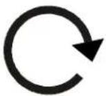 | Tighten Fastener |
| Apretar elemento de fijación | |
| Befestigungsteil festziehen | |
| Apertar fixador | |
| Serrare il fissaggio | |
| Bevestiging vastdraaien | |
| Serrez les fixations | |
 | Loosen Fastener |
| Aflojar elemento de fijación | |
| Befestigungsteil lösen | |
| Desapertar fixador | |
| Allentare il fissaggio | |
| Bevestiging losdraaien | |
| Desserrez les fixations | |
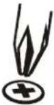 | Phillips Screwdriver |
| Destornillador Phillips | |
| Kreuzschlitzschraubendreher | |
| Chave de fendas Phillips | |
| Cacciavite a stella | |
| Kruiskopschroevendraaier | |
| Tournevis à pointe cruciforme | |
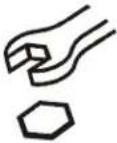 | Open-Ended Wrench |
| Llave de boca | |
| Gabelschlüssel | |
| Chave de bocas | |
| Chiave a punte aperte | |
| Steeksleutel | |
| Clé à fourche | |
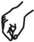 | By Hand |
| A mano | |
| Von Hand | |
| Com a mão | |
| A mano | |
| Met de hand | |
| À la main | |
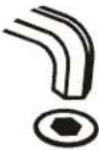 | Hex-Head Wrench |
| Llave de cabeza hexagonal | |
| Sechskantschlüssel | |
| Chave de cabeça sextavada | |
| Chiave esagonale | |
| Zeskantsleutel | |
| Clé à tête hexagonale |





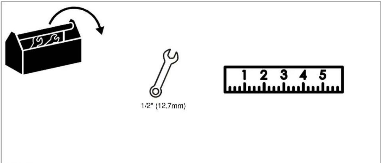
TOOLS REQUIRED FOR INSTALLATION
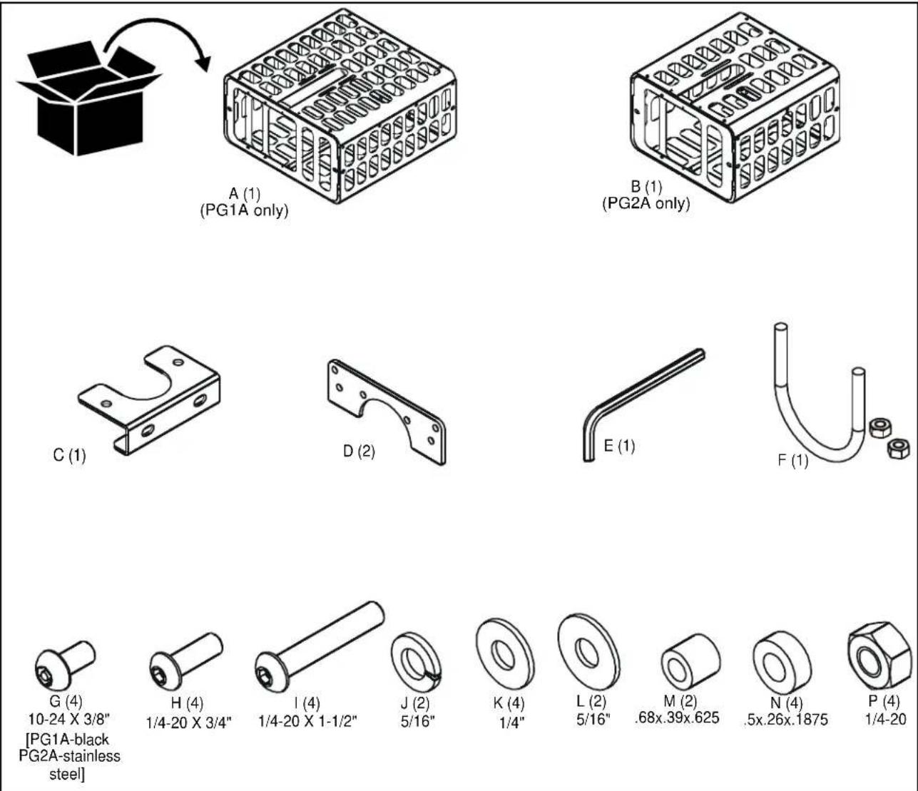
PARTS
Assembly And Installation
NOTE: The PG1A and PG2A should not be used in a flush ceiling mount.
NOTE: The projector must be removed from the mount before installing this accessory.
Removing Projector from Ceiling Mount
- Power off the projector and disconnect the power cord.
- Disconnect any audio/video cables from the projector.
- Loosen the thumbnails securing the projector to the RPA/RPM mount. (See Figure 1)
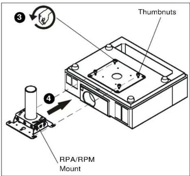
Figure 1
- Carefully slide the projector forward until it disengages from the RPA/RPM mount.
Attaching Interface Bracket to RPM/RPA
- For the RPM only, prepare two interface brackets (D) using four 1/4-20X3/4" buttonhead screws (H), four 1/4" flat washers (K) and four 1/4" hex nuts (P). (See Figure 2)
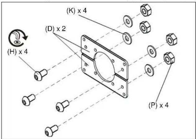
Figure 2
- Attach two interface brackets (D) to RPM using four 1/4-20 x 1-1/2" buttonhead cap screws (I) and four nylon spacers (N). (See Figure 3)
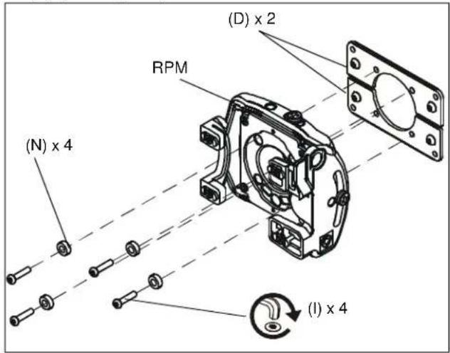
Figure 3
- For the RPA only attach two interface brackets (D) to the RPA using four 1/4-20x3/4" buttonhead screws (H), four 1/4" flat washers (K) and four 1/4" hex nuts (P). (See Figure 4)
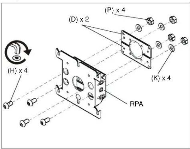
Figure 4
Configure Fillers on the Projector Guard
NOTE: The open cutout in the projector guard is designated as the FRONT of the guard.
- Remove and keep the security screws from the top and bottom of the front except for the two screws on the right side of the projector guard. (See Figure 5)
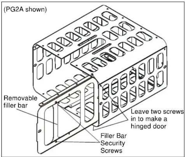
Figure 5
- Place projector inside the projector guard (See Figure 5)
NOTE: The front fillers serve two different purposes, and the number of fillers varies between the PG-1A and PG-2A. The front filler(s) can be installed to accommodate the various projector lens positions.
- Check the position of the front filler(s) to ensure the projector lens is unobstructed.
- To move the filler(s), remove the two security screws from each filler.
- Change the filler(s) position as necessary, and reinstall the security screws.
- Remove the projector from the projector guard.
Install Projector on RPA/RPM
- Ensure the SLB is installed on the projector. (See Figure 6) If the SLB needs to be installed, install it according to the installation instructions provided with the SLB.
- To connect the RPA to a new projector, refer to the installation instructions provided with the RPA.
- For a pole-mounted RPA, slide the slotted openings on the RPA into the threaded studs on the SLB. (See Figure 6) Fasten the RPA to the SLB with thumbnails and handtighten.
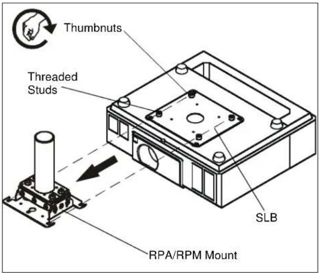
Figure 6
Install Projector Guard on Pole-Mounted Projector
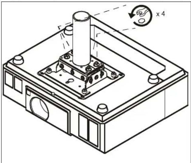
- Remove the four 1/4" flat washers (K) and four 1/4" hex nuts (P) from on top of the RPA/RPM mount. (See Figure 7)
natural_image
Technical line drawing of a mechanical assembly with a cylindrical component and mounting base (no text or symbols)Figure 7
- Slide the projector guard (A or B) into position over the projector, while aligning the slots on the projector guard with the screws in the RPA/RPM mount. (See Figure 8)
- Align the projector to sit evenly in the projector guard (A or B).
- Reinstall the 1/4" hex nuts (P) and 1/4" washers (K) onto the screws (H). (See Figure 8)
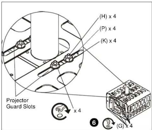
Figure 8
- Close the hinged door on the projector guard and reinstall the two security screws which were removed in Step 1 of Configure Fillers on the Projector Guard.
- Install four 10-24x3/8" security screws (G) in remaining four holes. (See Figure 8)
NOTE: A padlock may be placed on the projector guard for added security. (See Figure 9)
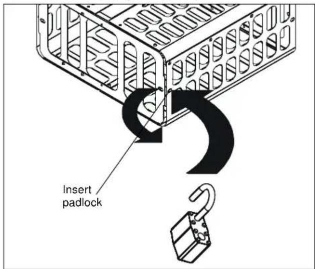
Figure 9
Install Projector Guard Using a Pipe Clamp
NOTE: Installation using a 1" or 1-1/2" diameter Schedule 40 steel pipe with 1-1/2" NPT threads requires securing the pipe to the building structure. We suggest using a CMA ceiling plate to secure the pipe to a structural member.
-
Using the projector, security mount and NPT pipe, determine the height location to install the locking collar (top of security mount).
-
Install the clamp and fasteners as follows:
a. For 1-1/2" NPT install the clamp at the desired height and secure using the U-bolt, two flat washers, two lock washers, and two 5/16-18 hex nuts (provided with U-bolt). (See Figure 10)
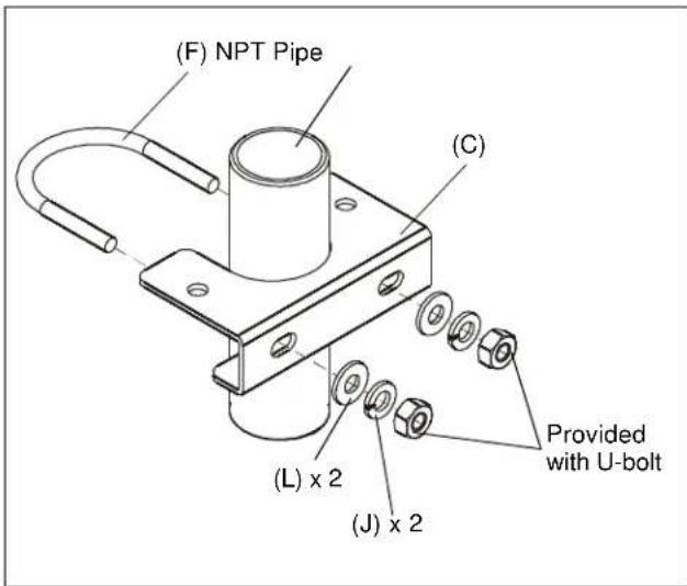
Figure 10
b. For 1" NPT install the clamp at the desired height and secure using the U-bolt, two nylon spacers, two flat washers, and two 5/16-19 hex nuts (provided with U-bolt). (See Figure 11)
- Install the projector on the 1" or 1-1/2" NPT pipe.
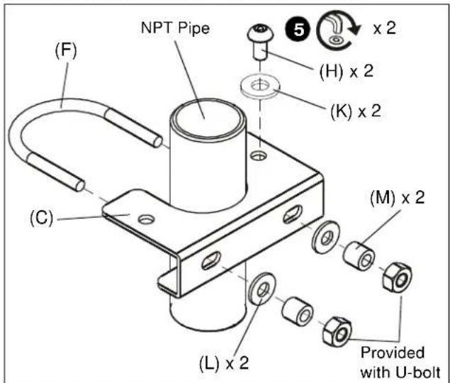
Figure 11
- Slide the projector guard over the clamp assembly and select the desired mounting slots in the projector guard.
- Secure the projector guard to the clamp using two 1/4-20 x 3/4" buttonhead screws and two flat washers. (See Figure 11)
NOTE: A padlock may be placed on the projector guard for added security. (See Figure 9)


- INSTALLATION INSTRUCTIONS
- Projector Guard Security Cage
- DISCLAIMER
- IMPORTANT WARNINGS AND TIONS!
- Assembly And Installation
- Removing Projector from Ceiling Mount
- Attaching Interface Bracket to RPM/RPA
- Configure Fillers on the Projector Guard
- Install Projector on RPA/RPM
- Install Projector Guard on Pole-Mounted Projector
- Install Projector Guard Using a Pipe Clamp
Brand : Chief
Model : PG1A
Category : Projector Accessories