
CMA347 - Projector Accessories Chief - Free user manual and instructions
Find the device manual for free CMA347 Chief in PDF.


| Product Type | Vibration Damper Mount for Projector |
| Brand | Chief |
| Model | CMA347 |
| Category | Projector Accessories |
| Weight Capacity | 35 lbs (15.88 kg) maximum; adjustable for loads under 15 lbs or over 15 lbs |
| Height (Max) | 30.86 in (783.7 mm) |
| Width | 15.00 in (381 mm) |
| Depth | 9.94 in (252.4 mm) |
| Mounting Interface | NPT 1 1/2" pipe thread (upper and lower) |
| Vibration Damping | Sorbothane dampers and springs (configurable) |
| Included Hardware | 1x CMA347 mount, 3x 1/4" flat washers, 2x 10-24 x 1/4" socket head set screws, 6x vibration bushings, 3x springs, 1x 3/32" hex key |
| Tools Required | 1/2" open-end wrench, 3/32" hex key (included) |
| Material | Steel |
| Color | Black |
| Installation Type | Ceiling mount (ceiling plate not included) |
| Application | Projector vibration isolation in suspended ceiling installations |
| Safety Notes | Ensure structure supports 5x equipment weight; do not exceed 35 lbs; use only as instructed |
| Compliance | Not specified (follow local building codes) |
| Warranty | See manufacturer (typical 5 years) |
| Manual Languages | English (PDF available) |
Frequently Asked Questions - CMA347 Chief
User questions about CMA347 Chief
0 question about this device. Answer the ones you know or ask your own.
Ask a new question about this device
Download the instructions for your Projector Accessories in PDF format for free! Find your manual CMA347 - Chief and take your electronic device back in hand. On this page are published all the documents necessary for the use of your device. CMA347 by Chief.
USER MANUAL CMA347 Chief
INSTALLATION INSTRUCTIONS
natural_image
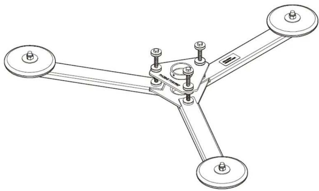
Technical line drawing of a three-legged robotic arm with mounting flanges and bolts (no text or symbols)Vibration Damper Mount
DISCLAIMER
Milestone AV Technologies and its affiliated corporations and subsidiaries (collectively "Milestone"), intend to make this manual accurate and complete. However, Milestone makes no claim that the information contained herein covers all details, conditions or variations, nor does it provide for every possible contingency in connection with the installation or use of this product. The information contained in this document is subject to change without notice or obligation of any kind. Milestone makes no representation of warranty, expressed or implied, regarding the information contained herein. Milestone assumes no responsibility for accuracy, completeness or sufficiency of the information contained in this document.
Chief® is a registered trademark of Milestone AV Technologies. All rights reserved.

IMPORTANT WARNINGS AND
CAUTIONS!

WARNING: A WARNING alerts you to the possibility of serious injury or death if you do not follow the instructions.

CAUTION: A CAUTION alerts you to the possibility of damage or destruction of equipment if you do not follow the corresponding instructions.

WARNING: Failure to read, thoroughly understand, and follow all instructions can result in serious personal injury, damage to equipment, or voiding of factory warranty! It is the installer's responsibility to make sure all components are properly assembled and installed using the instructions provided.

WARNING: Failure to provide adequate structural strength for this component can result in serious personal injury or damage to equipment! It is the installer's responsibility to make sure the structure to which this component is attached can support five times the combined weight of all equipment. Reinforce the structure as required before installing the component.

WARNING: Exceeding the weight capacity can result in serious personal injury or damage to equipment! It is the installer's responsibility to make sure the combined weight of all components located between the CMA-347 up to (and including) the display/projector does not exceed 35 lbs (15.88 kg). Use with products heavier than the maximum weight indicated may result in collapse of the mount and its accessories causing possible injury.
- SAVE THESE INSTRUCTIONS-
DIMENSIONS
![27.38 [695.3] 15.00 [381] 9.94 [252.4] 30.86 [783.7] 1.78 [45.3] 2.00 [50.8] 1-1/2" PIPE THREAD 2.97 [75.4] DIMENSIONS: INCHES [MILLIMETERS]](/content/2026/05/795102/images/a937da383838ea311446c4ed977b9641f4a3237bee3275a50a1171c746644d0c.jpg)
LEGEND
 | Tighten Fastener |  | Open-Ended Wrench |
| Apretar elemento de fijación | Llave de boca | ||
| Befestigungsteil festziehen | Gabelschlüssel | ||
| Apertar fixador | Chave de bocas | ||
| Serrare il fissaggio | Chiave a punte aperte | ||
| Bevestiging vastdraaien | Steeksleutel | ||
| Serrez les fixations | Clé à fourche | ||
 | Loosen Fastener |  | Hex-Head Wrench |
| Aflojar elemento de fijación | Llave de cabeza hexagonal | ||
| Befestigungsteil lösen | Sechskantschlüssel | ||
| Desapertar fixador | Chave de cabeça sextavada | ||
| Allentare il fissaggio | Chiave esagonale | ||
| Bevestiging losdraaien | Zeskantsleutel | ||
| Desserrez les fixations | Clé à tête hexagonale |
TOOLS REQUIRED FOR INSTALLATION
| 19/31 |
| 1/2" |
| 3/32" (included) |
PARTS
 | |
| A (1) [CMA347 mount] | |
| B (3) [1/4"] | |
| C (2) [10-24 x 1/4"] | |
| D (6) [Vibration bushing] | |
| E (3) [Spring] | |
| F (1) 3/32" | |
PREPARATION AND INSTALLATION
NOTE: The following instructions assume that a suitable ceiling plate (not included) has been properly installed following instructions included with the ceiling plate.
NOTE: Keep the CMA347 as close as possible to the projector by minimizing the length of the lower mounting pipe.
IMPORTANT ! : The mount is shipped pre-assembled for applications under 15 lbs.

CAUTION: WEIGH ALL PARTS BEFORE BEGINNING
INSTALLATION! If the total combined weight of the projector, projector mount, and lower mounting pipe exceeds 15 lbs, the CMA347 vibration mount MUST be reconfigured before proceeding with the installation.
IMPORTANT ! : Proceed to the appropriate section to complete installation:
• CMA347 Installation section (for installations of 15 lbs or less),
• Set-Up CMA347 for Over 15 lbs section, or
- Change CMA347 from Over 15 lbs to 15 lbs or Less section
CMA347 Installation
- Thread NPT 1 1/2" upper mounting pipe (not included) into ceiling plate (not included). (See Figure 1)
- Secure NPT 1 1/2" upper mounting pipe to ceiling plate following the installation instructions provided with the ceiling plate (not included). (See Figure 1)
- Thread top of CMA347 mount (A) onto NPT 1 1/2" upper mounting pipe. (See Figure 1)
NOTE: Ensure there is no direct contact between mount and surrounding structure. Any contact could allow vibration transfer to the projector.
4. Secure NPT 1 1/2" upper mounting pipe to CMA347 mount (A) using one 10-24 x 1/4" socket head set screw (C). Turn set screw (C) until it contacts thread of NPT 1 1/2" upper mounting pipe. (See Figure 1)
5. Thread NPT 1 1/2" lower mounting pipe (not included) into bottom of CMA 347 mount (A). (See Figure 1)
6. Secure NPT 1 1/2" lower mounting pipe to CMA347 mount (A) using one 10-24 x 1/4" socket head set screw (C). Turn set screw (C) until it contacts thread of NPT 1 1/2" lower mounting pipe. (See Figure 1)
7. Thread projector mount (not included) onto lower NPT 1 1/2" lower mounting pipe. (See Figure 1)
8. Secure NPT 1 1/2" lower mounting pipe to projector mount following the installation instructions provided with the projector mount (not included). (See Figure 1)
9. Attach projector to projector mount following the installation instructions provided with the projector mount (not included).
10. With the weight of the installation on the CMA-347, tighten the 1/4-20" spring bolts until a slight preload is on the springs. (See Figure 1)
- Installation is complete for installations of 15 lbs or less.
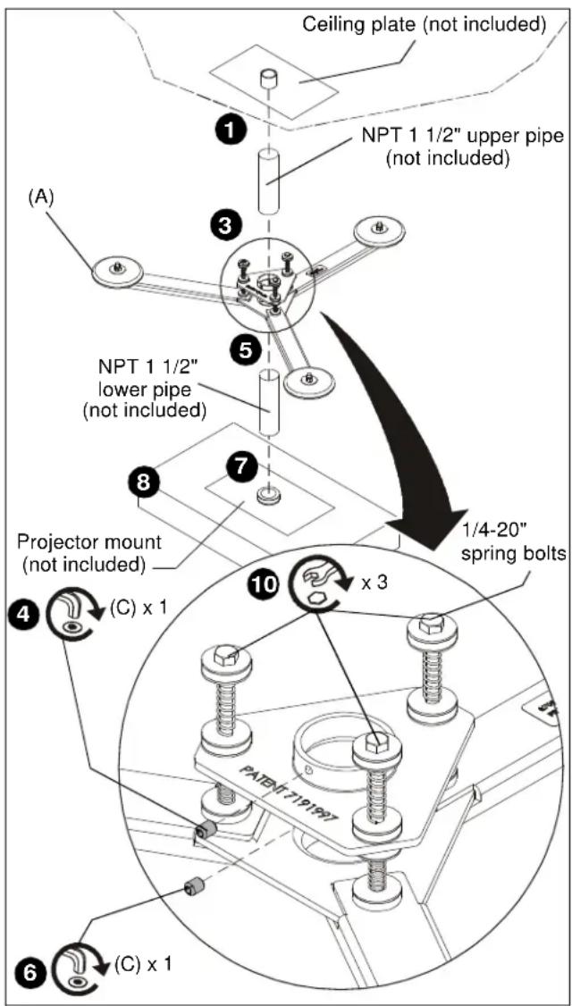
Figure 1
Set-Up CMA347 for Over 15 Pounds

WARNING: DO NOT attempt to reconfigure the mount while installed. If mount was previously installed for 15 lbs or less, properly un-install mount and place on a flat stable surface before performing the following procedure.
IMPORTANT ! : If required, un-install CMA347 following instructions Removing Mount section.
- Remove and SAVE 1/4-20 Nylock nut, 1/4" fender washer, and stepped sorbothane damper located underneath mount arm. (See Figure 7)
- Remove Group A hardware (and SAVE 1/4-20 spring bolt) by sliding 1/4-20 spring bolt upward. (See Figure 2)
NOTE: Make certain Group B hardware stays in place when removing 1/4-20 spring bolt and associated hardware. (See Figure 2)
- Install one 1/4" machine washer (B), two vibration bushings (D), and one long heavy gauge spring (E) onto 1/4-20 spring bolt. (See Figure 3)
- Insert 1/4-20 spring bolt with washers and bushings through mount top (A), Group B hardware, and mount bottom (A). (See Figure 3)
- Install stepped sorbothane damper, fender washer, and Nylock nut (removed in Step 1) onto 1/4-20 x 4" spring bolt from below mount bottom.
- Tighten all the parts installed in Steps 3, 4 and 5 until a slight preload is on the springs.
NOTE: Repeat Steps 1 through 6 for the remaining two hardware sets.
- Set-up is complete for installations over 15 lbs.
- Go to CMA347 Installation section (page 4) to complete installation.
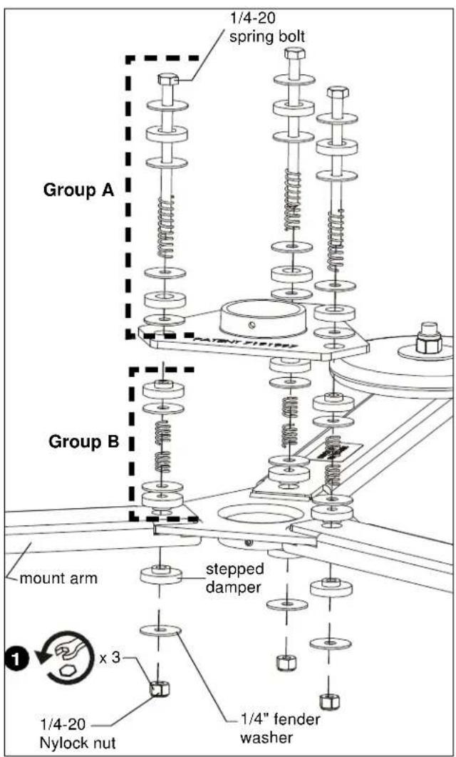
Figure 2
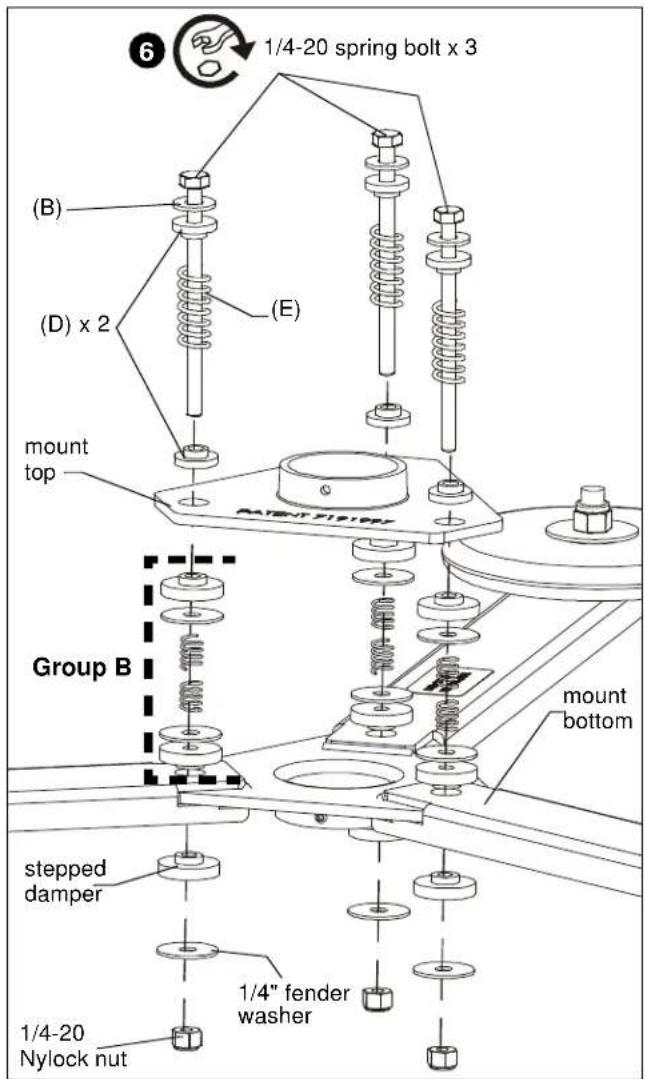
Figure 3
Change CMA347 from Over 15 lbs to 15 lbs or Less

WARNING: DO NOT attempt to reconfigure the mount while installed. If mount was previously installed for over 15 lbs, properly un-install mount and place on a flat stable surface before performing the following procedure.
IMPORTANT ! : If required, un-install CMA347 following instructions in Removing Mount section.
- Remove and SAVE 1/4-20 Nylock nut, 1/4" fender washer, and stepped sorbothane damper located underneath mount arm. (See Figure 4)
- Remove Group A hardware (and SAVE 1/4-20 spring bolt) by sliding 1/4-20 spring bolt upward. (See Figure 4)
NOTE: Make certain Group B hardware stays in place when removing 1/4-20 spring bolt and associated hardware. (See Figure 4)
- Install four 1/4" fender washers, two sorbothane dampers, and one long medium gauge spring (removed when mount was changed to over 15 lbs configuration), onto 1/4-20 x 4" spring bolt. (See Figure 5)
- Insert 1/4-20 spring bolt with washers and dampers through mount top (A), Group B hardware, and mount bottom (A). (See Figure 3)
- Install stepped sorbothane damper, fender washer, and Nylock nut (removed in Step 1) onto 1/4-20 x 4" spring bolt from below mount bottom.
- Tighten all the parts installed in Steps 3, 4 and 5 until a slight preload is on the springs.
NOTE: Repeat Steps 1 through 6 for the remaining two hardware sets.
- Changeover from an installation over 15 lbs to an installation of 15 lbs or less is complete.
- Go to CMA347 Installation section (page 4) to complete installation.
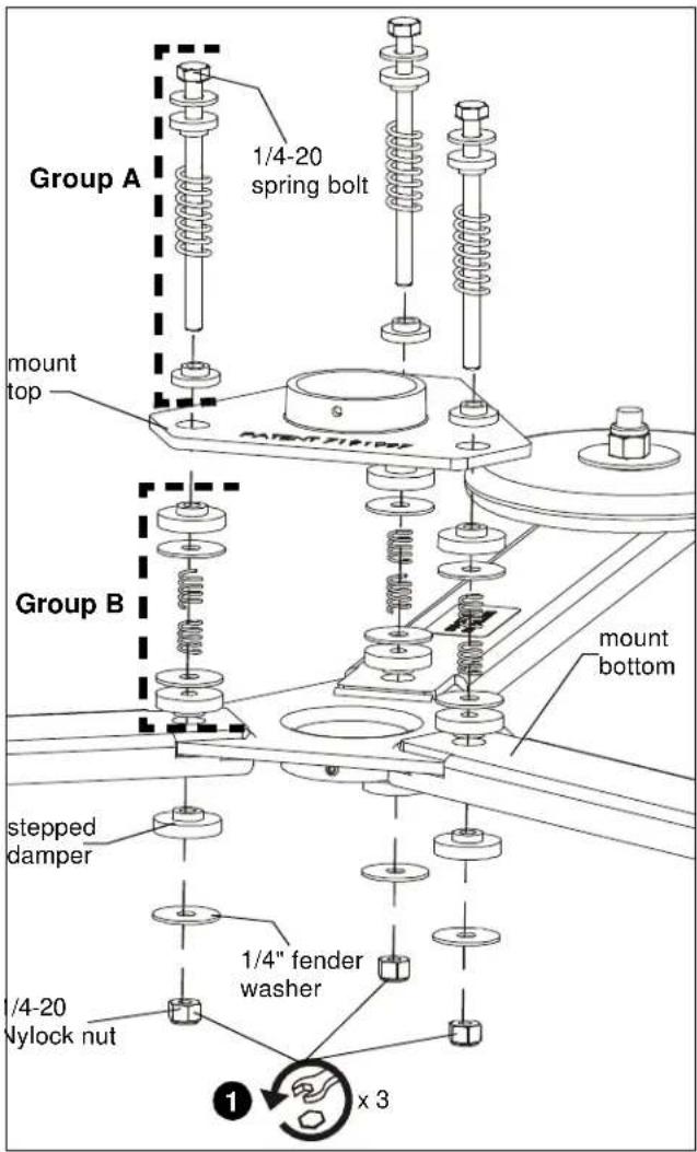
Figure 4
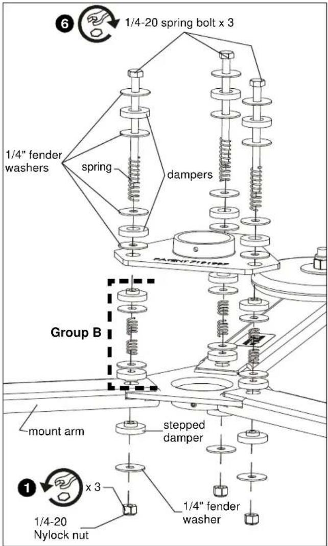
Figure 5
Mount Removal
- Disconnect power cables and wires from projector.
- Uninstall projector from projector mount. (See Figure 6)
- Uninstall projector mount from NPT 1 1/2" lower mounting pipe following the instructions provided with the projector mount. (See Figure 6)
- Loosen 5/16-18 x 3/8" socket head set screw securing NPT 1 1/2" lower mounting pipe to mount bottom. (See Figure 6)
- Uninstall NPT 1 1/2" lower mounting pipe from mount bottom by turning NPT 1 1/2" lower mounting pipe counterclockwise. (See Figure 6)
- Loosen 5/16-18 x 3/8" socket head set screw (C) securing mount top (A) to NPT 1 1/2" upper mounting pipe. (See Figure 6)
- Uninstall CMA347 from NPT 1 1/2" upper mounting pipe by turning mount top (A) counterclockwise. (See Figure 6)
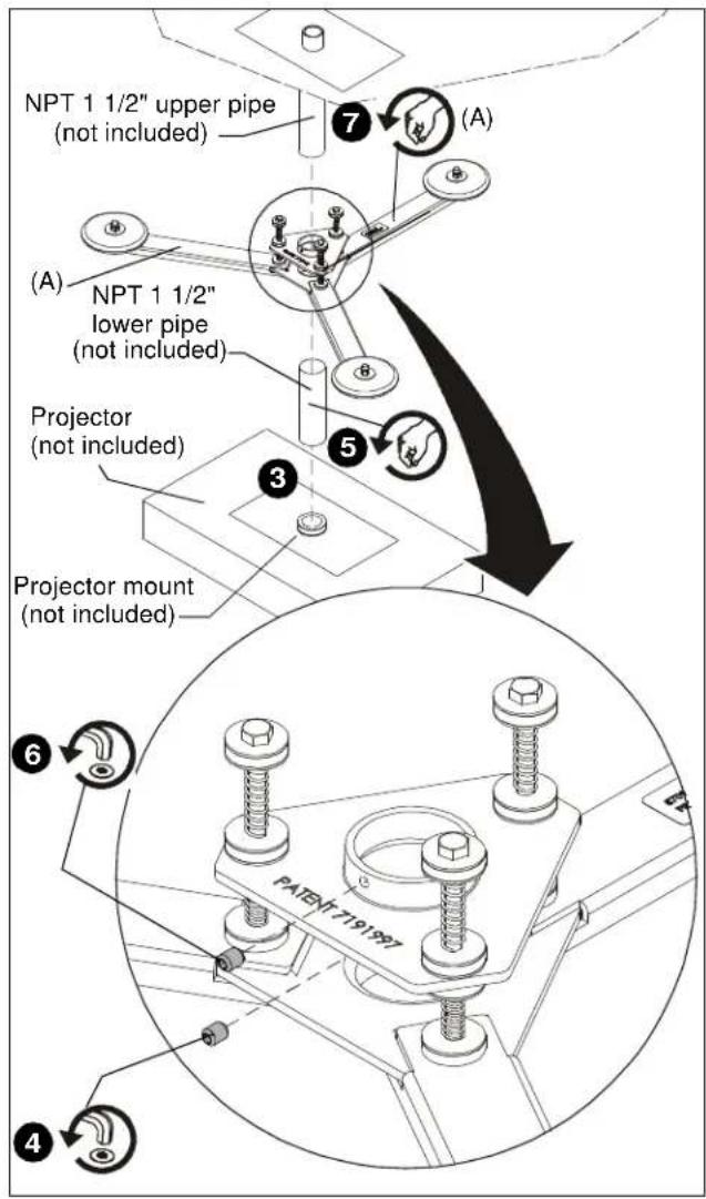
Figure 6
Installation Instructions


Brand : Chief
Model : CMA347
Category : Projector Accessories