
RCP-920 - Remote control SONY - Free user manual and instructions
Find the device manual for free RCP-920 SONY in PDF.


| Product Type | Remote Control Panel |
| Brand | Sony |
| Model | RCP-920 |
| Application | Professional Camera Control (e.g., HDC series) |
| Dimensions (W x H x D) | 210 mm x 90 mm x 45 mm |
| Weight | Approximately 500 g |
| Power Supply | 12 V DC (4-pin XLR connector) |
| Power Consumption | 10 W maximum |
| Control Functions | Iris, Gain, White Balance, Black Level, Master Pedestal, Paint, etc. |
| User Interface | Joystick, assignable buttons, LCD display, rotary encoders |
| Communication Interface | RS-422 or RS-485 (via D-sub 9-pin) |
| Cable Length | Up to 100 m (with appropriate cable) |
| Mounting | Desktop or rack-mountable with optional kit |
| Operating Temperature | 0°C to 40°C |
| Storage Temperature | -20°C to 60°C |
| Cleaning | Use a soft, dry cloth. Avoid solvents. |
| Safety | Use only specified power supply; do not expose to moisture. |
| Spare Parts & Repairability | Contact Sony authorized service center for parts and repairs. |
| Manual | 80-page PDF available for download. |
| Warranty | Standard Sony warranty applies; check documentation. |
Frequently Asked Questions - RCP-920 SONY
User questions about RCP-920 SONY
0 question about this device. Answer the ones you know or ask your own.
Ask a new question about this device
Download the instructions for your Remote control in PDF format for free! Find your manual RCP-920 - SONY and take your electronic device back in hand. On this page are published all the documents necessary for the use of your device. RCP-920 by SONY.
USER MANUAL RCP-920 SONY
natural_image
Technical line drawing of a rectangular electronic enclosure with mounting flanges and a central component (no text or symbols)natural_image
Technical line drawing of a rectangular electronic device with mounting flanges and a screw inserted (no text or symbols)各部の名称と働き
操作パネル

①液晶画面
調整項目などを表示します。
②CLEAR(クリア)ボタン
3 TCP/IP 関連の設定をする。
設定できる項目は、以下のとおりです。
5 TCP/IP 設定を保存する。
For the customers in the U.S.A.
This equipment has been tested and found to comply with the limits for a Class A digital device, pursuant to Part 15 of the FCC Rules. These limits are designed to provide reasonable protection against harmful interference when the equipment is operated in a commercial environment. This equipment generates, uses, and can radiate radio frequency energy and, if not installed and used in accordance with the instruction manual, may cause harmful interference to radio communications. Operation of this equipment in a residential area is likely to cause harmful interference in which case the user will be required to correct the interference at his own expense.
You are cautioned that any changes or modifications not expressly approved in this manual could void your authority to operate this equipment.
All interface cables used to connect peripherals must be shielded in order to comply with the limits for a digital device pursuant to Subpart B of Part 15 of FCC Rules.
For the customers in Europe
This product with the CE marking complies with the EMC Directive issued by the Commission of the European Community.
Compliance with this directive implies conformity to the following European standards:
• EN55103-1: Electromagnetic Interference (Emission)
• EN55103-2: Electromagnetic Susceptibility (Immunity)
This product is intended for use in the following Electromagnetic Environments: E1 (residential), E2 (commercial and light industrial), E3 (urban outdoors), E4 (controlled EMC environment, ex. TV studio).
For the customers in Europe
The manufacturer of this product is Sony Corporation, 1-7-1 Konan, Minato-ku, Tokyo, Japan.
The Authorized Representative for EMC and product safety is Sony Deutschland GmbH, Hedelfinger Strasse 61, 70327 Stuttgart, Germany. For any service or guarantee matters please refer to the addresses given in separate service or guarantee documents.
For the State of California, USA only
Perchlorate Material - special handling may apply, See www.dtsc.ca.gov/hazardouswaste/perchlorate Perchlorate Material : Lithium battery contains perchlorate.
For the customers in Taiwan only

廢電池請回收
Table of Contents
Precautions.... 43
Overview 43
Features....43
Examples of System Configurations ....45
Precautions for Ethernet System Connections....47
Location and Function of Parts 48
Operation Panel ....48
Connector Panel....55
Menu Configuration and Basic Operation 56
Basic operation ....56
Basic configuration of menu pages ....57
Menu transition diagram....59
Menu Items 60
Initial Settings.... 65
Configuring the RCP-920/921 Operating Environment......65
Adjusting the LCD Display 76
Specifications 76
Precautions
Note on faulty pixels on the LCD panel
The LCD panel fitted to this unit is manufactured with high precision technology, giving a functioning pixel ratio of at least 99.99%. Thus a very small proportion of pixels may be “stuck,” either always off (black), always on (red, green, or blue), or flashing. In addition, over a long period of use, because of the physical characteristics of the liquid crystal display, such “stuck” pixels may appear spontaneously. These problems are not a malfunction.
Overview
Features
The RCP-920/921 Remote Control Panel is designed for remote control of the BVP/HDC series Color Video Camera via the CCU/HDCU Camera Control Unit. This panel is connected to the CCU/HDCU Camera Control Unit (or the CNU-700 Camera Command Network Unit, which is connected to the CCU/HDCU) by a dedicated cable of up to 200 m (656 feet) in length and controls the camera functions which are used most frequently in basic applications from a distance.
The RCP-920 and RCP-921 are completely identical in their functions except with respect to the iris and master black adjustments.
For the iris and master black adjustments, the RCP-920 uses a joystick type control while the RCP-921 uses rotary knobs.
The principal features of the RCP-920/921 are as follows.
Optimized control arrangement for basic camera operation
This remote control panel is provided with essential control functions for basic operation of a BVP/HDC-series camera.
The buttons, knobs, and other controls have been arranged according to their functions and with consideration to their frequency of use. Indicators and buttons light or flash to indicate the status of the system operation.
Also, guard frames are provided to protect against accidental use of those buttons vital to camera operation. These features ensure easy and error-free use of this remote control panel.
Auto setup control
The RCP-920/921 has built-in microcomputers that reliably perform automatic setup for the majority of the control items. The various items can be automatically adjusted independently or in combination.
Scene file control
Using the paint menu, camera adjustment data for a particular scene can be stored in the video camera as a scene file. Up to five such files can be stored. This allows quick adaptation to various shooting conditions simply by calling up a scene file.
Camera SLS/ECS/shutter function control
The SLS (Slow Shutter), ECS (Extended Clear Scan), and electronic shutter functions of the camera can be turned ON/OFF from this panel. The ECS frequency and shutter speed are also selected using the buttons on the panel.
Dedicated cable or Ethernet connection
The connection between the remote control panel and the camera control unit is established by a single dedicated cable (CCA-5) that reliably sends and receives all necessary signals and also provides power for the panel. Alternatively, a connection via Ethernet cable is also possible.
Support for parallel operation with other control panels
Video cameras can be concurrently controlled from this panel and other controller, such as the MSU-900/950 Master Setup Unit.
Four units fit in 19-inch rack
Up to four units of this control panel can be mounted in line on a 19-inch EIA standard rack.
Examples of System Configurations
Command cable system (for HDC series)

flowchart
graph TD
    subgraph_HDC1000["HDC1000"]
        A1["or"] --> B1["HDCU1500(+HKCU1001/HKCU1003)"]
        A2["or"] --> B2["HDCU1000(+HKCU1001/HKCU1003)"]
        A3["or"] --> B3["HDCU1500(+HKCU1001/HKCU1003)"]
        A4["or"] --> B4["HDCU1500(+HKCU1001/HKCU1003)"]
    end

    subgraph_HDC1000["HDC1000"]
        B1 --> C1["HDCU1500(+HKCU1001/HKCU1003)"]
        B2 --> C2["HDCU1500(+HKCU1001/HKCU1003)"]
        B3 --> C3["HDCU1500(+HKCU1001/HKCU1003)"]
        B4 --> C4["HDCU1500(+HKCU1001/HKCU1003)"]
    end

    subgraph_HDC1500["HDC1500"]
        C1 --> D1["or"]
        C2 --> D2["or"]
        C3 --> D3["or"]
        C4 --> D4["or"]
    end

    subgraph_HDC1500["HDC1500"]
        D1 --> E1["or"]
        D2 --> E2["or"]
        D3 --> E3["or"]
        D4 --> E4["or"]
    end

    subgraph_HDC1500["HDC1500"]
        E1 --> F1["HDCU1500(+HKCU1001/HKCU1003)"]
        E2 --> F2["HDCU1500(+HKCU1001/HKCU1003)"]
        E3 --> F3["HDCU1500(+HKCU1001/HKCU1003)"]
    end

    subgraph_HDC1500["HDC1500"]
        F1 --> G1["or"]
        F2 --> G2["or"]
        F3 --> G3["or"]
    end

    subgraph_HDC1500["HDC1500"]
        G1 --> H1["or"]
        G2 --> H2["or"]
        G3 --> H3["or"]
    end

    subgraph_HDC1500["HDC1500"]
        H1 --> I1["or"]
        H2 --> I2["or"]
        H3 --> I3["or"]
    end

    subgraph_HDC1500["HDC1500"]
        I1 --> J1["or"]
        I2 --> J2["or"]
        I3 --> J3["or"]
    end

    subgraph_HDC1500["HDC1500"]
        J1 --> K1["HDCU1500(+HKCU1001/HKCU1003)"]
        J2 --> K2["HDCU1500(+HKCU1001/HKCU1003)"]
    end

    subgraph_HDC1500["HDC1500"]
        K1 --> L1["or"]
        K2 --> L2["or"]
        K3 --> L3["or"]
    end

    subgraph_HDC1500["HDC1500"]
        L1 --> M1["or"]
        L2 --> M2["or"]
        L3 --> M3["or"]
    end

    subgraph_HDC1500["HDC1500"]
        M1 --> N1["or"]
        M2 --> N2["or"]
        M3 --> N3["or"]
    end

    subgraph_HDC1500["HDC1500"]
        N1 --> O1["or"]
        N2 --> O2["or"]
        N3 --> O3["or"]
    end

    subgraph_HDC1500["HDC1500"]
        O1 --> P1["or"]
        O2 --> P2["or"]
        O3 --> P3["or"]
    end

    subgraph_HDC1556["HDC1556"]
        P1 --> Q["VCS-700"]
        P2 --> Q
        P3 --> Q
    end

    subgraph_HDC768["RCP-920/921"]
        Q --> R["CCU-768 RCP-920/921"]
    end

    subgraph_HDC768["RCP-920/921"]
        R --> S["CCU-768 RCP-920/921"]
    end

    subgraph_HDC768["RCP-920/921"]
        S --> T["CCU-768 RCP-920/921"]
    end

    subgraph_HDC768["RCP-920/921"]
        T --> U["CCU-768 RCP-920/921"]
    end

    subgraph_HDC768["RCP-920/921"]
        U --> V["CCU-768 RCP-920/921"]
    end

    subgraph_HDC768["RCP-920/921"]
        V --> W["CCU-768 RCP-920/921"]
    end

    subgraph_HDC768["RCP-920/921"]
        W --> X["CCU-768 RCP-920/921"]
    end

    subgraph_HDC768["RCP-920/921"]
        X --> Y["CCU-768 RCP-920/921"]
    end

    subgraph_HDC768["RCP-920/921"]
        Y --> Z["CCU-768 RCP-920/921"]
    end

    subgraph_HDC768["RCP-920/921"]
        Z --> AA["CCU-768 RCP-920/921"]
    end

    subgraph_HDC768["RCP-920/921"]
        AA --> AB["CCU-768 RCP-920/921"]
    end

    subgraph_HDC768["RCP-920/921"]
        AB --> AC["CCU-768 RCP-920/921"]
    end

    subgraph_HDC768["RCP-920/921"]
        AC --> AD["CCU-768 RCP-920/921"]
    end

    subgraph_HDC768["RCP-920/921"]
        AD --> AE["CCU-768 RCP-920/921"]
    end

    subgraph_HDC768["RCP-920/921"]
        AE --> AF["CCU-768 RCP-920/921"]
    end

    subgraph_HDC768["RCP-920/921"]
        AF --> AG["CCU-768 RCP-920/921"]
    end

    subgraph_HDC768["RCP-920/921"]
        AG --> AH["CCU-768 RCP-920/921"]
    end

    subgraph_HDC768["RCP-92O/92I"]
        AH --> AI["CCU-CNU REMOTE"]
        AI --> AJ["CCU-CNU REMOTE"]
        AJ --> AK["CCU-CNU REMOTE"]
        AK --> AL["CPU-CNU REMOTE"]
        AL --> AM["CPU-CNU REMOTE"]

    end

    subgraph_HDC768["RCP-92O/92I"]
        AI --> AN["CCA-5 cable"]

    subgraph_HDC768["RCP-92O/92I"]
        AN --> AO["CCA-5 cable"]

    subgraph_HDC768["RCP-92O/92I"]
        AO --> AP["CCA-5 cable"]

    subgraph_HDC768["RCP-92O/92I"]
        AP --> AQ["CCA-5 cable"]

    subgraph_HDC768["RCP-92O/92I"]
        AQ --> AR["CCA-5 cable"]

    subgraph_HDC768["RCP-92O/92I"]
        AR --> AS["CCA-5 cable"]

    subgraph_HDC768["RCP-92O/92I"]
        AS --> AT["CCA-5 cable"]

    subgraph_HDC768["RCP-92O/92I"]
        AT --> AU["CCA-5 cable"]

    subgraph_HDC768["RCP-92O/92I"]
        AU --> AV["CCA-5 cable"]

    subgraph_HDC768["RCP-92O/92I"]
        AV --> AW["CCA-5 cable"]

    subgraph_HDC768["RCP-92O/92I"]
        AW --> AX["CCA-5 cable"]

    subgraph_HDC768["RCP-92O/92I"]
        AX --> AY["CCA-5 cable"]

    subgraph_HDC768["RCP-92O/92I"]
        AY --> AZ["CCA-5 cable"]

    subgraph_HDC768["RCP-92O/92I"]
        AZ --> BA["CCA-5 cable"]

    subgraph_HDC768["RCP-92O/92I"]
        BA --> BB["CCA-5 cable"]

    subgraph_HDC768["RCP-92O/92I"]
        BB --> BC["CCA-5 cable"]

    subgraph_HDC768["RCP-92O/92I"]
        BC --> BD["CCA-5 cable"]

    subgraph_HDC768["RCP-92O/92I"]
        BD --> BE["CCA-5 cable"]

    subgraph_HDC768["RCP-92O/92I"]
        BE --> BF["CCA-5 cable"]

    subgraph_HDC768["RCP-92O/92I"]
        BF --> BG["CCA-5 cable"]

    subgraph_HDC768["RCP-92O/92I"]
        BG --> BH["CCA-5 cable"]

    subgraph_HDC768["RCP-92O/92I"]
        BH --> BI["CCA-5 cable"]

    subgraph_HDC768["RCP-92O/92I"]
        BI --> BJ["CCA-5 cable"]

    subgraph_HDC768["RCP-92O/92I"]
        BJ --> BK["CCA-5 cable"]

    subgraph_HDC768["RCP-92O/92I"]
        BK --> BL["CCA-5 cable"]

    subgraph_HDC768["RCP-92O/92I"]
        BL --> BM["CCA-5 cable"]

    subgraph_HDC768["RCP-92O/92I"]
        BM --> BN["CCA-5 cable"]

    subgraph_HDC768["RCP-92O/92I"]
        BN --> BO["CCA-5 cable"]

    subgraph_HDC768["RCP-92O/92I"]
        BO --> BP["CCA-5 cable"]

    subgraph_HDC768["RCP-92O/92I"]
        BP --> BQ["CCA-5 cable"]

    subgraph_HDC768["RCP-92O/92I"]
        BQ --> BR["CCA-5 cable"]

    subgraph_HDC768["RCP-92O/92I"]
        BR --> BS["CCA-5 cable"]

    subgraph_HDC768["RCP-92O/92I"]
        BS --> BT["CCA-5 cable"]

    subgraph_HDC768["RCP-92O/92I"]
        BT --> BU["CCA-5 cable"]

    subgraph_HDC768["RCP-92O/92I"]
        BU --> BV["CCA-5 cable"]

    end

    style_HDC768["RCP-92O/92I"]
Ethernet system (for HDC series)
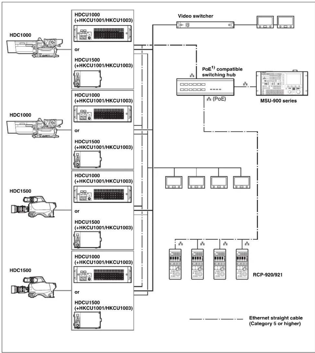
flowchart
graph TD
    A["HDC1000"] --> B["HDCU1000 (+HKCU1001/HKCU1003)"]
    B --> C["or"]
    B --> D["HDCU1500 (+HKCU1001/HKCU1003)"]
    D --> E["or"]
    F["HDC1000"] --> G["HDCU1000 (+HKCU1001/HKCU1003)"]
    G --> H["or"]
    G --> I["HDCU1500 (+HKCU1001/HKCU1003)"]
    I --> J["or"]
    K["HDC1500"] --> L["HDCU1000 (+HKCU1001/HKCU1003)"]
    L --> M["or"]
    L --> N["HDCU1500 (+HKCU1001/HKCU1003)"]
    N --> O["or"]
    P["HDC1500"] --> Q["HDCU1000 (+HKCU1001/HKCU1003)"]
    Q --> R["or"]
    Q --> S["HDCU1500 (+HKCU1001/HKCU1003)"]
    S --> T["or"]
    U["Video switcher"] --> V["PoE¹) compatible switching hub (PoE)"]
    V --> W["MSU-900 series"]
    W --> X["RCP-920/921"]
    X --> Y["Ethernet straight cable (Category 5 or higher)"]
1) Power over Ethernet
About the switching hub power supply
As the maximum power of the RCP-920/921 is 14 W, multiply 14 W by the number of connected RCP units when considering the power supply from the switching hub.
Precautions for Ethernet System Connections
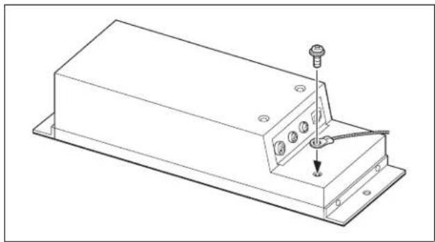
When connecting the unit to the system with an Ethernet cable, make sure to ground the unit using one of the following methods.
- Secure the flanges on the unit with screws.
- Connect a ground wire to the bottom of the unit.
To secure the flanges on the unit with screws

Note
The screws are not supplied with this unit. Use screws that are suited to the installation location.
To connect a ground wire to the bottom of the unit
1 Unscrew the screw on the rear of the unit.

natural_image
Technical line drawing of a rectangular electronic device with mounting flanges and a small component inserted (no text or symbols)2 Attach the ground wire with the removed screw.
natural_image
Technical line drawing of a rectangular electronic device with mounting base and internal components (no text or symbols)Location and Function of Parts
Operation Panel
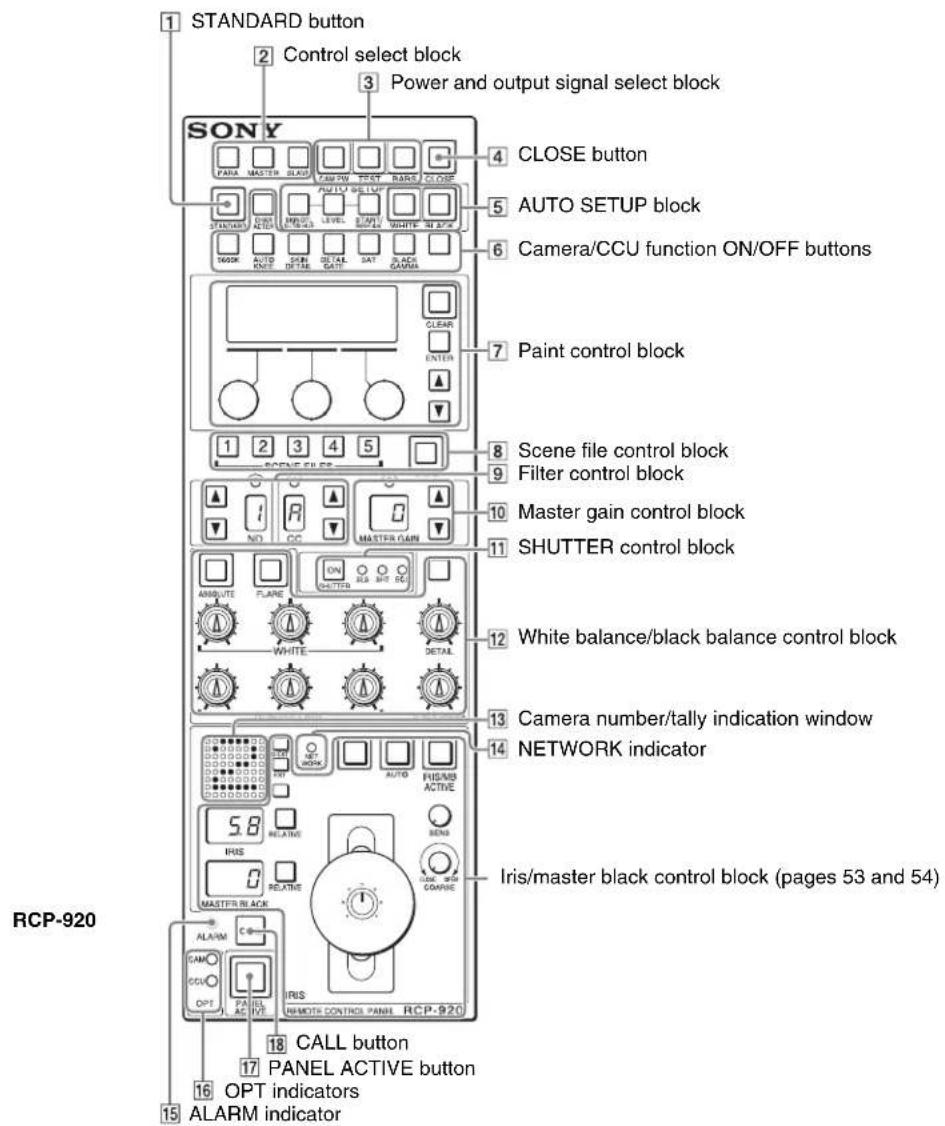
RCP-921

1 STANDARD button
When you press this button, the video camera settings are initialized to the reference values stored on the video camera, and the button lights for several seconds.
If you press the button while it lights, the video camera retrieves the state before the button was lit.
2 Control select block
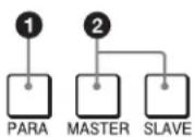
①PARA (parallel mode) button
Lights when Parallel mode is active, in which concurrent operation with another control panel is possible.
When this button is lit, all the buttons and controls on this panel except for the iris/master black control block and CLOSE button are active, even if the PANEL ACTIVE button is not lit.
If you press the button while lit, it goes dark and Parallel mode is cancelled.
②MASTER and SLAVE buttons
When adjusting the white balance of multiple cameras in Master/Slave mode, designate the master camera or the slave camera with these buttons.
Press and light up the MASTER button to specify the connected camera for the master. Press and light up the SLAVE button to specify the connected camera for the slave. The slave cameras follow the master camera settings.
If you press a button when lit, it goes dark.
3 Power and output signal select block
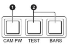
①CAM PW (camera power) button
Press and light up this button to turn the power supply to the video camera ON. (The button promptly flashes until the camera becomes ready for transmission.)
When you press this button again, it starts flashing and the power supply is turned OFF.
②Test signal output select buttons
Press and light up one of these buttons to activate the test signal generator of the video camera and send the respective signals.
TEST: To send a sawtooth signal to test the video circuits.
BARS: To send a color bar signal.
Note
The BARS button takes priority to the TEST button. If the BARS button is lit, press the button to turn it dark before pressing the TEST button.
4 CLOSE (iris close) button
Press and light up this button to close the iris. If you press the button while lit, it goes dark and iris closure is canceled.
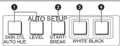
5 AUTO SETUP block
This block has various buttons for automatic adjustment of the camera.
flowchart
graph TD
    A["1"] --> B["SKIN DTL AUTO HUE"]
    C["2"] --> D["LEVEL"]
    E["3"] --> F["START/ BREAK"]
    G["4"] --> H["WHITE BLACK"]
    style A fill:#f9f,stroke:#333
    style C fill:#f9f,stroke:#333
    style E fill:#f9f,stroke:#333
    style G fill:#f9f,stroke:#333
① Auto adjustment item select buttons
Press and light up these buttons to select items to be automatically adjusted.
SKIN DTL AUTO HUE: Skin tone detail automatic hue
LEVEL: Gamma balance, knee point, master black level, etc.
②START/BREAK button
Press to start automatic adjustment of the selected items. The button lights during adjustment and goes dark when adjustment is completed.
If you press the button when lit, the automatic adjustment is cancelled and the button flashes. To stop the flashing, press the button again.
③WHITE (white balance) button
Press to automatically adjust the white balance.
The button lights during adjustment and goes dark when adjustment is completed.
If you press this button when lit or the START/BREAK button, the automatic adjustment is cancelled and the button flashes. To stop the flashing, press the button again.
④BLACK (black balance) button
Press to automatically adjust the black balance and black set.
The button lights during adjustment and goes dark when adjustment is completed.
If you press this button when lit or the START/BREAK button, the automatic adjustment is cancelled and the button flashes. To stop the flashing, press the button again.
Note
If an error occurs during adjustment, the pressed button flashes.
6 Camera/CCU function ON/OFF buttons
Various functions of the video camera or the CCU/HDCU can be turned ON and OFF from this panel.
The following switching functions are assigned to seven of the buttons at the factory and the rightmost button is reserved for future use.
Press and light up these buttons to turn ON the respective functions.
Press again so that the buttons go dark to turn OFF the functions.

5600K: 5600K electric color temperature conversion function
AUTO KNEE: Auto knee function. When this button is lit (ON), the knee point is automatically adjusted according to the light content of the picture.
SKIN DETAIL: Skin tone detail function
DETAIL GATE: Skin tone detail gate function. When this button is lit (ON), the adjustment range of the skin tone detail is displayed in white on the monitor screen.
SAT: Saturation function
BLACK GAMMA: Black gamma function
CHARACTER: Self-diagnostic display function.
When this button is lit (ON), the contents of the self-diagnosis of the CCU/HDCU is displayed on a monitor connected to the CHARACTER OUTPUT connector of the CCU/HDCU.
The contents are also mixed to the video signal to be output from the PIX1 OUTPUT connector.
Each time you press this button, the display changes as follows:

flowchart
graph TD
    A["OFF"] --> B["ON(page 1)"]
    B --> C["ON(page 2)"]
    C --> D["..."]
    D --> E["ON(page n)"]
The contents of the self-diagnosis may be displayed when required even if this button is not lit.
7 Paint control block

①LCD panel
Shows adjustment items and other information.
② CLEAR button
Press and hold for more than 1 second to clear the manually adjusted settings of the selected items and resume the standard settings (which can be defined by the user).
③ ENTER button
Press to select or confirm menu and adjustment items, etc.
④Paint controls (rotary encoders)
Adjust the value of the selected paint adjustment item.
⑤MENU UP/DOWN button
Used for moving between menu pages. Press the ▲ button to go back one page and the ▼ button to go to the next page.
8 Scene file control block

flowchart
graph TD
    A["1"] --> B["1"]
    A --> C["2"]
    A --> D["3"]
    A --> E["4"]
    A --> F["5"]
    G["2"] --> H["□"]
    I["SCENE FILES"] --> B
    I --> C
    I --> D
    I --> E
    I --> F
    J["STORE"]
① SCENE FILES buttons
While the STORE button is flashing: When you press one of these buttons, the current setting data is stored as a file of the corresponding number.
While the STORE button is out: The stored data can be retrieved by pressing and lighting up the button of the desired number. Press the lit button to turn it dark and resume the previous status.
②STORE (scene file store) button
To store a scene file, first press this button so that the button starts flashing, then press the SCENE FILES button of the desired number. When file storage is completed, the STORE button goes dark.
To cancel storage, press the flashing button again before pressing the SCENE FILES button. The STORE button goes dark.
9Filter control block

①ND filter select buttons
Once either button is pressed, both buttons light up. Each time you press the buttons, the ND filter setting changes as follows. (Filters shown below are examples. Actual filters will differ, depending on the camera.)
▲: 1 → 2 → 3 → 4 → 5 → 1 → ...
: 5 4 3 2 1 5
It continuously changes when either button is kept pressed.
②ND filter display
Indicates the number corresponding to the selected ND filter. (Filters shown below are examples. Actual filters will differ, depending on the camera.)
1: Clear
2: 1/4 ND
3: 1/8 ND
4: 1/16 ND
5: 1/64 ND
③ CC (color temperature conversion) filter display
Indicates the type corresponding to the selected CC filter. (Filters shown below are examples. Actual filters will differ, depending on the camera.)
A: Cross filter
B: 3200K (clear)
C: 4300K
D: 6300K
E: 8000K
④ CC (color temperature conversion) filter select buttons
Once either button is pressed, both buttons light up. Each time you press the buttons, the CC filter setting changes as follows. (Filters shown below are examples. Actual filters will differ, depending on the camera.)
▲: A → B → C → D → E → A → ...
: E D C B A E
It continuously changes when either button is kept pressed.
Note
Once you press any of the buttons ① and ④, all the four buttons light, enabling both the ND and CC filter selections.
10 Master gain control block

MASTER GAIN buttons and display
Select the appropriate video gain according to the illumination of the subject to be shot. The selected value (in dB) is displayed in the window.
The gain value increases when the ▲ (up) button is pressed and decreases when the ▼ (down) button is pressed. It continuously changes when either button is kept pressed.
11 SHUTTER control block
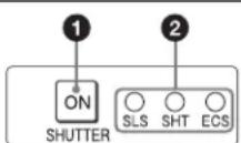
①ON button
Turns the camera SLS function, shutter function, or ECS function ON and OFF. Pressing the button causes it to light and turns the function ON. Pressing the button again causes it to go dark and turns the function OFF.
②SLS/SHUTTER/ECS indicators
The indicator for the function selected via the menu lights.
SLS: Slow Shutter mode
SHT: Shutter mode
ECS: ECS (Extended Clear Scan) mode
12 White balance/black balance control block
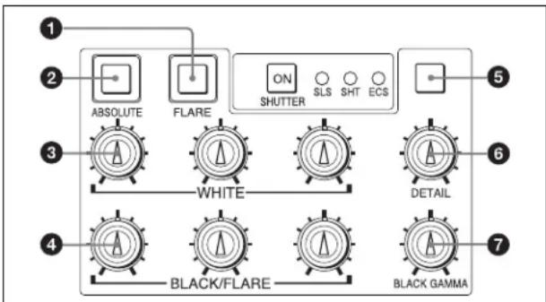
①FLARE (flare balance adjustment mode) button
Toggle the black balance adjustment mode and flare balance adjustment mode for the BLACK/FLARE knobs. Press and light the button to select the flare balance adjustment mode. Press the button again so that it goes dark when adjusting the black balance.
②ABSOLUTE (absolute value mode) button
Press and light up this button to set the mode of manual adjustment with the WHITE, BLACK, FLARE, BLACK GAMMA, and DETAIL knobs from Relative mode to Absolute mode.
In the following cases, Relative mode is automatically selected (the lit button goes dark).
- When an automatic setup (level, white, black) is completed.
- When a scene file is retrieved.
- When the adjustment mode is switched between the flare balance and black balance by pressing the FLARE button.
- When the controlled CCU/HDCU is changed due to the RCP Assign settings of the master setup unit (MSU).
When the PANEL ACTIVE button is out, or one of the PARA, MASTER, or SLAVE buttons is lit. Relative mode is automatically selected and this ABSOLUTE button is not operative.
③WHITE (white balance manual adjustment) knobs
Used to manually adjust the white balance. From the left, the knobs are for R, G, and B signal adjustment.
④BLACK/FLARE (black balance/flare balance manual adjustment) knobs
Used to manually adjust the black balance (when the FLARE button is out) or the flare balance (when the FLARE button is lit).
From the left, the knobs are for R, G, and B signal adjustment.
⑤Spare button
For future use.
⑥DETAIL adjustment knob
Turn to adjust the detail level.
⑦BLACK GAMMA adjustment knob
Turn to adjust the black gamma.
13 Camera number/tally indication window
The number of the camera being controlled from this panel is displayed in orange.
When a red tally signal is sent to the camera, the number is displayed in black and the background of the number lights in red.
When a green tally signal is sent to the camera, the number is displayed in black and the background of the number lights in green.
When both the red and green tally signals are simultaneously sent, the left half of the background lights in red and the right half lights in green.
14 NETWORK indicator
Indicates the status during connection to an Ethernet system.
Lit: Normal connection to the control device (CCU/HDCU) is established.
Flashing: There is no connection to the control device (CCU/HDCU).
Out: No camera network connection is established, or settings for connection to an Ethernet system are not configured.
15 ALARM indicator
Lights in red when trouble occurs in the camera system and the self-diagnostic function activates at the video camera head or the CCU/HDCU.
16OPT (optical) indicators
When this panel is used in a camera system with optical fiber connection, indicates the reception status of the optical signal (the reception level).
The CAM indicator shows the reception status for the CCU/HDCU-to-camera link. The CCU indicator shows the reception status for the camera-to-CCU/HDCU link.
Green: Good reception
Orange: Weakened reception
Red: Severely weakened reception
Out: Connection problem, or no optical fiber connection
17 PANEL ACTIVE button
Press and light up this button to enable control (panel active condition) of the camera system connected to this panel. The IRIS/MB ACTIVE button will also be lit at the same time.
If you press this button so that it goes dark, the panel will be locked, preventing accidental misoperation.
18 CALL button
Press this button so that signal is sent to the camera and the CALL button on the camera lights. If the tally lamps on the camera and the red tally lamp on the CCU/HDCU were lit, they will go dark. Conversely, if they were out, they will light.
When the CALL button on the camera is pressed, the CALL button on this panel lights and a buzzer sounds.
19 Expanded camera/CCU function ON/OFF buttons (RCP-921 only)

①KNEE OFF button
Press and light up this button to turn the knee function OFF.
②DETAIL OFF button
Press and light up this button to turn the detail function OFF.
③Spare button
For future use.
Iris/master black control block (RCP-920)

①EXT (lens extender) indicator
EXT: Lights when lens extender is used.
D EXT: Lights when digital extender function is ON in a camera equipped with that function.
②Spare button
For future use.
③ AUTO button
Press and light up this button to automatically adjust the iris according to the amount of input light.
While the button is lit, the reference value for auto adjustment can be fine-adjusted in the range of ±1F .
If you press the button when lit, it goes dark and Manual iris adjustment is enabled.
④ IRIS/MB ACTIVE (iris/master black active) button
Press and light up this button to enable iris, CLOSE button, and master black controls on the panel.
When the PANEL ACTIVE button is pressed, this button also lights up.
⑤IRIS RELATIVE button
When the IRIS/MB ACTIVE button is lit, the iris manual adjustment mode can be selected with this button. Press and light up the button for the Relative mode or press so that it goes dark for Absolute mode. When the IRIS/MB ACTIVE button is out, Relative mode is automatically selected and this button is not operative.
6 IRIS display
Displays the F number of the current iris setting. When the lens is closed, "CL" is displayed.
⑦MASTER BLACK RELATIVE button
When the IRIS/MB ACTIVE button is lit, the master black adjustment mode can be selected with this button. Press and light up the button for the Relative mode or press so that it goes dark for Absolute mode. When the IRIS/MB ACTIVE button is out, Relative mode is automatically selected and this button is not operative.
⑧MASTER BLACK display
Displays the current master black setting in the range from -99 to +99.
⑨SENS (sensitivity) control knob
Used for manual iris adjustment in Absolute mode. This control is not operative when Relative mode is selected.
See the table "Iris adjustment functions" (page 54).
⑩COARSE control knob
Used for manual iris adjustment.
See the table "Iris adjustment functions" (page 54).
⑪Master black control ring
Turn to manually adjust the master black level.
The setting is displayed on the MASTER BLACK display.
⑫IRIS control lever/preview switch
When the AUTO button is out, you can adjust the iris manually by moving the lever.
When the AUTO button is lit, the reference value for automatic iris adjustment can be set in a range of ±1F with this lever.
Press the switch axially to output preview key signals from the EXT I/O connector.
See the table "Iris adjustment functions" (page 54).
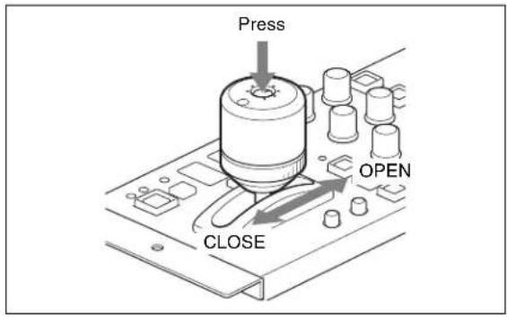
Iris adjustment functions
| Relative mode(IRIS RELATIVE button lit) | Absolute mode(IRIS RELATIVE button out) | |
| IRIS lever (RCP-920)IRIS control knob(RCP-921) | Adjusts the iris with relative values within 1/4 of the total range from OPEN to CLOSED. | Adjusts the iris within the variable range set by the SENS and COARSE controls. |
| COARSE control knob | Adjusts the total range from OPEN to CLOSED in relative values. | Sets the lower limit for CLOSED. |
| SENS control knob | Does not function. | Sets the upper limit for OPEN, referenced to the CLOSED value set by the COARSE control. |
Iris/master black control block (RCP-921)
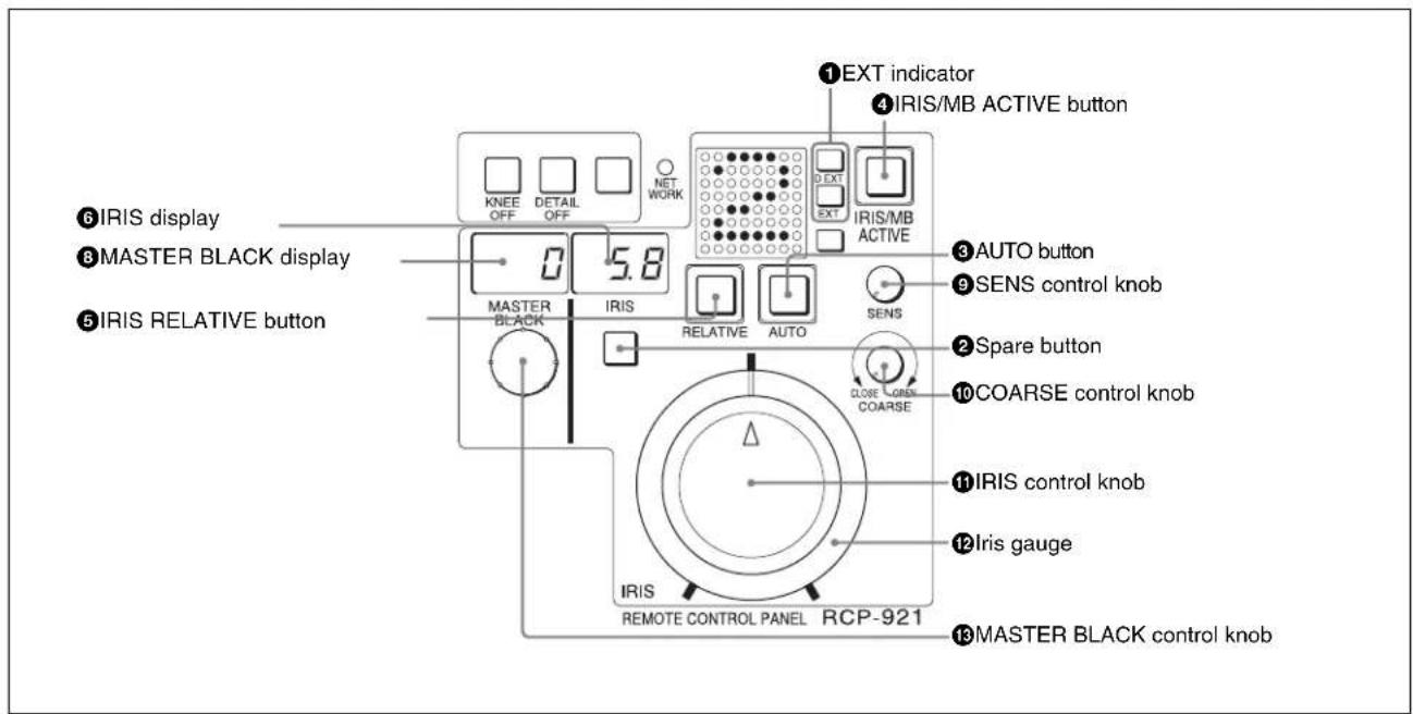
Parts 1 through 10 have the same function as shown for the RCP-920.
⑪IRIS control
When the AUTO button is out, you can adjust the iris manually by turning the control.
When the AUTO button is lit, the reference value for automatic iris adjustment can be set in a range of ±1F with this control.
See the table "Iris adjustment functions" (page 54).
⑫Iris gauge
The white line on the gauge provides a click position for the IRIS control. Turn the gauge to set the line to the most frequently used iris position, and it can be used as the reference for manual iris adjustment.
The gauge rotates infinitely in either direction. When no click position is required, set the line outside the rotation range of the IRIS control.
⑬MASTER BLACK control knob
Manually adjust the master black level.
The setting is displayed on the MASTER BLACK display.
Connector Panel

① (network) connector (8-pin RJ-45)
Used for establishing an Ethernet connection.
Connect to the network (10BASE-T/100BASE-TX) hub using a network cable (shielded type with Category 5 and higher). Through this connector, you can receive power from devices, such as hubs supporting PoE, that are compatible with IEEE802.3af standard.
CAUTION
For safety, do not connect the connector for peripheral device wiring that might have excessive voltage to this port.
Follow the instructions for this port.
ATTENTION
②CCU/CNU REMOTE (camera control unit/camera command network unit remote) connector (8-pin multiconnector, female)
Connects to the RCP/CNU connector of the camera control unit or the RCP connector of the camera command network unit.
③ AUX REMOTE (auxiliary remote) connector (8-pin multiconnector, female)
Connects to the RCP-700/701.
Note
The AUX REMOTE connector supplies power to the remote control panel (RCP). Do not connect anything other than the RCP to this connector.
④EXT I/O connector (10-pin, male)
Supplies preview signals.
Menu Configuration and Basic Operation
The RCP-920/921 provides menu operations for various functions such as adjustments of system equipment.
Basic operation
In the factory default condition, the first page of the paint menu appears on the LCD panel when power is supplied. During subsequent use, the last used menu page will appear.
For information on how to switch from and to other menu pages, see “Menu transition diagram” (page 59).
Paint menu
1 Display the menu.
The paint menu appears when power is supplied. To call up other paint menu pages, press ▲ or ▼ on the MENU UP/DOWN button in the paint control block.
2 Set or adjust the item.
Turn the paint control for the respective setting to adjust the value (or select a setting).
Note
In the following cases, some items cannot be operated from the paint menu.
| Button status Unavailable items | |
| ABSOLUTE button: Lit WHITE | COLOR TEMPDETAIL LEVEL |
| ABSOLUTE button: LitFLARE button: Out | BLACK |
| ABSOLUTE button: LitFLARE button: Lit | FLARE |
| ABSOLUTE button: LitSD button: Out^1) | DETAIL LEVEL |
| ABSOLUTE button: LitSD button: Lit^1) | SD DETAIL LEVEL |
1) Only when an SD function is assigned to either of the spare buttons. You can assign an SD function to the spare button in the SW ASSIGN menu of the configuration menu.
Configuration menu
1 Display the configuration menu.
Press the ENTER button once to go to the top page of the paint menu.
Press the ENTER button again and hold it for at least 1 second. The top page of the configuration menu appears.
2 Go to the page with the item to be set.
Turn the right paint control to move the cursor to the setting or adjustment item that you want to set, and press the ENTER button. A display for the respective setting appears. Use the ▲ and ▼ buttons as required to move between pages.
3 Select the item.
Turn the paint control to move the cursor to the item and press the ENTER button. The cursor shape becomes “?.”
4 Set or adjust the item.
Turn the right paint control to adjust the value (or select a setting), and press the ENTER button. The change becomes active, and the cursor shape returns to “>.”
Note
For pages which contain a “SET” item, any changes on the page will not become active until confirmed by the setting procedure. To do this, move the cursor to “SET” and press the ENTER button twice.
Basic configuration of menu pages
Paint menu
Top page

Setting/adjustment page
Example: Knee point adjustment page (accessed by selecting KNEE from the paint menu top page)

Configuration menu
Setting/adjustment page
Example: VR SETTING page

Turn to move the cursor. When a setting item spans more than one screen, the display scrolls. When a setting/adjustment item is selected, turn to change the setting.
Page with SET item
For pages which have a "SET" item, changes must be confirmed by the setting procedure before they become active.
Otherwise the changes will be lost when switching to another page.
Example: ETHERNET IF page

When you press ENTER once while the cursor is here, the cursor shape becomes “?.” Press ENTER once more to activate the changes. The cursor shape returns to “>.”
Press to move between pages in the menu.
Entering a series of numeric values
Example: CNS SETTING page

For this item, a series of separate values must be set. Pressing ENTER moves to the next field. When the last field has been set, pressing ENTER cancels the item selection and the cursor shape returns to “>.”
Press to move between pages in the menu.
Turn to change the numeric value of the selected field.
Menu transition diagram

flowchart
graph TD
    A["POWER ON"] --> B["Menu"]
    B --> C["Paint menu"]
    C --> D["KNEE 1/8 KNEE:ON POINT SLOPE SAT 0 0 0"]
    D --> E["ENTER"]
    E --> F["KNEE SHUTTER GAMMA DETAIL FLARE SAT"]
    F --> G["Press and hold ENTER"]
    G --> H["(LCD panel OFF) The LCD display and backlight turn OFF."]
    I["Configuration menu"] --> J["Enter"]
    J --> K["LCD SETTING MENU CUSTOMIZE > SETTING CONDITION"]
    K --> L["ENTER"]
    L --> M["> KNEE SHITTER GANMA DETAIL FLARE SAT STP GAM"]
    M --> N["<BUZZER VOLUME>> SWITCH 50 CALL 50"]
    N --> O["Clear"]
    O --> P["Use ▲/▼ to switch pages"]
    P --> Q["Use ▲/▼ to switch pages"]
    Q --> R["<HARDWARE INFO> MODEL NAME: RCP-921 SERIAL NO 100001 MAC-ADDRESS 00-00-00-00-00-00 STATUS: OK PROTECTED"]
Menu Items
For details on the respective functions, see the operation manual of the connected camera or CCU.
Paint menu
| Primary menu | Secondary menu | Operation/ adjustment item | Settings Function | Factory default | |
| TOP MENU — — Lists items on the paint menu | KNEE/GAMMA/FLARE/ | SHUTTER/DETAIL/SAT | |||
| SELECT MENU | KNEE Point — | Adjusts master knee | point — | ||
| Slope — Adjusts master knee slope — | |||||
| Sat — Adjusts knee saturation — | |||||
| GAMMA | R | — Adjusts R channel gamma — | |||
| Master — Adjusts master gamma — | |||||
| B | — Adjusts B channel gamma — | ||||
| FLARE | R | — Adjusts R channel flare — | |||
| G | — Adjusts G channel flare — | ||||
| B | — Adjusts B channel flare — | ||||
| BLACK | R | — Adjusts R channel black — | |||
| G | — Adjusts G channel black — | ||||
| B | — Adjusts B channel black — | ||||
| SHUTTER | Mode | — Selects shutter mode — | |||
| — | — | — | — | ||
| Speed^1) | — Selects shutter speed/ECS frequency/number of slow shutter frames | — | |||
| DETAIL | Level | — | Adjusts detail level | — | |
| Limit | — Adjusts detail limit — | ||||
| Crisp | — Adjusts crispening — | ||||
| SAT | Saturation | — | Adjusts saturation level | — | |
| — | — | — | — | ||
| — | — | — | — | ||
| STP GAM | Step^1) | — Selects step gamma — | |||
| — | — | — | — | ||
| — | — | — | — | ||
| WHITE | R | — Adjusts R channel white — | |||
| G | — Adjusts G channel white — | ||||
| B | — Adjusts B channel white — | ||||
| C TEMP | — — — | — | |||
| Bal | — Color temperature compensation — | ||||
| C.Temp | — Adjusts color temperature — | ||||
| PHASE | H Coarse | — Adjusts H Phase — | |||
| H Fine | — Adjusts H Phase fine — | ||||
| SC | — Adjusts SC Phase — | ||||
| SKIN DTL | Level | — | Adjusts skin detail level | — | |
| — | — | — | — | ||
| — | — | — | — | ||
| SELECT MENU (Continue) | SD DTL Level | — Adjusts SD detail level — | |||
| Limit — Adjusts SD detail limit — | |||||
| Crisp — Adjusts SD detail crispening — | |||||
| AUTO IRIS Level | — Adjusts auto iris level — | ||||
| Ratio — Adjusts auto iris APL ratio — | |||||
| Gain — Adjusts auto iris gain — | |||||
| SSM — | —— | — | |||
| — | — | — | — | ||
| Flicker Reduce | ON/OFF | Sets SuperMotion flicker reduction function | — | ||
| M.WHITE | Master White Gain | Master White Gain | Adjusts master white gain | — | |
| — | — | — | — | ||
| — | — | — | — | ||
1) Only the setting value is displayed. The item name is not displayed.
Configuration menu
| Primary menu | Secondary menu | Operation/ adjustment item | Settings | Function | Factory default |
| LCD SETTING | BRIGHT | 0 to 99 | Sets backlight brightness for LCD | 50 | |
| CONTRAST | 0 to 99 | Sets LCD contrast | 50 | ||
| MENU CUSTOMIZE | Sets items displayed on paint menu top page | KNEE/GAMMA/ FLARE/ SHUTTER/ DETAIL/SAT | |||
| SETTING | SW ASSIGN ^1) | SW01 | 5600K/AT KNEE/ SKIN DTL/DTL GATE/SAT/ B.GAM/IRIS REL/ SD/KNEE OFF/ GAM OFF/DTL OFF/W.CLP OFF/ CLOSE/SDDTL OFF/SEQ | Sets function assignments for each button | 5600K |
| SW02 | AT KNEE | ||||
| SW03 | SKIN DTL | ||||
| SW04 | DTL GATE | ||||
| SW05 | SAT | ||||
| SW06 | B.GAM | ||||
| SW07 | — | ||||
| SW08 | — | ||||
| SW09 | IRIS REL ^2) | ||||
| SW10 ^2) | KNEE OFF | ||||
| SW11 ^2) | DTL OFF | ||||
| SW12 ^2) | — | ||||
| SW13 ^2) | — | ||||
| Primary menu | Secondary menu | Operation/ adjustment item | Settings Function | Factory default | |
| SETTING (Continue) | VR REL MODE SET1) | WHITE Select from 1/1, 1/2, or 1/4 | Sets variable range for white balance in Relative mode | 1/2 | |
| BLACK (FLARE) Select from 1/1, 1/2, or 1/4 | Sets variable range for black (flare) balance in Relative mode | 1/2 | |||
| DETAIL Select from 1/1, 1/2, or 1/4 | Sets variable range for detail level in Relative mode | 1/2 | |||
| B.GAM Select from 1/1, 1/2, or 1/4 | Sets variable range for black gamma in Relative mode | 1/2 | |||
| RCP No. SET R | CP No. 1 to 24 | Specifies System Number | (RCP Number) of RCP unit3) | — | |
| PREVIEW CON | TACT ON/OFF Sets function for preview | signal output from EXT I/O connector on RCP | ON | ||
| CCU ON/OFF Sets function for preview | signal output from CCU | OFF | |||
| S-BUS | ON/OFF Sets function for preview | on for preview signal output to S-BUS system | OFF | ||
| LED BRIGHTNESS | SWITCH/LED | 0 to 99 | Sets lighted switch and LED brightness | 50 | |
| TALLY | 0 to 99 | Sets tally indication window brightness | 50 | ||
| 7SEGMENT | 0 to 99 | Sets brightness for 7-segment LED display (MASTER GAIN/ND/CC FILTER/IRIS/MASTER BLACK) | 50 | ||
| BUZZER VOLUME | SWITCH | 0 to 99 | Sets volume of the sound emitted when a switch on the RCP is pressed | 50 | |
| CALL | 0 to 99 | Sets call volume of buzzer | 50 | ||
| TIME | DATE XXXX / XX / XX Sets date — | ||||
| TIME | XX : XX | Sets time | — | ||
| TIME ZONE | COUNTRY | Sets time zone | (GMT) London | ||
| SECURITY MODE | MODE | NORMAL/ ENGINEER | Specifies security level | NORMAL | |
| SET | — | Specifies mode | — | ||
| CNS SETTING^1) | CNS MODE | LEGACY/ BRIDGE/MCS | Sets camera network system connection mode LEGACY: System connection using conventional 700 protocol cable BRIDGE: Mode for one-to-one connections using the network MCS: Mode for multi-camera systems using the network | LEGACY | |
| (Sub mode) LEGACY: None BRIDGE: CONNECT MCS: M/C | CONNECT: PASSIVE/ ACTIVE/SEMI-AT | Sets submode for bridge mode PASSIVE: Waits for connection ACTIVE: Actively connects SEMI-AT: Semi-automatic mode that switches between PASSIVE/ACTIVE based on device connected via 700 protocol | SEMI-AT | ||
| M/C: CLIENT | Sets submode for multi-camera system mode | CLIENT | |||
| MASTER IP ADDR | xxx.xxx.xxx.xxx | Sets master IP address of multi-camera system mode | 0.0.0.0 | ||
| TARGET IP ADDR | xxx.xxx.xxx.xxx | Sets IP address for connection target in bridge mode | 0.0.0.0 | ||
| SETTING (Continue) | ETHERNET IF1) | ETHERNET ON/OFF Turns Ethernet connection ON/OFF OFF | |||
| AUTO NEGO ON/OFF Turns the Auto Negotiation function ON/OFF | ON | ||||
| AUTO MDIX ON/OFF Turns the AUTO MDI/MDIX function ON/OFF | ON | ||||
| SPEED4) | 10M/100M Sets the connection speed 100M | ||||
| DUPLEX4) | HALF/FULL Sets the connection to full duplex or half duplex | FULL | |||
| MDI/MDIX4) | MDI/MDIX Sets MDI/MDIX MDI | ||||
| TCP/IP SETTING1) | IP ADDRESS | xxx.xxx.xxx.xxx | Sets the IP address | 0.0.0.0 | |
| SUBNET MASK | xxx.xxx.xxx.xxx | Sets the subnet mask | 0.0.0.0 | ||
| DEFAULT GATEWAY | xxx.xxx.xxx.xxx | Sets the default gateway | 0.0.0.0 | ||
| ALL RESET1) | ALL RESET — | Returns all configuration menu settings to factory defaults | — | ||
| Shutter Display | Angle | ON/OFF Turns the angle display function for shutter display ON/OFF | OFF | ||
| CONDITION | HARDWARE INFO | Model name | — | Shows model name | — |
| Serial No. | — | Shows serial number | — | ||
| Mac-address | — | Shows Mac address | — | ||
| SOFTWARE INFO | Main Version | — | Shows main program version | — | |
| Main Release Date | — | Shows main program release date | — | ||
| Main Comment | — | Shows main program ROM comments | — | ||
| PLD Version | — | Shows PLD program version | — | ||
| RCP DATA/TIME | Date | — | Shows date setting | — | |
| Time | — | Shows time setting | — | ||
| TimeZone | — | Shows time zone setting | — | ||
| CNS SETTING1) | CONNECT | — | Shows status of connection to camera network system | — | |
| CNS MODE — | Shows mode of connection to camera network system | — | |||
| RCP No. | — | Shows RCP unit's system number (RCP number) | — | ||
| TARGET/MASTER IP ADDR | — | Shows IP address of connection target BRIDGE: TARGET IP ADDR MCS: MASTER IP ADDR | — | ||
| ETHERNET IF1) | LINK | — | Shows Ethernet connection status | — | |
| ETHERNET | — | Shows whether Ethernet function is enabled/disabled | — | ||
| AUTO NEGO — | Shows whether Auto Negotiation function is ON/OFF | — | |||
| AUTO MDIX — | Shows whether AUTO MDI/MDIX function is ON/OFF | — | |||
| SPEED | — | Shows current connection speed | — | ||
| DUPLEX | — | Shows current full/half duplex status | — | ||
| MDI/MDIX | — | Shows current MDI/MDIX status | — | ||
| CONDITION (Continue) | TCP/IP SETTING ^1) | IP ADDR — Shows assigned IP address — | |||
| SUBNET MASK — Shows configured subnet mask — | |||||
| DEFAULT GATEWAY | — Shows configured default gateway — | ||||
1) Can only be displayed or configured if ENGINEER is selected as MODE on SECURITY MODE screen.
2) RCP-921 only.
3) Only enabled if CNS MODE in CNS SETTING is MCS.
4) Fixed at AUTO when AUTO NEGO is set to ON.
Items available for MENU CUSTOMIZE
| Display | Function | Left adjustment knob | Center adjustment knob | Right adjustment knob |
| K N E E | KNEE | POINT | SLOPE | SAT |
| G A M M A | GAMMA | Rch | Master | Bch |
| F L A R E | FLARE | Rch | Gch | Bch |
| B L A C K | BLACK | Rch | Gch | Bch |
| S T P G A M | STEP GAMMA | STEP | ||
| S H U T T E R | SHUTTER | SELECT | SPEED | |
| D E T A I L | DETAIL | LEVEL | LIMIT | CRISP |
| S A T | SATURATION SATURATION | |||
| W H I T E | WHITE | Rch | Gch | Bch |
| C . T E M P | COLOR TEMP | BAL | C.TEMP | |
| P H A S E | H/SC PHASE | H COARSE | H FINE | SC |
| S K I N D T L | SKIN DETAIL | LEVEL | ||
| S D D T L | SD DETAIL | LEVEL | LIMIT | CRISP |
| A . I R I S | AUTO IRIS | LEVEL | RATIO | GAIN |
| S S M | SUPERMOTION | Flicer Reduce | ||
| M . W H I T E | MASTER WHITE GAIN | M.White Gain | ||
| (Blank) | (No function assignment) | — | — | — |
Initial Settings
Configuring the RCP-920/921 Operating Environment
The RCP configuration menu allows you to configure settings on the RCP-920/921 such as the internal clock, buzzer volume, and LED and LCD brightness.
To adjust the LCD
You can adjust the brightness and contrast for the menu display panel.
1 Move the cursor to LCD SETTING in the RCP configuration menu, and press ENTER button.
The LCD settings screen appears.

2 Turn the left adjustment knob to adjust the brightness, and turn the right adjustment knob to adjust the contrast.
3 Press CLEAR button.
The first screen of the RCP configuration menu reappears.
To customize the paint menu
You can select up to eight setting items to appear in the paint menu.
1 Move the cursor to MENU CUSTOMIZE in the RCP configuration menu, and press ENTER button.
The paint menu customization screen appears.
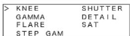
2 Turn the right adjustment knob to move the cursor to the item you want to change.

3 Press ENTER button to enable configuration.
The cursor appears as “?” and the selected item flashes.

4 Turn the right adjustment knob to change the setting item.

5 Press ENTER button to confirm the selection.
The cursor appears as “>” again.
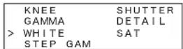
6 Repeat steps 2 to 5 for each paint menu item you want to change.
7 Press CLEAR button.
The first screen of the RCP configuration menu reappears.
To set the clock
The RCP-920/921 has an internal clock. Perform the following steps to set the clock.
1 Move the cursor to SETTING in the RCP configuration menu, and press ENTER button.
The settings and adjustment screens appear.
2 Use the ▲ and ▼ buttons to move through the settings and adjustment screens, and display the
Note
The LCD can only display up to four setting items at one time. If a page has more than four items, turn the right adjustment knob to scroll the page.
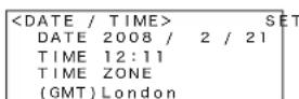
3 Turn the right adjustment knob to move the cursor to TIME ZONE.
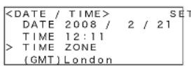
4 Set the time zone.
①Press ENTER button to enable configuration. The cursor appears as “?” and the selected time zone flashes.
②Turn the right adjustment knob to change the time zone, and press ENTER button.
The time zone is set.

5 Set the date.
①Turn the right adjustment knob to move the cursor to DATE.
②Press ENTER button to enable configuration. The cursor appears as “?” and the year setting flashes.
③Turn the right adjustment knob to change the year setting, and press ENTER button.
The month setting flashes.
④Turn the right adjustment knob to change the month setting, and press ENTER button. The day setting flashes.
⑤Turn the right adjustment knob to change the day setting, and press ENTER button.
The date is set.

6 Set the time.
①Turn the right adjustment knob to move the cursor to TIME.
②Press ENTER button to enable configuration. The cursor appears as “?” and the hour setting flashes.
③Turn the right adjustment knob to change the hour setting, and press ENTER button.
The minute setting flashes.
④Turn the right adjustment knob to change the minute setting, and press ENTER button. The time is set.
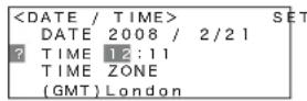
7 Save the date and time settings.
①Turn the right adjustment knob to move the cursor to SET in the upper right of the screen.
②Press ENTER button to enable configuration. The cursor appears as “?.”
③Press ENTER button again to save the settings.
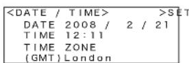
8 Press CLEAR button.
The first screen of the RCP configuration menu reappears.
To change the shutter display to an angle value
You can change settings on the RCP-920/921 to change the Step Shutter display to an angle value.
1 Move the cursor to SETTING in the RCP configuration menu, and press ENTER button.
The settings and adjustment screens appear.
2 Use the ▲ and ▼ buttons to move through the settings and adjustment screens, and display the
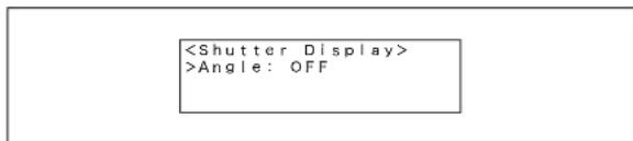
3 Change the shutter display setting.
①Press ENTER button to enable configuration. The cursor appears as “?” and the setting flashes.
②Turn the right adjustment knob to change the setting, and press ENTER button.
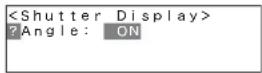
The shutter display setting is changed.
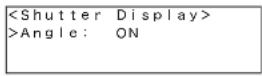
4 Press CLEAR button.
The first screen of the RCP configuration menu reappears.
The SHUTTER display on the SHUTTER page of the paint menu will be displayed as an angle (degree units).

To change the RCP number
When using the RCP-920/921 in a multi-camera network system, you must assign the unit a unique device number. When connecting the unit to a CCU directly or connecting the unit to a CNU, this configuration is not necessary.
Note
Malfunctions may occur if you assign the RCP a number that is already in use by another device in a multi-camera system connected via Ethernet. Be sure to assign a different number for each device.
1 Move the cursor to SETTING in the RCP configuration menu, and press ENTER button.
The settings and adjustment screens appear.
2 Use the ▲ and ▼ buttons to move through the settings and adjustment screens, and display the

3 Change the RCP number setting.
①Press ENTER button to enable configuration. The cursor appears as “?” and the setting flashes.
②Turn the right adjustment knob to change the setting, and press ENTER button.
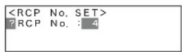
The RCP number setting is changed.
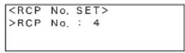
4 Press CLEAR button.
The first screen of the RCP configuration menu reappears.
To change the output destination for previews (RCP-920)
When you press the IRIS control lever/preview switch on the RCP-920, preview key signals are output. You can enable or disable the output settings for destinations individually.
The output destinations you can configure are as follows.
- EXT I/O connector on the RCP unit (Factory setting: ON)
- External output connector on the CCU (Factory setting: OFF)
• S-BUS system via the CNU (Factory setting: OFF)
1 Move the cursor to SETTING in the RCP configuration menu, and press ENTER button.
The settings and adjustment screens appear.
2 Use the ▲ and ▼ buttons to move through the settings and adjustment screens, and display the
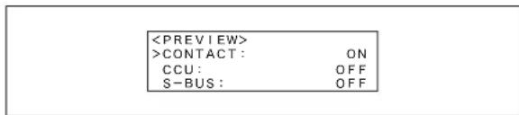
3 Turn the right adjustment knob to move the cursor to the preview output destination you want to configure.
To configure the EXT I/O connector on the RCP unit, move the cursor to CONTACT.
4 Change the preview output setting.
①Press ENTER button to enable configuration. The cursor appears as “?” and the setting flashes.
②Turn the right adjustment knob to change the setting, and press ENTER button.

The preview output setting is changed.
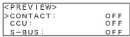
5 Press CLEAR button.
The first screen of the RCP configuration menu reappears.
To adjust LED brightness
You can adjust the brightness of buttons and the LEDs in the tally indication window on the RCP-920/921.
1 Move the cursor to SETTING in the RCP configuration menu, and press ENTER button.
The settings and adjustment screens appear.
2 Use the ▲ and ▼ buttons to move through the settings and adjustment screens, and display the

3 Turn the right adjustment knob to move the cursor to the item you want to configure.
The items you can configure are as follows.
SWITCH/LED: Adjusts the brightness for the button LEDs and the OPT and ALARM indicators.
TALLY: Adjusts the brightness for the LEDs in the camera number/tally indication window.
7SEGMENT: Adjusts the brightness for the LED number displays of the ND/CC filter, MASTER GAIN, IRIS, and MASTER BLACK indicators.
4 Set the brightness for each LED.
①Press ENTER button to enable configuration. The cursor appears as “?” and the setting flashes.
②Turn the right adjustment knob to change the setting, and press ENTER button.

The brightness is set.
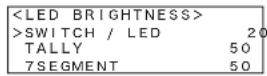
5 Press CLEAR button.
The first screen of the RCP configuration menu reappears.
To adjust the buzzer volume
When a call signal is received on the RCP-920/921 or the panel is operated, the buzzer will emit a sound. You can adjust the buzzer volume as necessary.
1 Move the cursor to SETTING in the RCP configuration menu, and press ENTER button.
The settings and adjustment screens appear.
2 Use the ▲ and ▼ buttons to move through the settings and adjustment screens, and display the

3 Turn the right adjustment knob to move the cursor to the item you want to configure.
The items you can configure are as follows. SWITCH: Adjusts the buzzer volume for when the buttons on the operation panel are pressed. CALL: Adjusts the buzzer volume for when call signals are received.
4 Set the buzzer volume for each item.
①Press ENTER button to enable configuration.
The cursor appears as “?” and the setting flashes.
②Turn the right adjustment knob to change the setting, and press ENTER button.

The buzzer volume is set.

5 Press CLEAR button.
The first screen of the RCP configuration menu reappears.
To change the security mode
The RCP-920/921 has an Engineer mode to limit access to certain settings. These settings cannot be configured unless Engineer mode is enabled.
1 Move the cursor to SETTING in the RCP configuration menu, and press ENTER button.
The settings and adjustment screens appear.
2 Use the ▲ and ▼ buttons to move through the settings and adjustment screens, and display the

3 Turn the right adjustment knob to move the cursor to MODE.
4 Change the security mode setting.
①Press ENTER button to enable configuration.
The cursor appears as “?” and the setting flashes.
②Turn the right adjustment knob to change the setting to ENGINEER, and press ENTER button.

The security mode setting is changed.
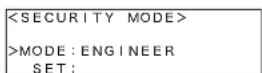
5 Save the security mode setting.
①Turn the right adjustment knob to move the cursor to SET.
②Press ENTER button to enable configuration. The cursor appears as “?” and the setting flashes.

③Press ENTER button again to save the settings.

6 Press CLEAR button.
The first screen of the RCP configuration menu reappears.
Note
The security mode returns to NORMAL when the unit is turned off.
To change switch assignments
You can change the functions of certain switches on the RCP-920/921 (the camera/CCU function ON/OFF buttons), and assign them different functions.
Note
This setting can only be configured in Engineer mode.
1 Move the cursor to SETTING in the RCP configuration menu, and press ENTER button.
The settings and adjustment screens appear.
2 Use the ▲ and ▼ buttons to move through the settings and adjustment screens, and display the
Note
The LCD can only display up to four setting items at one time. If a page has more than four items, turn the right adjustment knob to scroll the page.

3 Turn the right adjustment knob to move the cursor to the switch you want to configure.
Note
When you enter the settings configuration mode, the LEDs for all of the assignable switches dim temporarily, and only the switch selected for configuration with the cursor will remain lit. This allows you to confirm the switch for which you are currently changing the function.
4 Press ENTER button to enable configuration.
The cursor appears as “?” and the setting flashes.

5 Turn the right adjustment knob to change the setting item.

6 Press ENTER button to confirm the selection.
The cursor appears as “>” again.
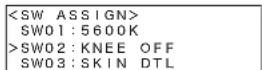
7 Repeat steps 3 to 6 for each switch you want to configure.
8 Press CLEAR button.
The first screen of the RCP configuration menu reappears.
Use the supplied function labels to relabel each switch for which the function has been changed.
To reset the settings in the RCP configuration menu
You can reset all the settings in the RCP configuration menu to their default configurations.
Note
This setting can only be configured in Engineer mode.
1 Move the cursor to SETTING in the RCP configuration menu, and press ENTER button.
The settings and adjustment screens appear.
2 Use the ▲ and ▼ buttons to move through the settings and adjustment screens, and display the
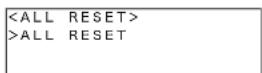
3 Reset the settings.
①Press ENTER button to enable configuration. The cursor appears as “?” and the START? display flashes.

②Press ENTER button again. OK appears, and all the settings are reset. To cancel resetting, press CLEAR button when START? is displayed.
Note
The resetting procedure is complete when OK appears, and all the settings in the RCP configuration menu will be set to their factory default configurations.
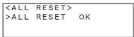
4 Press CLEAR button.
The first screen of the RCP configuration menu reappears.
To change adjustment knob sensitivity
You can adjust the sensitivity of the WHITE, BLACK/FLARE, DETAIL, and BLACK GAMMA adjustment knobs when they are used in Relative mode.
Note
This setting can only be configured in Engineer mode.
1 Move the cursor to SETTING in the RCP configuration menu, and press ENTER button.
The settings and adjustment screens appear.
2 Use the ▲ and ▼ buttons to move through the settings and adjustment screens, and display the
Note
The LCD can only display up to four setting items at one time. If a page has more than four items, turn the right adjustment knob to scroll the page.
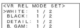
3 Turn the right adjustment knob to move the cursor to the item you want to change.
4 Change the sensitivity for each adjustment knob.
①Press ENTER button to enable configuration.
The cursor appears as “?” and the setting flashes.
②Turn the right adjustment knob to change the setting, and press ENTER button.

The sensitivity is changed.
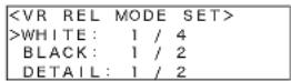
5 Press CLEAR button.
The first screen of the RCP configuration menu reappears.
To configure system connection settings
The RCP-920/921 supports system connections via the CCU/CNU REMOTE connector and connections to camera network systems via the Ethernet connector. Perform the following steps to configure system connection settings.
Notes
- To apply the configurations, you must restart the unit.
- This setting can only be configured in Engineer mode.
1 Move the cursor to SETTING in the RCP configuration menu, and press ENTER button.
The settings and adjustment screens appear.
2 Use the ▲ and ▼ buttons to move through the settings and adjustment screens, and display the
Note
The LCD can only display up to four setting items at one time. If a page has more than four items, turn the right adjustment knob to scroll the page.

3 Select a system connection mode.
The following three modes are available. Select one based on your system environment.
LEGACY: Select this mode when using the CCU/CNU REMOTE connector and a CCA-5 cable for system connection.
BRIDGE: Select this mode when using Ethernet to connect the RCP to a CCU or camera on a one-to-one basis.
MCS: Select this mode when using Ethernet to connect to a multi-camera system (MCS) comprised of multiple cameras, CCUs, and panels.
(Factory setting: LEGACY)
Notes
- For details on selecting your mode, see one of the sections that follow: “To configure Legacy mode,” “To configure Bridge mode,” or “To configure multi-camera system (MCS) mode.”
- When using an Ethernet connection, be sure to configure the Ethernet connection settings.
4 Save the system connection settings.
①Turn the right adjustment knob to move the cursor to SET in the upper right of the screen.
②Press ENTER button to enable configuration. The cursor appears as “?.”
③Press ENTER button again to save the settings.

5 Press CLEAR button.
The first screen of the RCP configuration menu reappears.
To configure Legacy mode
1 Set the camera network system mode (CNS MODE) to Legacy.
①Turn the right adjustment knob to move the cursor to CNS MODE.
②Press ENTER button to enable configuration.
The cursor appears as “?” and the setting flashes.
③Turn the right adjustment knob to select LEGACY, and press ENTER button.
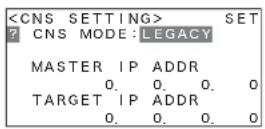
The CNS mode is set.

2 Save the system connection settings.
①Turn the right adjustment knob to move the cursor to SET in the upper right of the screen.
②Press ENTER button to enable configuration. The cursor appears as “?.”
③Press ENTER button again to save the settings.
3 Press CLEAR button.
The first screen of the RCP configuration menu reappears.
To configure Bridge mode
Bridge mode connects the RCP to the CCU on a one-to-one basis via Ethernet. The device that connects to the unit is referred to as the “target.”
1 Set the camera network system mode (CNS MODE) to Bridge.
①Turn the right adjustment knob to move the cursor to CNS MODE.
②Press ENTER button to enable configuration.
The cursor appears as “?” and the setting flashes.
③Turn the right adjustment knob to select BRIDGE, and press ENTER button.

The CNS mode is set.

2 Set the submode for Bridge mode.
In Bridge mode, you must configure the submode and target IP address to determine functioning. Under normal circumstances, set the RCP to ACTIVE or SEMI-AT.
①Turn the right adjustment knob to move the cursor to CONNECT.
②Press ENTER to enable configuration.
The cursor appears as “?” and the setting flashes.
③Turn the right adjustment knob to change the setting item.
Select one of the following based on the connection status.
ACTIVE: Connects to the target automatically.
PASSIVE: Awaits connection from the target.
SEMI-AT: Switches between Active and Passive depending on the connection environment. Active is enabled when the RCP stands alone, and Passive is enabled when the RCP is connected to a CCU or camera via CCA-5 cable.
(Factory setting: SEMI-AT)
Note
If both devices in the connection are set to Active, malfunctions may occur.
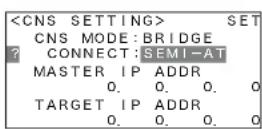
3 Set the target IP address.
①Turn the right adjustment knob to move the cursor to TARGET IP ADDRESS.
Enter the IP address of the target device for connection when Active or Semi-Auto is selected. This configuration is not necessary when Passive is selected.
②Press ENTER button to enable configuration. The cursor appears as “?” and the first section of the IP address flashes.
③Turn the right adjustment knob to change the setting, and press ENTER button. The second section of the IP address flashes. Set this section of the IP address as you did above.

④Enter the entire IP address, and press ENTER button. The target IP address is set.

4 Save the system connection settings.
①Turn the right adjustment knob to move the cursor to SET in the upper right of the screen.
②Press ENTER button to enable configuration. The cursor appears as “?.”
③Press ENTER button again to save the settings.
5 Press CLEAR button.
The first screen of the RCP configuration menu reappears.
To configure multi-camera system (MCS) mode
Use MCS mode for systems that include multiple connected CCUs, cameras, and panels such as the MSU and RCP. Configure the submode as follows to determine functioning.
1 Set the camera network system mode (CNS MODE) to MCS.
①Turn the right adjustment knob to move the cursor to CNS MODE.
②Press ENTER button to enable configuration. The cursor appears as “?” and the setting flashes.
③Turn the right adjustment knob to select MCS, and press ENTER button.
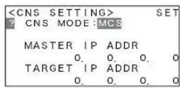
The CNS mode is set.

2 Set the master IP address.
The RCP-920/921 is always defined as a client in a multi-camera system, and the submode (Master/Client) is automatically set to CLIENT. You must set the IP address of the master device when configuring a client device in a multi-camera system.
①Turn the right adjustment knob to move the cursor to MASTER IP ADDRESS.
②Press ENTER button to enable configuration. The cursor appears as “?” and the first section of the IP address flashes.
③Turn the right adjustment knob to change the setting, and press ENTER button. The second section of the IP address flashes. Set this section of the IP address as you did above.

④Enter the entire IP address, and press ENTER button. The master IP address is set.
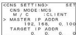
3 Save the system connection settings.
①Turn the right adjustment knob to move the cursor to SET in the upper right of the screen.
②Press ENTER button to enable configuration. The cursor appears as “?.”
③Press ENTER button again to save the settings.
4 Press CLEAR button.
The first screen of the RCP configuration menu reappears.
To configure Ethernet connection settings
The RCP-920/921 supports connections to camera network systems via the Ethernet connector. Perform the following steps to configure Ethernet connection settings.
Notes
- To apply the configurations, you must restart the unit.
- This setting can only be configured in Engineer mode.
1 Move the cursor to SETTING in the RCP configuration menu, and press ENTER button.
The settings and adjustment screens appear.
2 Use the ▲ and ▼ buttons to move through the settings and adjustment screens, and display the
Note
The LCD can only display up to four setting items at one time. If a page has more than four items, turn the right adjustment knob to scroll the page.
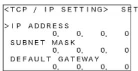
3 Configure the TCP/IP settings.
The items you can configure are as follows. IP ADDRESS: Set the IP address to assign the RCP. SUBNET MASK: Set the subnet mask of your network environment. DEFAULT GATEWAY: If necessary, set the default gateway of your network environment.
Set the IP address of this unit.
①Turn the right adjustment knob to move the cursor to IP ADDRESS.
②Press ENTER button to enable configuration. The cursor appears as “?” and the first section of the IP address flashes.
③Turn the right adjustment knob to change the setting, and press ENTER button. The second section of the IP address flashes. Set this section of the IP address as you did above.

④Enter the entire IP address, and press ENTER button. The IP address of this unit is set.

4 Set the subnet mask and default gateway.
Configure the subnet mask and (if necessary) the default gateway as you did the IP address.
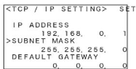
5 Save the TCP/IP settings.
①Turn the right adjustment knob to move the cursor to SET in the upper right of the screen.
②Press ENTER to enable configuration. The cursor appears as “?.”
③Press ENTER button again to save the settings.
6 Press CLEAR button.
The first screen of the RCP configuration menu reappears.
To configure Ethernet interface settings
Notes
- To apply the configurations, you must restart the unit.
- This setting can only be configured in Engineer mode.
1 Move the cursor to SETTING in the RCP configuration menu, and press ENTER button.
The settings and adjustment screens appear.
2 Use the ▲ and ▼ buttons to move through the settings and adjustment screens, and display the
Note
The LCD can only display up to four setting items at one time. If a page has more than four items, turn the right adjustment knob to scroll the page.

3 Enable or disable Ethernet interface.
When using Ethernet, enable Ethernet interface. (Factory setting: OFF)
①Turn the right adjustment knob to move the cursor to ETHERNET.
②Press ENTER button to enable configuration.
The cursor appears as “?” and the setting flashes.
③Turn the right adjustment knob to change the setting, and press ENTER button.

The Ethernet interface setting is configured.
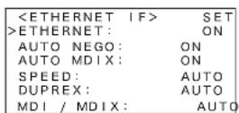
4 Configure each Ethernet interface setting.
The items you can configure are as follows.
AUTO NEGO: The Ethernet interface of this unit supports Auto Negotiation. If the devices to which you are connecting support Auto Negotiation, set this to ON and the transmission rate (Speed) and transmission method (Duplex) will be set automatically. If the devices do not support Auto Negotiation, set this to OFF. (Factory setting: ON)
AUTO MDIX: Automatically set the polarity of the Ethernet cable to be connected. If Auto Negotiation is enabled, you can set this to ON. (Factory setting: ON)
SPEED: This is the connection speed setting for the Ethernet line. If Auto Negotiation is disabled, manually configure this setting (10M or 100M) based on the devices to be connected. (Factory setting: 100M)
DUPLEX: This is the transmission method setting for the Ethernet line. If Auto Negotiation is disabled, manually configure this setting (HALF or FULL) based on the devices to be connected. (Factory setting: FULL)
MDI/MDIX: Set the polarity of the Ethernet cable to be connected. If AUTO MDIX is disabled, manually set the polarity (MDI or MDIX) based on the devices and cable to be connected. (Factory setting: MDI)
①Turn the right adjustment knob to move the cursor to the item you want to configure.
②Press ENTER button to enable configuration.
The cursor appears as “?” and the setting flashes.
③Turn the right adjustment knob to change the setting, and press ENTER button.

The Ethernet interface settings are configured.

5 Save the Ethernet interface settings.
①Turn the right adjustment knob to move the cursor to SET in the upper right of the screen.
②Press ENTER button to enable configuration. The cursor appears as “?.”
③Press ENTER button again to save the settings.
6 Press CLEAR button.
The first screen of the RCP configuration menu reappears.
Adjusting the LCD Display
The RCP-920/921 is provided with LCD-display adjustment mode, which permits you to adjust the brightness and contrast of the LCD display of the paint control block.
To enter LCD-display adjustment mode
While holding down the PARA and MASTER buttons, press the ENTER button on the paint control block. The LCD display shows the following:

To adjust the LCD display
Turn the paint controls (rotary encoders). You can adjust the brightness with the left control and the contrast with the right control.
To release LCD-display adjustment mode
Press the PARA and MASTER buttons simultaneously. The menu display before entering the LCD-display adjustment mode reappears.
Note
The values set in LCD-display adjustment mode are stored in memory when the modes are canceled. Be sure to release the modes before turning OFF the power.
Specifications
General
Power requirements 10.5 to 30 V DC
Power consumption 4 W max.
Maximum cable length
200 m (656 ft) (with CCA-5 cable connection)
Operating temperature
5^ to 40^ (41°F to 104°F)
Dimensions (w/h/d, excluding projections)
RCP-920/921: 102 × 310 × 67 mm
(4 1/8 × 12 1/4 × 2 3/4 in)
Dimensions (w/h/d, including projections)
RCP-920: 102×310×125 mm
(4 1/8 × 12 1/4 × 5 in)
RCP-921: 102 × 310 × 84 mm
(4 1/8 × 12 1/4 × 3 3/8 in)
Mass 1.8 kg (3 lb 15 oz)
Inputs/outputs
REMOTE
8-pin RJ-45 connector
CCU/CNU 8-pin multiconnector, female (1)
AUX 8-pin multiconnector, female (1)
EXT I/O 10-pin, male (1)
Supplied accessories
Operation Manual (1)
Optional accessories
External I/O connector
HIROSE HR10A-10PA-10S (74)
1-566-437-12
CCA-5-3 remote cable (3 m)
CCA-5-10 remote cable (10 m)
CCA-5-30 remote cable (30 m)
Design and specifications are subject to change without notice.
Note
Always verify that the unit is operating properly before use. SONY WILL NOT BE LIABLE FOR DAMAGES OF ANY KIND INCLUDING, BUT NOT LIMITED TO, COMPENSATION OR REIMBURSEMENT ON ACCOUNT OF THE LOSS OF PRESENT OR PROSPECTIVE PROFITS DUE TO FAILURE OF THIS UNIT, EITHER DURING THE WARRANTY PERIOD OR AFTER EXPIRATION OF THE WARRANTY, OR FOR ANY OTHER REASON WHATSOEVER.
The material contained in this manual consists of information that is the property of Sony Corporation and is intended solely for use by the purchasers of the equipment described in this manual. Sony Corporation expressly prohibits the duplication of any portion of this manual or the use thereof for any purpose other than the operation or maintenance of the equipment described in this manual without the express written permission of Sony Corporation.
商標について
Ethernet is a registered trademark of Xerox Corporation.
For Customer in China
- 各部の名称と働き
- ①液晶画面
- ②CLEAR(クリア)ボタン
- For the customers in the U.S.A.
- For the customers in Europe
- For the State of California, USA only
- Table of Contents
- Precautions
- Note on faulty pixels on the LCD panel
- Overview
- Features
- Optimized control arrangement for basic camera operation
- Auto setup control
- Scene file control
- Camera SLS/ECS/shutter function control
- Dedicated cable or Ethernet connection
- Support for parallel operation with other control panels
- Four units fit in 19-inch rack
- Examples of System Configurations
- Command cable system (for HDC series)
- About the switching hub power supply
- Precautions for Ethernet System Connections
- Note
- To connect a ground wire to the bottom of the unit
- Location and Function of Parts
- STANDARD button
- Control select block
- ①PARA (parallel mode) button
- ②MASTER and SLAVE buttons
- Power and output signal select block
- ①CAM PW (camera power) button
- ②Test signal output select buttons
- CLOSE (iris close) button
- AUTO SETUP block
- ① Auto adjustment item select buttons
- ②START/BREAK button
- ③WHITE (white balance) button
- ④BLACK (black balance) button
- Camera/CCU function ON/OFF buttons
- ①LCD panel
- ② CLEAR button
- ③ ENTER button
- ④Paint controls (rotary encoders)
- ⑤MENU UP/DOWN button
- ① SCENE FILES buttons
- ②STORE (scene file store) button
- 9Filter control block
- ①ND filter select buttons
- ②ND filter display
- ③ CC (color temperature conversion) filter display
- ④ CC (color temperature conversion) filter select buttons
- Master gain control block
- MASTER GAIN buttons and display
- SHUTTER control block
- ①ON button
- ②SLS/SHUTTER/ECS indicators
- White balance/black balance control block
- ①FLARE (flare balance adjustment mode) button
- ②ABSOLUTE (absolute value mode) button
- ③WHITE (white balance manual adjustment) knobs
- ④BLACK/FLARE (black balance/flare balance manual adjustment) knobs
- ⑤Spare button
- ⑥DETAIL adjustment knob
- ⑦BLACK GAMMA adjustment knob
- Camera number/tally indication window
- NETWORK indicator
- ALARM indicator
- 16OPT (optical) indicators
- PANEL ACTIVE button
- CALL button
- Expanded camera/CCU function ON/OFF buttons (RCP-921 only)
- ①KNEE OFF button
- ②DETAIL OFF button
- ③Spare button
- Iris/master black control block (RCP-920)
- ①EXT (lens extender) indicator
- ②Spare button
- ③ AUTO button
- ④ IRIS/MB ACTIVE (iris/master black active) button
- ⑤IRIS RELATIVE button
- IRIS display
- ⑦MASTER BLACK RELATIVE button
- ⑧MASTER BLACK display
- ⑨SENS (sensitivity) control knob
- ⑩COARSE control knob
- ⑪Master black control ring
- ⑫IRIS control lever/preview switch
- ⑪IRIS control
- ⑫Iris gauge
- ⑬MASTER BLACK control knob
- ① (network) connector (8-pin RJ-45)
- CAUTION
- ATTENTION
- ②CCU/CNU REMOTE (camera control unit/camera command network unit remote) connector (8-pin multiconnector, female)
- ③ AUX REMOTE (auxiliary remote) connector (8-pin multiconnector, female)
- ④EXT I/O connector (10-pin, male)
- Menu Configuration and Basic Operation
- Basic operation
- Paint menu
- Display the menu.
- Set or adjust the item.
- Configuration menu
- Display the configuration menu.
- Go to the page with the item to be set.
- Select the item.
- Set or adjust the item.
- Basic configuration of menu pages
- Setting/adjustment page
- Page with SET item
- Entering a series of numeric values
- Menu Items
- Initial Settings
- Configuring the RCP-920/921 Operating Environment
- To adjust the LCD
- To customize the paint menu
- To set the clock
- To change the shutter display to an angle value
- To change the RCP number
- To change the output destination for previews (RCP-920)
- To adjust LED brightness
- To adjust the buzzer volume
- Press CLEAR button.
- To change the security mode
- To change switch assignments
- To reset the settings in the RCP configuration menu
- To change adjustment knob sensitivity
- To configure system connection settings
- Notes
- To configure Legacy mode
- To configure Bridge mode
- To configure multi-camera system (MCS) mode
- Press CLEAR button.
- To configure Ethernet connection settings
- To configure Ethernet interface settings
- Adjusting the LCD Display
- To enter LCD-display adjustment mode
- To adjust the LCD display
- To release LCD-display adjustment mode
- Specifications
- General
- Inputs/outputs
- Supplied accessories
- Optional accessories
Brand : SONY
Model : RCP-920
Category : Remote control