XT-905A - Audio/video converter Planet - Free user manual and instructions
Find the device manual for free XT-905A Planet in PDF.


| Product Type | Audio/video converter |
| Brand | Planet |
| Model | XT-905A |
| Dimensions (approx.) | 100 x 60 x 25 mm |
| Weight (approx.) | 100 g |
| Power Supply | 5V DC via USB or included adapter |
| Power Consumption | 2.5 W (max) |
| Input Connectors | HDMI, RCA (composite) |
| Output Connectors | HDMI, RCA (composite), 3.5mm audio |
| Supported Video Formats | PAL, NTSC, 480p, 576p, 720p, 1080p |
| Supported Audio Formats | PCM, stereo analog |
| Functions | Conversion between HDMI and composite video/audio, upscaling, downscaling |
| Material | Plastic casing, metal connectors |
| Cleaning and Maintenance | Wipe with a dry, soft cloth. Do not use liquids or solvents. |
| Safety Precautions | Keep away from moisture and heat sources. Do not disassemble. |
| Spare Parts and Repairability | Spare parts may be available through authorized service centers. Repairs should be done by qualified professionals. |
| Warranty | Check with retailer or manufacturer for warranty details. |
| Compatible Devices | TVs, projectors, DVD players, gaming consoles, and other AV equipment with matching ports. |
| Accessories Included | Power adapter (if not USB), RCA cable, user manual |
Frequently Asked Questions - XT-905A Planet
User questions about XT-905A Planet
0 question about this device. Answer the ones you know or ask your own.
Ask a new question about this device
Download the instructions for your Audio/video converter in PDF format for free! Find your manual XT-905A - Planet and take your electronic device back in hand. On this page are published all the documents necessary for the use of your device. XT-905A by Planet.
USER MANUAL XT-905A Planet
User's Manual
10Gbps Managed Media Converter
XT-900 Series
XT-905A
XT-915A
XT-925A
natural_image
Man in white shirt using laptop in server rack (no visible text or symbols)Trademarks
Copyright © PLANET Technology Corp. 2023.
Contents are subject to revision without prior notice.
PLANET is a registered trademark of PLANET Technology Corp. All other trademarks belong to their respective owners.
Disclaimer
PLANET Technology does not warrant that the hardware will work properly in all environments and applications, and makes no warranty and representation, either implied or expressed, with respect to the quality, performance, merchantability, or fitness for a particular purpose. PLANET has made every effort to ensure that this User's Manual is accurate; PLANET disclaims liability for any inaccuracies or omissions that may have occurred.
Information in this User's Manual is subject to change without notice and does not represent a commitment on the part of PLANET. PLANET assumes no responsibility for any inaccuracies that may be contained in this User's Manual. PLANET makes no commitment to update or keep current the information in this User's Manual, and reserves the right to make improvements to this User's Manual and/or to the products described in this User's Manual, at any time without notice.
If you find information in this manual that is incorrect, misleading, or incomplete, we would appreciate your comments and suggestions.
FCC Warning
This equipment has been tested and found to comply with the limits for a Class A digital device, pursuant to Part 15 of the FCC Rules. These limits are designed to provide reasonable protection against harmful interference when the equipment is operated in a commercial environment. This equipment generates, uses, and can radiate radio frequency energy and, if not installed and used in accordance with the Instruction manual, may cause harmful interference to radio communications. Operation of this equipment in a residential area is likely to cause harmful interference in which case the user will be required to correct the interference at his own expense.
CE Mark Warning
This equipment is compliant with Class A of CISPR 32. In a residential environment this equipment may cause radio interference.
Energy Saving Note of the Device
This power required device does not support Standby mode operation. For energy saving, please remove the power cable to disconnect the device from the power circuit. In view of saving the energy and reducing the unnecessary power consumption, it is strongly suggested to remove the power connection for the device if this device is not intended to be active.
WEEE Warning
To avoid the potential effects on the environment and human health as a result of the presence of hazardous substances in electrical and electronic equipment, end users of electrical and electronic equipment should understand the meaning of the crossed-out wheeled bin symbol. Do not dispose of WEEE as unsorted municipal waste and have to collect such WEEE separately.
Revision
User's Manual of PLANET XT-900 Series
Models: XT-905A, XT-915A, XT-925A
Revision: 1.0 (July. 2023)
Part No: EM-XT-900 series_v1.0
Table of Contents
1. INTRODUCTION....7
1.1 Packet Contents....7
1.2 Product Description....8
1.3 How to Use This Manual .... 13
1.4 Product Features....14
1.5 Product Specifications....16
2. INSTALLATION....19
2.1 Hardware Description....19
2.1.1 Physical Dimensions....19
2.1.2 Front Panel 20
2.1.3 LED Indications....21
2.2 Installing the Industrial Media Converter....22
2.2.1 Installation Steps....22
2.2.2 Wall Mount Plate Mounting....22
2.3 Cabling....23
2.3.1 Installing the SFP Transceiver....23
2.3.2 Removing the SFP/SFP+ Transceiver....27
3. MEDIA CONVERTER MANAGEMENT....28
3.1 Requirements....28
3.2 Management Access Overview 29
3.3 CLI Mode Management....29
3.3.1 Remote SSH Login....30
3.3.2 Configuring IP Address....31
3.3.3 Storing the Current Switch Configuration....32
3.4 Web Management....33
3.5 SNMP-based Network Management....34
3.6 PLANET Smart Discovery Utility .... 34
4. WEB CONFIGURATION....36
4.1 Main Web Page....38
4.1.1 Save Button....39
4.1.2 Configuration Manager 40
4.1.2.1 Saving Configuration....41
4.2 System 42
4.2.1 Management....43
4.2.1.1 System Information 43
4.2.1.2 IP Configurations....44
4.2.1.3 IPv6 Configuration....46
4.2.1.4 User Configuration 48
4.2.2 Time Settings....49
4.2.2.1 System Time 49
4.2.2.2 SNTP Server Settings 52
4.2.3 Log Management....53
4.2.3.1 Logging Service ....53
4.2.3.2 Local Logging....54
4.2.3.3 Remote Syslog....55
4.2.3.4 Logging Message....57
4.2.4 SNMP Management ....59
4.2.4.1 SNMP Overview....59
4.2.4.2 SNMP Setting....60
4.2.4.3 SNMP Community....61
4.2.4.4 SNMP View 62
4.2.4.5 SNMP Access Group....63
4.2.4.6 SNMP User 65
4.2.4.7 SNMPv1, 2 Notification Recipients....67
4.2.4.8 SNMPv3 Notification Recipients....69
4.2.4.9 SNMP Engine ID....70
4.2.4.10 SNMP Remote Engine ID....71
4.2.5 RMON....72
4.2.5.1 RMON Statistics....72
4.2.5.2 RMON Event....74
4.2.5.3 RMON Event Log....75
4.2.5.4 RMON Alarm....76
4.2.5.5 RMON History....79
4.2.5.6 RMON History Log 80
4.2.6 Remote Management 81
4.2.6.1 Planet NMS Controller 81
4.2.6.2 Planet CloudViewer App....82
4.3 Switching....83
4.3.1 Port Management....84
4.3.1.1 Port Configuration 84
4.3.1.2 Port Counters 86
4.3.1.3 Link Fault Passthrough 91
4.3.1.4 Jumbo Frame....93
4.3.1.5 Protected Ports 94
4.3.1.6 EEE....96
4.3.1.7 SFP Module Information....97
4.3.1.7.1 SFP Module Status....97
4.3.1.7.2 SFP Module Detail Status....99
4.3.2 VLAN 100
4.3.2.1 VLAN Overview....100
4.3.2.2 IEEE 802.1Q VLAN....101
4.3.2.3 Management VLAN....105
4.3.2.4 Create VLAN 106
4.3.2.5 Interface Settings....107
4.3.2.6 Port to VLAN 111
4.3.2.7 Port VLAN Membership 112
4.3.3 LLDP....113
4.3.3.1 Link Layer Discovery Protocol....113
4.3.3.2 LLDP Global Setting....113
4.3.3.3 LLDP Port Setting 116
4.3.3.4 LLDP Local Device....119
4.3.3.5 LLDP Remove Device....120
4.3.3.6 LLDP Statistics....121
4.3.4 MAC Address Table 123
4.3.4.1 Static MAC Setting....123
4.3.4.2 MAC Filtering 124
4.3.4.3 Dynamic Address Setting....125
4.3.4.4 Dynamic Learned....126
4.4 Quality of Service 127
4.4.1 Understanding QoS....127
4.4.2 General....128
4.4.2.1 QoS Properties....128
4.4.2.2 QoS Port Settings 129
4.4.2.3 Queue Settings 130
4.4.2.4 CoS Mapping 131
4.4.2.5 DSCP Mapping ....132
5.1 Address Table....165
5.2 Learning 165
5.3 Forwarding & Filtering 165
5.4 Store-and-Forward 165
5.5 Auto-Negotiation....166
- TROUBLESHOOTING....167
1. INTRODUCTION
The descriptions of PLANET 10Gbps Managed Media Converters are as follows:
| XT-905A | 1-Port 10G/5G/2.5G/1G/100BASE-T + 1-Port 10G/1GBASE-X SFP+ 10G Managed Media Converter |
| XT-915A | 2-Port 10G/1GBASE-X SFP+ 10G Managed Media Converter |
| XT-925A | 1-Port 10G/5G/2.5G/1G/100BASE-T + 2-Port 10G/1GBASE-X SFP+ 10G Managed Media Converter |
"10G Managed Media Converter" is used as an alternative name for the above models in this user's manual.
1.1 Packet Contents
Open the box of the 10G Managed Media Converter and carefully unpack it. The box should contain the following items:
| Contents\Model Number | XT-905A | XT-915A | XT-925A |
| The Media Converter | |||
| Quick Start Guide Sheet | |||
| DC 12V/1.5A Power Adapter | |||
| SFP Dust Cap 1 2 2 |
If any of these are missing or damaged, please contact your dealer immediately; if possible, retain the carton including the original packing material, and use them again to repack the product in case there is a need to return it to us for repair.
1.2 Product Description
Ultra-fast Connections and Secure Management
PLANET XT-925A high-performance media converter improves network connectivity and provides sophisticated management capabilities. It is the first 10G media converter in the industry with standalone secure management, making it the best option for enterprise and telecom remote management and monitoring. The XT-925A allows for remote management via an intuitive web interface, command line interface (CLI) and SNMP protocol, enabling easy monitoring and configuration of the converter from anywhere.
Our cutting-edge converter features one 10GBASE-T copper port and two 10G SFP+ ports, integrating the power of 10G connectivity with the versatility of fiber and copper ports. This powerful yet compact solution makes it the ideal choice for businesses looking to boost their network speed and functionality.
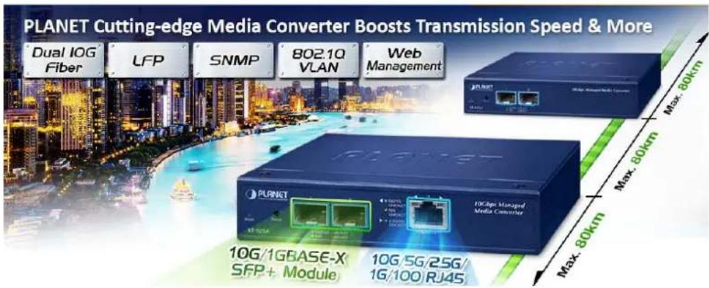
10GBASE-T and 10GBASE-X SFP Dual Media Interfaces for Diversified Bandwidth Applications
The XT-925A can reach speeds of up to 10Gbps over copper or fiber-optic cabling, greatly improving the performance of large data transmissions. Its built-in 10GBASE-T copper interfaces feature 5-speed auto-negotiation (10G/5G/2.5G/1G/100) and can transmit data at 10Gbps over the existing Cat6A/Cat7 UTP cabling, eliminating the need for expensive upgrades. With its Plug and Play design, installation is easy and hassle-free, so you can enjoy the speed you need without any extra effort.
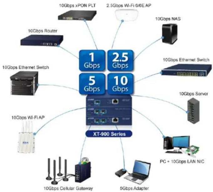
flowchart
graph TD
    A["XT-900 Series"] --> B["1 Gbps"]
    A --> C["2.5 Gbps"]
    A --> D["5 Gbps"]
    A --> E["10 Gbps"]
    B --> F["10Gbps xPON PLT"]
    B --> G["2.5Gbps Wi-Fi 6/6E AP"]
    C --> H["10Gbps NAS"]
    D --> I["10Gbps Wi-Fi AP"]
    D --> J["10Gbps Ethernet Switch"]
    E --> K["10Gbps Server"]
    E --> L["PC + 10Gbps LAN NIC"]
    E --> M["5Gbps Adapter"]
    E --> N["10Gbps Cellular Gateway"]
The fiber-optic 10GBASE-X SFP+ interfaces support 4 speeds, 10GBASE-SR/LR, 2500BASE-X, 1000BASE-SX/LX and 100BASE-FX, meaning the administrator now can flexibly choose the suitable SFP/SFP+ transceiver according to the transmission distance or the transmission speed required to extend the network efficiently.
Two Fiber Optic Ports Double the Distance of Deployment (Apply to XT-915A and XT-925A)
Conventional media converters typically support only a single pair of different media conversions, such as converting one fiber to one copper connection. They can extend a 100m copper connection to a maximum of 120km fiber optic connection. In contrast, the XT-925A has two fiber optic ports and one copper port, enabling the two fiber optic cables to connect to devices up to 240km apart so as to significantly extend the deployment distance.
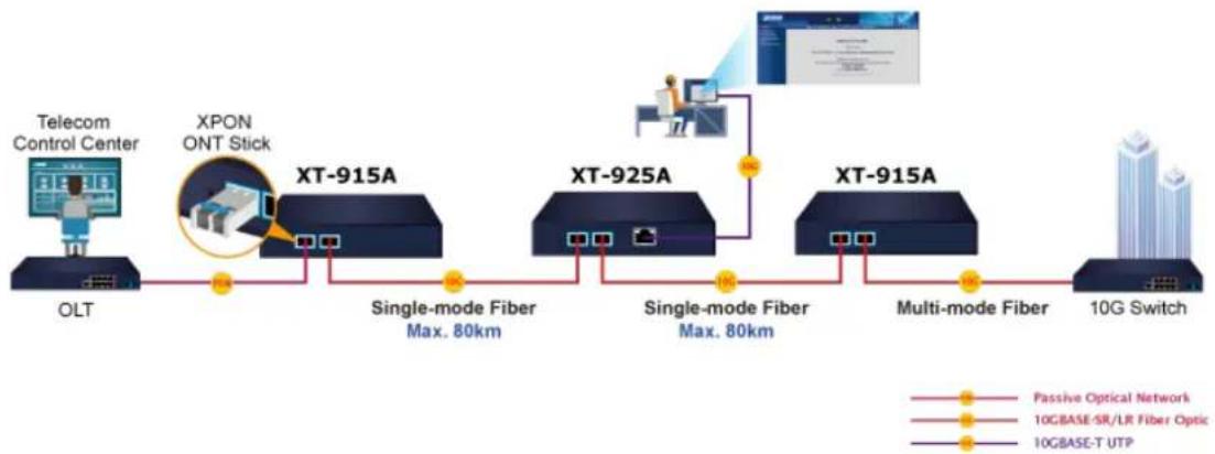
flowchart
graph LR
    A["Telecom Control Center"] --> B["OLT"]
    C["XPON ONT Stick"] --> D["XT-915A"]
    D --> E["Single-mode Fiber Max. 80km"]
    E --> F["XT-925A"]
    F --> G["Single-mode Fiber Max. 80km"]
    G --> H["XT-915A"]
    H --> I["Multi-mode Fiber"]
    I --> J["10G Switch"]
    style A fill:#f9f,stroke:#333
    style C fill:#f9f,stroke:#333
    style D fill:#ccf,stroke:#333
    style F fill:#ccf,stroke:#333
    style H fill:#ccf,stroke:#333
    style I fill:#ccf,stroke:#333
    style J fill:#ccf,stroke:#333
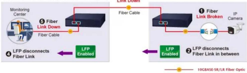
Link Fault Pass-through
Link Fault Pass-through is a networking feature. It facilitates the detection and propagation of link faults or errors from one network device to another. It helps maintain network reliability and minimizes downtime by allowing devices to dynamically respond to link faults. Link Fault Pass-through improves fault detection and enables faster troubleshooting and resolution processes.
How it works:
- When a link fault occurs, the device experiencing the fault generates a notification.
• This notification is then forwarded to other connected devices using Link Fault Pass-through. - Upon receiving the link fault information, the connected devices become aware of the fault.
• This awareness enables them to take appropriate actions, such as rerouting traffic or disabling the affected port.
Remote Link Normal (Copper to Fiber Pair)
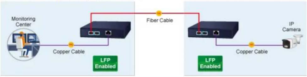
flowchart
graph LR
    A["Monitoring Center"] -->|Copper Cable| B["Server"]
    B -->|LFP Enabled| C["Fiber Cable"]
    C -->|LFP Enabled| D["Server"]
    D -->|Copper Cable| E["IP Camera"]
Remote Link Broken
Copper and Fiber are configured based on LFP group
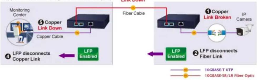
flowchart
graph TD
    A["Monitoring Center"] -->|⑤ Copper Link Down| B["Copper Cable"]
    B --> C["Fiber Cable"]
    C --> D["IP Camera"]
    D --> E["LFP Enabled"]
    E --> F["② LFP disconnects Fiber Link"]
    F --> G["① Copper Link Broken"]
    G --> H["IP Camera"]
    style A fill:#f9f,stroke:#333
    style B fill:#ccf,stroke:#333
    style C fill:#cfc,stroke:#333
    style D fill:#fcc,stroke:#333
    style E fill:#cff,stroke:#333
    style F fill:#ffc,stroke:#333
    style G fill:#fcf,stroke:#333
    style H fill:#cff,stroke:#333
Remote Link Normal (Copper to Fiber Pair)
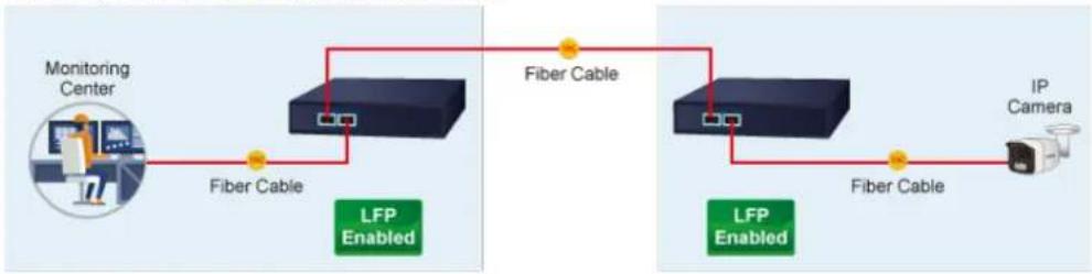
flowchart
graph LR
    A["Monitoring Center"] -->|Fiber Cable| B["Network"]
    B -->|Fiber Cable| C["IP Camera"]
    B -->|LFP Enabled| D["Network"]
    D -->|Fiber Cable| E["Network"]
    E -->|Fiber Cable| F["Network"]
Remote Link Broken
Copper and Fiber are configured based on LFP group
flowchart
graph LR
    A["Monitoring Center"] -->|⑤ Fiber Link Down\nFiber Cable| B["Router"]
    B --> C["Fiber Cable"]
    C --> D["IP Camera"]
    D --> E["1 Fiber Link Broken"]
    E --> F["LFP Enabled"]
    F --> G["2 LFP disconnects Fiber Link in between"]
    G --> H["② Fiber Link Broken"]
    H --> I["① Fiber Link Broken"]
    I --> J["Link Down"]
    J --> K["④ LFP disconnects Fiber Link"]
    K --> L["④ LFP Disconnects Fiber Link"]
    style A fill:#f9f,stroke:#333
    style B fill:#ccf,stroke:#333
    style C fill:#cfc,stroke:#333
    style D fill:#fcc,stroke:#333
    style E fill:#cff,stroke:#333
    style F fill:#ffc,stroke:#333
    style G fill:#cfc,stroke:#333
    style H fill:#fcc,stroke:#333
    style I fill:#ffc,stroke:#333
    style J fill:#cfc,stroke:#333
    style K fill:#fcc,stroke:#333
    style L fill:#ffc,stroke:#333
Network with Cybersecurity Helps Minimize Risks
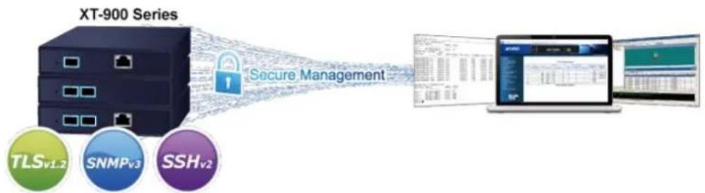
The XT-925A is equipped with enhanced cybersecurity features to fend off cyber threats and attacks. It supports SSHv2, TLSv1.2, and SNMPv3 protocols to provide strong protection against advanced threats. To safely transmit critical data to colleagues or customers via fiber optic cabling, the XT-925A's cybersecurity feature protects network management and enhances the security of mission-critical networks without incurring any additional deployment cost or effort.
flowchart
graph LR
    A["XT-900 Series"] --> B["Secure Management"]
    B --> C["Laptop Interface"]
    C --> D["Server Interface"]
    subgraph Client Nodes
        E["TLSv1.2"]
        F["SNMPv3"]
        G["SSHv2"]
    end
Redundant Ring, Fast Recovery for Critical Network Applications
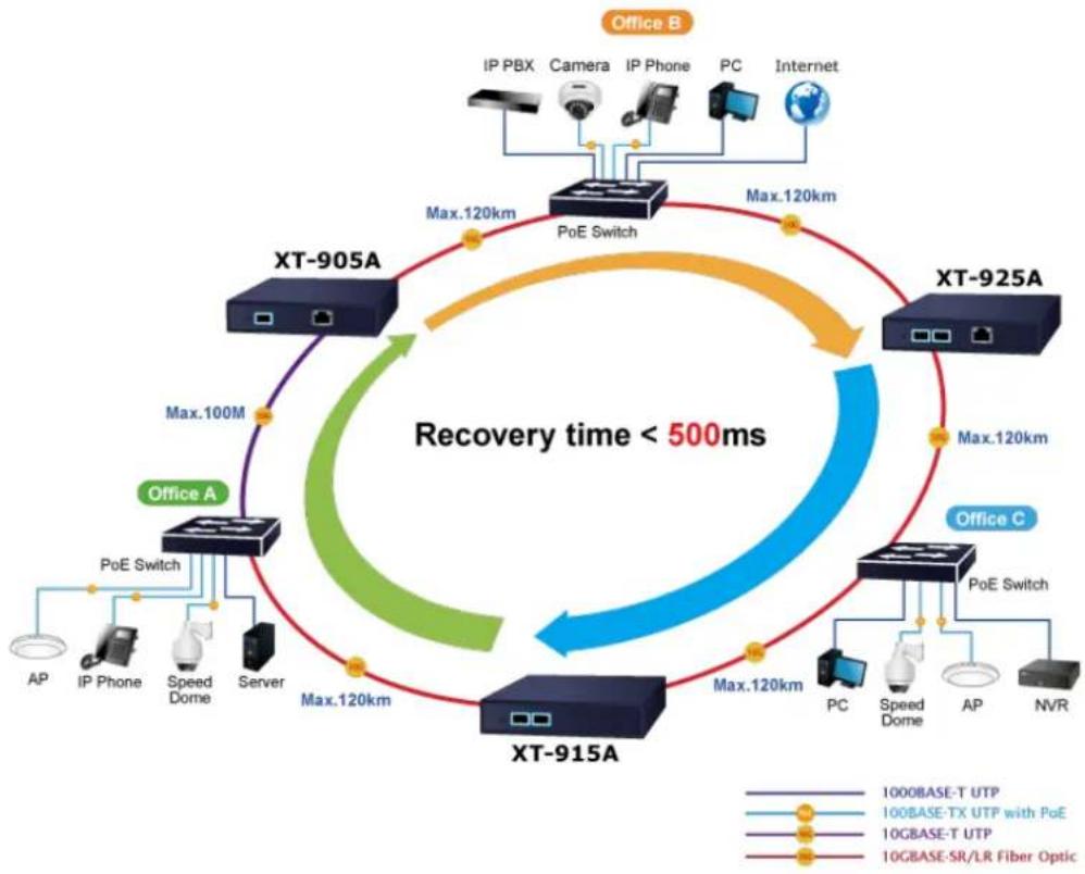
The XT-925A supports software-based redundant ring technology and features strong, rapid self-recovery capability to prevent interruption and external intrusions. It incorporates advanced ITU-T G.8032 ERPS (Ethernet Ring Protection Media convertering) technology, ensuring rapid self-recovery in ring networks. With this advanced feature, the data link recovery time can be as fast as 500ms.
flowchart
graph TD
    subgraph_Office_A["Office A"]
        A1["AP"] --> A2["IP Phone"]
        A2 --> A3["Speed Dome"]
        A3 --> A4["Server"]
        A4 --> A5["PoE Switch"]
        A5 --> A6["Max.120km"]
        A6 --> A7["XT-905A"]
        A7 --> A8["Max.100M"]
        A8 --> A9["XT-915A"]
        A9 --> A10["Max.120km"]
    end

    subgraph_Office_B["Office B"]
        B1["IP PBX"] --> B2["Camera"]
        B2 --> B3["IP Phone"]
        B3 --> B4["PC"]
        B4 --> B5["Internet"]
    end

    subgraph_Office_C["Office C"]
        C1["PC"] --> C2["Speed Dome"]
        C2 --> C3["AP"]
        C3 --> C4["NVR"]
    end

    A7 -->|Max.120km| A9
    A9 -->|Max.120km| A10
    style Office_A fill:#f9f,stroke:#333
    style Office_B fill:#bbf,stroke:#333
    style Office_C fill:#bfb,stroke:#333
    note right of A "Recovery time < 500ms"
    note right of B Max.120km
    note right of C Max.120km
    note right of D Max.120km
    note right of E Max.120km
    note right of F Max.120km
    note right of G Max.120km
    note right of H Max.120km
    note right of I Max.120km
    note right of J Max.120km
IPv6/IPv4 Dual Stack Management
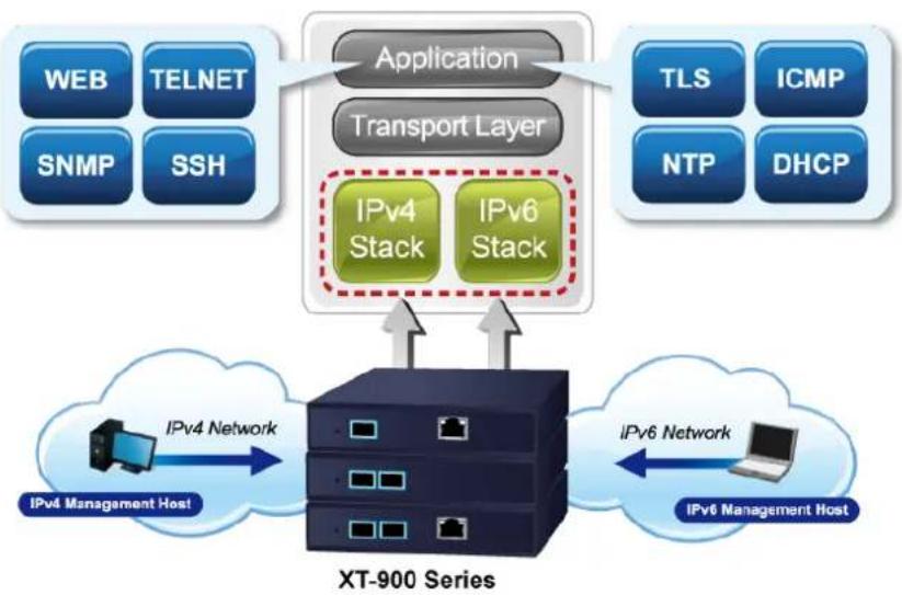
Supporting both IPv6 and IPv4 protocols, the XT-925A helps the enterprises and telecoms to step in the IPv6 era with the lowest investment as their network facilities need not be replaced or overhauled if the IPv6 FTTx edge network is set up.
flowchart
graph TD
    A["Application"] --> B["Transport Layer"]
    B --> C["IPv4 Stack"]
    B --> D["IPv6 Stack"]
    E["XP-900 Series"] --> F["IPv4 Management Host"]
    F --> G["IPv4 Network"]
    G --> H["XP-900 System"]
    I["TLS"] --> J["ICMP"]
    K["NTP"] --> L["DHCP"]
    M["SNMP"] --> N["SSH"]
    O["WEB"] --> P["TELNET"]
    Q["IPv6 Management Host"] --> R["IPV6 Management Host"]
    S["IPv6 Network"] --> T["IPV6 Management Host"]
SNMP for Comprehensive Network Monitoring and Centralized Control
SNMP (Simple Network Management Protocol) provides network monitoring and management capabilities by gathering real-time information about network devices. By proactively identifying and addressing network issues, reliability and performance are improved. SNMP also facilitates centralized control of network devices, allowing for monitoring and configuration of multiple devices from a single location, reducing manual effort and enhancing operational efficiency.
Layer 2 Features
The device has a 16K-entry MAC address table that automatically removes inactive addresses. Its backbone supports speeds of up to 60Gbps, and it can handle Jumbo Frames up to 1.2K in size. The device is equipped with Storm Control to manage Broadcast/Multicast/Unknown Unicast traffic to prevent excessive network flooding.
Efficient Traffic Control
The XT-925A media converter boasts advanced QoS features and robust traffic management capabilities, optimizing the delivery of business-class data, voice, and video solutions. Its feature set includes broadcast/multicast/unicast storm control, per-port bandwidth control, and 802.1p CoS/DSCP/IP Precedence QoS priority and remarking. These capabilities guarantee optimal performance for VoIP and video stream transmission, maximizing the utilization of limited network resources for enterprises
Intelligent SFP Diagnosis Mechanism
The XT-925A supports the SFP-DDM (digital diagnostic monitor) function, which greatly helps network administrators easily monitor real-time parameters of the SFP transceivers. These parameters include optical output power, optical input power, temperature, laser bias current, and transceiver supply voltage.
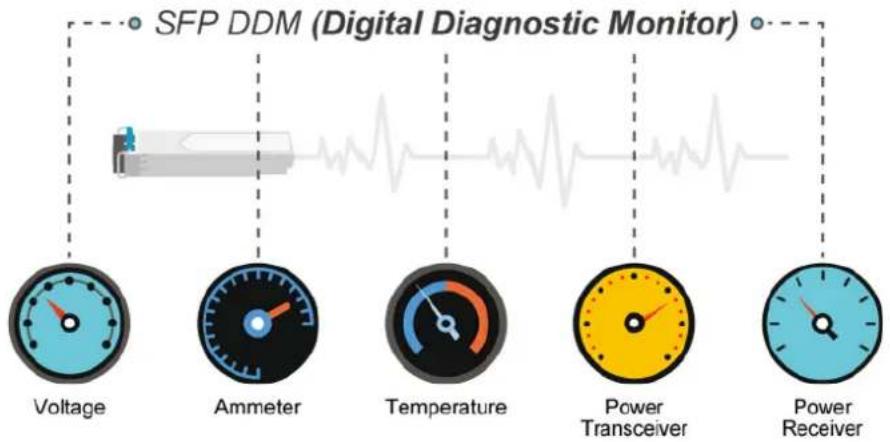
flowchart
graph TD
    A["SFP DDM (Digital Diagnostic Monitor)"] --> B["Voltage"]
    A --> C["Ammeter"]
    A --> D["Temperature"]
    A --> E["Power Transceiver"]
    A --> F["Power Receiver"]
Remote Management Solution
PLANET's Universal Network Management System (UNI-NMS) and CloudViewer app support IT staff in remotely managing all network devices and monitoring the operation statuses of the XT-925A. These systems are designed for both enterprises and industries where the deployments of the XT-925A can be remote. This allows for bugs or faulty conditions to be found without having to go to the actual location. With UNI-NMS or CloudViewer app, all kinds of businesses can now be speedily and efficiently managed from one platform.
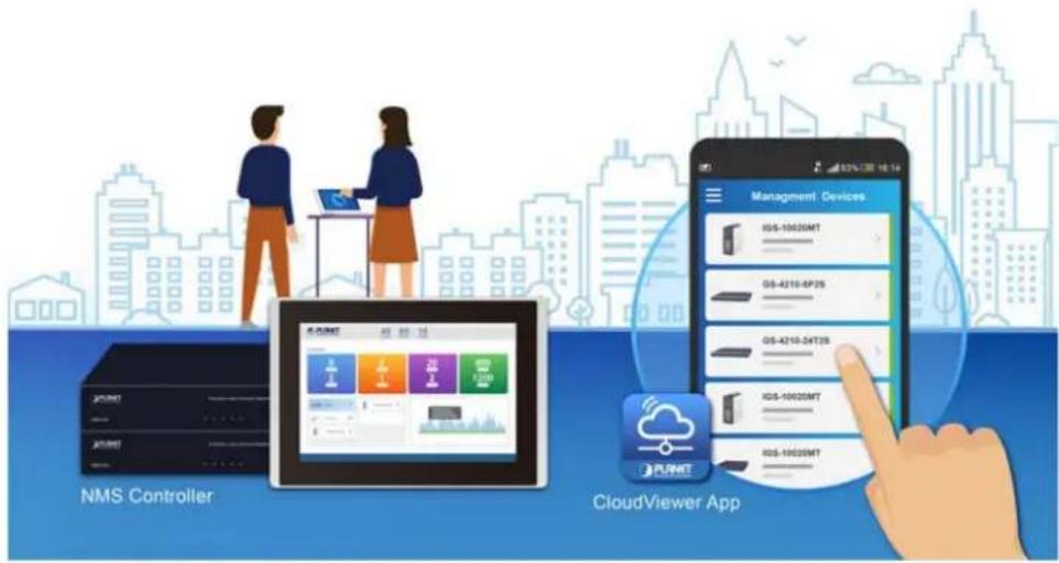
1.3 How to Use This Manual
This User's Manual is structured as follows:
Section 2, INSTALLATION
The section explains the functions of the 10G Media Converter and how to physically install the Industrial Media Converter.
Section 3, MEDIA CONVERTER MANAGEMENT
The section contains the information about the software function of the Industrial Media Converter.
Section 4, WEB CONFIGURATION
The section explains how to manage the 10G Media Converter by Web interface.
Section 5. MEDIA CONVERTER OPERATION
The chapter explains how to do the media converter operation of the Industrial Media Converter.
Section 6, TROUBLESHOOTING
The chapter explains how to do troubleshooting of the Industrial Media Converter.
Appendix A
The section contains cable information of the Industrial Media Converter.
Appendix B
The section contains glossary information of the Industrial Media Converter.
1.4 Product Features
Physical Port
■ One 10G/5G/2.5G/1G/100BASE-T RJ45 interface with auto MDI/MDI-X function
■ Two 10G/2.5G/1G/100BASE-X SFP+ interfaces
Layer 2 Features
■ Storm Control support
- Broadcast / Multicast / Unknown Unicast
■ Supports VLAN
- IEEE 802.1Q tagged VLAN
- Supports provider bridging (VLAN Q-in-Q, IEEE 802.1ad)
- Up to 256 VLAN groups, out of 4096 VLAN IDs
■ Supports ITU-T G.8032 ERPS ring with recovery time less than 500ms (software-based)
■ Link Layer Discovery Protocol (LLDP)
■ 16K MAC address table with auto-aging
■ Jumbo Frame support up to 12K in size
Quality of Service
■ Ingress Shaper and Egress Rate Limit per port bandwidth control
■ 8 priority queues on all converter ports
■ Strict priority and Weighted Round Robin (WRR) CoS policies
■ Traffic classification
- IEEE 802.1p CoS
- IP TOS / DSCP / IP Precedence
- IP TCP/UDP port number
- Typical network application
Management
■ IPv4 and IPv6 dual stack management
■ Support Link Fault Pass-through
■ Management Interfaces
- Web HTTP/HTTPS management
- Telnet Command Line Interface
- SNMP v1, v2c, v3 monitoring
- SSHv2, TLSv1.2
■ System Maintenance
- Firmware upload/download via HTTP
- Reset button for system reboot or reset to factory default
- Dual images
■ Simple Network Time Protocol (SNTP)
■ User privilege levels control
■ SNMP Management
- SNMP trap for interface link up and link down notification
– Four RMON groups (history, statistics, alarms and events)
■ Network Diagnostic
- SFP-DDM (Digital Diagnostic Monitor)
■ Syslog remote alarm
■ Local system Log
■ ICMPv6 / ICMPv4 remote ping
■ PLANET Smart Discovery Utility for deploy management
■ PLANET Remote Management
- PLANET NMS Controller and CloudViewer app for deployment management
Security
■ IP address access management to prevent unauthorized intruder
■ Static MAC setting and MAC Filtering
■ Protected ports (XT-925A only)
Case and Installation
■ External 12VDC, 1.5A power adapter
■ 0 to 50 degrees C operating temperature
■ Supports 4KVDC Contact/8KVDC Air Ethernet ESD protection
■ Wall-mount and DIN-rail installation (optional)
1.5 Product Specifications
| Model | XT-905A | XT-915A | XT-925A |
| Hardware Specifications | |||
| Copper Interface | 1x10G/5G/2.5G/1G/100BASE-T RJ45 interface with auto MDI/MDI-X function | - | 1x10G/5G/2.5G/1G/100BASE-T RJ45 interface with auto MDI/MDI-X function |
| Fiber Interface | 1x10G/2.5G/1G/100BASE-X SFP+ interface | 2x10G/2.5G/1G/100BASE-X SFP+ interface | 2x10G/2.5G/1G/100BASE-X SFP+ interface |
| Reset Button | < 5 sec.: System reboot> 5 sec.: Factory default | ||
| ESD Protection | 4KVDC Contact / 8KVDC Air | ||
| Enclosure | Compact-sized metal case | ||
| Installation | Wall-mount kit and DIN-rail kit installation (optional) | ||
| Dimensions (W x D x H) | 135 x 87.8 x 20mm | ||
| Weight | 429g (device only) | 407g (device only) | 437g (device only) |
| Power Requirement | DC 12V, 1.5A, external power adapter | ||
| Power Consumption (XT-925A) | 3.24 watts/11.06 BTU/hr (No loading) /12.5 watts/42.65 BTU/hr (Full loading) | ||
| LED Indicator | System:PWR, (Green)Per 10GBASE-T RJ45 Port:1G/100 LINK/ACT (Green)2.5G/5G LINK/ACT (Green)10G LINK/ACT (Amber)Per 10GBASE-X SFP+ Port:1G LINK/ACT (Green)2.5G LINK/ACT (Green)10G LINK/ACT (Amber) | ||
| Transmission Specifications | |||
| Processing Scheme | Store and Forward | ||
| Fabric | 40Gbps | 40Gbps | 60Gbps |
| Throughput (packet per second) | 29.76Mpps@64bytes | ||
| Address Table | 16K entries, automatic source address learning and aging | ||
| Flow Control | Back pressure for half duplexIEEE 802.3x pause frame for full duplex | ||
| Jumbo Frame 12K | |||
| Shared Buffer | 12Mbits | ||
| Layer 2 Function | |||
| Port Configuration | Port disable/enableAuto-negotiation 100Mbps, 1/2.5/5/10Gbps full and half duplex mode selectionFlow control disable/enable | ||
| Port Status | Display each port's link status, speed, Auto-negotiation status, duplex mode, flow control status | ||
| VLAN | IEEE 802.1Q tag-based VLANIEEE 802.1ad Q-in-Q tunnelingUp to 256 VLAN groups, out of 4096 VLAN IDs | ||
| Bandwidth Control | Per port bandwidth controlIngress: 16~10,000,000KbpsEgress: 16~10,000,000Kbps | ||
| QoS | Traffic classification based, strict priority and WRR8-level priority for media converteringTraffic classification:- Cos/802.1p- DSCP- IP Precedence | ||
| Ring | Supports ERPS, and complies with ITU-T G.8032Recovery time < 450ms | ||
| Security Function | |||
| Access Security | Remote management protocols support: SSH, Telnet, HTTP and HTTPSProtected ports (XT-925A only) | ||
| System Management | |||
| Basic Management Interfaces | Telnet, Web browser, SNMP v1, v2c | ||
| Secure Management Interfaces | SSHv2, TLS v1.2, SNMP v3 | ||
| System Management | Firmware upgrade by HTTP protocol through Ethernet networkConfiguration upload/download through HTTPLLDP protocolSNTPPLANET Smart Discovery UtilityPLANET NMS Controller and PLANET CloudViewer mobile app | ||
| Event Management | Remote syslogLocal system logSNMP trap | ||
| SNMP MIBs | RFC 1213 MIB-IIRFC 2863 IF-MIBRFC 1493 Bridge MIBRFC 1643 Ethernet MIBRFC 2863 Interface MIBRFC 2665 Ether-Like MIBRFC 2737 Entity MIBRFC 2819 RMON MIB (Groups 1, 2, 3 and 9)RFC 3411 SNMP-Frameworks-MIBLLDPMAU-MIB | ||
| Standards Conformance | |||
| Regulatory Compliance | FCC Part 15 Class A, CE Class A | ||
| Stability Testing | IEC60068-2-32 (free fall)IEC60068-2-27 (shock)IEC60068-2-6 (vibration) | ||
| Standards Compliance | IEEE 802.3u, 100BASE-TX/FXIEEE 802.3ab, 1000BASE-TIEEE 802.3bz, 2.5G/5GBASE-TIEEE 802.3an, 10GBASE-TIEEE 802.3z, 1000BASE-SX/LXIEEE 802.3ae 10GBASE-SR/LRIEEE 802.3x full-duplex flow controlIEEE 802.1p Class of ServiceIEEE 802.1Q VLAN taggingIEEE 802.1ad Q-in-Q VLAN stackingIEEE 802.1ab LLDPRFC 768 UDPRFC 2474 DSCP RFC 791 IPRFC 792 ICMPRFC 2068 HTTPITU-T G.8032 ERPS Ring | ||
| Environment | |||
| Operating | Temperature: 0 ~ 50 degrees CRelative Humidity: 5 ~ 95% (non-condensing) | ||
| Storage | Temperature: -10 ~ 70 degrees CRelative Humidity: 5 ~ 95% (non-condensing) | ||
2. INSTALLATION
2.1 Hardware Description
The 10G Media Converter supports multiple running speeds, including 100Mbps, 1Gbps, 2.5Gbps, and 10Gbps, and can automatically distinguish the speed of the incoming connection.
This section provides an overview of the hardware features of the 10G Media Converter. To facilitate management and control of the device, it is important to familiarize yourself with its display indicators and ports. The front panel illustrations provided in this chapter show the unit's LED indicators. Before connecting any network device to the 10G Media Converter, be sure to read this chapter carefully.
2.1.1 Physical Dimensions
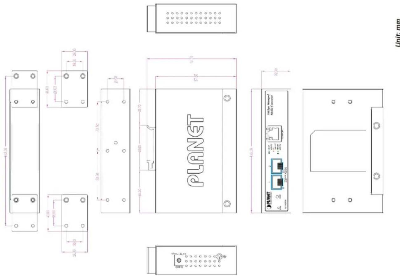
2.1.2 Front Panel

XT-905A

XT-915A

XT-925A
10G TP Interface
100/1000/2500/5000/10000BASE-T Copper, RJ45 Twisted-pair: Up to 100 meters.
SFP+ Slot
100/1000/2500/10000BASE-X mini-GBIC slot, SFP+ (Small-form Factor Pluggable) transceiver module: From 550 meters to 2km (multi-mode fiber) and to 10/20/30/40/50/70/120 kilometers (single-mode fiber). Note: the max. distance tor operating at 10G is 80km.
■ Reset Button
On the left side of the front panel, the reset button is designed for rebooting the 10G Media Converter without turning off and on the power. The following is the summary table of reset button functions:
| Reset Button Pressed and Released | Function |
| < 5 sec: System Reboot | Reboot the 10G Media Converter. |
| > 5 sec: Factory Default | Reset the 10G Media Converter to Factory Default configuration. The 10G Media Converter will then reboot and load the default settings as shown below:Default Username: adminDefault Password: adminDefault IP address: 192.168.0.100Subnet mask: 255.255.255.0Default Gateway: 192.168.0.254 |
2.1.3 LED Indications
LED Definition:
■ System and Power
| LED Color Function | |||
| PWR Green | Lit Power ON | ||
| Off Power OFF | |||
■ Per 10GBASE-T RJ45 Interface
| LED Color Function | |||
| 1G/100 Green | Lit: | To indicate the link through TP port is successfully established at 1Gbps or 100Mbps. | |
| Blink | To indicate that the media converter is actively sending or receiving data over that port. | ||
| 10G Amber | Lit: | To indicate the link through TP port is successfully established at 10Gbps. | |
| Blink | To indicate that the media converter is actively sending or receiving data over that port. | ||
| 2.5G/5G Green | Lit: | To indicate that the port is operating at 5Gbps or 2.5Gbps. | |
| Blink | To indicate that the media converter is actively sending or receiving data over that port. | ||
■ Per 10GBASE-X SFP+ Interface
| LED Color | Function | ||
| 1G/2.5GLNK/ACT | Green | Lit: | To indicate the port is running at 1G/2.5Gbps and successfully established. |
| Blink | To indicate that the Media converter is actively sending or receiving data over that port. | ||
| 10GLNK/ACT | Amber | Lit: | To indicate the port is running at 10Gbps and successfully established. |
| Blink | To indicate that the media converter is actively sending or receiving data over that port. | ||
2.2 Installing the Industrial Media Converter
This section describes how to install your 10G Media Converter and make connections to the Industrial Media Converter.
Please read the following topics and perform the procedures in the order being presented. To install your 10G Media Converter on a desktop or shelf, simply complete the following steps.
In this paragraph, we will describe how to install the 10G Media Converter and the installation points attended to it.
2.2.1 Installation Steps
- Unpack the 10G Media Converter
- If users want to wall-mount the 10G Media Converter, please refer to the Wall Mount Plate Mounting section for wall-mount plate installation.
- Hang the 10G Media Converter on the wall.
- Power on the 10G Media Converter. Please refer to the Wiring the Power Inputs section to get the information about how to wire the power. The power LED on the 10G Media Converter will light up. Please refer to the LED Indicators section for indication of LED lights.
- Prepare the twisted-pair, straight-through Category 5 cable for Ethernet connection.
- Insert one side of RJ45 cable (category 5) into the 10G Media Converter's Ethernet port (RJ45 port) while the other side to the network device's Ethernet port (RJ45 port), e.g., media converter PC or server. The UTP port (RJ45) LED on the 10G Media Converter will light up when the cable is connected with the network device. Please refer to the LED Indicators section for LED light indication.

Make sure that the connected network devices support MDI/MDI-X. If it does not support, use the crossover Category 5 cable.
- When all connections are set and all LED lights show normal, the installation is completed.
2.2.2 Wall Mount Plate Mounting
To install the 10G Media Converter on the wall, please follow the instructions below.
Step 1: Place the wall-mount plate on the rear panel of the 10G Media Converter.
Step 2: Use the screwdriver to screw the wall mount plate on the 10G Media Converter.
Step 3: Use the hook holes at the corners of the wall mount plate to hang the 10G Media Converter on the wall.
Step 4: To remove the wall mount plate, reverse the steps above.
2.3 Cabling
■ 100/1000/2500/5000/10000BASE-T
The RJ-45 copper port comes with auto-negotiation capability. They automatically support 100BASE-T, 1000BASE-T, 2.5GBASE-T, 5GBASE-T and 10GBASE-T networks. Users only need to plug a working network device into the copper port, and then turn on the 10G Media Converter. The port will automatically run at 100Mbps, 1000Mbps, 2500Mbps, 5000Mbps or 10Gbps after negotiating with the connected device.
■ 100/1000/2500/10000BASE-X
The 10G Media Converter has 1 or 2 SFP+ interfaces that support 100/1000/2500/10000Mbps dual speed mode.
■ Cabling
The 100/1000/2500/5000/10000BASE-T port uses an RJ45 socket -- similar to phone jacks -- for connection of unshielded twisted-pair cable (UTP). The IEEE 802.3ab Gigabit Ethernet standard mandates the use of 5/5e/6 UTP for 1000BASE-T (refer to the table below). Maximum distance is 100 meters (328 feet). The 100/1000/2500/10000BASE-X SFP+ slot uses an LC connector with optional SFP module. Please see table below and know more about the cable specifications.
| Port Type | Cable Type | Connector |
| 100BASE-TX | Cat5 UTP, 2-pair | RJ45 |
| 1000BASE-T | Cat5/5e/6 UTP, 2-pair | RJ45 |
| 10GbASE-T | Cat6A or Cat7 | RJ45 |
| 100BASE-FX | 50/125μm or 62.5/125μm multi-mode 9/125μm single-mode | LC (multi/single mode) |
| 1000BASE-SX/LX | 50/125μm or 62.5/125μm multi-mode 9/125μm single-mode | LC (multi/single mode) |
| 10GBASE-SR/LR | 50/125μm or 62.5/125μm multi-mode 9/125μm single-mode | LC (multi/single mode) |
Any Ethernet devices like hubs and PCs can connect to the 10G Media Converter by using straight-through wires. The 100/1000/2500/5000/10000BASE-T ports are auto-MDI/MDI-X and can be used on straight-through or crossover cable.
2.3.1 Installing the SFP Transceiver
The sections describe how to insert an SFP/SFP+ transceiver into an SFP/SFP+ slot. The SFP/SFP+ transceivers are hot-pluggable and hot-swappable. You can plug in and out the transceiver to/from any SFP/SFP+ port without having to power down the 10G Managed Media Converter as follows.
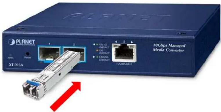
■ Approved PLANET SFP/SFP+ Transceivers
PLANET 10G Managed Media Converter supports both single mode and multi-mode SFP transceivers. The following list of approved PLANET SFP/SFP+ transceivers is correct at the time of publication:
10 Gigabit Ethernet Transceiver (10GBASE-X SFP+)
| Model | Speed (Mbps) | Connector Interface | Fiber Mode Distance | Wavelength (nm) | Operating Temp. | |
| MTB-SR | 10G | LC | Multi Mode | 300m | 850nm | 0 ~ 60 degrees C |
| MTB-LR | 10G | LC | Single Mode | 10km | 1310nm | 0 ~ 60 degrees C |
10 Gigabit Ethernet Transceiver (10GBASE-BX, Single Fiber Bi-directional SFP+)
| Model | Speed (Mbps) | Connector Interface | Fiber Mode | Distance | Wavelength (TX) | Wavelength (RX) | Operating Temp. |
| MTB-LA20 MTB-LB20 | 10G WDM (LC) | Single Mode | 20km | 1270nm | 1330nm | 0 ~ 60 degrees C | |
| 10G WDM (LC) | Single Mode | 20km | 1330nm | 1270nm | 0 ~ 60 degrees C | ||
| MTB-LA40 MTB-LB40 | 10G WDM (LC) | Single Mode | 40km | 1270nm | 1330nm | 0 ~ 60 degrees C | |
| 10G WDM (LC) | Single Mode | 40km | 1330nm | 1270nm | 0 ~ 60 degrees C | ||
| MTB-LA60 MTB-LB60 | 10G WDM (LC) | Single Mode | 60km | 1270nm | 1330nm | 0 ~ 60 degrees C | |
| 10G WDM (LC) | Single Mode | 60km | 1330nm | 1270nm | 0 ~ 60 degrees C | ||
2.5 Gigabit Ethernet Transceiver (2500BASE-X SFP)
| Model | Speed (Mbps) | Connector Interface | Fiber Mode | Distance | Wavelength (nm) | Operating Temp. |
| MGB-2GSR | 2488 | LC | Multi Mode | 300m 850nm | 0 ~ 60 degrees C | |
| MGB-2GLR2 | 2488 | LC | Single Mode | 2km 1310nm | 0 ~ 60 degrees C | |
| MGB-2GLR20 | 2488 | LC | Single Mode | 20km 1310nm | 0 ~ 60 degrees C | |
| MGB-2GLA20 | 2488 | LC | Single Mode | 20km | TX: 1310nm RX: 1550nm | 0 ~ 60 degrees C |
| MGB-2GLB20 | 2488 | LC | Single Mode | 20km | TX: 1550nm RX:1310nm | 0 ~ 60 degrees C |
Gigabit Ethernet Transceiver (1000BASE-X SFP)
| Model | Speed (Mbps) | Connector Interface | Fiber Mode | Distance | Wavelength (nm) | Operating Temp. |
| MGB-GT | 1000 | Copper | -- | 100m | -- | 0 ~ 60 degrees C |
| MGB-SX | 1000 | LC | Multi Mode | 550m | 850nm | 0 ~ 60 degrees C |
| MGB-SX2 | 1000 | LC | Multi Mode | 2km | 1310nm | 0 ~ 60 degrees C |
| MGB-LX | 1000 | LC | Single Mode | 20km | 1310nm | 0 ~ 60 degrees C |
| MGB-L40 | 1000 | LC | Single Mode | 40km | 1550nm | 0 ~ 60 degrees C |
| MGB-L80 | 1000 | LC | Single Mode | 80km | 1550nm | 0 ~ 60 degrees C |
Gigabit Ethernet Transceiver (1000BASE-BX, Single Fiber Bi-directional SFP)
| Model | Speed (Mbps) | Connector Interface | Fiber Mode | Distance | Wavelength (TX) | Wavelength (RX) | Operating Temp. |
| MGB-LA10MGB-LB10 | 1000 WDM (LC) | Single Mode | 10km | 1310nm 1550nm | 0 ~ 60 degrees C | ||
| 1550nm 1310nm | |||||||
| MGB-LA20MGB-LB20 | 1000 WDM (LC) | Single Mode | 20km | 1310nm 1550nm | 0 ~ 60 degrees C | ||
| 1550nm 1310nm | |||||||
| MGB-LA40MGB-LB40 | 1000 WDM (LC) | Single Mode | 40km | 1310nm 1550nm | 0 ~ 60 degrees C | ||
| 1550nm 1310nm | |||||||
| MGB-LA80MGB-LB80 | 1000 WDM (LC) | Single Mode | 80km | 1490nm 1550nm | 0 ~ 60 degrees C | ||
| 1550nm 1490nm | |||||||

-
It is recommended to use PLANET SFP on the 10G Managed Media Converter. If you insert an SFP/SFP+ transceiver that is not supported, the 10G Managed Media Converter will not recognize it.
-
Before we connect the 10G Managed Media Converter to the other network device, we have to make sure both sides of the SFP transceivers are with the same media type, for example: 10GBASE-SR to 10GBASE-SR, 10GBASE-LR to 10GBASE-LR.
- Check whether the fiber-optic cable type matches with the SFP transceiver requirement.
To connect to 10GBASE-SR SFP+ transceiver, please use the multi-mode fiber cable with one side being the male duplex LC connector type.
To connect to 10GBASE-LR SFP+ transceiver, please use the single-mode fiber cable with one side being the male duplex LC connector type.
- Connect the fiber cable
- Insert the duplex LC connector into the SFP/SFP+ transceiver.
- Connect the other end of the cable to a device with SFP/SFP+ transceiver installed.
- Check the LNK/ACT LED of the SFP/SFP+ slot on the front of the 10G Managed Media Converter. Ensure that the SFP/SFP+ transceiver is operating correctly.
- Check the Link mode of the SFP/SFP+ port if the link fails. To function with some fiber-NICs or Media Converters, user has to set the port Link mode to "10G FDX", "1000M FDX" or "100M FDX".
2.3.2 Removing the SFP/SFP+ Transceiver
- Make sure there is no network activity by consulting or checking with the network administrator. Or through the management interface of the media converter/converter (if available) to disable the port in advance.
- Remove the fiber optic cable gently.
- Turn the lever of the SFP transceiver to a horizontal position.
- Pull out the module gently through the lever.
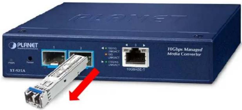

Never pull out the module without pulling the lever or the push bolts on the module. Directly pulling out the module with force could damage the module and SFP module slot of the device.
3. MEDIA CONVERTER MANAGEMENT
This chapter explains the methods that you can use to configure management access to the 10G Managed Media Converter. It describes the types of management applications and the communication and management protocols that deliver data between your management device (workstation or personal computer) and the system. It also contains information about port connection options.
This chapter covers the following topics:
- Requirements
■ Management Access Overview
■ Administration SSH Command Line
■ Web Management Access
■ SNMP Access
■ Standards, Protocols, and Related Reading
3.1 Requirements
■ Workstations running Windows 7/8/10/11, macOS 10.14 or later, Linux, UNIX or other platforms are compatible with TCP/IP protocols.
■ Workstation is installed with Ethernet NIC (Network Interface Card)
■ Ethernet Port connection
- Network cables -- Use standard network (UTP) cables with RJ45 connectors.
■ The Workstation above is installed with the up-to-date Web browser

It is recommended to use the latest version of a modern web browser, such as Google Chrome, Mozilla Firefox, Microsoft Edge, or Apple Safari, to access the 10G Managed Media Converter.
3.2 Management Access Overview
The 10G Managed Media Converter gives you the flexibility to access and manage it using any or all of the following methods:
■ An administration console
■ Web browser interface
■ An external SNMP-based network management application
The administration console and Web browser interface support are embedded in the 10G Managed Media Converter software and are available for immediate use. Each of these management methods has their own advantages. Table 3-1 compares the three management methods.
| Method | Advantages | Disadvantages |
| Command line Interface | Text-basedUse easily acquired telnet or SSH software such as Tera Term or PuttySecure | Modem connection may prove to be unreliable or slow |
| Web Browser | Ideal for configuring the media converter remotelyCompatible with all popular browsersCan be accessed from any locationMost visually appealing | Security can be compromised (hackers need only know the IP address and subnet mask)May encounter lag times on poor connections |
| SNMP Agent | Communicates with media converter functions at the MIB levelBased on open standards | Requires SNMP manager softwareLeast visually appealing of all three methodsSome settings require calculationsSecurity can be compromised (hackers need only know the community name) |
Table 3-1: Comparison of Management Methods
3.3 CLI Mode Management
There are two ways for CLI mode management, remote SSH and telnet. Remote SSH and telnet are IP-based protocols, their operations are the same.
The command line user interface is for performing system administration, such as displaying statistics or changing option settings. When this method is used, you can access the 10G Managed Media Converter remote telnet interface from personal computer or workstation in the same Ethernet environment as long as you know the current IP address of the Managed Switch.

For security reason, the SSH and Telnet protocol is disabled as default setting.
3.3.1 Remote SSH Login
The 10G Managed Media Converter also supports SSHv2 for remote management. The 10G Managed Media Converter asks for user name and password for remote login when using SSHv2 client software; please use "admin" for both username and password.
Default IP address: 192.168.0.100
Username: admin
Password: admin
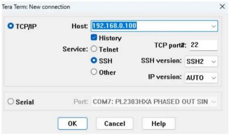
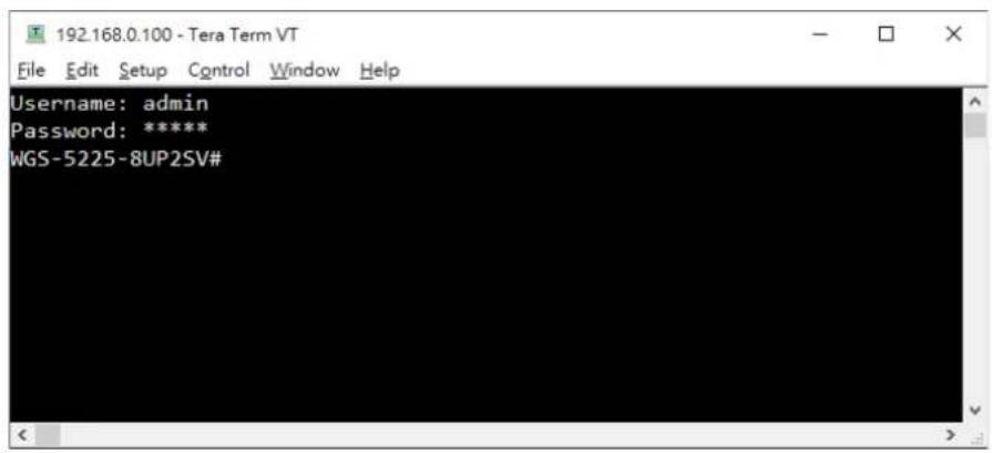
Figure 3-1: 10G Managed Media Converter SSHv2 Login Screen
The user can now enter commands to manage the 10G Managed Media Converter. For a detailed description of the commands, please refer to the following chapters.

- For security reason, please change and memorize the new password after this first setup.
- Only accept command in lowercase letter under console interface.
3.3.2 Configuring IP Address
The 10G Managed Media Converter is shipped with default IP address shown below:
IP Address: 192.168.0.100
Subnet Mask: 255.255.255.0
To check the current IP address or modify a new IP address for the 10G Managed Media Converter, please use the procedure as follows:
■ Display of the Current IP Address
-
At the “#” prompt, enter “show ip”.
-
The screen displays the current IP address shown in Figure 3-2.
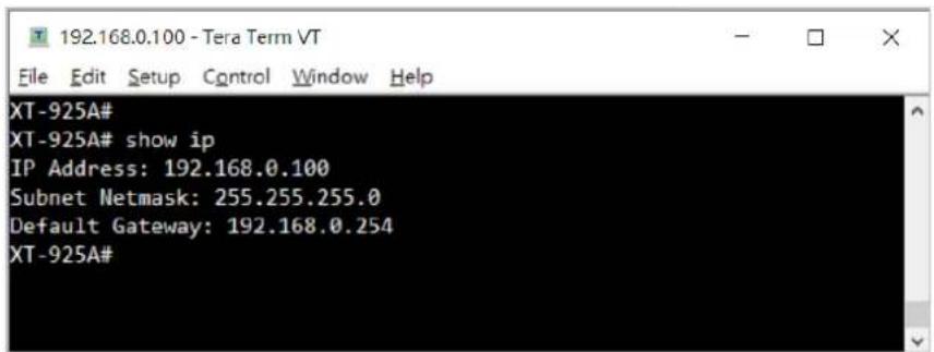
Figure 3-2: IP Information Screen
■ Configuration of the IP Address
- At the “#” prompt, enter the following command and press
as shown in following.
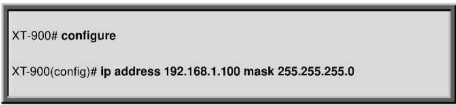
The previous command would apply the following settings for the 10G Managed Media Converter.
IP Address: 192.168.1.100
Subnet Mask: 255.255.255.0
- Repeat step 1 to check if the IP address has changed.
3.3.3 Storing the Current Switch Configuration
At the “#” prompt, enter the following command and press
# copy running-config startup-config
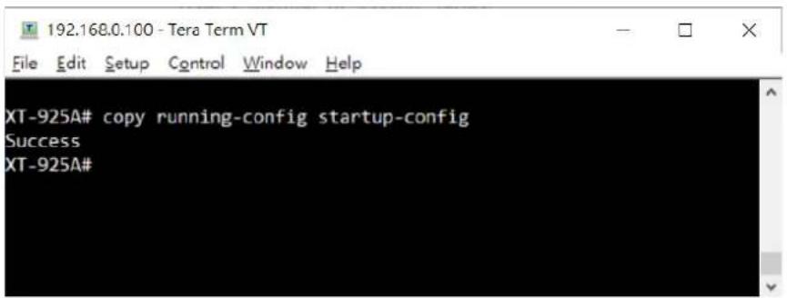
Figure 6-4: Saving Current Configuration Command Screen
If the IP is successfully configured, the 10G Managed Media Converter will apply the new IP address setting immediately. You can access the Web interface of the 10G Managed Media Converter through the new IP address.
3.4 Web Management
The 10G Managed Media Converter offers management features that allow users to manage the 10G Managed Media Converter from anywhere on the network through a standard browser such as Microsoft Internet Explorer. After you set up your IP address for the 10G Managed Media Converter, you can access the 10G Managed Media Converter's Web interface applications directly in your Web browser by entering the IP address of the 10G Managed Media Converter.
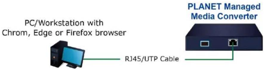
Figure 3-3: Web Management Connection
You can then use your Web browser to list and manage the 10G Managed Media Converter configuration parameters from one central location, just as if you were directly connected to the 10G Managed Media Converter's console port. Web Management requires either the latest version of a modern web browser, such as Google Chrome, Mozilla Firefox, Microsoft Edge, or Apple Safari,

The following web screen uses XT-925A as a representative.
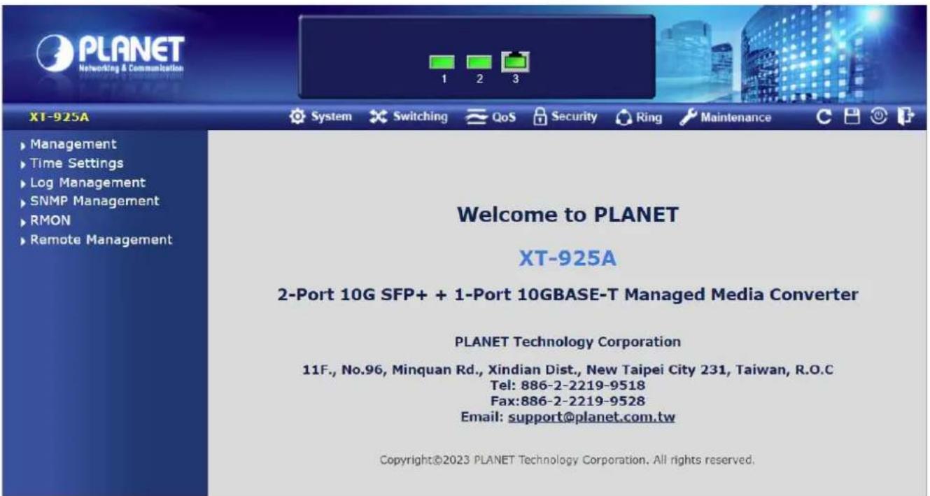
Figure 3-4: Web Main Screen of 10G Managed Media Converter
3.5 SNMP-based Network Management
You can use an external SNMP-based application to configure and manage the 10G Managed Media Converter, such as SNMP Network Manager, MIB browser or What's Up Gold. This management method requires the SNMP agent on the media converter and the SNMP Network Management Station to use the same community string. This management method, in fact, uses two community strings: the get community string and the set community string. If the SNMP Network management Station only knows the set community string, it can read and write to the MIBs. However, if it only knows the get community string, it can only read MIBs. The default gets and sets community strings for the 10G Managed Media Converter are public.
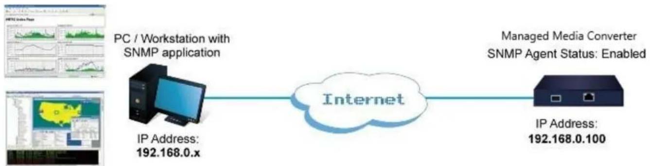
flowchart
graph LR
    A["IP Address: 192.168.0.x"] --> B["Internet"]
    C["PC / Workstation with SNMP application"] --> B
    D["Managed Media Converter SNMP Agent Status: Enabled"] --> B
    E["IP Address: 192.168.0.100"] --> B
Figure 3-5: SNMP Management
3.6 PLANET Smart Discovery Utility
For easily listing the 10G Managed Media Converter in your Ethernet environment, the Planet Smart Discovery Utility is an ideal solution. The following installation instructions are to guide you to running the Planet Smart Discovery Utility.
- Download the PLANET Smart Discovery Utility from PLANET Official Website.
- Deposit the Planet Smart Discovery Utility in administrator PC.
- Run this utility as the following screen appears.
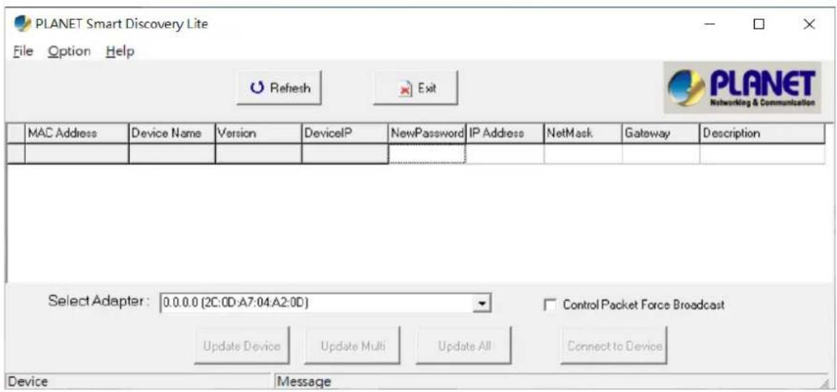
Figure 3-6: Planet Smart Discovery Utility Screen

If there are two LAN cards or above in the same administrator PC, choose a different LAN card by using the "Select Adapter" tool.
- Press the "Refresh" button for the currently connected devices in the discovery list as the screen shows below:
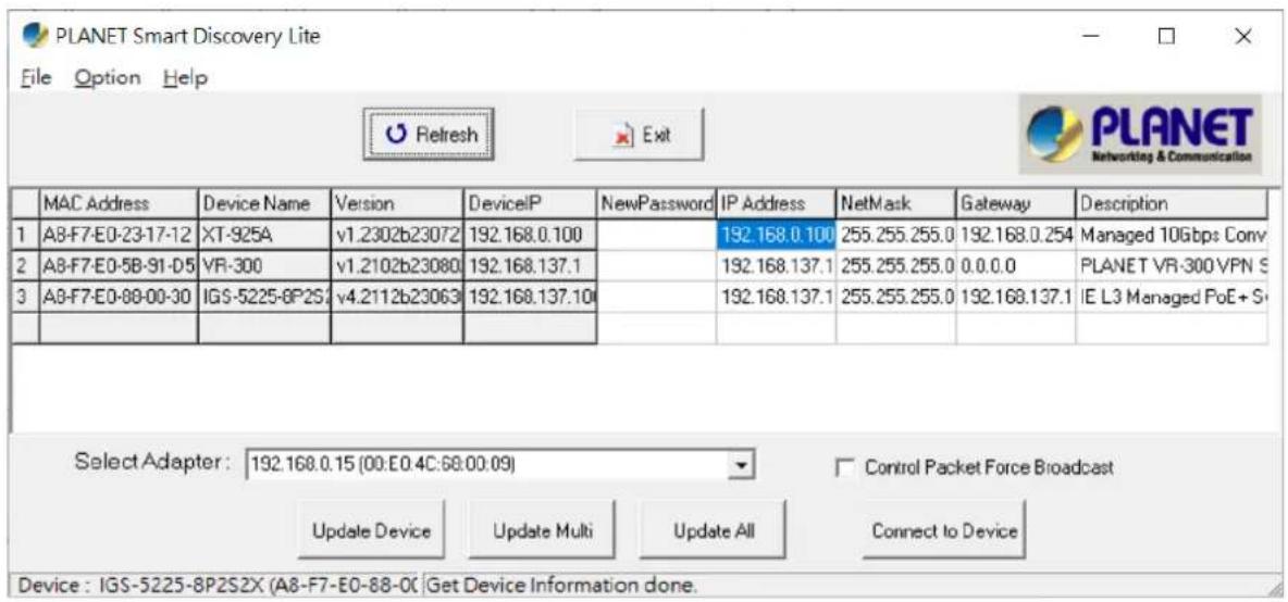
Figure 3-7: Planet Smart Discovery Utility Screen
- This utility shows all necessary information from the devices, such as MAC address, device name, firmware version and device IP subnet address. It can also assign new password, IP subnet address and description for the devices.
- After setup is completed, press the "Update Device", "Update Multi" or "Update All" button to take effect. The meaning of the 3 buttons above are shown below:
■ Update Device: use current setting on one single device.
■ Update Multi: use current setting on choose multi-devices.
■ Update All: use current setting on whole devices in the list.
The same functions mentioned above also can be found in "Option" tools bar.
- To click the "Control Packet Force Broadcast" function, it allows you to assign a new setting value to the Web Smart Media converter under a different IP subnet address.
- Press the "Connect to Device" button and the input username/password in web login screen and the web main screen appears in Figure 3-4.
- Press the "Exit" button to shut down the Planet Smart Discovery Utility.
This section introduces the configuration and functions of the Web-based management.
About Web-based Management
The Managed Media Converter offers management features that allow users to manage the Managed Media Converter from anywhere on the network through a standard browser such as Microsoft Internet Explorer.
The Web-based Management supports Microsoft Edge, Google Chrome and Firefox. It is based on Java Applets with an aim to reduce network bandwidth consumption, enhance access speed and present an easy viewing screen.
The Managed Media Converter can be configured through an Ethernet connection, making sure the manager PC must be set to the same IP subnet address as the Managed Media Converter.
For example, the default IP address of the Managed Media Converter is 192.168.0.100, then the manager PC should be set to 192.168.0.x (where x is a number between 1 and 254, except 100), and the default subnet mask is 255.255.255.0.
If you have changed the default IP address of the Managed Media Converter to 192.168.1.1 with subnet mask 255.255.255.0 via console, then the manager PC should be set to 192.168.1.x (where x is a number between 2 and 254) to do the relative configuration on manager PC.
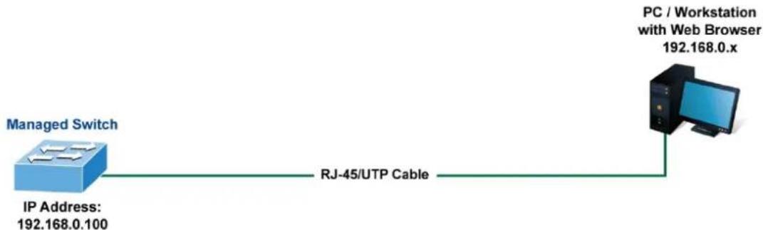
flowchart
graph LR
    A["Managed Switch\nIP Address: 192.168.0.100"] -->|RJ-45/UTP Cable| B["PC / Workstation with Web Browser 192.168.0.x"]
Figure 4-1-1 Web Management
■ Logging on the media converter
- Use Microsoft Edge or Google Chrome Web browser. Enter the factory-default IP address to access the Web interface. The factory-default IP address is as follows:
http://192.168.0.100
- When the following login screen appears, please enter the default username "admin" with password "admin" (or the username/password you have changed via console) to log in the main screen of Managed Media Converter. The login screen in Figure 4-1-2 appears.
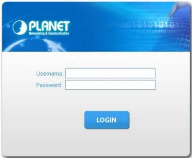
Figure 4-1-2 Login screen
Default User Name: admin
Default Password: admin
After entering the username and password, the main screen appears as Figure 4-1-3 shows.
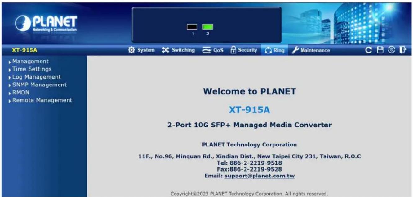
Figure 4-1-3 Default Main Page
Now, you can use the Web management interface to continue the management or manage the Managed Media Converter via Web interface. The Media Converter Menu on the left of the web page lets you access all the commands and statistics the Managed Media Converter provides.

It is recommended to use Microsoft Edge or Google Chrome to access Managed Media Converter.
The changed IP address takes effect immediately after clicking on the Save button. You need to use the new IP address to access the Web interface afterwards.

For security reason, please change and memorize the new password after the first setup.
■ Only accept command in lowercase letter under command line interface.
4.1 Main Web Page
The Managed Media Converter provides a Web-based browser interface for configuring and managing it. This interface allows you to access the Managed Media Converter using the Web browser of your choice. This chapter describes how to use the Managed Media Converter's Web browser interface to configure and manage it.
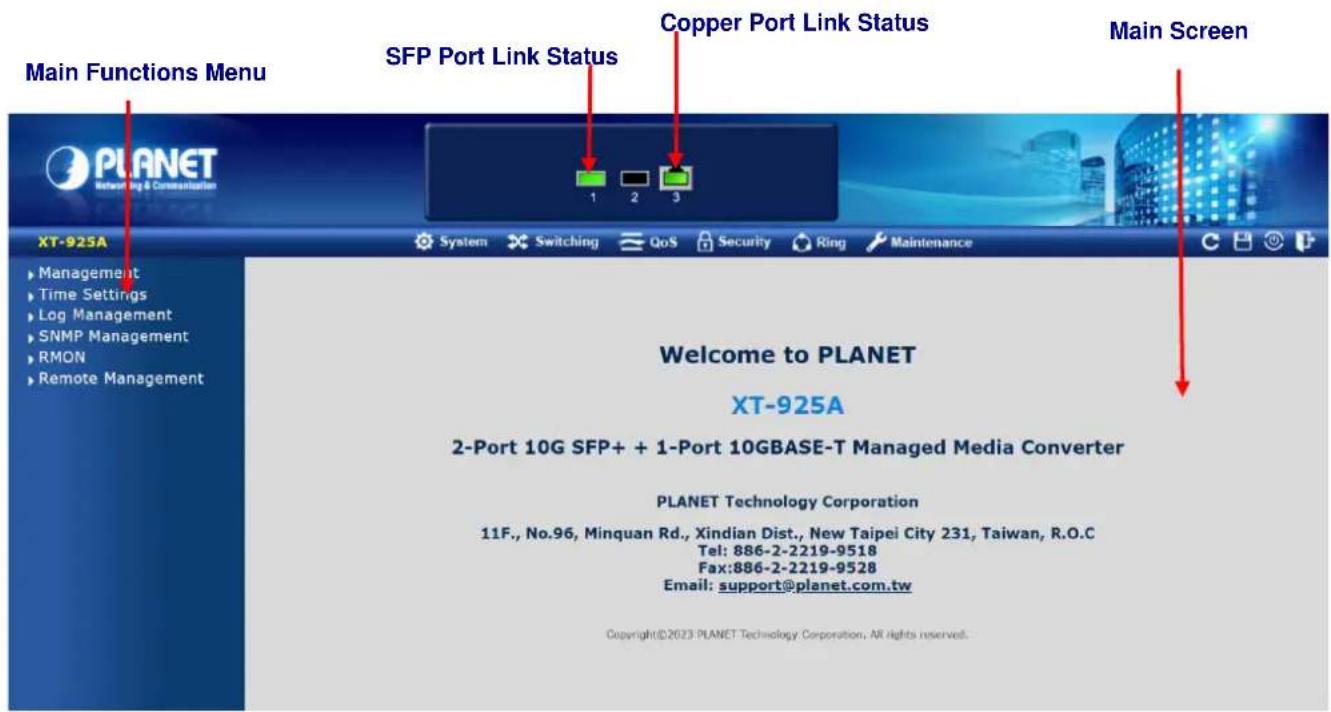
Figure 4-1-4 Main Page
Panel Display
The Web agent displays an image of the Managed Media Converter's ports. The Mode can be set to display different information for the ports, including Link up or Link down. Clicking on the image of a port opens the Port Statistics page. The port states are illustrated as follows:
State
RJ45 Ports
SFP Ports
Disabled


Down


Link


Main Menu
By using the onboard Web agent, you can define system parameters, manage and control the Managed Media Converter, and all its ports, or monitor network conditions. Via the Web-Management, the administrator can set up the Managed Media Converter by selecting the functions those listed in the Main Function. The screen in Figure 4-1-5 appears.
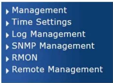
Figure 4-1-5 Managed Media Converter Main Functions Menu
Buttons

: Click to save changes or reset to default.

Click to log out the Managed Media Converter.

Click to reboot the Managed Media Converter.

: Click to refresh the page.
4.1.1 Save Button
This save button allows you to save the running/startup/backup configuration or reset media converter in default parameter. The screen in Figure 4-1-6 appears.

Figure 4-1-6 Save Button Screenshot
The page includes the following fields:
| Object Description | |
| • Save Configuration to FLASH | Click to save the configuration. For more detailed information, please refer to chapter 4.1.2 |
4.1.2 Configuration Manager
The system file folder contains configuration settings. The screen in Figure 4-1-7 appears.
Save Configuration
| Source File | Running configurationStartup configurationBackup configuration |
| Destination File | Startup configurationBackup configuration |
Apply
Figure 4-1-7 Save Button Screenshot
The page includes the following fields:
| Object Description | |
| • Running Configuration | Refers to the running configuration sequence use in the media converter.In media converter, the running configuration file stores in the RAM. In the current version, the running configuration sequence running-config can be saved from the RAM to FLASH by saving “Source File = Running Configuration” to “Destination File = Startup Configuration”, so that the running configuration sequence becomes the startup configuration file, which is called configuration save.To prevent illicit file upload and easier configuration, media converter mandates the name of running configuration file to be running-config. |
| • Startup Configuration | Refers to the configuration sequence used in media converter startup beganup configuration file stores in nonvolatile storage, corresponding to the so-called configuration save. If the device supports multi-config file, name the configuration file to be .cfg file, the default is startup.cfg.If the device does not support multi-config file, mandates the name of startup configuration file to be startup-config. |
| • Backup Configuration | The backup configuration is empty in FLASH; please save the backup configuration first by “Maintenance > Backup Manager”. |
Buttons
Apply
: Click to save configuration.
4.1.2.1 Saving Configuration
In the Managed Media Converter, the running configuration file stores in the RAM. In the current version, the running configuration sequence of running-config can be saved from the RAM to FLASH by "Save Configurations to FLASH" function, so that the running configuration sequence becomes the startup configuration file, which is called configuration save.
To save all applied changes and set the current configuration as a startup configuration. The startup-configuration file will be loaded automatically across a system reboot.
- Click "Save Configuration" on the main menu on the left.
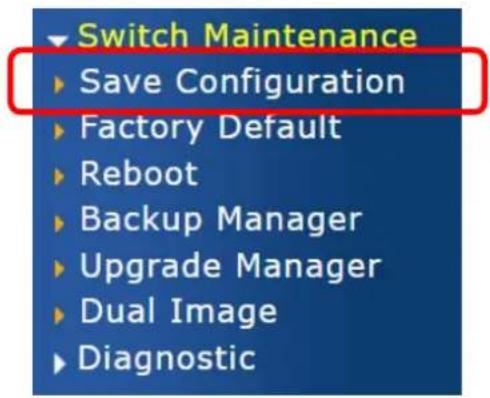
- Select "Running Configuration" as the Source File and "Startup Configuration" as the Destination File.
Save Configuration
| Source File | Running configurationStartup configurationBackup configuration |
| Destination File | Startup configurationBackup configuration |
Apply
- Press "Apply" button to save running configuration to startup configuration.
4.2 System
Use the System menu items to display and configure basic administrative details of the Managed Media Converter. Under the system, the following topics are provided to configure and view the system information. This section has the following items:
| 4.2.1 Management | |
| □ System Information | The system information is provided here. |
| □ IP Configuration | Configure the managed media converter's IP information on this page. |
| □ IPv6 Configuration | Configure the managed media converter's IPv6 information on this page. |
| □ User Configuration | Configure new user name and password on this page. |
| 4.2.2 Time Settings | |
| □ System Time | Configure system time settings on this page. |
| □ SNTP Settings | Configure SNTP settings on this page. |
| 4.2.3 Log Management | |
| □ Logging Service | Configure logging service settings on this page. |
| □ Local Logging | Configure local logging settings on this page. |
| □ Remote Syslog | Configure remote syslog settings on this page. |
| □ Logging Message | Configure logging message settings on this page. |
| 4.2.4 SNMP Management | |
| □ SNMP Setting | Configure System Time settings on this page. |
| □ SNMP Community | Configure SNTP settings on this page. |
| □ SNMP View | Configure System Time settings on this page. |
| □ SNMP Access Group | Configure SNTP settings on this page. |
| □ SNMP User | Configure System Time settings on this page. |
| □ SNMPv1, 2 Notification Recipients | Configure SNTP settings on this page. |
| □ SNMPv3 Notification Recipients | Configure System Time settings on this page. |
| □ SNMP Engine ID | Configure SNTP settings on this page. |
| □ SNMP Remote Engine ID | Configure System Time settings on this page. |
| 4.2.5 RMON | |
| □ RMON Statistics | Configure RMON statistics settings on this page. |
| □ RMON Event | Configure RMON event settings on this page. |
| □ RMON Event Log | Configure RMON event log settings on this page. |
| □ RMON Alarm | Configure RMON alarm settings on this page. |
| □ RMON History | Configure RMON history settings on this page. |
| □ RMON History Log | Configure RMON history log settings on this page. |
| 4.2.6 Remote Management | |
| □ Remote NMS Configuration | Configure Remote NMS Configuration settings on this page. |
4.2.1 Management
4.2.1.1 System Information
The System Info page provides information for the current device information. System Info page helps the administrator to identify the hardware MAC address, software version and system uptime. The screens are shown in Figure 4-2-1 and Figure 4-2-2.
| Information Name | Information Value |
| System Name | Edit XT-915A |
| System Location | Edit Default Location |
| System Contact | Edit Default Contact |
| MAC Address | A8:F7:E0:22:33:66 |
| SerialNo | AA504023700299 |
| IP Address | 192.168.0.101 |
| Subnet Mask | 255.255.255.0 |
| Gateway | 192.168.0.254 |
| Loader Version | 2011.12.(4.0.3.55179) |
| Loader Date | Apr 19 2023 - 10:03:30 |
| Firmware Version | v1.2302b230726 |
| Firmware Date | Jul 26 2023 - 11:02:08 |
| System Object ID | 1.3.6.1.4.1.10456.2.643 |
| System Up Time | 0 days, 1 hours, 44 mins, 26 secs |
| PCB/HW Version | V1 |
Figure 4-2-1 System Information Screenshot
The page includes the following fields:
| Object Description | |
| System Name | Display the current system name |
| System Location | Display the current system location |
| System Contact | Display the current system contact |
| MAC Address | The MAC address of this Managed Media Converter. |
| Serial No | Each media converter has its own serial number. |
| IP Address | The IP address of this Managed Media Converter. |
| Subnet Mask | The subnet mask of this Managed Media Converter. |
| Gateway | The gateway of this Managed Media Converter. |
| Loader Version | The loader version of this Managed Media Converter. |
| Loader Date | The loader date of this Managed Media Converter. |
| Firmware Version | The firmware version of this Managed Media Converter. |
| Firmware Date | The firmware date of this Managed Media Converter. |
| System Object ID | The system object ID of the Managed Media Converter. |
| System Up Time | The period of time the device has been operational. |
| PCN/HW Version | The hardware version of this Managed Media Converter. |
Buttons
Edit
: Click to edit parameter.
4.2.1.2 IP Configurations
The IP Configuration includes the IP Address, Subnet Mask and Gateway. The configuration column is used to view or change the IP configuration. Fill out the IP Address, Subnet Mask and Gateway for the device. The screens are shown in Figure 4-2-2 and Figure 4-2-3.
IP Address Setting
| Mode | Static DHCP |
| IP Address | 192.168.0.101 |
| Subnet Mask | 255.255.255.0 |
| Gateway | 192.168.0.254 |
| DNS Server 1 | 168.95.1.1 |
| DNS Server 2 | 168.95.192.1 |
Apply
Figure 4-2-2 IP Address Setting Screenshot
The page includes the following fields:
| Object Description | |
| • Mode | Indicates the IP address mode operation. Possible modes are:Static: Enable NTP mode operation.When enabling NTP mode operation, the agent forwards and transfersNTP messages between the clients and the server when they are not onthe same subnet domain.DHCP: Enable DHCP client mode operation.Enable the DHCP client by checking this box. If DHCP fails and theconfigured IP address is zero, DHCP will retry. If DHCP fails and theconfigured IP address is non-zero, DHCP will stop and the configured IPsettings will be used. The DHCP client will announce the configuredSystem Name as hostname to provide DNS lookup. |
| • IP Address | Provide the IP address of this media converter in dotted decimal notation. |
| • Subnet Mask | Provide the subnet mask of this media converter in dotted decimal notation. |
| • Gateway | Provide the IP address of the router in dotted decimal notation. |
| • DNS Server 1/2 | Provide the IP address of the DNS Server in dotted decimal notation. |
Buttons
Apply
: Click to apply changes.
IP Information
| Information Name | Information Value |
| DHCP State | Disable |
| Static IP Address | 192.168.0.101 |
| Static Subnet Mask | 255.255.255.0 |
| Static Gateway | 192.168.0.254 |
| Static DNS Server 1 | 168.95.1.1 |
| Static DNS Server 2 | 168.95.192.1 |
Figure 4-2-3 IP Information Screenshot
The page includes the following fields:
| Object Description | |
| DHCP State | Display the current DHCP state. |
| IP Address | Display the current IP address. |
| Subnet Mask | Display the current subnet mask. |
| Gateway | Display the current gateway. |
| DNS Server 1/2 | Display the current DNS server. |
4.2.1.3 IPv6 Configuration
The IPv6 Configuration includes Auto Configuration, IPv6 Address and Gateway. The configured column is used to view or change the IPv6 configuration. Fill out the Auto Configuration, IPv6 Address and Gateway for the device. The screens are shown in Figure 4-2-4 and Figure 4-2-5.
IPv6 Address Setting
| Auto Configuration | ○ Disable ○ Enable |
| IPv6 Address | / 0 |
| Gateway | |
| DHCPv6 Client | ○ Disable ○ Enable |
Apply
Figure 4-2-4 IPv6 Address Setting Screenshot
The page includes the following fields:
| Object Description | |
| • Auto Configuration | Enable IPv6 auto-configuration by checking this box.If it fails, the configured IPv6 address is zero. The router may delay responding to a router solicitation for a few seconds; the total time needed to complete auto-configuration can be significantly longer. |
| • IPv6 Address | Provide the IPv6 address of this media converter.IPv6 address is in 128-bit records represented as eight fields of up to four hexadecimal digits with a colon separating each field ():. For example,'fe80::215:c5ff:fe03:4dc7'.The symbol ‘::’ is a special syntax that can be used as a shorthand way of representing multiple 16-bit groups of contiguous zeros; but it can only appear once. It also uses the following legally IPv4 address. For example, ':192.1.2.34'.Provide the IPv6 Prefix of this media converter. The allowed range is from 1 through 128. |
| • Gateway | Provide the IPv6 gateway address of this media converter.IPv6 address is in 128-bit records represented as eight fields of up to four hexadecimal digits with a colon separating each field ():. For example,'fe80::215:c5ff:fe03:4dc7'. |
| • DHCPv6 Client | To enable this Managed Media Converter to accept a configuration from a Dynamic Host Configuration Protocol version 6 (DHCPv6) server. By default, the Managed Media Converter does not perform DHCPv6 client actions.DHCPv6 clients request the delegation of long-lived prefixes that they can push to individual local hosts. |
Buttons
Apply
: Click to apply changes.
| Information Name | Information Value |
| Auto Configuration | Enabled |
| IPv6 In Use Address | fe80::2e0:4cff:fe00:0 / 64 |
| IPv6 In Use Router | :: |
| IPv6 Static Address | fe80::2e0:4cff:fe00:0 / 0 |
| IPv6 Static Router | :: |
| DHCPv6 Client | Disabled |
Figure 4-2-5 IPv6 Information Screenshot
The page includes the following fields:
| Object Description | |
| • Auto Configuration | Display the current auto configuration state |
| • IPv6 In Use Address | Display the current IPv6 in-use address |
| • IPv6 In Use Router | Display the current in-use gateway |
| • IPv6 Static Address | Display the current IPv6 static address |
| • IPv6 Static Router | Display the current IPv6 static gateway |
| • DHCPv6 Client | Display the current DHCPv6 client status |
4.2.1.4 User Configuration
This page provides an overview of the current users and privilege type. Currently the only way to login as another user on the Web server is to close and reopen the browser. After the setup is completed, please press "Apply" button to take effect. Please login Web interface with a new user name and password; the screens are shown in Figure 4-2-6 and Figure 4-2-7.
New User
| User Name | Password Type | Password | Retype Password | Privilege Type |
| Clear Text √ | Admin √ |
Apply
Figure 4-2-6 Local User Information Screenshot
The page includes the following fields:
| Object Description | |
| •Username | The name identifying the user.Maximum length: 32 characters;Maximum number of users:8 |
| •Password Type | The password type for the user. |
| •Password | Enter the user's new password here.(Range: 0-32 characters plain text, case sensitive) |
| •Retype Password | Please enter the user's new password here again to confirm. |
| •Privilege Type | The privilege type for the user.Options:AdminUserOther |
Buttons
Apply
: Click to apply changes.
| User Name | Password Type | Privilege Type | Privilege Value | Modify |
| admin | Encrypted | Admin | 15 |
Figure 4-2-7 Local User Screenshot
The page includes the following fields:
| Object Description | |
| •Username | Display the current username |
| •Password Type | Display the current password type |
| •Privilege Type | Display the current privilege type |
| •Modify | Click to modify the local user entryDelete: Delete the current user |
4.2.2 Time Settings
4.2.2.1 System Time
Configure System time on this page. You can specify SNTP Servers and set GMT Time zone. The SNTP Configuration screens are shown in Figure 4-2-8 and Figure 4-2-9.
System Time Setting
| Enable SNTP | Disable Enable |
| Manual Time | Year 2000 Month Jan Day 1 Hours 0 Minutes 0 Seconds 0 |
| Time Zone | None |
| Daylight Saving Time | Disable |
| Daylight Saving Time Offset | 0 (1 - 1440) Minutes |
| Recurring From | Day Sun Week 1 Month Jan Hours 0 Minutes 0 |
| Recurring To | Day Sun Week 1 Month Jan Hours 0 Minutes 0 |
| Non-recurring From | Year 2000 Month Jan Date 1 Hours 0 Minutes 0 |
| Non-recurring To | Year 2000 Month Jan Date 1 Hours 0 Minutes 0 |
Apply
Figure 4-2-8 System Time Setting Screenshot
The page includes the following fields:
| Object Description | |
| Enable SNTP | Enabled: Enable SNTP mode operation.When enabling SNTP mode operation, the agent forwards and transfersSNTP messages between the clients and the server when they are noton the same subnet domain.Disabled: Disable SNTP mode operation. |
| Manual Time | To set time manually.Year - Select the starting Year.Month - Select the starting month.Day - Select the starting day.Hours - Select the starting hour.Minutes - Select the starting minute.Seconds - Select the starting seconds. |
| Time Zone | Allows to select the time zone according to the current location of mediaconverter. |
| Daylight Saving Time | This is used to set the clock forward or backward according to the configurationsset below for a defined Daylight Saving Time duration. Select 'Disable' to disablethe Daylight Saving Time configuration. Select 'Recurring' and configure the Daylight Saving Time duration to repeat the configuration every year. Select 'Non-Recurring' and configure the Daylight Saving Time duration for single time configuration. (Default: Disabled). |
| Daylight Saving Time Offset | Enter the number of minutes to add during Daylight Saving Time. (Range: 1 to 1440 ) |
| Recurring From | Week - Select the starting week number.Day - Select the starting day.Month - Select the starting month.Hours - Select the starting hour.Minutes - Select the starting minute. |
| Recurring To | Week - Select the starting week number.Day - Select the starting day.Month - Select the starting month.Hours - Select the starting hour.Minutes - Select the starting minute. |
| Non-recurring From | Week - Select the starting week number.Day - Select the starting day.Month - Select the starting month.Hours - Select the starting hour.Minutes - Select the starting minute. |
| Non-recurring To | Week - Select the starting week number.Day - Select the starting day.Month - Select the starting month.Hours - Select the starting hour.Minutes - Select the starting minute. |
Buttons
Apply
: Click to apply changes.
System Time Informations
| Information Name | Information Value |
| Current Date/Time | 09:13:10 DFL(UTC+8) Jan 01 2000 |
| SNTP | Disabled |
| Time zone | UTC+8 |
| Daylight Saving Time | Disabled |
| Daylight Saving Time Offset | |
| From | |
| To |
Figure 4-2-9 Time Information Screenshot
The page includes the following fields:
| Object Description | |
| • Current Data/Time | Display the current data/time |
| • SNTP | Display the current SNTP state |
| • Time Zone | Display the current time zone |
| • Daylight Saving Time | Display the current daylight saving time state |
| • Daylight Saving Time Offset | Display the current daylight saving time offset state |
| • From | Display the current daylight saving time from |
| • To | Display the current daylight saving time to |
4.2.2.2 SNTP Server Settings
SNTP is an acronym for Simple Network Time Protocol, a network protocol for synchronizing the clocks of computer systems. The SNTP Server Configuration screens are shown in Figure 4-2-10 and Figure 4-2-11.
SNTP Server Settings
| SNTP Server Address | ( X.X.X. or Hostname) | |
| Server Port | 123 | ( 1 - 65535 | Default : 123 ) |
Apply
Figure 4-2-10 SNTP Setup Screenshot
The page includes the following fields:
| Object Description | |
| • SNTP Server Address | Type the IP address or domain name of the SNTP server |
| • Server Port | Type the port number of the SNTP |
Buttons
Apply
: Click to apply changes.
| Information Name | Information Value |
| SNTP Server Address | time.nist.gov |
| SNTP Server Port | 123 |
Figure 4-2-11 SNTP Server Information Screenshot
The page includes the following fields:
| Object Description | |
| • SNTP Server Address | Display the current SNTP server address |
| • Server Port | Display the current SNTP server port |
4.2.3 Log Management
The Managed Media Converter log management is provided here. The local logs allow you to configure and limit system messages that are logged to flash or RAM memory. The default is for event levels 0 to 3 to be logged to flash and levels 0 to 6 to be logged to RAM. The following table lists the event levels of the Managed Media Converter:
| Level | Severity Name | Description |
| 7 | Debug | Debugging messages |
| 6 | Informational | Informational messages only |
| 5 | Notice | Normal but significant condition, such as cold start |
| 4 | Warning | Warning conditions (e.g., return false, unexpected return) |
| 3 | Error | Error conditions (e.g., invalid input, default used) |
| 2 | Critical | Critical conditions (e.g., memory allocation, or free memory error - resource exhausted) |
| 1 | Alert | Immediate action needed |
| 0 | Emergency | System unusable |
4.2.3.1 Logging Service
The media converter system local log information is provided here. The local Log screens in Figure 4-2-12 and Figure 4-2-13 appear.

Figure 4-2-12 Logging Settings Screenshot
The page includes the following fields:
| Object | Description |
| • Logging Service | Enabled: Enable logging service operation. |
| Disabled: Disable logging service operation. |
Buttons
Apply
: Click to apply changes.
| Information Name | Information Value |
| Logging Service | enabled |
Figure 4-2-13 Logging Information Screenshot
The page includes the following fields:
| Object | Description |
| • Logging Service | Display the current logging service status |
4.2.3.2 Local Logging
The media converter system local log information is provided here. The local Log screens in Figure 4-2-14 and Figure 4-2-15 appear.
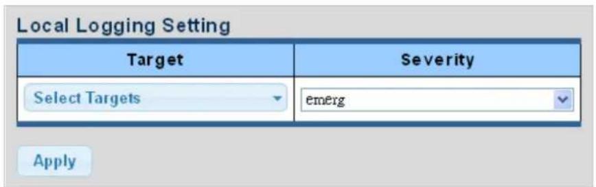
Figure 4-2-14 Local Log Target Setting Screenshot
The page includes the following fields:
| Object Description | |
| • Target | The target of the local log entry. The following target types are supported:Buffered: Target the buffer of the local log.File: Target the file of the local log. |
| • Severity | The severity of the local log entry. The following severity types are supported:emerg: Emergency level of the system unstable for local log.alert: Alert level of the immediate action needed for local log.crit: Critical level of the critical conditions for local log.error: Error level of the error conditions for local log.warning: Warning level of the warning conditions for local log.notice: Notice level of the normal but significant conditions for local log.info: Informational level of the informational messages for local log.debug: Debug level of the debugging messages for local log. |
Buttons
Apply
: Click to apply changes.
| Status | Target | Severity | Action |
| enabled | buffered | emerg, alert, crit, error, warning, notice | Delete |
Figure 4-2-15 Local Log Setting Status Screenshot
The page includes the following fields:
| Object Description | |
| • Status | Display the current local log state |
| • Target | Display the current local log target |
| • Severity | Display the current local log severity |
| • Action | Delete: Delete the current status |
4.2.3.3 Remote Syslog
Configure remote syslog on this page. The Remote Syslog page allows you to configure the logging of messages that are sent to syslog servers or other management stations. You can also limit the event messages sent to only those messages below a specified level.
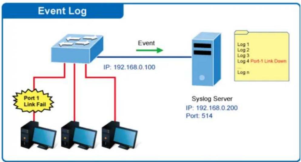
flowchart
graph TD
    A["Port 1 Link Fail"] --> B["Router"]
    B --> C["Syslog Server"]
    C --> D["Port: 514"]
    B -->|IP: 192.168.0.100| E["Event"]
    C -->|Log 1, Log 2, Log 3, Log 4 Port-1 Link Down, ... Log n| F["End"]
The Remote Syslog screens in Figure 4-2-16 and Figure 4-2-17 appear.

Figure 4-2-16 Remote Log Target Screenshot
The page includes the following fields:
| Object Description | |
| • Server Address | Provide the remote syslog IP address of this media converter. |
| • Server Port | Provide the port number of remote syslog server.Default Port no.: 514 |
| • Severity | The severity of the local log entry. The following severity types are supported:■ emerg: Emergency level of the system unstable for local log.■ alert: Alert level of the immediate action needed for local log.■ crit: Critical level of the critical conditions for local log.■ error: Error level of the error conditions for local log.■ warning: Warning level of the warning conditions for local log.■ notice: Notice level of the normal but significant conditions for local log.■ info: Informational level of the informational messages for local log.■ debug: Debug level of the debugging messages for local log. |
| • Facility | Local0~7: local user 0~7 |
Buttons
Apply
: Click to apply changes.

Figure 4-2-17 Remote Log Setting Status Screenshot
The page includes the following fields:
| Object Description | |
| • Status | Display the current remote syslog state |
| • Server Info | Display the current remote syslog server information |
| • Severity | Display the current remote syslog severity |
| • Facility | Display the current remote syslog facility |
| • Action | Delete: Delete the remote server entry |
4.2.3.4 Logging Message
The media converter log view is provided here. The Log View screens in Figure 4-2-18, Figure 4-2-19 and Figure 4-2-20 appear.
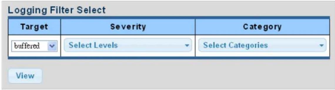
Figure 4-2-18 Log Information Select Screenshot
The page includes the following fields:
| Object Description | |
| • Target | The target of the log view entry. The following target types are supported:Buffered: Target the buffered of the log view.File: Target the file of the log view. |
| • Severity | The severity of the log view entry. The following severity types are supported:emerg: Emergency level of the system unstable for log view.alert: Alert level of the immediate action needed for log view.crit: Critical level of the critical conditions for log view.error: Error level of the error conditions for log view.warning: Warning level of the warning conditions for log view.notice: Notice level of the normal but significant conditions for log view.info: Informational level of the informational messages for log view.debug: Debug level of the debugging messages for log view. |
| • Category | The category of the log view includes:AAA, ACL, CABLE_DIAG, DAI, DHCP_SNOOPING, Dot1X, GVRP,IGMP_SNOOPING, IPSG, L2, LLDP, Mirror, MLD_SNOOPING, Platform, PM,Port, PORT_SECURITY, QoS, Rate, SNMP and STP |
Buttons
View
Click to view log.
Logging Information
| Information Name | Information Value |
| Target | buffered |
| Severity | emerg, alert, crit, error, warning, notice |
| Category | AAA, ACL, CABLE_DIAG, DAI, DHCP_SNOOPING, Dot1X, GVRP, IGMP_SNOOPING, IPSG, L2, LLDP, Mirror, MLD_SNOOPING, Platform, PM, Port, PORT_SECURITY, QoS, Rate, SNMP, STP, Security-suite, System, Trunk, VLAN |
| Total Entries | 1 |
Figure 4-2-19 Logging Information Screenshot
The page includes the following fields:
| Object Description | |
| • Target | Display the current log target |
| • Severity | Display the current log severity |
| • Category | Display the current log category |
| • Total Entries | Display the current log entries |
Logging Messages
Clear buffered messages
Refresh
1
| No. | Timestamp | Category | Severity | Message |
| 1 | Jan 01 2000 08:00:19 | Port | notice | Port gi1 link up |
Figure 4-2-20 Logging Messages Screenshot
The page includes the following fields:
| Object Description | |
| • No. | This is the number for logs |
| • Timestamp | Display the time of log |
| • Category | Display the category type |
| • Severity | Display the severity type |
| • Message | Display the log message |
Buttons
Clear
: Click to clear the log.
Refresh
: Click to refresh the log.
4.2.4 SNMP Management
4.2.4.1 SNMP Overview
The Simple Network Management Protocol (SNMP) is an application layer protocol that facilitates the exchange of management information between network devices. It is part of the Transmission Control Protocol/Internet Protocol (TCP/IP) protocol suite. SNMP enables network administrators to manage network performance, find and solve network problems, and plan for network growth.
An SNMP-managed network consists of three key components: Network management stations (NMS's), SNMP agents, Management information base (MIB) and network-management protocol:
Network management stations (NMS's): Sometimes called consoles, these devices execute management applications that monitor and control network elements. Physically, NMS's are usually engineering workstation-caliber computers with fast CPUs, megapixel color displays, substantial memory, and abundant disk space. At least one NMS must be present in each managed environment.
Agents: Agents are software modules that reside in network elements. They collect and store management information such as the number of error packets received by a network element.
Management information base (MIB): A MIB is a collection of managed objects residing in a virtual information store. Collections of related managed objects are defined in specific MIB modules.
Network-management protocol: A management protocol is used to convey management information between agents and NMS's. SNMP is the Internet community's de facto standard management protocol.
SNMP Operations
SNMP itself is a simple request/response protocol. NMS's can send multiple requests without receiving a response.
Get -- Allows the NMS to retrieve an object instance from the agent.
Set -- Allows the NMS to set values for object instances within an agent.
Trap -- Used by the agent to asynchronously inform the NMS of some event. The SNMPv2 trap message is designed to replace the SNMPv1 trap message.
SNMP community
An SNMP community is the group that devices and management stations running SNMP belong to. It helps define where information is sent. The community name is used to identify the group. An SNMP device or agent may belong to more than one SNMP community. It will not respond to requests from management stations that do not belong to one of its communities. SNMP default communities are:
Write = private
Read = public
4.2.4.2 SNMP Setting
Configure SNMP setting on this page. The SNMP System global setting screens in Figure 4-2-21 and Figure 4-2-22 appear.

Figure 4-2-21 SNMP Global Setting Screenshot
The page includes the following fields:
| Object Description | |
| • Status | Indicates the SNMP mode operation. Possible modes are:Enabled: Enable SNMP mode operation.Disabled: Disable SNMP mode operation. |
Buttons
Apply
: Click to apply changes.
| Information Name | Information Value |
| SNMP | Disable |
Figure 4-2-22 SNMP Information Screenshot
The page includes the following fields:
| Object Description | |
| • SNMP | Display the current SNMP status |
4.2.4.3 SNMP Community
Configure SNMP Community on this page. The SNMP Community screens in Figure 4-2-23 and Figure 4-2-24 appear.
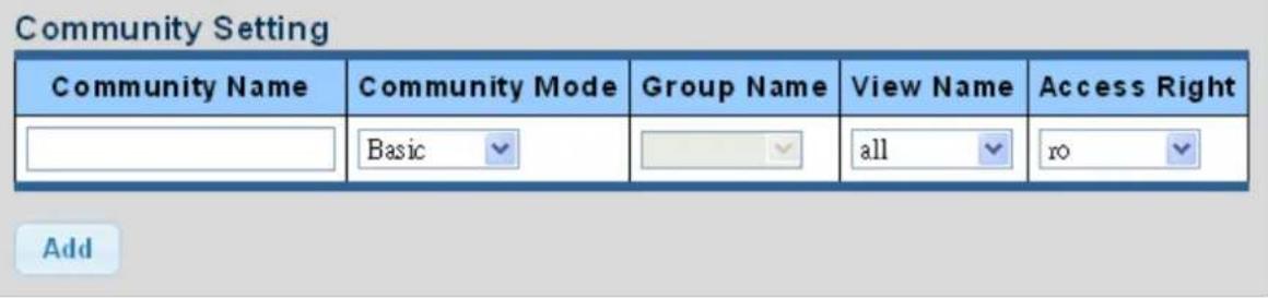
Figure 4-2-23 Community Setting Screenshot
The page includes the following fields:
| Object Description | |
| Community Name | Indicates the community read/write access string to permit access to SNMP agent.The allowed string length is 0 to 16. |
| Community Mode | Indicates the SNMP community supported mode. Possible versions are:■ Basic: Set SNMP community mode supported version 1 and 2c.■ Advanced: Set SNMP community mode supported version 3. |
| Group Name | A string identifying the group name that this entry should belong to.The allowed string length is 1 to 16. |
| View Name | A string identifying the view name that this entry should belong to.The allowed string length is 1 to 16. |
| Access Right | Indicates the SNMP community type operation. Possible types are:RO=Read-Only: Set access string type in read-only mode.RW=Read-Write: Set access string type in read-write mode. |
Buttons
Apply
: Click to apply changes.
| Community Name | Group Name | View Name | Access Right | Action |
| public | all | rw | Delete |
Figure 4-2-24 Community Status Screenshot
The page includes the following fields:
| Object Description | |
| Community Name | Display the current community type |
| Group Name | Display the current SNMP access group's name |
| View Name | Display the current view name |
| Access Right | Display the current access type |
| Delete | Delete: Delete the community entry |
4.2.4.4 SNMP View
Configure SNMPv3 view table on this page. The entry index keys are View Name and OID Subtree. The SNMPv3 View Table Setting screens in Figure 4-2-25 and Figure 4-2-26 appear.
View Table Setting
| View Name | Subtree OID | Subtree OID Mask | View Type |
| all | included excluded |
Add
Figure 4-2-25 SNMPv3 View Table Setting Screenshot
The page includes the following fields:
| Object Description | |
| • View Name | A string identifying the view name that this entry should belong to.The allowed string length is 1 to 16. |
| • Subtree OID | The OID defining the root of the subtree to add to the named view.The allowed string content is digital number or asterisk (*). |
| • Subtree OID Mask | The bitmask identifies which positions in the specified object identifier are to be regarded as "wildcards" for the purpose of pattern-matching. |
| • View Type | Indicates the view type that this entry should belong to. Possible view type are:included: An optional flag to indicate that this view subtree should be included.excluded: An optional flag to indicate that this view subtree should be excluded.General, if a view entry's view type is 'excluded', it should exist another view entry in which view type is 'included' and its OID subtree oversteps the 'excluded' view entry. |
Buttons
Add
: Click to add a new view entry.
| View Name | Subtree OID | OID Mask | View Type | Action |
| all | 1 | all | included |
Figure 4-2-26 SNMP View Table Status Screenshot
The page includes the following fields:
| Object Description | |
| • View Name | Display the current SNMP view name |
| • Subtree OID | Display the current SNMP subtree OID |
| • OID Mask | Display the current SNMP OID mask |
| • View Type | Display the current SNMP view type |
| • Action | Delete : Delete the view table entry. |
4.2.4.5 SNMP Access Group
Configure SNMPv3 access group on this page. The entry index keys are Group Name, Security Model and Security Level.
The SNMPv3 Access Group Setting screens in Figure 4-2-27 and Figure 4-2-28 appear.
Access Group Setting
| Group Name | Security Model | Security Level | Read View Name | Write View Name | Notify View Name |
| v1 | noauth | all | None | None |
Add
Figure 4-2-27 SNMPv3 Access Group Setting Screenshot
The page includes the following fields:
| Object Description | |
| • Group Name | A string identifying the group name that this entry should belong to.The allowed string length is 1 to 16. |
| • Security Model | Indicates the security model that this entry should belong to.Possible security models are:■ v1: Reserved for SNMPv1.■ v2c: Reserved for SNMPv2c.■ V3: Reserved for SNMPv3 or User-based Security Model (USM) |
| • Security Level | Indicates the security model that this entry should belong to.Possible security models are:■ Noauth: None authentication and none privacy security levels are assigned to the group.■ auth: Authentication and none privacy.■ priv: Authentication and privacy.Note: The Security Level applies to SNNPv3 only. |
| • Read View Name | Read view name is the name of the view in which you can only view the contents of the agent.The allowed string length is 1 to 16. |
| • Write View Name | Write view name is the name of the view in which you enter data and configure the contents of the agent.The allowed string length is 1 to 16. |
| • Notify View Name | Notify view name is the name of the view in which you specify a notify, inform, or trap. |
Buttons
Add
: Click to add a new access entry.
Delete
: Check to delete the entry.

Figure 4-2-28 SNMP View Table Status Screenshot
The page includes the following fields:
| Object Description | |
| • Group Name | Display the current SNMP access group name |
| • Security Model | Display the current security model |
| • Security Level | Display the current security level |
| • Read View Name | Display the current read view name |
| • Write View Name | Display the current write view name |
| • Notify View Name | Display the current notify view name |
| • Action | Delete: Delete the access group entry. |
4.2.4.6 SNMP User
Configure SNMPv3 users table on this page. Each SNMPv3 user is defined by a unique name. Users must be configured with a specific security level and assigned to a group. The SNMPv3 group restricts users to a specific read, write, and notify view. The entry index key is User Name. The SNMPv3 User Setting screens in Figure 4-2-29 and Figure 4-2-30 appear.
User Setting
| User Name | Group | Privilege Mode | Authentication Protocol | Authentication Password | Encryption Protocol | Encryption Key |
| nowth | None | (8~16 chars) | None | (8~16 chars) |
Figure 4-2-29 SNMPv3 Users Configuration Screenshot
The page includes the following fields:
| Object Description | |
| User Name | A string identifying the user name that this entry should belong to.The allowed string length is 1 to 16. |
| Group | The SNMP Access Group. A string identifying the group name that this entry should belong to. |
| Privilege Mode | Indicates the security model that this entry should belong to. Possible security models are:NoAuth: None authentication and none privacy.Auth: Authentication and none privacy.Priv: Authentication and privacy.The value of security level cannot be modified if entry already exists. That means you must first ensure that the value is set correctly. |
| Authentication Protocol | Indicates the authentication protocol that this entry should belong to. Possible authentication protocols are:None: None authentication protocol.MD5: An optional flag to indicate that this user using MD5 authentication protocol.SHA: An optional flag to indicate that this user using SHA authentication protocol.The value of security level cannot be modified if entry already exists. That means you must first ensure that the value is set correctly. |
| Authentication Password | A string identifying the authentication pass phrase. For both MD5 and SHA authentication protocols, the allowed string length is 8 to 16. |
| Encryption Protocol | Indicates the privacy protocol that this entry should belong to. Possible privacy protocol are:None: None privacy protocol.■ DES: An optional flag to indicate that this user using DES authentication protocol. |
| • Encryption Key | A string identifying the privacy pass phrase.The allowed string length is 8 to 16. |
Buttons
Add
: Click to add a new user entry.

Figure 4-2-30 SNMPv3 Users Status Screenshot
The page includes the following fields:
| Object Description | |
| User Name | Display the current user name |
| Group | Display the current group |
| Privilege Mode | Display the current privilege mode |
| Authentication Protocol | Display the current authentication protocol |
| Encryption Protocol | Display the current encryption protocol |
| Access Right | Display the current access right |
| Action | Delete: Delete the user entry |
4.2.4.7 SNMPv1, 2 Notification Recipients
Configure SNMPv1 and 2 notification recipients on this page. The SNMPv1, 2 Notification Recipients screens in Figure 4-2-31 and Figure 4-2-32 appear.
SNMPv1,2 Host Setting
| Server Address | SNMP Version | Notify Type | Community Name | UDP Port | TimeOut | Retries | ||
| v1 | Traps | public | 162 | (1-65535) | 15 | (1-300) | 3 (1-255) | |
Figure 4-2-31 SNMPv1, 2 Notification Recipients Screenshot
The page includes the following fields:
| Object Description | |
| • Server Address | Indicates the SNMP trap destination address. It allows a valid IP address in dotted decimal notation ('x.y.z.w'). It can also represent a legally valid IPv4 address. For example, ':192.1.2.34'. |
| • SNMP Version | Indicates the SNMP trap supported version. Possible versions are: ■ SNMP v1: Set SNMP trap supported version 1. ■ SNMP v2c: Set SNMP trap supported version 2c. |
| • Notify Type | Set the notify type in traps or informs. |
| • Community Name | Indicates the community access string when send SNMP trap packet. |
| • UDP Port | Indicates the SNMP trap destination port. SNMP Agent will send SNMP message via this port, the port range is 1~65535. |
| • Time Out | Indicates the SNMP trap inform timeout. The allowed range is from 1 to 300. |
| • Retries | Indicates the SNMP trap inform retry times. The allowed range is from 1 to 255. |
Buttons
Add
: Click to add a new SNMPv1, 2 host entry.

Figure 4-2-32 SNMPv1, 2 Host Status Screenshot
The page includes the following fields:
| Object Description | |
| • Server Address | Display the current server address |
| • SNMP Version | Display the current SNMP version |
| • Notify Type | Display the current notify type |
| • Community Name | Display the current community name |
| • UDP Port | Display the current UDP port |
| • Time Out | Display the current time out |
| • Retries | Display the current retry times |
| • Action | Delete: Delete the SNMPv1, 2 host entry. |
4.2.4.8 SNMPv3 Notification Recipients
Configure SNMPv3 notification recipients on this page. The SNMPv1, 2 Notification Recipients screens in Figure 4-2-33 and
Figure 4-2-34 appear.
SNMPv3 Host Setting
| Server Address | Notify Type | User Name | UDP Port | TimeOut | Retries | ||
| Traps | 162 | (1-65535) | 15 | (1-300) | 3 (1-255) | ||
Figure 4-2-33 SNMPv3 Notification Recipients Screenshot
The page includes the following fields:
| Object Description | |
| • Server Address | Indicates the SNMP trap destination address. It allows a valid IP address in dotted decimal notation ('x.y.z.w'). It can also represent a legally valid IPv4 address. For example, '::192.1.2.34'. |
| • Notify Type | Set the notify type in traps or informs. |
| • User Name | Indicates the user string when send SNMP trap packet. |
| • UDP Port | Indicates the SNMP trap destination port. SNMP Agent will send SNMP message via this port, the port range is 1~65535. |
| • Time Out | Indicates the SNMP trap inform timeout. The allowed range is from 1 to 300. |
| • Retries | Indicates the SNMP trap inform retry times. The allowed range is from 1 to 255. |
Buttons
Add
: Click to add a new SNMPv3 host entry.

Figure 4-2-34 SNMPv3 Host Status Screenshot
The page includes the following fields:
| Object Description | |
| • Server Address | Display the current server address |
| • Notify Type | Display the current notify type |
| • User Name | Display the current user name |
| • UDP Port | Display the current UDP port |
| • Time Out | Display the current time out |
| • Retries | Display the current retry times |
| • Action | Delete: Delete the SNMPv3 host entry |
4.2.4.9 SNMP Engine ID
Configure SNMPv3 Engine ID on this page. The entry index key is Engine ID. The remote engine ID is used to compute the security digest for authenticating and encrypting packets sent to a user on the remote host. The SNMPv3 Engine ID Setting screens in Figure 4-2-35 and Figure 4-2-36 appear.
Engine ID Settings
| Use Default | Enabled Disabled |
| Engine ID | 80006a92030000304f1122 (10-64) |
Figure 4-2-35 SNMPv3 Engine ID Setting Screenshot
The page includes the following fields:
| Object Description | |
| • Engine ID | An octet string identifying the engine ID that this entry should belong to. The string must contain an even number between 10 and 64 hexadecimal digits, but all-zeros and all-'F's are not allowed. |
Buttons
Apply
: Click to apply changes.
| Information Name | Information Value |
| Use Default | Enabled |
| Engine ID | 80006e92030000304f1122 |
Figure 4-2-36 SNMPv3 Engine ID Status Screenshot
The page includes the following fields:
| Object Description | |
| • User Default | Display the current status |
| • Engine ID | Display the current engine ID |
4.2.4.10 SNMP Remote Engine ID
Configure SNMPv3 remote Engine ID on this page. The SNMPv3 Remote Engine ID Setting screens in Figure 4-2-37 and Figure 4-2-38 appear.
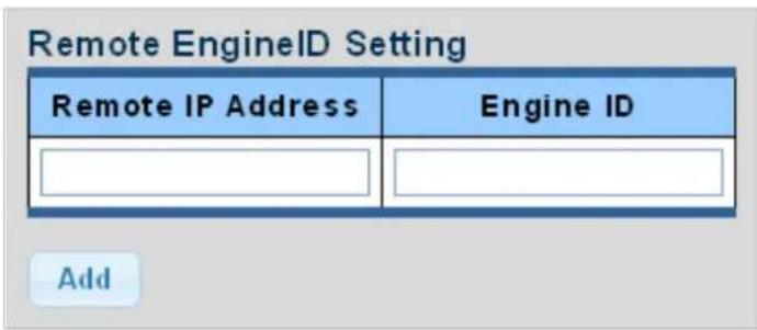
Figure 4-2-37 SNMPv3 Remote Engine ID Setting Screenshot
The page includes the following fields:
| Object Description | |
| • Remote IP Address | Indicates the SNMP remote engine ID address. It allows a valid IP address in dotted decimal notation ('x.y.z.w'). |
| • Engine ID | An octet string identifying the engine ID that this entry should belong to. |
Buttons
Apply
: Click to apply changes.

Figure 4-2-38 SNMPv3 Remote Engine ID Status Screenshot
The page includes the following fields:
| Object Description | |
| • Remote IP Address | Display the current remote IP address |
| • Engine ID | Display the current engine ID |
| • Action | Delete: Delete the remote IP address entry |
4.2.5 RMON
RMON is the most important expansion of the standard SNMP. RMON is a set of MIB definitions, used to define standard network monitor functions and interfaces, enabling the communication between SNMP management terminals and remote monitors. RMON provides a highly efficient method to monitor actions inside the subnets.
MID of RMON consists of 10 groups. The media converter supports the most frequently used group 1, 2, 3 and 9:
■ Statistics: Maintain basic usage and error statistics for each subnet monitored by the Agent.
■ History: Record periodical statistic samples available from Statistics.
- Alarm: Allow management console users to set any count or integer for sample intervals and alert thresholds for RMON Agent records.
■ Event: A list of all events generated by RMON Agent.
Alarm depends on the implementation of Event. Statistics and History display some current or history subnet statistics. Alarm and Event provide a method to monitor any integer data change in the network, and provide some alerts upon abnormal events (sending Trap or record in logs).
4.2.5.1 RMON Statistics
This page provides a Detail of a specific RMON statistics entry; RMON Statistics screen in Figure 4-2-39 appears.
| RMON Counters | Value |
| Drop Events | 0 |
| Octets | 5192377 |
| Packets | 36210 |
| Broadcast Packets | 508 |
| Multicast Packets | 156 |
| CRC / Alignment Errors | 0 |
| Undersize Packets | 0 |
| Oversize Packets | 0 |
| Fragments | 0 |
| Jabbers | 0 |
| Collisions | 0 |
| 64 Bytes Frame | 23107 |
| 65-127 Byte Frames | 5685 |
| 128-255 Byte Frames | 227 |
| 256-511 Byte Frames | 7161 |
| 512-1023 Byte Frames | 30 |
| 1024-1518 Byte Frames | 0 |
Figure 4-2-39: RMON Statistics Detail Screenshot
The page includes the following fields:
| Object Description | |
| • Port | Select port from this drop-down list |
| • Drop Events | The total number of events in which packets were dropped by the probe due to lack of resources |
| • Octets | The total number of octets of data (including those in bad packets) received on the network |
| • Packets | The total number of packets (including bad packets, broadcast packets, and multicast packets) received |
| • Broadcast Packets | The total number of good packets received that were directed to the broadcast address |
| • Multicast Packets | The total number of good packets received that were directed to a multicast address |
| • CRC/Alignment Errors | The total number of packets received that had a length (excluding framing bits, but including FCS octets) of between 64 and 1518 octets |
| • Undersize Packets | The total number of packets received that were less than 64 octets |
| • Oversize Packets | The total number of packets received that were longer than 1518 octets |
| • Fragments | The number of frames which size is less than 64 octets received with invalid CRC |
| • Jabbers | The number of frames which size is larger than 64 octets received with invalid CRC |
| • Collisions | The best estimate of the total number of collisions on this Ethernet segment. |
| • 64 Bytes Frame | The total number of packets (including bad packets) received that were 64 octets in length |
| • 65~127 Byte Frames | The total number of packets (including bad packets) received that were between 65 to 127 octets in length |
| • 128~255 Byte Frames | The total number of packets (including bad packets) received that were between 128 to 255 octets in length |
| • 256~511 Byte Frames | The total number of packets (including bad packets) received that were between 256 to 511 octets in length |
| • 512~1023 Byte Frames | The total number of packets (including bad packets) received that were between 512 to 1023 octets in length |
| • 1024~1518 Byte Frames | The total number of packets (including bad packets) received that were between 1024 to 1518 octets in length |
Buttons
Clear
Click to clear the RMON statistics
4.2.5.2 RMON Event
Configure RMON Event table on this page. The RMON Event screens in Figure 4-2-40 and Figure 4-2-41 appear.
RMON Event
| Select Index | Create New |
| Index | 0 (1-65535) |
| Type | None |
| Community | |
| Owner | (0~31 Characters) |
| Description |
Apply
Figure 4-2-40: RMON Event Configuration Screenshot
The page includes the following fields:
| Object Description | |
| Select Index | Select index from this drop-down list to create new index or modify index |
| Index | Indicates the index of the entry. The range is from 1 to 65535 |
| Type | Indicates the notification of the event, the possible types are:none:The total number of octets received on the interface, including framing characters.log:The number of uni-cast packets delivered to a higher-layer protocol.SNMP-Trap:The number of broad-cast and multi-cast packets delivered to a higher-layer protocol.Log and Trap:The number of inbound packets that are discarded even the packets are normal. |
| Community | Specify the community when trap is sent, the string length is from 0 to 127, default is "public". |
| Owner | Indicates the owner of this event, the string length is from 0 to 127, default is a null string |
| Description | Indicates description of this event, the string length is from 0 to 127, default is a null string |
Buttons
Apply
: Click to apply changes.
| Index | Event Type | Community | Description | Last Sent Time | Owner | Action |
Figure 4-2-41: RMON Event Status Screenshot
The page includes the following fields:
| Object Description | |
| • Index | Display the current event index |
| • Event Type | Display the current event type |
| • Community | Display the current community for SNMP trap |
| • Description | Display the current event description |
| • Last Sent Time | Display the current last sent time |
| • Owner | Display the current event owner |
| • Action | ClickDeleteto delete RMON event entry |
4.2.5.3 RMON Event Log
This page provides an overview of RMON Event Log. The RMON Event Log Table screen in Figure 4-2-42 appears.
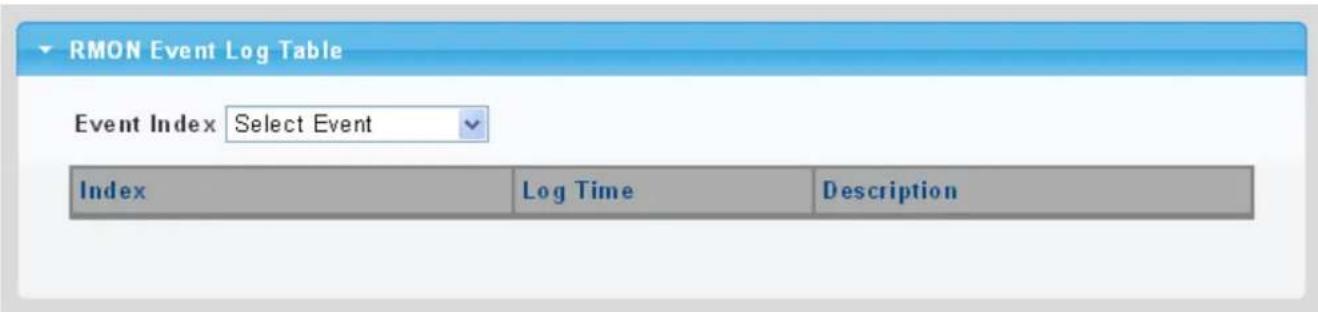
Figure 4-2-42: RMON Event Log Table Screenshot
The page includes the following fields:
| Object Description | |
| • Select Index | Select index from this drop-down list |
| • Index | Indicates the index of the log entry |
| • Log Time | Indicates Event log time |
| • Description | Indicates the Event description |
4.2.5.4 RMON Alarm
Configure RMON Alarm table on this page. The RMON Alarm screens in Figure 4-2-43 and Figure 4-2-44 appear.
RMON Alarm
| Select Index | Create New |
| Index | 0 (1-65535) |
| Sample Port | GE1 |
| Sample Variable | DropEvents |
| Sample Interval | 0 (1-2147483647) |
| Sample Type | ○ absolute ○ delta |
| Rising Threshold | 0 (0-2147483647) |
| Falling Threshold | 0 (0-2147483647) |
| Rising Event | 0: None (Unassigned) |
| Falling Event | 0: None (Unassigned) |
| Owner | (0~31 Characters) |
Apply
Figure 4-2-43: RMON Alarm Table Screenshot
The page includes the following fields:
| Object Description | |
| • Select Index | Select index from this drop-down list to create the new index or modify the index |
| • Index | Indicates the index of the alarm entry |
| • Sample Port | Select port from this drop-down list |
| • Sample Variable | Indicates the particular variable to be sampled, the possible variables are:■ DropEvents: The total number of events in which packets were dropped due to lack of resources.■ Octets: The number of received and transmitted (good and bad) bytes.Includes FCS, but excludes framing bits.■ Pkts: The total number of frames (bad, broadcast and multicast) received and transmitted.■ BroadcastPkts: The total number of good frames received that were directed to the broadcast address. Note that this does not include multicast packets.■ MulticastPkts: The total number of good frames received that were directedto this multicast address.■ CRCAlignErrors: The number of CRC/alignment errors (FCS or alignment errors).■ UnderSizePkts: The total number of frames received that were less than 64 octets long(excluding framing bits, but including FCS octets) and were otherwise well formed.■ OverSizePkts: The total number of frames received that were longer than 1518 octets(excluding framing bits, but including FCS octets) and were otherwise well formed.■ Fragments: The total number of frames received that were less than 64 octets in length (excluding framing bits, but including FCS octets) and had either an FCS or alignment error.■ Jabbers: The total number of frames received that were longer than 1518 octets (excluding framing bits, but including FCS octets), and had either an FCS or alignment error.■ Collisions: The best estimate of the total number of collisions on this Ethernet segment.■ Pkts64Octets: The total number of frames (including bad packets) received and transmitted that were 64 octets in length (excluding framing bits but including FCS octets).■ Pkts64to172Octets: The total number of frames (including bad packets) received and transmitted where the number of octets falls within the specified range (excluding framing bits but including FCS octets).■ Pkts158to255Octets: The total number of frames (including bad packets) received and transmitted where the number of octets falls within the specified range (excluding framing bits but including FCS octets).■ Pkts256to511Octets: The total number of frames (including bad packets) received and transmitted where the number of octets falls within the specified range (excluding framing bits but including FCS octets).■ Pkts512to1023Octets: The total number of frames (including bad packets) received and transmitted where the number of octets falls within the specified range (excluding framing bits but including FCS octets).■ Pkts1024to1518Octets: The total number of frames (including bad packets) received and transmitted where the number of octets falls within the specified range (excluding framing bits but including FCS octets). |
| • Sample Interval | Sample interval (1–2147483647) |
| • Sample Type | The method of sampling the selected variable and calculating the value to be compared against the thresholds, possible sample types are:■ Absolute: Get the sample directly (default).■ Delta: Calculate the difference between samples. |
| • Rising Threshold | Rising threshold value (0–2147483647) |
| • Falling Threshold | Falling threshold value (0–2147483647) |
| • Rising Event | Event to fire when the rising threshold is crossed |
| • Falling Event | Event to fire when the falling threshold is crossed |
| • Owner | Specify an owner for the alarm |
Buttons
Apply
: Click to apply changes.

Figure 4-2-44: RMON Alarm Status Screenshot
The page includes the following fields:
| Object Description | |
| • Index | Indicates the index of Alarm control entry |
| • Sample Port | Display the current sample port |
| • Sample Variable | Display the current sample variable |
| • Sample Interval | Display the current interval |
| • Sample Type | Display the current sample type |
| • Rising Threshold | Display the current rising threshold |
| • Falling Threshold | Display the current falling threshold |
| • Rising Event | Display the current rising event |
| • Falling Event | Display the current falling event |
| • Owner | Display the current owner |
| • Action | ClickDeleteto delete RMON alarm entry |
4.2.5.5 RMON History
Configure RMON History table on this page. The RMON History screens in Figure 4-2-45 and Figure 4-2-46 appear.
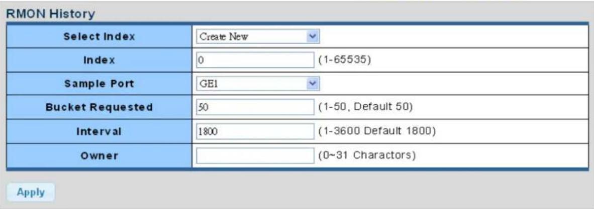
Figure 4-2-45: RMON History Table Screenshot
The page includes the following fields:
| Object Description | |
| Select Index | Select index from this drop-down list to create the new index or modify the index |
| Index | Indicates the index of the history entry |
| Sample Port | Select port from this drop-down list |
| Bucket Requested | Indicates the maximum data entries associated this History control entry stored in RMON. The range is from 1 to 50, default value is 50 |
| Interval | Indicates the interval in seconds for sampling the history statistics data. The range is from 1 to 3600, default value is 1800 seconds. |
| Owner | Specify an owner for the history |
Buttons
Apply
: Click to apply changes.

Figure 4-2-46: RMON History Status Screenshot
The page includes the following fields:
| Object Description | |
| Index | Display the current index |
| Data Source | Display the current data source |
| Bucket Requested | Display the current bucket requested |
| Interval | Display the current interval |
| Owner | Display the current owner |
| Action | Click Delete to delete RMON history entry. |
4.2.5.6 RMON History Log
This page provides a detail of RMON history entries; screen in Figure 4-2-47 appears.
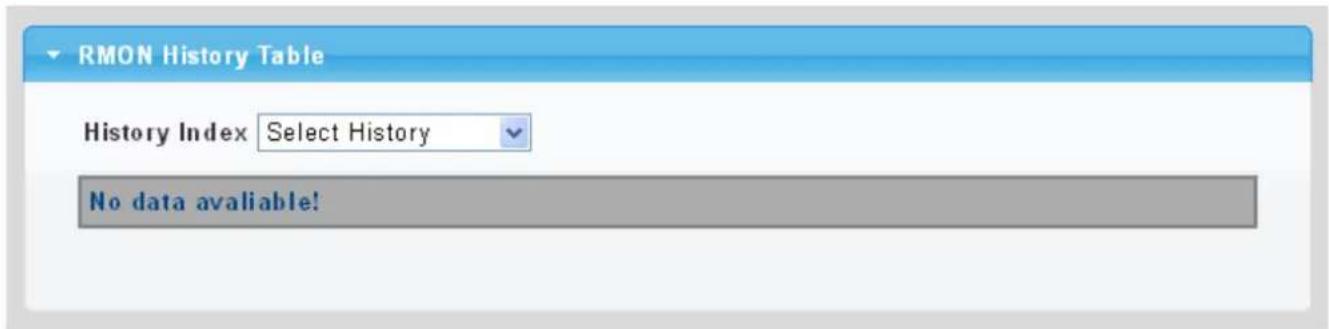
Figure 4-2-47: RMON History Status Screenshot
The page includes the following fields:
| Object Description | |
| • History Index | Select history index from this drop-down list |
Buttons
Apply
: Click to apply changes.
4.2.6 Remote Management
4.2.6.1 Planet NMS Controller
The media converter supports remote management with PLANET NMS controller (sold separately). With enabling this function, it can be monitored by PLANET NMS controller remotely. This page displays remote NMS configuration shown in Figure 4-2-48.
Remote NMS Configuration
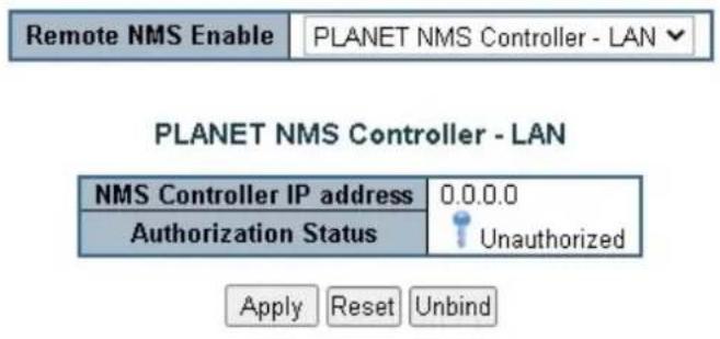
Figure 4-2-48: Remote NMS Configuration page Screenshot
The page includes the following fields:
| Object Description | |
| • Remote NMS Enable | Enable the remote NMS controller management. |
| • NMS Controller IP address | The IP address of remote NMS controller. |
| • Authorization status | Displays the authorization status status for NMS controller, which can be one of the following:■ Unauthorized : The media converter is unauthorized for NMS controller.■ Successful : The media converter is authorized for NMS controller■ Failed : The authorization of NMS controller is failed.■ Disabled : The function of remote NMS management is disabled. |
4.2.6.2 Planet CloudViewer App
PLANET CloudViewer is an intelligent app for monitoring your cloud network. By making data and services available from anywhere with an internet connection, cloud networks offer unprecedented convenience. With PLANET CloudViewer, you can monitor your network status in real-time from your mobile phone or tablet, no matter where you are. You can easily check device information, port status, and PoE status from the cloud, which reduces management costs.
Four Steps to Manage Devices in the Cloud with Ease
The PLANET CloudViewer App enhances user experience by simplifying the cloud connection setup process. It does not require a lot of time to set up, and even non-technical users can do it within minutes.
Step 1: Download: download App from google play or apple store.
Step 2: Register: Create a PLANET CloudViewer account.
Step 3: Bind: Bind network devices to an account.
Step 4: Get: Open App and enjoy the services
Remote NMS Configuration
Remote NMS Configuration
| Remote NMS Enable | PLANET CloudViewer Server - Internet |
| Subscriber email | xx@xx.xx.xx |
| Password | ...... |
| Status | not Enable |
Figure 4-2-49: PLANET CloudViewer App Binding Configuration
After downloading the CloudViewer app on the mobile phone and complete registration, go back to the media converter's web UI and select PLANET CloudViewer Server - Internet in the Remote NMS Configuration page. Enter your account information and apply the setting to bind the media converter to the CloudViewer server. Once the Status shows "success", the media converter is ready to be monitored on your mobile phone.
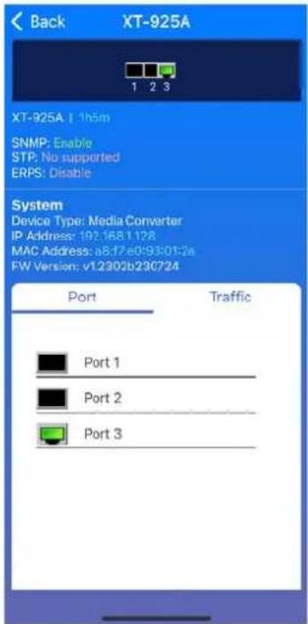
Figure 4-2-50: The screenshot of XT-925A being monitored on a mobile phone
4.3 Switching
Use the Port Menu to display or configure the Managed Media Converter's ports. This section has the following items:
| 4.3.1 Port Management | |
| ☐ Port Configuration | Configures port configuration settings. |
| ☐ Port Counters | Lists Ethernet and RMON port statistics. |
| ☐ Link Fault Passthrough | Link fault detection and propagation |
| ☐ Jumbo Frame | Sets the jumbo frame on the media converter. |
| ☐ Protected Port | Configures protected ports settings. |
| ☐ EEE | Configures EEE settings. |
| ☐ SFP Module Status | Displays SFP module information. |
| ☐ SFP Module Detail Status | Displays SFP module information. |
| 4.3.2 VLAN | |
| ☐ Management VLAN | Configures the management VLAN. |
| ☐ Create VLAN | Creates the VLAN group. |
| ☐ Interface Settings | Configures mode and PVID on the VLAN port. |
| ☐ Port to VLAN | Configures the VLAN membership. |
| ☐ Port VLAN Membership | Display the VLAN membership. |
| 4.3.3 LLDP | |
| ☐ LLDP Global Setting | Configure LLDP global settings on this page. |
| ☐ LLDP Port Setting | Configure LLDP port settings on this page. |
| ☐ LLDP Local Device | Configure LLDP local device settings on this page. |
| ☐ LLDP Remote Device | Configure LLDP remote device settings on this page. |
| ☐ LLDP Statistics | Provide LLDP statistics on this page. |
| 4.3.4 MAC Address Table | |
| ☐ Dynamic Learned | Provide dynamic learned information of whole Ethernetinterfaces on this page. |
| ☐ Dynamic Address Setting | Provide aging time setting on this page. |
| ☐ Static MAC Setting | Provide static MAC address setting on this page. |
| ☐ MAC Filtering | Provide MAC address filtering setting on this page. |
4.3.1 Port Management
4.3.1.1 Port Configuration
This page displays current port configurations and status. Ports can also be configured here. The table has one row for each port on the selected media converter in a number of columns, which are:
The Port Configuration screens in Figure 4-3-1 and Figure 4-3-2 appear.
Port settings
| Port Select | Enabled | Speed | Duplex | Flow Control |
| Select Ports | EnabledDisabled | Auto | Auto | EnabledDisabled |
| Fiber Ports | EnabledDisabled | Auto-1000M | Full | EnabledDisabled |
Apply
Figure 4-3-1 Port Settings Screenshot
The page includes the following fields:
| Object Description | |
| • Port Select | Select port number from this drop-down list. |
| • Enabled | Indicates the port state operation. Possible state are:Enabled- Start up the port manually.Disabled– Shut down the port manually. |
| • Speed | Select any available link speed for the given port. Draw the menu bar to select the mode.Auto- Setup Auto negotiation.Auto-10M- Setup 10M Auto negotiation.Auto-100M- Setup 100M Auto negotiation.Auto-1000M- Setup 1000M Auto negotiation.Auto-10/100M- Setup 10/100M Auto negotiation.10M- Setup 10M Force mode.100M- Setup 100M Force mode.1000M- Setup 1000M Force mode. |
| • Duplex | Select any available link duplex for the given port. Draw the menu bar to select the mode.Auto- Setup Auto negotiation.Full- Force sets Full-Duplex mode.Half- Force sets Half-Duplex mode. |
| • Flow Control | When Auto Speed is selected for a port, this section indicates the flow control capability that is advertised to the link partner. When a fixed-speed setting is selected, that is what is used. Current Rx column indicates whether pause frames on the port are obeyed. Current Tx column indicates whether pause frames on the port are transmitted. The Rx and Tx settings are determined by the result of the last Auto-Negotiation. Check the configured column to use flow control. This setting is related to the setting for Configured Link Speed. |
Buttons
Apply
: Click to apply changes.
Port Status
| Port | Description | Enable State | Link Status | Speed | Duplex | FlowCtrl Config | FlowCtrl Status |
| GE1 | Edit | Enabled | UP | A-1000M | A-Full | Disabled | Disabled |
| GE2 | Edit | Enabled | DOWN | Auto | Auto | Disabled | Disabled |
| GE3 | Edit | Enabled | DOWN | Auto | Auto | Disabled | Disabled |
| GE4 | Edit | Enabled | DOWN | Auto | Auto | Disabled | Disabled |
| GE5 | Edit | Enabled | DOWN | Auto | Auto | Disabled | Disabled |
| GE6 | Edit | Enabled | DOWN | Auto | Auto | Disabled | Disabled |
| GE7 | Edit | Enabled | DOWN | Auto | Auto | Disabled | Disabled |
| GE8 | Edit | Enabled | DOWN | Auto | Auto | Disabled | Disabled |
| GE9 | Edit | Enabled | DOWN | Auto | Auto | Disabled | Disabled |
| GE10 | Edit | Enabled | DOWN | Auto | Auto | Disabled | Disabled |
Figure 4-3-2 Port Status Screenshot
The page includes the following fields:
| Object Description | |
| • Port | This is the logical port number for this row |
| • Description | Click Edit to indicate the port name |
| • Enable State | Display the current port state |
| • Link Status | Display the current link status |
| • Speed | Display the current speed status of the port |
| • Duplex | Display the current duplex status of the port |
| • Flow Control Configuration | Display the current flow control configuration of the port |
| • Flow Control Status | Display the current flow control status of the port |
4.3.1.2 Port Counters
This page provides an overview of traffic and trunk statistics for all ports. The Port Statistics screens in Figure 4-3-3, Figure 4-3-4, Figure 4-3-5 and Figure 4-3-6 appear.
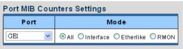
Figure 4-3-3 Port MIB Counters Screenshot
The page includes the following fields:
| Object Description | |
| • Port | Select port number from this drop-down list. |
| • Mode | Select port counters mode.Option:AllInterfaceEther-linkRMON |
| Interface Counters | Counters Value |
| Received Octets | 0 |
| Received Unicast Packets | 0 |
| Received Unknown Unicast Packets | 0 |
| Received Discards Packets | 0 |
| Transmit Octets | 0 |
| Transmit Unicast Packets | 0 |
| Transmit Unknown Unicast Packets | 0 |
| Transmit Discards Packets | 0 |
| Received Multicast Packets | 0 |
| Received Broadcast Packets | 0 |
| Transmit Multicast Packets | 0 |
| Transmit Broadcast Packets | 0 |
| Object | Description |
| Received Octets | The total number of octets received on the interface, including framing characters. |
| Received Unicast Packets | The number of subnetwork-unicast packets delivered to a higher-layer protocol. |
| Received Unknown Unicast Packets | The number of packets received via the interface which is discarded because of an unknown or unsupported protocol. |
| Received Discards Packets | The number of inbound packets which were chosen to be discarded even though no errors had been detected to prevent their being deliverable to a higher-layer protocol. One possible reason for discarding such a packet could be to free up buffer space. |
| Transmit Octets | The total number of octets transmitted out of the interface, including framing characters. |
| Transmit Unicast Packets | The total number of packets that higher-level protocols requested is transmitted to a subnetwork-unicast address, including those that were discarded or not sent. |
| Transmit Unknown Unicast Packets | The total number of packets that higher-level protocols requested is transmitted to a subnetwork-unicast address, including those that were discarded or not sent. |
| Transmit Discards Packets | The number of inbound packets which is chosen to be discarded even though no errors have been detected to prevent from being delivered to a higher-layer protocol. One possible reason for discarding such a packet could be to free up buffer space. |
| Received Multicast Packets | The number of packets, delivered by this sub-layer to a higher (sub-) layer, is addressed to a multicast address at this sub-layer. |
| Received Broadcast Packets | The number of packets, delivered by this sub-layer to a higher (sub-) layer, addressed to a broadcast address at this sub-layer. |
| Transmit Multicast Packets | The total number of packets that higher-level protocols requested is transmitted and is addressed to a multicast address at this sub-layer, including those that were discarded or not sent. |
| Transmit Broadcast Packets | The total number of packets that higher-level protocols requested is transmitted, and addressed to a broadcast address at this sub-layer, including those that were discarded or not sent. |
| Ethernet-link Counters | Counters Value |
| Alignment Errors | 0 |
| FCS Errors | 0 |
| Single Collision Frames | 0 |
| Multiple Collision Frames | 0 |
| Deferred Transmissions | 0 |
| Late Collision | 0 |
| Excessive Collision | 0 |
| Frame Too Longs | 0 |
| Symbol Errors | 0 |
| Control In Unknow Opcodes | 0 |
| In Pause Frames | 0 |
| Out Pause Frames | 0 |
Figure 4-3-4 Interface Counters Screenshot
Figure 4-3-5 Ethernet link Counters Screenshot
| Object Description | |
| • Alignment Errors | The number of alignment errors (missynchronized data packets). |
| • FCS Errors | A count of frames received on a particular interface that are an integral number of octets in length but do not pass the FCS check. This count does not include frames received with frame-too-long or frame-too-short error. |
| • Single Collision Frames | The number of successfully transmitted frames for which transmission is inhibited by exactly one collision. |
| • Multiple Collision Frames | A count of successfully transmitted frames for which transmission is inhibited by more than one collision. |
| • Deferred Transmissions | A count of frames for which the first transmission attempt on a particular interface is delayed because the medium was busy. |
| • Late Collision | The number of times that a collision is detected later than 512 bit-times into the transmission of a packet. |
| • Excessive Collision | A count of frames for which transmission on a particular interface fails due to excessive collisions. This counter does not increase when the interface is operating in full-duplex mode. |
| • Frame Too Long | A count of frames received on a particular interface that exceeds the maximum permitted frame size. |
| • Symbol Errors | The number of received and transmitted symbol errors |
| • Control In Unknown Opcodes | The number of received control unknown opcodes |
| • In Pause Frames | The number of received pause frames |
| • Out Pause Frames | The number of transmitted pause frames |
| RMON Counters | Counters Value |
| Drop Events | 0 |
| Octets | 0 |
| Packets | 0 |
| Broadcast Packets | 0 |
| Multicast Packets | 0 |
| CRC / Alignment Errors | 0 |
| Undersize Packets | 0 |
| Oversize Packets | 0 |
| Fragments | 0 |
| Jabbers | 0 |
| Collisions | 0 |
| 64 Bytes Frame | 0 |
| 65-127 Byte Frames | 0 |
| 128-255 Byte Frames | 0 |
| 256-511 Byte Frames | 0 |
| 512-1023 Byte Frames | 0 |
| 1024-1518 Byte Frames | 0 |
Figure 4-3-6: RMON Counters Screenshot
| Object Description | |
| • Drop Events | The total number of events in which packets were dropped due to lack of resources. |
| • Octets | The total number of octets received and transmitted on the interface, including framing characters. |
| • Packets | The total number of packets received and transmitted on the interface. |
| • Broadcast Packets | The total number of good frames received that were directed to the broadcast address. Note that this does not include multicast packets. |
| • Multicast Packets | The total number of good frames received that were directed to this multicast address. |
| • CRC / Alignment Errors | The number of CRC/alignment errors (FCS or alignment errors). |
| • Undersize Packets | The total number of frames received that were less than 64 octets long(excluding framing bits, but including FCS octets) and were otherwise well formed. |
| • Oversize Packets | The total number of frames received that were longer than 1518 octets(excluding framing bits, but including FCS octets) and were otherwise well formed. |
| • Fragments | The total number of frames received that were less than 64 octets in length (excluding framing bits, but including FCS octets) and had either an FCS or alignment error. |
| • Jabbers | The total number of frames received that were longer than 1518 octets (excluding framing bits, but including FCS octets), and had either an FCS or alignment error. |
| • Collisions | The best estimate of the total number of collisions on this Ethernet segment. |
| • 64 Bytes Frames | The total number of frames (including bad packets) received and transmitted that were 64 octets in length (excluding framing bits but including FCS octets). |
| • 65-127 Byte Frames128-255 Byte Frames256-511 Byte Frames512-1023 Byte Frames1024-1518 ByteFrames | The total number of frames (including bad packets) received and transmitted where the number of octets falls within the specified range (excluding framing bits but including FCS octets). |
4.3.1.3 Link Fault Passthrough
Link Fault Pass-through
Link Fault Pass-through is a networking feature. It facilitates the detection and propagation of link faults or errors from one network device to another. It helps maintain network reliability and minimizes downtime by allowing devices to dynamically respond to link faults. Link Fault Pass-through improves fault detection and enables faster troubleshooting and resolution processes.
How it works:
- When a link fault occurs, the device experiencing the fault generates a notification.
• This notification is then forwarded to other connected devices using Link Fault Pass-through. - Upon receiving the link fault information, the connected devices become aware of the fault.
• This awareness enables them to take appropriate actions, such as rerouting traffic or disabling the affected port.
The LFP group can be made up of Copper-to-Fiber or Fiber-to-Fiber connections. These two types of groupings are shown in Figure 4-3-7 and 4-3-8 respectively.
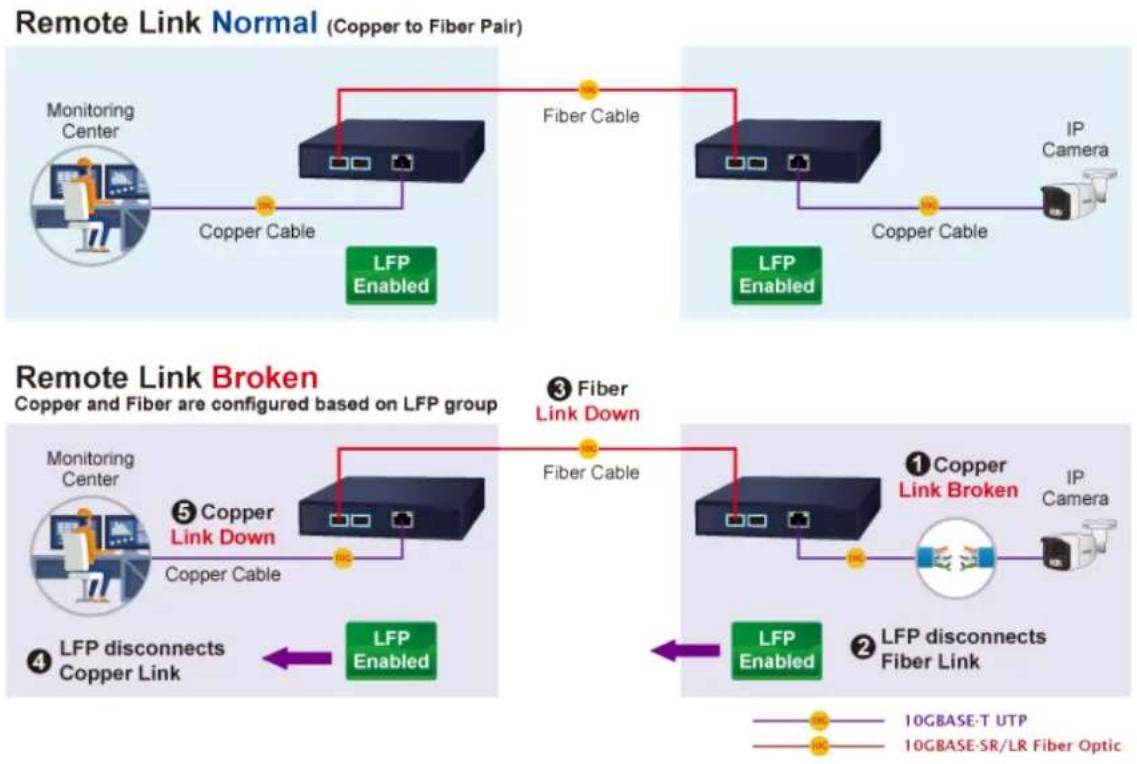
flowchart
graph TD
    subgraph "Remote Link Normal (Copper to Fiber Pair)"
        A["Monitoring Center"] --> B["Copper Cable"]
        B --> C["LFP Enabled"]
        D["Fiber Cable"] --> E["LFP Enabled"]
        F["IP Camera"] --> G["Copper Cable"]
    end

    subgraph "Remote Link Broken
Copper and Fiber are configured based on LFP group"
        H["Monitoring Center"] --> I["Copper Cable"]
        I --> J["LFP Enabled"]
        K["Copper Link Down"] --> L["Fiber Cable"]
        M["IP Camera"] --> N["Copper Link Closed"]
        O["LFP disconnects Copper Link"] --> P["LFP Enabled"]
        Q["LFP disconnects Fiber Link"] --> R["LFP Enabled"]
        S["1 Copper Link Broken"] --> T["IP Camera"]
    end

    style A fill:#f9f,stroke:#333
    style B fill:#f9f,stroke:#333
    style C fill:#f9f,stroke:#333
    style D fill:#f9f,stroke:#333
    style E fill:#f9f,stroke:#333
    style F fill:#f9f,stroke:#333
    style G fill:#f9f,stroke:#333
    style H fill:#f9f,stroke:#333
    style I fill:#f9f,stroke:#333
    style J fill:#f9f,stroke:#333
    style K fill:#f9f,stroke:#333
    style L fill:#f9f,stroke:#333
    style M fill:#f9f,stroke:#333
    style N fill:#f9f,stroke:#333
    style O fill:#f9f,stroke:#333
    style P fill:#f9f,stroke:#333
    style Q fill:#f9f,stroke:#333
    style R fill:#f9f,stroke:#333
Figure 4-3-7: Copper-to-Fiber LFP Group
Remote Link Normal (Fiber to Fiber Pair)
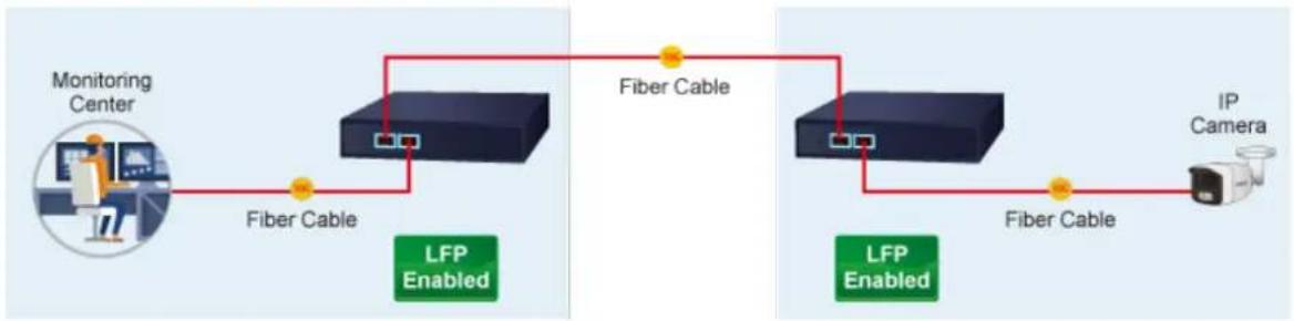
flowchart
graph LR
    A["Monitoring Center"] -->|Fiber Cable| B["LFP Enabled"]
    B -->|Fiber Cable| C["IP Camera"]
    C -->|Fiber Cable| D["LFP Enabled"]
    D -->|Fiber Cable| E["IP Camera"]
Remote Link Broken
Copper and Fiber are configured based on LFP group
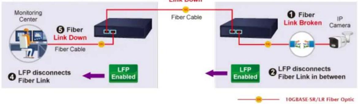
flowchart
graph LR
    A["Monitoring Center"] -->|⑤ Fiber Link Down\nFiber Cable| B["Fiber Cable"]
    B --> C["IP Camera"]
    C --> D["1 Fiber Link Broken"]
    D --> E["LFP Connected Fiber Link in between"]
    E --> F["2 LFP Connected Fiber Link in between"]
    F --> G["4 LFP Disconnects Fiber Link"]
    G --> H["5 LFP Enabled"]
    H --> I["6 LFP Enabled"]
    I --> J["7 LFP Enabled"]
    J --> K["8 LFP Enabled"]
    K --> L["9 LFP Enabled"]
    style A fill:#f9f,stroke:#333
    style B fill:#ccf,stroke:#333
    style C fill:#cfc,stroke:#333
    style D fill:#fcc,stroke:#333
    style E fill:#cff,stroke:#333
    style F fill:#ffc,stroke:#333
    style G fill:#cfc,stroke:#333
    style H fill:#fcc,stroke:#333
    style I fill:#ffc,stroke:#333
    style J fill:#cfc,stroke:#333
    style K fill:#fcc,stroke:#333
Figure 4-3-8: Fiber-to-Fiber LFP Group
Go to the Link Fault Passthrough page to select members for the LFP group and enable LFP mode. The LFP information will then be displayed as shown in Figure 4-3-9.
Link Fault Passthrough Setting
| LFP Group 1 Mode | ○ Disable ● Enable |
Apply
LFP Information
| Group ID | Mode | Fiber Port | Fiber Port | State |
| 1 | Disable | XG1 | XG2 | - |
Figure 4-3-9: Link Fault Passthrough Setting and Information
4.3.1.4 Jumbo Frame
This page provides to select the maximum frame size allowed for the port. The Jumbo Frame screen in Figure 4-3-10 and Figure 4-3-11 appear.

Figure 4-3-10 Jumbo Frame Setting Screenshot
The page includes the following fields:
| Object Description | |
| • Jumbo Frame (Bytes) | Enter the maximum frame size allowed for the port, including FCS. The allowed range is from 64 bytes to 9216 bytes. |
Buttons
Apply
: Click to apply changes.
| Information Name | Information Value |
| Jumbo Frame (Bytes) | 1522 |
Figure 4-3-11 Jumbo Frame Information Screenshot
The page includes the following fields:
| Object Description | |
| • Jumbo | Display the current maximum frame size |
4.3.1.5 Protected Ports
Overview
When a port is configured to be a member of protected group (also called Private VLAN), communication between protected ports within that group can be prevented. Two application examples are provided in this section:
- Customers connected to an ISP can be members of the protected group, but they are not allowed to communicate with each other within that VLAN.
- Servers in a farm of web servers in a Demilitarized Zone (DMZ) are allowed to communicate with the outside world and with database servers on the inside segment, but are not allowed to communicate with each other
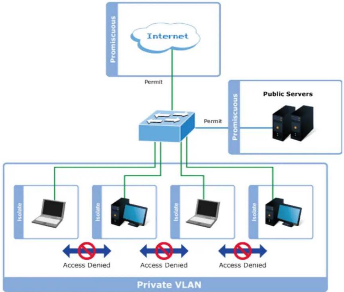
flowchart
graph TD
    A["Internet"] -->|Permit| B["Router"]
    C["Public Servers"] -->|Permit| B
    B --> D["Isolate"]
    B --> E["Isolate"]
    B --> F["Isolate"]
    B --> G["Isolate"]
    D <--> H["Access Denied"]
    E <--> I["Access Denied"]
    F <--> J["Access Denied"]
    G <--> K["Access Denied"]
    L["Private VLAN"] --> M["Isolate"]
    L --> N["Isolate"]
    L --> O["Isolate"]
    L --> P["Isolate"]
For protected port group to be applied, the Managed Media Converter must first be configured for standard VLAN operation.
Ports in a protected port group fall into one of these two groups:
■ Promiscuous (Unprotected) ports
— Ports from which traffic can be forwarded to all ports in the private VLAN
— Ports which can receive traffic from all ports in the private VLAN
■ Isolated (Protected) ports
— Ports from which traffic can only be forwarded to promiscuous ports in the private VLAN
— Ports which can receive traffic from only promiscuous ports in the private VLAN
The configuration of promiscuous and isolated ports applies to all private VLANs. When traffic comes in on a promiscuous port in a private VLAN, the VLAN mask from the VLAN table is applied. When traffic comes in on an isolated port, the private VLAN mask is applied in addition to the VLAN mask from the VLAN table. This reduces the ports to which forwarding can be done to just the promiscuous ports within the private VLAN.
The port settings relate to the currently unit, as reflected by the page header. The Port Isolation Configuration screens in Figure 4-3-12 and Figure 4-3-13 appear.
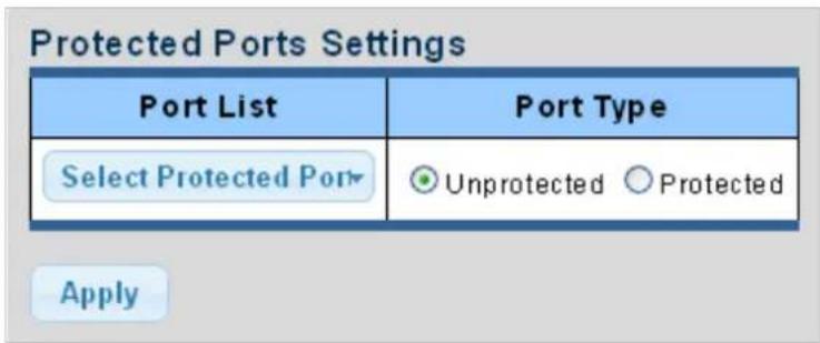
Figure 4-3-12 Protected Ports Settings Screenshot
The page includes the following fields:
| Object Description | |
| Port List | Select port number from this drop-down list. |
| Port Type | Displays protected port types.-Protected:A single stand-alone VLAN that contains one promiscuous port and one or more isolated (or host) ports. This VLAN conveys traffic between the isolated ports and a lone promiscuous port.-Unprotected:A promiscuous port can communicate with all the interfaces within a private VLAN. This is the default setting. |
Buttons
Apply
: Click to apply changes.
| Protected Type | Port List |
| Protected Ports | |
| Unprotected Ports | all |
Figure 4-3-13 Port Isolation Status Screenshot
The page includes the following fields:
| Object Description | |
| Protected Ports | Display the current protected ports |
| Unprotected Ports | Display the current unprotected ports |
4.3.1.6 EEE
What is EEE
EEE is a power saving option that reduces the power usage when there is low or no traffic utilization. EEE works by powering down circuits when there is no traffic. When a port gets data to be transmitted all circuits are powered up. The time it takes to power up the circuits is named wakeup time. The default wakeup time is 17 us for 1Gbit links and 30 us for other link speeds. EEE devices must agree upon the value of the wakeup time in order to make sure that both the receiving and transmitting device has all circuits powered up when traffic is transmitted. The devices can exchange wakeup time information using the LLDP protocol. EEE works for ports in auto-negotiation mode, where the port is negotiated to either 1G or 100 Mbit full duplex mode. For ports that are not EEE-capable the corresponding EEE checkboxes are grayed out and thus impossible to enable EEE for. The EEE port settings relate to the currently unit, as reflected by the page header.
When a port is powered down for saving power, outgoing traffic is stored in a buffer until the port is powered up again. Because there are some overhead in turning the port down and up, more power can be saved if the traffic can be buffered up until a large burst of traffic can be transmitted. Buffering traffic will give some latency in the traffic.
The EEE Port Settings screen in Figure 4-3-14 and Figure 4-3-15 appears.
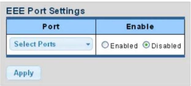
Figure 4-3-14 EEE Port Settings Screenshot
The page includes the following fields:
| Object Description | |
| Port | Select port number from this drop-down list |
| Enable | Enable or disable the EEE function |
Buttons
Apply
: Click to apply changes.
| Port | EEE State |
| XG1 | Disable |
| XG2 | Disable |
| XG3 | Disable |
Figure 4-3-15 EEE Enable Status Screenshot
The page includes the following fields:
| Object Description | |
| Port | The port number of the logical port |
| EEE State | Display the current EEE state |
4.3.1.7 SFP Module Information
Managed Media Converter has supported the SFP module with digital diagnostics monitoring (DDM) function, this feature is also known as digital optical monitoring (DOM). You can check the physical or operational status of an SFP module via the SFP Module Information page. This page shows the operational status, such as the transceiver type, speed, wavelength, optical output power, optical input power, temperature, laser bias current and transceiver supply voltage in real time. You can also use the hyperlink of port no. to check the statistics on a specific interface.
The SFP Module Status screens in Figure 4-3-16 and Figure 4-3-17 appear.
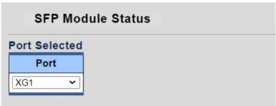
Figure 4-3-16 Port Selected Screenshot
The page includes the following fields:
| Object Description | |
| Port | Select port number from this drop-down list |
Fiber Port Status
| Fiber Status | Status Value |
| OE-Present | Insert |
| LOS | Normal |
| Transceiver Type | SFP/SFP+ |
| Hot Plug | Support |
| Connector Type | COPPER PIGTAIL |
| Ethernet Compliance Code Type | UNKNOWN |
| Transmission Media | UNKNOWN |
| Wave Length | N/S |
| Bitrate | 10300 Mbps |
| Vendor OUI | 00-40-20 |
| Vendor Name | OEM |
| Vendor PN | SFPP-PC10-30X5C |
| Vendor Rev | A0 |
| Vendor SN | GR1404301054 |
| Date Code | 140429 |
| Temperature | N/A |
| Voltage | N/A |
| Current | N/A |
| Output power | N/A |
| Input power | N/A |
Figure 4-3-17 Fiber Port Status Screenshot
The page includes the following fields:
| Object Description | |
| OE-Present | Display the current SFP OE-present |
| LOS | Display the current SFP LOS |
4.3.1.7.2 SFP Module Detail Status
The SFP Module Detail Status screen in Figure 4-3-18 appears.
SFP Module Detail Status
Status Table
| Port | Temperature | Voltage | Current | Output Power | Input Power | Transmitter Fault | Loss of Signal |
| XG1 | N/A | N/A | N/A | N/A | N/A | N/A | N/A |
| XG2 | 18.93 | 3.29 | 0.76 | 0.59 | 0.00 | FALSE | FALSE |
Figure 4-3-18 SFP Module Detail Status Screenshot
The page includes the following fields:
| Object Description | |
| Port | The logical port for the settings contained in the same row |
| Temperature | Display the current SFP temperature |
| Voltage | Display the current SFP voltage |
| Current | Display the current SFP current |
| Output Power | Display the current SFP output power |
| Input Power | Display the current SFP input power |
| Transmit Fault | Display the current SFP transmits fault |
| Loss of Signal | Display the current SFP loss of signal. |
| Rate Ready | Display the current SFP rate ready. |
4.3.2 VLAN
4.3.2.1 VLAN Overview
A Virtual Local Area Network (VLAN) is a network topology configured according to a logical scheme rather than the physical layout. VLAN can be used to combine any collection of LAN segments into an autonomous user group that appears as a single LAN. VLAN also logically segment the network into different broadcast domains so that packets are forwarded only between ports within the VLAN. Typically, a VLAN corresponds to a particular subnet, although not necessarily.
VLAN can enhance performance by conserving bandwidth and improve security by limiting traffic to specific domains.
A VLAN is a collection of end nodes grouped by logic instead of physical location. End nodes that frequently communicate with each other are assigned to the same VLAN, regardless of where they are physically on the network. Logically, a VLAN can be equated to a broadcast domain, because broadcast packets are forwarded to only members of the VLAN on which the broadcast was initiated.
VLAN Overview
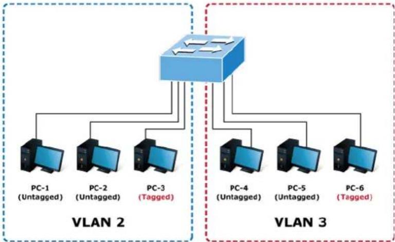
flowchart
graph TD
    subgraph VLAN 2
        PC1["PC-1 (Untagged)"]
        PC2["PC-2 (Untagged)"]
        PC3["PC-3 (Tagged)"]
    end
    subgraph VLAN 3
        PC4["PC-4 (Untagged)"]
        PC5["PC-5 (Untagged)"]
        PC6["PC-6 (Tagged)"]
    end
    PC1 --> PC2
    PC2 --> PC3
    PC3 --> PC4
    PC4 --> PC5
    PC5 --> PC6
    PC3 --> PC4
    PC3 --> PC5
    PC3 --> PC6

- No matter what basis is used to uniquely identify end nodes and assign these nodes VLAN membership, packets cannot cross VLAN without a network device performing a routing function between the VLAN.
- The Managed Media Converter supports IEEE 802.1Q VLAN. The port untagging function can be used to remove the 802.1 tag from packet headers to maintain compatibility with devices that are tag-unaware.

The Managed Media Converter's default is to assign all ports to a single 802.1Q VLAN named DEFAULT_VLAN. As new VLAN is created, the member ports assigned to the new VLAN will be removed from the DEFAULT_VLAN port member list. The DEFAULT_VLAN has a VID = 1.
This section has the following items:
| ■ Management VLAN | Configures the management VLAN |
| ■ Create VLAN | Creates the VLAN group |
| ■ Interface Settings | Configures mode and PVID on the VLAN port |
| ■ Port to VLAN | Configures the VLAN membership |
| ■ Port VLAN Membership | Display the VLAN membership |
4.3.2.2 IEEE 802.1Q VLAN
In large networks, routers are used to isolate broadcast traffic for each subnet into separate domains. This Managed Media Converter provides a similar service at Layer 2 by using VLANs to organize any group of network nodes into separate broadcast domains. VLANs confine broadcast traffic to the originating group and can eliminate broadcast storms in large networks. This also provides a more secure and cleaner network environment.
An IEEE 802.1Q VLAN is a group of ports that can be located anywhere in the network but communicate as though they belong to the same physical segment.
VLANs help to simplify network management by allowing you to move devices to a new VLAN without having to change any physical connections. VLANs can be easily organized to reflect departmental groups (such as Marketing or R&D), usage groups (such as e-mail), or multicast groups (used for multimedia applications such as videoconferencing).
VLANs provide greater network efficiency by reducing broadcast traffic and allow you to make network changes without having to update IP addresses or IP subnets. VLANs inherently provide a high level of network security since traffic must pass through a configured Layer 3 link to reach a different VLAN.
This Managed Media Converter supports the following VLAN features:
■ Up to 255 VLANs based on the IEEE 802.1Q standard.
■ Port overlapping, allowing a port to participate in multiple VLANs.
■ End stations can belong to multiple VLANs.
■ Passing traffic between VLAN-aware and VLAN-unaware devices
IEEE 802.1Q Standard
VLAN allow a network to be segmented in order to reduce the size of broadcast domains. All packets entering a VLAN will only be forwarded to the stations (over IEEE 802.1Q enabled switches) that are members of that VLAN, and this includes broadcast, multicast and unicast packets from unknown sources.
VLAN can also provide a level of security to your network. IEEE 802.1Q VLAN will only deliver packets between stations that are members of the VLAN. Any port can be configured as either tagging or untagging.:
■ The untagging feature of IEEE 802.1Q VLAN allows VLAN to work with legacy switches that don't recognize VLAN tags in packet headers.
■ The tagging feature allows VLAN to span multiple 802.1Q-compliant switches through a single physical connection and allows Spanning Tree to be enabled on all ports and work normally.
Some relevant terms:
- Tagging - The act of putting 802.1Q VLAN information into the header of a packet.
- Untagging - The act of stripping 802.1Q VLAN information out of the packet header.
802.1Q VLAN Tags
The figure below shows the 802.1Q VLAN tag. There are four additional octets inserted after the source MAC address. Their presence is indicated by a value of 0x8100 in the Ether Type field. When a packet's Ether Type field is equal to 0x8100, the packet carries the IEEE 802.1Q/802.1p tag. The tag is contained in the following two octets and consists of 3 bits of user priority, 1 bit of Canonical Format Identifier (CFI - used for encapsulating Token Ring packets so they can be carried across Ethernet backbones), and 12 bits of VLAN ID (VID). The 3 bits of user priority are used by 802.1p. The VID is the VLAN identifier and is used by the 802.1Q standard. Because the VID is 12 bits long, 4094 unique VLAN can be identified.
The tag is inserted into the packet header making the entire packet longer by 4 octets. All of the information originally contained in the packet is retained.
802.1Q Tag
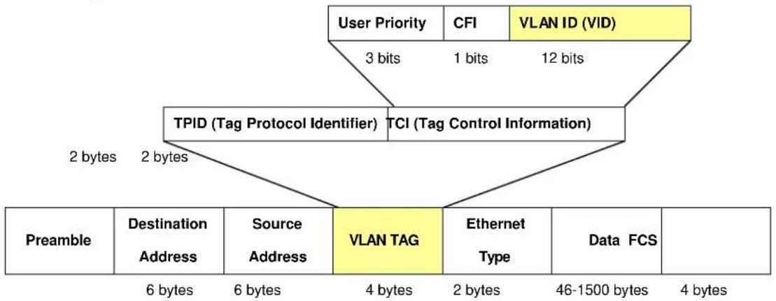
flowchart
graph TD
    A["Preamble"] --> B["Destination Address"]
    B --> C["Source Address"]
    C --> D["VLAN TAG"]
    D --> E["Ethernet Type"]
    E --> F["Data FCS"]
    F --> G["46-1500 bytes"]
    G --> H["2 bytes"]
    H --> I["2 bytes"]
    I --> J["TPID (Tag Protocol Identifier)"]
    J --> K["TCI (Tag Control Information)"]
    K --> L["3 bits"]
    L --> M["CFI"]
    M --> N["VLAN ID (VID)"]
    N --> O["12 bits"]
    O --> P["User Priority"]
The Ether Type and VLAN ID are inserted after the MAC source address, but before the original Ether Type/Length or Logical Link Control. Because the packet is now a bit longer than it was originally, the Cyclic Redundancy Check (CRC) must be recalculated.
Adding an IEEE802.1Q Tag
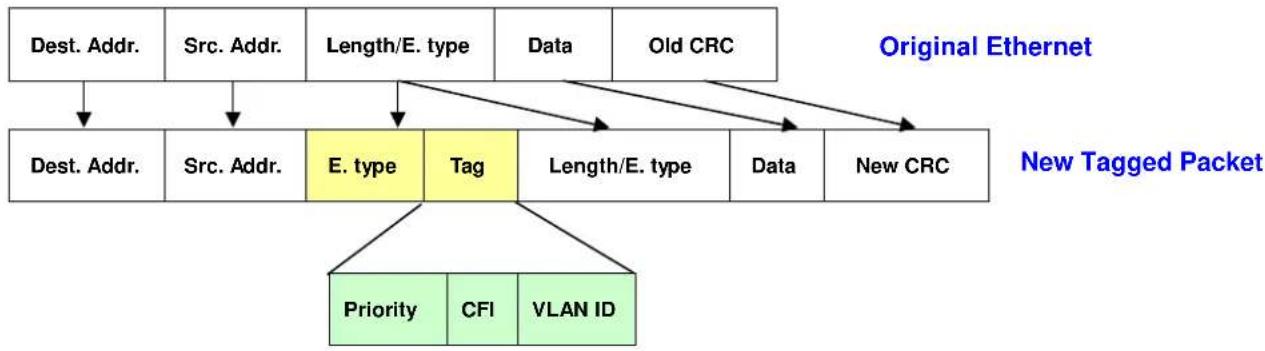
flowchart
graph TD
    A["Dest. Addr."] --> B["Dest. Addr."]
    C["Src. Addr."] --> D["Src. Addr."]
    E["Length/E. type"] --> F["E. type"]
    G["Data"] --> H["Tag"]
    I["Old CRC"] --> J["Length/E. type"]
    K["Data"] --> L["New CRC"]
    M["Priority"] --> N["Priority"]
    O["CFI"] --> P["VLAN ID"]
    Q["Original Ethernet"] --> R["New Tagged Packet"]
Port VLAN ID
Packets that are tagged (are carrying the 802.1Q VID information) can be transmitted from one 802.1Q compliant network device to another with the VLAN information intact. This allows 802.1Q VLAN to span network devices (and indeed, the entire network – if all network devices are 802.1Q compliant).
Every physical port on a switch has a PVID. 802.1Q ports are also assigned a PVID, for use within the switch. If no VLAN are defined on the switch, all ports are then assigned to a default VLAN with a PVID equal to 1. Untagged packets are assigned the PVID of the port on which they were received. Forwarding decisions are based upon this PVID, in so far as VLAN are concerned. Tagged packets are forwarded according to the VID contained within the tag. Tagged packets are also assigned a PVID, but the PVID is not used to make packet forwarding decisions, the VID is.
Tag-aware switches must keep a table to relate PVID within the switch to VID on the network. The switch will compare the VID of a packet to be transmitted to the VID of the port that is to transmit the packet. If the two VID are different the switch will drop the packet. Because of the existence of the PVID for untagged packets and the VID for tagged packets, tag-aware and tag-unaware network devices can coexist on the same network.
A switch port can have only one PVID, but can have as many VID as the switch has memory in its VLAN table to store them.
Because some devices on a network may be tag-unaware, a decision must be made at each port on a tag-aware device before packets are transmitted – should the packet to be transmitted have a tag or not? If the transmitting port is connected to a tag-unaware device, the packet should be untagged. If the transmitting port is connected to a tag-aware device, the packet should be tagged.
Default VLANs
The Switch initially configures one VLAN, VID = 1, called "default." The factory default setting assigns all ports on the Switch to the "default". As new VLAN are configured in Port-based mode, their respective member ports are removed from the "default."
Assigning Ports to VLANs
Before enabling VLANs for the switch, you must first assign each port to the VLAN group(s) in which it will participate. By default all ports are assigned to VLAN 1 as untagged ports. Add a port as a tagged port if you want it to carry traffic for one or more VLANs, and any intermediate network devices or the host at the other end of the connection supports VLANs. Then assign ports on the other VLAN-aware network devices along the path that will carry this traffic to the same VLAN(s), either manually or dynamically using GVRP. However, if you want a port on this switch to participate in one or more VLANs, but none of the intermediate network devices nor the host at the other end of the connection supports VLANs, then you should add this port to the VLAN as an untagged port.

VLAN-tagged frames can pass through VLAN-aware or VLAN-unaware network interconnection devices, but the VLAN tags should be stripped off before passing it on to any end-node host that does not support VLAN tagging.
■ VLAN Classification
When the switch receives a frame, it classifies the frame in one of two ways. If the frame is untagged, the switch assigns the frame to an associated VLAN (based on the default VLAN ID of the receiving port). But if the frame is tagged, the switch uses the tagged VLAN ID to identify the port broadcast domain of the frame.
Port Overlapping
Port overlapping can be used to allow access to commonly shared network resources among different VLAN groups, such as file servers or printers. Note that if you implement VLANs which do not overlap, but still need to communicate, you can connect them by enabled routing on this switch.
■ Untagged VLANs
Untagged (or static) VLANs are typically used to reduce broadcast traffic and to increase security. A group of network users assigned to a VLAN form a broadcast domain that is separate from other VLANs configured on the switch. Packets are forwarded only between ports that are designated for the same VLAN. Untagged VLANs can be used to manually isolate user groups or subnets.
4.3.2.3 Management VLAN
Configure Management VLAN on this page. The screens in Figure 4-3-19 and Figure 4-3-20 appear.

Figure 4-3-19 Management VLAN Setting Screenshot
The page includes the following fields:
| Object Description | |
| • Management VLAN | Provide the managed VLAN ID |
Buttons
Apply
: Click to apply changes.
| Config Name | Config Value |
| Management VLAN | 1 |
Figure 4-3-20 Management VLAN State Screenshot
The page includes the following fields:
| Object Description | |
| • Management VLAN | Display the current management VLAN. |
4.3.2.4 Create VLAN
Create/delete VLAN on this page. The screens in Figure 4-3-21 and Figure 4-3-22 appear.
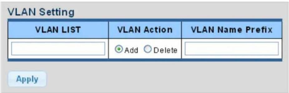
Figure 4-3-21 VLAN Setting Screenshot
The page includes the following fields:
| Object Description | |
| • VLAN List | Indicates the ID of this particular VLAN. |
| • VLAN Action | This column allows users to add or delete VLAN s. |
| • VLAN Name Prefix | Indicates the name of this particular VLAN. |
Buttons
Apply
: Click to apply changes.
| VLAN ID | VLAN Name | VLAN Type | Modify |
| 1 | default | Default | Edit |
Figure 4-3-22 VLAN Table Screenshot
The page includes the following fields:
| Object Description | |
| • VLAN ID | Display the current VLAN ID entry |
| • VLAN Name | Display the current VLAN ID name |
| • VLAN Type | Display the current VLAN ID type |
| • Modify | Click Edit to modify VLAN configuration |
4.3.2.5 Interface Settings
This page is used for configuring the Managed Media Converter port VLAN. The VLAN per Port Configuration page contains fields for managing ports that are part of a VLAN. The port default VLAN ID (PVID) is configured on the VLAN Port Configuration page. All untagged packets arriving to the device are tagged by the ports PVID.
Understand nomenclature of the Switch
IEEE 802.1Q Tagged and Untagged
Every port on an 802.1Q compliant switch can be configured as tagged or untagged.
■ Tagged:
Ports with tagging enabled will put the VID number, priority and other VLAN information into the header of all packets that flow into those ports. If a packet has previously been tagged, the port will not alter the packet, thus keeping the VLAN information intact. The VLAN information in the tag can then be used by other 802.1Q compliant devices on the network to make packet-forwarding decisions.
■ Untagged:
Ports with untagging enabled will strip the 802.1Q tag from all packets that flow into those ports. If the packet doesn't have an 802.1Q VLAN tag, the port will not alter the packet. Thus, all packets received by and forwarded by an untagging port will have no 802.1Q VLAN information. (Remember that the PVID is only used internally within the Switch). Untagging is used to send packets from an 802.1Q-compliant network device to a non-compliant network device.
| Frame IncomeFrame Leave | Income Frame is tagged | Income Frame is untagged |
| Leave port is tagged | Frame remains tagged | Tag is inserted |
| Leave port is untagged | Tag is removed | Frame remain untagged |
Table 4-5-1: Ingress / Egress Port with VLAN VID Tag / Untag Table
IEEE 802.1Q Tunneling (Q-in-Q)
IEEE 802.1Q Tunneling (QinQ) is designed for service providers carrying traffic for multiple customers across their networks.
QinQ tunneling is used to maintain customer-specific VLAN and Layer 2 protocol configurations even when different customers use the same internal VLAN IDs. This is accomplished by inserting Service Provider VLAN (SPVLAN) tags into the customer's frames when they enter the service provider's network, and then stripping the tags when the frames leave the network.
A service provider's customers may have specific requirements for their internal VLAN IDs and number of VLANs supported. VLAN ranges required by different customers in the same service-provider network might easily overlap, and traffic passing through the infrastructure might be mixed. Assigning a unique range of VLAN IDs to each customer would restrict customer configurations, require intensive processing of VLAN mapping tables, and could easily exceed the maximum VLAN limit of 4096.
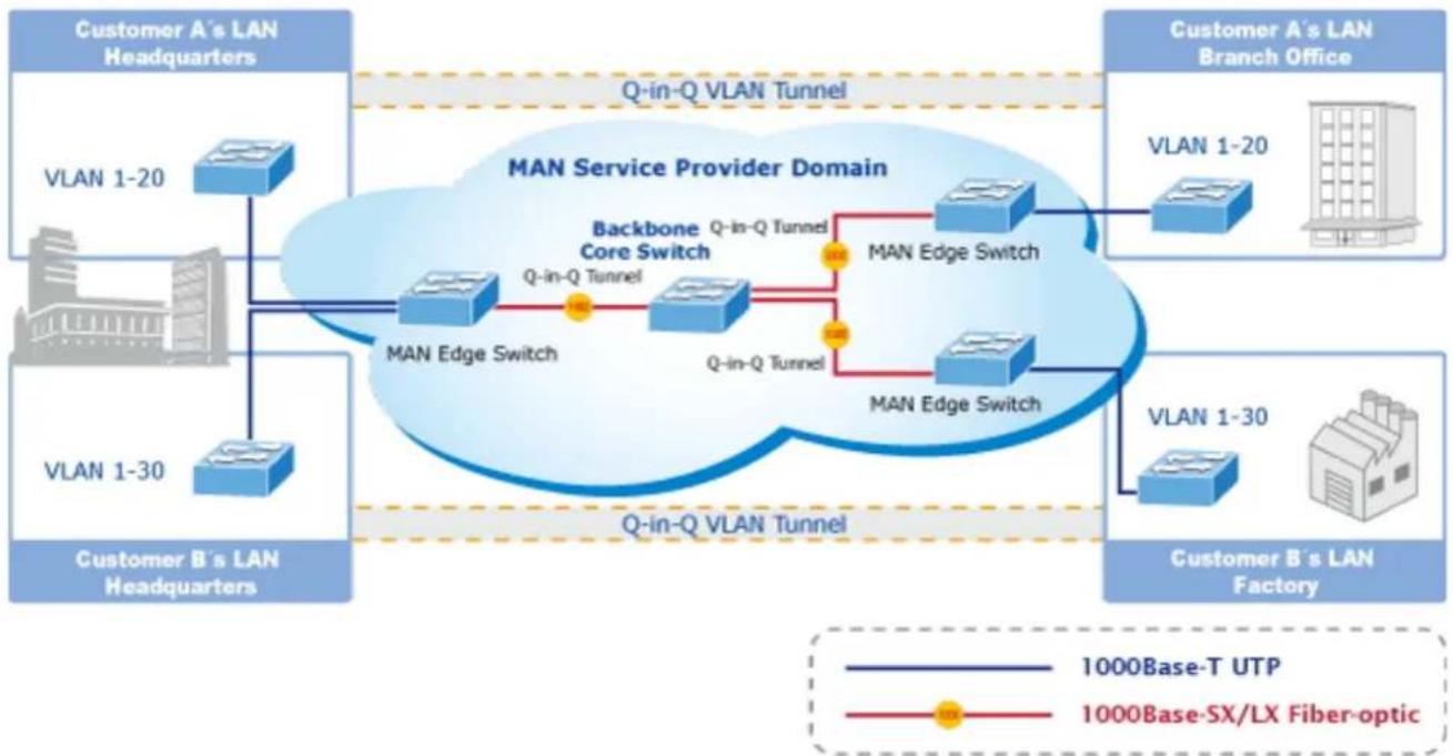
flowchart
graph TD
    subgraph_Customer_A["'Customer A's LAN Headquarters'"]
        A1["VLAN 1-20"] --> B1["MAN Edge Switch"]
        A2["VLAN 1-30"] --> B2["MAN Edge Switch"]
    end

    subgraph_Customer_B["'Customer B's LAN Headquarters'"]
        B2 --> C1["MAN Edge Switch"]
        B3["VLAN 1-30"] --> C2["MAN Edge Switch"]
    end

    subgraph_Customer_B["'Customer B's LAN Factory'"]
        C2 --> D1["MAN Edge Switch"]
        C3["VLAN 1-30"] --> D2["MAN Edge Switch"]
    end

    subgraph_Customer_A["'Customer A's LAN Branch Office'"]
        E1["VLAN 1-20"] --> F1["MAN Edge Switch"]
        E2["VLAN 1-30"] --> F2["MAN Edge Switch"]
    end

    subgraph_Customer_B["'Customer B's LAN Factory'"]
        G1["VLAN 1-30"] --> H1["MAN Edge Switch"]
        G2["VLAN 1-30"] --> H2["MAN Edge Switch"]
    end

    subgraph_Customer_A["'Customer A's LAN Service Provider Domain'"]
        I1["VLAN 1-20"] --> J1["MAN Edge Switch"]
        I2["VLAN 1-30"] --> J2["MAN Edge Switch"]
        I3["VLAN 1-30"] --> J3["MAN Edge Switch"]
    end

    style Customer_A fill:#f9f,stroke:#333
    style Customer_B fill:#f9f,stroke:#333
    style Customer_B fill:#f9f,stroke:#333
    style Customer_B fill:#f9f,stroke:#333
    style Customer_B fill:#f9f,stroke:#333
    style Customer_B fill:#f9f,stroke:#333
    style Customer_B fill:#f9f,stroke:#333
    style Customer_B fill:#f66,stroke:#333
The Managed Media Converter supports multiple VLAN tags and can therefore be used in MAN applications as a provider bridge, aggregating traffic from numerous independent customer LANs into the MAN (Metro Access Network) space. One of the purposes of the provider bridge is to recognize and use VLAN tags so that the VLANs in the MAN space can be used independent of the customers' VLANs. This is accomplished by adding a VLAN tag with a MAN-related VID for frames entering the MAN. When leaving the MAN, the tag is stripped and the original VLAN tag with the customer-related VID is again available.
This provides a tunneling mechanism to connect remote costumer VLANs through a common MAN space without interfering with the VLAN tags. All tags use EtherType 0x8100 or 0x88A8, where 0x8100 is used for customer tags and 0x88A8 are used for service provider tags.
In cases where a given service VLAN only has two member ports on the switch, the learning can be disabled for the particular VLAN and can therefore rely on flooding as the forwarding mechanism between the two ports. This way, the MAC table requirements is reduced.
Edit Interface Setting
The Edit Interface Setting/Status screens in Figure 4-3-23 and Figure 4-3-24 appear.

Figure 4-3-23 Edit Interface Setting Screenshot
The page includes the following fields:
| Object Description | |
| • Port Select | Select port number from this drop-down list to set VLAN port setting. |
| • Interface VLAN Mode | Set the port in access, trunk, hybrid and tunnel mode.■ Trunk means the port allows traffic of multiple VLANs.■ Access indicates the port belongs to one VLAN only.■ Hybrid means the port allows the traffic of multi-VLANs to pass in tag or untag mode.■ Tunnel configures IEEE 802.1Q tunneling for a downlink port to another device within the customer network. |
| • PVID | Allows you to assign PVID to selected port.The PVID will be inserted into all untagged frames entering the ingress port. The PVID must be the same as the VLAN ID that the port belongs to VLAN group, or the untagged traffic will be dropped.The range for the PVID is 1-4094. |
| • Accepted Type | Determines whether the port accepts all frames or only tagged frames. This parameter affects VLAN ingress processing. If the port only accepts tagged frames, untagged frames received on the port are discarded.Options:■ All■ Tag Only■ Untag OnlyBy default, the field is set to All. |
| • Ingress Filtering | If ingress filtering is enabled (checkbox is checked), frames classified to a VLAN that the port is not a member of get discarded.If ingress filtering is disabled, frames classified to a VLAN that the port is not a member of are accepted and forwarded to the switch engine.However, the port will never transmit frames classified to VLANs that it is not a member of. |
| • Uplink | Enable/disable uplink function in trunk port. |
| • TPID | Configure the type (TPID) of the protocol of switch trunk port. |
Button
Apply
: Click to apply changes.
▼ Port VLAN Status
| Port | Interface VLAN Mode | PVID | Accept Frame Type | Ingress Filtering | Uplink | TPID |
| XG1 | Trunk | 1 | ALL | Enable | Disable | 0x8100 |
| XG2 | Trunk | 1 | ALL | Enable | Disable | 0x8100 |
| XG3 | Trunk | 1 | ALL | Enable | Disable | 0x8100 |
Figure 4-3-24 Edit Interface Setting Screenshot
The page includes the following fields:
| Object Description | |
| • Port | The switch port number of the logical port |
| • Interface VLAN Mode | Display the current interface VLAN mode |
| • PVID | Display the current PVID |
| • Accepted Frame Type | Display the current access frame type |
| • Ingress Filtering | Display the current ingress filtering |
| • Uplink | Display the current uplink mode |
| • TPID | Display the current TPID |
4.3.2.6 Port to VLAN
Use the VLAN Static Table to configure port members for the selected VLAN index. This page allows you to add and delete port members of each VLAN. The screen in Figure 4-3-25 appears.
Port to VLAN
▼ Port to VLAN Settings
VLAN ID : 1
| Port | Interface VLAN Mode | Membership | PVID |
| XG1 | Trunk | ○ Forbidden ○ Excluded ○ Tagged ● Untagged | ☑ |
| XG2 | Trunk | ○ Forbidden ○ Excluded ○ Tagged ● Untagged | ☑ |
| XG3 | Trunk | ○ Forbidden ○ Excluded ○ Tagged ● Untagged | ☑ |
Apply
Figure 4-3-25 Port to VLAN Setting Screenshot
The page includes the following fields:
| Object Description | ||
| • VLAN ID | Select VLAN ID from this drop-down list to assign VLAN membership. | |
| • Port | The switch port number of the logical port. | |
| • Interface VLAN Mode | Display the current interface VLAN mode. | |
| • Membership | Select VLAN membership for each interface by marking the appropriate radio button for a port or trunk: | |
| Forbidden: | Interface is forbidden from automatically joining the VLAN via GVRP. | |
| Excluded: | Interface is not a member of the VLAN. Packets associated with this VLAN will not be transmitted by the interface. | |
| Tagged: | Interface is a member of the VLAN. All packets transmitted by the port will be tagged, that is, carry a tag and therefore carry VLAN or CoS information. | |
| Untagged: | Interface is a member of the VLAN. All packets transmitted by the port will be untagged, that is, not carry a tag and therefore not carry VLAN or CoS information. Note that an interface must be assigned to at least one group as an untagged port. | |
| • PVID | Display the current PVID | |
Buttons
Apply
: Click to apply changes.
4.3.2.7 Port VLAN Membership
This page provides an overview of membership status for VLAN users. The VLAN Membership Status screen in Figure 4-3-26 appears.
Port VLAN Membership
▼ Port VLAN Membership Table
| Port | Mode | Administrative VLANs | Operational VLANs | Modify |
| XG1 | Trunk | 1UP | 1P | Edit |
| XG2 | Trunk | 1UP | 1P | Edit |
| XG3 | Trunk | 1UP | 1P | Edit |
Figure 4-3-26 Port VLAN Membership Table Screenshot
The page includes the following fields:
| Object Description | |
| • Port | The switch port number of the logical port |
| • Mode | Display the current VLAN mode |
| • Administrative VLANs | Display the current administrative VLANs |
| • Operational VLANs | Display the current operational VLANs |
| • Modify | Click Edit to modify VLAN membership |
4.3.3 LLDP
4.3.3.1 Link Layer Discovery Protocol
Link Layer Discovery Protocol (LLDP) is used to discover basic information about neighboring devices on the local broadcast domain. LLDP is a Layer 2 protocol that uses periodic broadcasts to advertise information about the sending device. Advertised information is represented in Type Length Value (TLV) format according to the IEEE 802.1ab standard, and can include details such as device identification, capabilities and configuration settings. LLDP also defines how to store and maintain information gathered about the neighboring network nodes it discovers.
Link Layer Discovery Protocol - Media Endpoint Discovery (LLDP-MED) is an extension of LLDP intended for managing endpoint devices such as Voice over IP phones and network switches. The LLDP-MED TLVs advertise information such as network policy, power, inventory, and device location details. LLDP and LLDP-MED information can be used by SNMP applications to simplify troubleshooting, enhance network management, and maintain an accurate network topology.
4.3.3.2 LLDP Global Setting
This page allows the user to inspect and configure the current LLDP port settings. The LLDP Global Setting and Config screens in Figure 4-3-27 and Figure 4-3-28 appear.
Global Settings
| Enabled | Enabled Disabled |
| LLDP PDU Disable Action | Filtering Bridging Flooding |
| Transmission Interval | 30 (5-32768) |
| Holdtime Multiplier | 4 (2-10) |
| Reinitialization Delay | 2 (1-10) |
| Transmit Delay | 2 (1-8192) |
| LLDP-MED Fast Start Repeat Count | 3 (1-10) |
Apply
Figure 4-3-27 Global Setting Screenshot
The page includes the following fields:
| Object Description | |
| Enable | Globally enable or disable LLDP function |
| LLDP PDU Disable Action | Set LLDP PDU disable action: include “Filtering”, “Bridging” and “Flooding”.■ Filtering: discrad all LLDP PDU.■ Bridging: transmit LLDP PDU in the same VLAN.■ Flooding: transmit LLDP PDU for all port. |
| Transmission Interval | The switch is periodically transmitting LLDP frames to its neighbors for having the network discovery information up-to-date. The interval between each LLDP frame is determined by the Transmission Interval value. Valid values are restricted to 5 - 32768 seconds.Default: 30 secondsThis attribute must comply with the following rule:(Transmission Interval * Hold Time Multiplier) ≤65536, and Transmission Interval >= (4 * Delay Interval) |
| Holdtime Multiplier | Each LLDP frame contains information about how long the information in the LLDP frame shall be considered valid. The LLDP information valid period is set to Holdtime multiplied by Transmission Interval seconds. Valid values are restricted to 2 - 10 times.TTL in seconds is based on the following rule:(Transmission Interval * Holdtime Multiplier) ≤ 65536.Therefore, the default TTL is 4*30 = 120 seconds. |
| Reinitialization Delay | When a port is disabled, LLDP is disabled or the switch is rebooted a LLDP shutdown frame is transmitted to the neighboring units, signaling that the LLDP information isn't valid anymore. Tx Reinit controls the amount of seconds between the shutdown frame and a new LLDP initialization. Valid values are restricted to 1 - 10 seconds. |
| Transmit Delay | If some configuration is changed (e.g. the IP address) a new LLDP frame is transmitted, but the time between the LLDP frames will always be at least the value of Transmit Delay seconds. Transmit Delay cannot be larger than 1/4 of the Transmission Interval value. Valid values are restricted to 1 - 8192 seconds.This attribute must comply with the rule:(4 * Delay Interval) ≤Transmission Interval |
| LLDP-MED Fast Start Repeat Count | Configures the amount of LLDP MED Fast Start LLDPDUs to transmit during the activation process of the LLDP-MED Fast Start mechanism.Range: 1-10 packets;Default: 3 packetsThe MED Fast Start Count parameter is part of the timer which ensures that the LLDP-MED Fast Start mechanism is active for the port. LLDP-MED Fast Start is critical to the timely startup of LLDP, and therefore integral to the rapid availability of Emergency Call Service. |
Buttons
Apply
: Click to apply changes.
| Config Name | Config Value |
| LLDP Enabled | Enabled |
| LLDP PDU Disable Action | Flooding |
| Transmission Interval | 30 Secs |
| Holdtme Multiplier | 4 |
| Reinitialization Delay | 2 Secs |
| Transmit Delay | 2 Secs |
| LLDP-MED Fast Start Repeat Count | 3 PDUs |
Figure 4-3-28 LLDP Global Config Screenshot
The page includes the following fields:
| Object Description | |
| LLDP Enable | Display the current LLDP status |
| LLDP PDU Disable Action | Display the current LLDP PDU disable action |
| Transmission Interval | Display the current transmission interval |
| Holdtime Multiplier | Display the current holdtime multiplier |
| Reinitialization Delay | Display the current reinitialization delay |
| Transmit Delay | Display the current transmit delay |
| LLDP-MED Fast Start Repeat Count | Display the current LLDP-MED Fast Start Repeat Count |
4.3.3.3 LLDP Port Setting
Use the LLDP Port Setting to specify the message attributes for individual interfaces, including whether messages are transmitted, received, or both transmitted and received. The LLDP Port Configuration and Status screens in Figure 4-3-29 and Figure 4-3-30 appear.
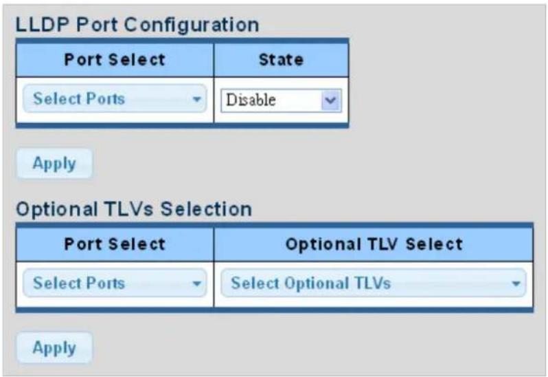
Figure 4-3-29 LLDP Port Configuration and Optional TLVs Selection Screenshot
The page includes the following fields:
| Object Description | |
| • Port Select | Select port from this drop-down list |
| • State | Enables LLDP messages transmit and receive modes for LLDP Protocol Data Units. Options: ■ Tx only ■ Rx only ■ TxRx ■ Disabled |
| • Port Select | Select port from this drop-down list |
| • Optional TLV Select | Configures the information included in the TLV field of advertised messages. ■ System Name: When checked the "System Name" is included in LLDP information transmitted. ■ Port Description: When checked the "Port Description" is included in LLDP information transmitted. ■ System Description: When checked the "System Description" is included in LLDP information transmitted. ■ System Capability: When checked the "System Capability" is included in LLDP information transmitted. ■ 802.3 MAC-PHY: When checked the "802.3 MAC-PHY" is included inLLDP information transmitted.■ 802.3 Link Aggregation: When checked the "802.3 Link Aggregation" is included in LLDP information transmitted.■ 802.3 Maximum Frame Size: When checked the "802.3 Maximum Frame Size" is included in LLDP information transmitted.■ Management Address: When checked the "Management Address" is included in LLDP information transmitted.■ 802.1 PVID: When checked the "802.1 PVID" is included in LLDP information transmitted. |
Buttons
Apply
: Click to apply changes
| Port | State | Selected Optional TLVs |
| XG1 | TX&RX | 802.1 PVID |
| XG2 | TX&RX | 802.1 PVID |
| XG3 | TX&RX | 802.1 PVID |
Figure 4-3-30 LLDP Port Status Screenshot
The page includes the following fields:
| Object Description | |
| • Port | The switch port number of the logical port |
| • State | Display the current LLDP status |
| • Selected Optional TLVs | Display the currently selected optional TLVs |
The VLAN Name TLV VLAN Selection and LLDP Port VLAN TLV Status screens in Figure 4-3-31 and Figure 4-3-32 appear.
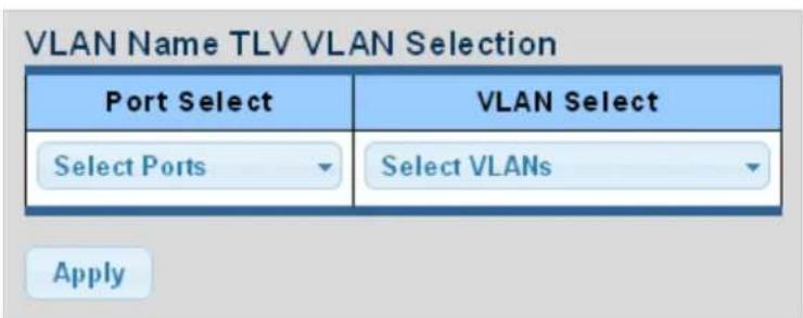
Figure 4-3-31 VLAN Name TLV Selection Screenshot
The page includes the following fields:
| Object Description | |
| • Port Select | Select port from this drop-down list. |
| • VLAN Select | Select VLAN from this drop-down list. |
Buttons
Apply
: Click to apply changes.
| Port | Selected VLAN |
| XG1 | |
| XG2 | |
| XG3 |
Figure 4-3-32 LLDP Port VLAN TLV Status Screenshot
The page includes the following fields:
| Object Description | |
| • Port | The switch port number of the logical port |
| • Selected VLAN | Display the currently selected VLAN |
4.3.3.4 LLDP Local Device
Use the LLDP Local Device Information screen to display information about the switch, such as its MAC address, chassis ID, management IP address, and port information. The Local Device Summary and Port Status screens in Figure 4-3-33 and
Figure 4-3-34 appear.
| Chassis ID Subtype | MAC Address |
| Chassis ID | 00:30:4F:AF:FF:81 |
| System Name | GSD-1002M |
| System Description | V1 |
| Capabilities Supported | Bridge |
| Capabilities Enabled | Bridge |
| Port ID Subtype | Interface name |
Figure 4-3-33 Local Device Summary Screenshot
The page includes the following fields:
| Object Description | |
| • Chassis ID Subtype | Display the current chassis ID subtype |
| • Chassis ID | Display the current chassis ID |
| • System Name | Display the current system name |
| • System Description | Display the current system description |
| • Capabilities Supported | Display the current capabilities supported |
| • Capabilities Enabled | Display the current capabilities enabled |
| • Port ID Subtype | Display the current port ID subtype |
| Port | LLDP Status | |
| XG1 | TX & RX | |
| XG2 | TX & RX | |
| XG3 | TX & RX |
Figure 4-3-34 Port Status Screenshot
The page includes the following fields:
| Object Description | |
| • Interface | The switch port number of the logical port. |
| • LLDP Status | Display the current LLDP status |
| • LLDP MED Status | Display the current LLDP MED Status |
4.3.3.5 LLDP Remove Device
This page provides a status overview for all LLDP remove devices. The displayed table contains a row for each port on which an LLDP neighbor is detected. The LLDP Remove Device screen in Figure 4-3-35 appears.
| LLDP Remote Device | |||||||
| Detail Delete Refresh | |||||||
| Sel | Local Port | Chassis ID Subtype | Chassis ID | Port ID Subtype | Port ID | System Name | Time to Live |
| ☐ | XG1 | MAC address | A8:F7:E0:88:00:30 | Locally assigned | 11 | IGS-5225-8P2S2X | 113 |
Figure 4-3-35 LLDP Remote Device Screenshot
The page includes the following fields:
| Object Description | |
| • Local Port | Display the current local port |
| • Chassis ID Subtype | Display the current chassis ID subtype |
| • Chassis ID | The Chassis ID is the identification of the neighbor's LLDP frames |
| • Port ID Subtype | Display the current port ID subtype |
| • Port ID | The Remote Port ID is the identification of the neighbor port |
| • System Name | System Name is the name advertised by the neighbor unit |
| • Time to Live | Display the current time to live |
Buttons
Delete
: Click to delete LLDP remove device entry.
Refresh
: Click to refresh LLDP remove device.
4.3.3.6 LLDP Statistics
Use the LLDP Device Statistics screen to general statistics for LLDP-capable devices attached to the switch, and for LLDP protocol messages transmitted or received on all local interfaces. The LLDP Global and Port Statistics screens in Figure 4-3-36 and Figure 4-3-37 appear.
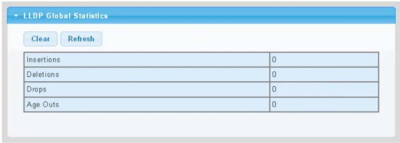
Figure 4-3-36 LLDP Global Statistics Screenshot
The page includes the following fields:
| Object Description | |
| • Insertions | Shows the number of new entries added since switch reboot.\ |
| • Deletions | Shows the number of new entries deleted since switch reboot.\ |
| • Drops | Shows the number of LLDP frames dropped due to that the entry table was full.\ |
| • Age Outs | Shows the number of entries deleted due to Time-To-Live expiring.\ |
Buttons
Clear
Click to clear the statistics
Refresh
: Click to refresh the statistics
LLDP Port Statistics
| Port | TX Frames | RX Frames | RX TLVs | RX Ageouts | |||
| Total | Total | Discarded | Errors | Discarded | Unrecognized | Total | |
| XG1 | 2 | 5 | 0 | 0 | 0 | 0 | 0 |
| XG2 | 0 | 0 | 0 | 0 | 0 | 0 | 0 |
| XG3 | 2 | 0 | 0 | 0 | 0 | 0 | 0 |
Figure 4-3-37 LLDP Port Statistics Screenshot
The page includes the following fields:
| Object Description | |
| • Port | The port on which LLDP frames are received or transmitted |
| • TX Frame – Total | The number of LLDP frames transmitted on the port |
| • RX Frame – Total | The number of LLDP frames received on the port |
| • RX Frame – Discarded | If an LLDP frame is received on a port, and the switch's internal table has run full, the LLDP frame is counted and discarded. This situation is known as "Too Many Neighbors" in the LLDP standard. LLDP frames require a new entry in the table when the Chassis ID or Remote Port ID is not already contained within the table. Entries are removed from the table when a given port links down, an LLDP shutdown frame is received, or when the entry ages out. |
| • RX Frame – Error | The number of received LLDP frames containing some kind of error. |
| • RX TLVs – Discarded | Each LLDP frame can contain multiple pieces of information, known as TLVs (TLV is short for "Type Length Value"). If a TLV is malformed, it is counted and discarded. |
| • RX TLVs – Unrecognized | The number of well-formed TLVs, but with an unknown type value |
| • RX Ageout - Total | The number of organizationally TLVs received |
4.3.4 MAC Address Table
Switching of frames is based upon the DMAC address contained in the frame. The Managed Media Converter builds up a table that maps MAC addresses to switch ports for knowing which ports the frames should go to (based upon the DMAC address in the frame). This table contains both static and dynamic entries. The static entries are configured by the network administrator if the administrator wants to do a fixed mapping between the DMAC address and switch ports.
The frames also contain a MAC address (SMAC address), which shows the MAC address of the equipment sending the frame. The SMAC address is used by the switch to automatically update the MAC table with these dynamic MAC addresses. Dynamic entries are removed from the MAC table if no frame with the corresponding SMAC address has been seen after a configurable age time.
4.3.4.1 Static MAC Setting
The static entries in the MAC table are shown in this table. The MAC table is sorted first by VLAN ID and then by MAC address. The Static MAC Setting screens in Figure 4-3-38 and Figure 4-3-39 appear.
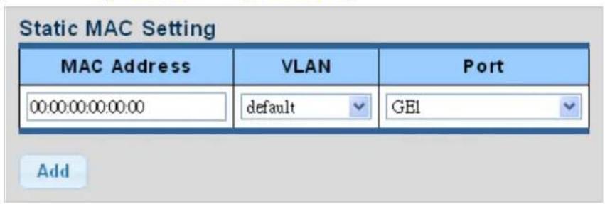
Figure 4-3-38 Statics MAC Setting Screenshot
The page includes the following fields:
| Object Description | |
| • MAC Address | Physical address associated with this interface |
| • VLAN | Select VLAN from this drop-down list |
| • Port | Select port from this drop-down list |
Buttons
Add
: Click to add new static MAC address.
| No. | MAC Address | VLAN | Port | Delete |
| 1 | 00:30 4F AF FF:81 | default(1) | CPU |
Figure 4-3-39 Statics MAC Status Screenshot
The page includes the following fields:
| Object Description | |
| • No. | This is the number for entries |
| • MAC Address | The MAC address for the entry |
| • VLAN | The VLAN ID for the entry |
| • Port | Display the current port |
| • Delete | ClickDeleteto delete static MAC status entry |
4.3.4.2 MAC Filtering
By filtering MAC address, the switch can easily filter the per-configured MAC address and reduce the un-safety. The Static MAC Setting screens in Figure 4-3-40 and Figure 4-3-41 appear.
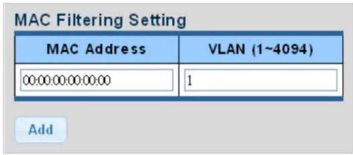
Figure 4-3-40 MAC Filtering Setting Screenshot
The page includes the following fields:
| Object Description | |
| • MAC Address | Physical address associated with this interface |
| • VLAN (1~4096) | Indicates the ID of this particular VLAN |
Buttons
Add
: Click to add new MAC filtering setting.
| No. | MAC Address | VLAN | Action |
Figure 4-3-41 Statics MAC Status Screenshot
The page includes the following fields:
| Object Description | |
| • No. | This is the number for entries |
| • MAC Address | The MAC address for the entry |
| • VLAN | The VLAN ID for the entry |
| • Delete | ClickDeleteto delete static MAC status entry. |
4.3.4.3 Dynamic Address Setting
By default, dynamic entries are removed from the MAC table after 300 seconds. The Dynamic Address Setting/Status screens in Figure 4-3-42 and Figure 4-3-43 appear.
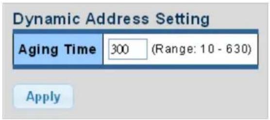
Figure 4-3-42 Dynamic Addresses Setting Screenshot
The page includes the following fields:
| Object Description | |
| • Aging Time | The time after which a learned entry is discardedRange: 10-630 seconds;Default: 300 seconds |
Buttons
Apply
: Click to apply changes.
| Information Name | Information Value |
| Aging time | 300 |
Figure 4-3-43 Dynamic Addresses Status Screenshot
The page includes the following fields:
| Object Description | |
| • Aging Time | Display the current aging time |
4.3.4.4 Dynamic Learned
Dynamic MAC Table
Dynamic Learned MAC Table is shown on this page. The MAC Table is sorted first by VLAN ID and then by MAC address. The Dynamic Learned screens in Figure 4-3-44 and Figure 4-3-45 appear.
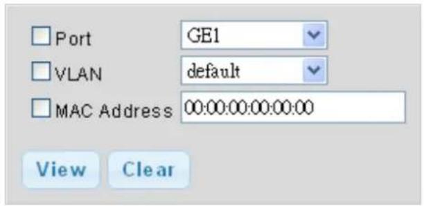
Figure 4-3-44 Dynamic Learned Screenshot
The page includes the following fields:
| Object Description | |
| • Port | Select port from this drop-down list |
| • VLAN | Select VLAN from this drop-down list |
| • MAC Address | Physical address associated with this interface |
Buttons
View
: Refreshes the displayed table starting from the "Start from MAC address" and "VLAN" input fields
Clear
: Flushes all dynamic entries
▼ MAC Address Information
1
| MAC Address | VLAN | Type | Port | |
| 40:61:86:04:18:69 | default(1) | Dynamic | GE1 | Add to Static MAC table |
Total Entries:1
Figure 4-3-45 MAC Address Information Screenshot
| Object Description | |
| • MAC Address | The MAC address of the entry |
| • VLAN | The VLAN ID of the entry |
| • Type | Indicates whether the entry is a static or dynamic entry |
| • Port | The ports that are members of the entry |
Buttons
Add to Static MAC table
: Click to add dynamic MAC address to static MAC address.
4.4 Quality of Service
4.4.1 Understanding QoS
Quality of Service (QoS) is an advanced traffic prioritization feature that allows you to establish control over network traffic. QoS enables you to assign various grades of network service to different types of traffic, such as multi-media, video, protocol-specific, time critical, and file-backup traffic.
QoS reduces bandwidth limitations, delay, loss, and jitter. It also provides increased reliability for delivery of your data and allows you to prioritize certain applications across your network. You can define exactly how you want the switch to treat selected applications and types of traffic.
You can use QoS on your system to:
• Control a wide variety of network traffic by:
• Classifying traffic based on packet attributes.
- Assigning priorities to traffic (for example, to set higher priorities to time-critical or business-critical applications).
- Applying security policy through traffic filtering.
- Provide predictable throughput for multimedia applications such as video conferencing or voice over IP by minimizing delay and jitter.
- Improve performance for specific types of traffic and preserve performance as the amount of traffic grows.
- Reduce the need to constantly add bandwidth to the network.
- Manage network congestion.
To implement QoS on your network, you need to carry out the following actions:
- Define a service level to determine the priority that will be applied to traffic.
- Apply a classifier to determine how the incoming traffic will be classified and thus treated by the Switch.
- Create a QoS profile which associates a service level and a classifier.
- Apply a QoS profile to a port(s).
The QoS page of the Managed Media Converter contains three types of QoS mode - the 802.1p mode, DSCP mode or Port-base mode can be selected. Both the three mode rely on predefined fields within the packet to determine the output queue.
■ 802.1p Tag Priority Mode –The output queue assignment is determined by the IEEE 802.1p VLAN priority tag.
■ IP DSCP Mode - The output queue assignment is determined by the TOS or DSCP field in the IP packets.
■ Port-Base Priority Mode – Any packet received from the specify high priority port will treated as a high priority packet.
The Managed Media Converter supports eight priority level queue, the queue service rate is based on the WRR(Weight Round Robin) and WFQ (Weighted Fair Queuing) algorithm. The WRR ratio of high-priority and low-priority can be set to "4:1 and 8:1.
4.4.2 General
4.4.2.1 QoS Properties
The QoS Global Setting and Information screen in Figure 4-4-1 & Figure 4-4-2 appear.

Figure 4-4-1 QoS Global Setting Screenshot
The page includes the following fields:
| Object Description | |
| • QoS Mode | Enable or disable QoS mode |
Buttons
Apply
: Click to apply changes.
QoS Information
| Information Name | Information Value |
| QoS Mode | disable |
Figure 4-4-2 QoS Information Screenshot
The page includes the following fields:
| Object Description | |
| • QoS Mode | Display the current QoS mode. |
4.4.2.2 QoS Port Settings
The QoS Port Settings and Status screen in Figure 4-4-3 & Figure 4-4-4 appear.
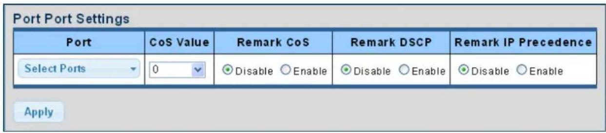
Figure 4-4-3 QoS Port Setting Screenshot
The page includes the following fields:
| Object | Description |
| • Port Select | Select port number for this drop down list. |
| • CoS Value | Select CoS value for this drop down list. |
| • Remark CoS | Disable or enable remark CoS. |
| • Remark DSCP | Disable or enable remark DSCP. |
| • Remark IP Precedence | Disable or enable remark IP Precedence. |
Buttons
Apply
: Click to apply changes.
QoS Port Status
QoS Port Status
| Port | CoS Value | Remark CoS | Remark DSCP | Remark IP Precedence |
| XG1 | 0 | Disable | Disable | Disable |
| XG2 | 0 | Disable | Disable | Disable |
| XG3 | 0 | Disable | Disable | Disable |
Figure 4-4-4 QoS Port Status Screenshot
The page includes the following fields:
| Object Description | |
| • Port | The switch port number of the logical port |
| • CoS Value | Display the current CoS value |
| • Remark CoS | Display the current remark CoS |
| • Remark DSCP | Display the current remark DSCP |
| • Remark IP Precedence | Display the current remark IP precedence |
4.4.2.3 Queue Settings
The Queue Table and Information screens in Figure 4-4-5 & Figure 4-4-6 appear.
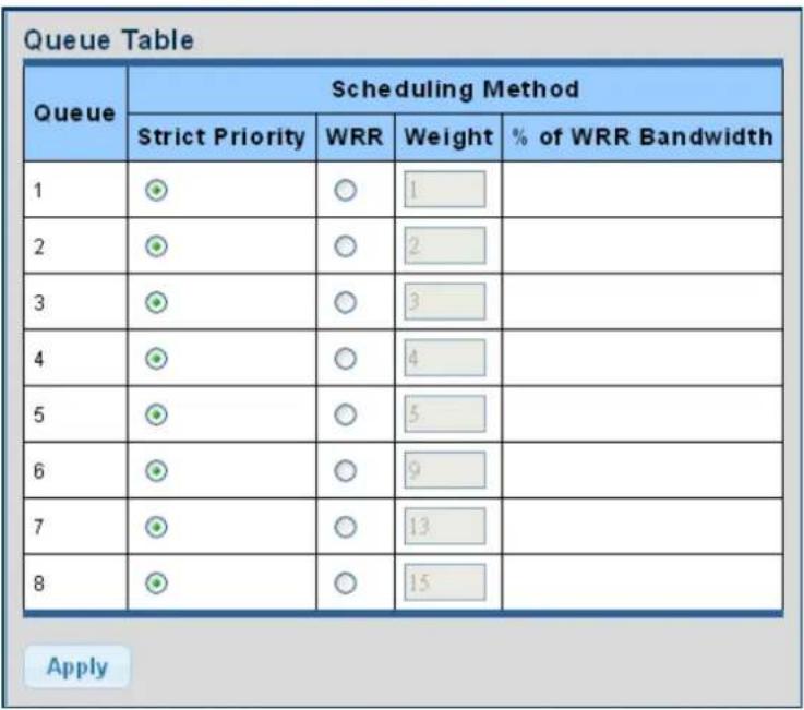
Figure 4-4-5 Queue Table Screenshot
The page includes the following fields:
| Object Description | |
| • Queue | Display the current queue ID |
| • Strict Priority | Controls whether the scheduler mode is "Strict Priority" on this switch port |
| • WRR | Controls whether the scheduler mode is "Weighted" on this switch port |
| • Weight | Controls the weight for this queue. This value is restricted to 1-100. This parameter is only shown if "Scheduler Mode" is set to "Weighted". |
| • % of WRR Bandwidth | Display the current bandwidth for each queue |
Buttons
Apply
: Click to apply changes.
| Information Name | Information Value |
| Strict Priority Queue Number | 8 |
Figure 4-4-6 Queue Information Screenshot
The page includes the following fields:
| Object Description | |
| • Information Name | Display the current queue method information. |
| • Information Value | Display the current queue value information. |
4.4.2.4 CoS Mapping
The CoS to Queue and Queue to CoS Mapping screens in Figure 4-4-7 & Figure 4-4-8 appear.
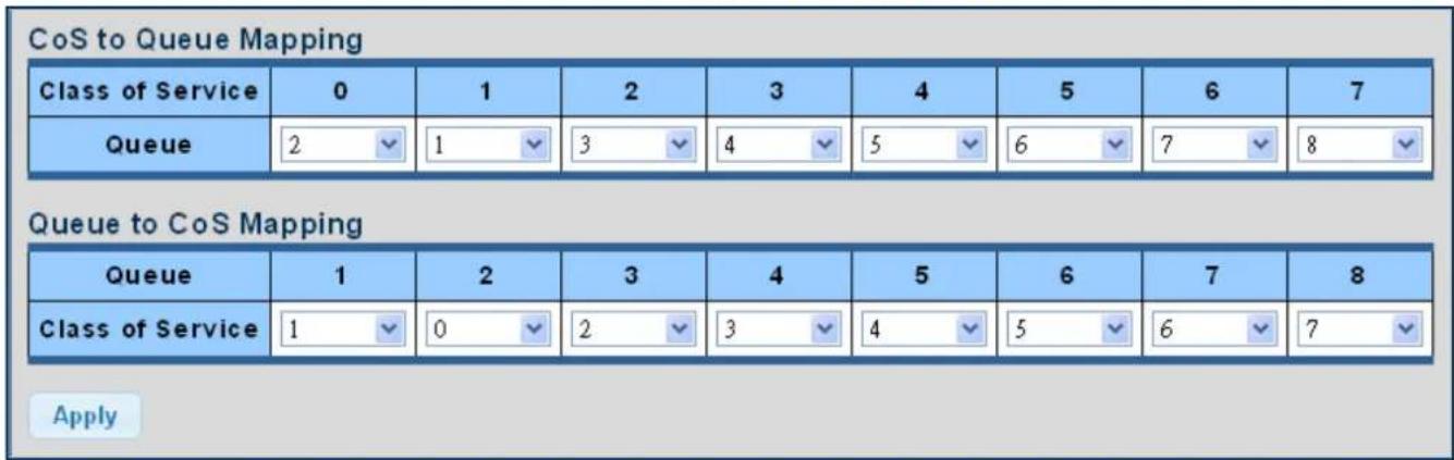
Figure 4-4-7 CoS to Queue and Queue to CoS Mapping Screenshot
The page includes the following fields:
| Object Description | |
| • Queue | Select Queue value for this drop down list. |
| • Class of Service | Select CoS value for this drop down list. |
Buttons
Apply
: Click to apply changes.

CoS Mapping
| CoS | Mapping to Queue |
| 0 | 2 |
| 1 | 1 |
| 2 | 3 |
| 3 | 4 |
| 4 | 5 |
| 5 | 6 |
| 6 | 7 |
| 7 | 8 |
| Queue | Mapping to CoS |
| 1 | 1 |
| 2 | 0 |
| 3 | 2 |
| 4 | 3 |
| 5 | 4 |
| 6 | 5 |
| 7 | 6 |
| 8 | 7 |
Figure 4-4-8 CoS Mapping Screenshot
The page includes the following fields:
| Object Description | |
| • CoS | Display the current CoS value. |
| • Mapping to Queue | Display the current mapping to queue. |
| • Queue | Display the current queue value. |
| • Mapping to CoS | Display the current mapping to CoS. |
4.4.2.5 DSCP Mapping
The DSCP to Queue and Queue to DSCP Mapping screens in Figure 4-4-9 & Figure 4-4-10 appear.
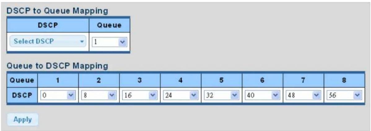
Figure 4-4-9 DSCP to Queue and Queue to DSCP Mapping Screenshot
The page includes the following fields:
| Object Description | |
| • DSCP | Select DSCP value for this dropdown list. |
| • Queue | Select Queue value for this dropdown list. |
Buttons
Apply
: Click to apply changes.
DSCP mapping
| DSCP | Mapping to Queue |
| 0 | 1 |
| 1 | 1 |
| 2 | 1 |
| 3 | 1 |
| 4 | 1 |
| 60 | 8 |
| 61 | 8 |
| 62 | 8 |
| 63 | 8 |
| Queue | Mapping to DSCP |
| 1 | 0 |
| 2 | 8 |
| 3 | 16 |
| 4 | 24 |
| 5 | 32 |
| 6 | 40 |
| 7 | 48 |
| 8 | 56 |
Figure 4-4-10 DSCP Mapping Screenshot
The page includes the following fields:
| Object Description | |
| • DSCP | Display the current CoS value |
| • Mapping to Queue | Display the current mapping to queue |
| • Queue | Display the current queue value |
| • Mapping to DSCP | Display the current mapping to DSCP |
The IP Precedence to Queue and Queue to IP Precedence Mapping screens in Figure 4-4-11 & Figure 4-4-12 appear.
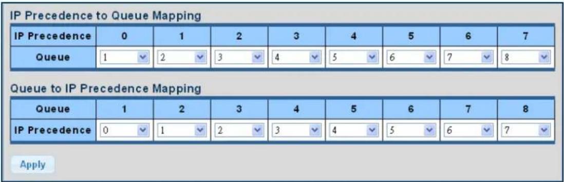
Figure 4-4-11 IP Precedence to Queue and Queue to IP Precedence Mapping Screenshot
The page includes the following fields:
| Object Description | |
| • Queue | Select Queue value for this drop down list |
| • IP Precedence | Select IP Precedence value for this dropdown list |
Buttons
Apply
: Click to apply changes.
| IP Precedence | Mapping to Queue |
| 0 | 1 |
| 1 | 2 |
| 2 | 3 |
| 3 | 4 |
| 4 | 5 |
| 5 | 6 |
| 6 | 7 |
| 7 | 8 |
| Queue | Mapping to IP Precedence |
| 1 | 0 |
| 2 | 1 |
| 3 | 2 |
| 4 | 3 |
| 5 | 4 |
| 6 | 5 |
| 7 | 6 |
| 8 | 7 |
Figure 4-4-12 IP Precedence Mapping Screenshot
The page includes the following fields:
| Object Description | |
| • IP Precedence | Display the current CoS value. |
| • Mapping to Queue | Display the current mapping to queue. |
| • Queue | Display the current queue value. |
| • Mapping to IP Precedence | Display the current mapping to IP Precedence. |
4.4.3 QoS Basic Mode
4.4.3.1 Global Settings
The Basic Mode Global Settings and QoS Information screen in Figure 4-4-13 & Figure 4-4-14 appear.

Figure 4-4-13 Basic Mode Global Settings Screenshot
The page includes the following fields:
| Object Description | |
| • Trust Mode | Set the QoS mode. |
QoS Information
| Information Name | Information Value |
| Trust Mode | COS |
Figure 4-4-14 QoS Information Screenshot
The page includes the following fields:
| Object Description | |
| • Trust Mode | Display the current QoS mode. |
4.4.3.2 Port Settings
The QoS Port Setting and Status screen in Figure 4-4-15 & Figure 4-4-16 appear.
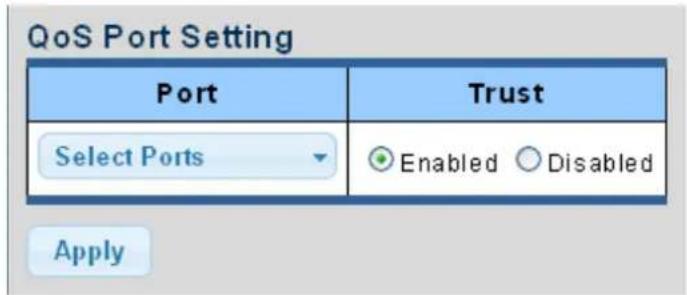
Figure 4-4-15 Basic Mode Global Settings Screenshot
The page includes the following fields:
| Object Description | |
| • Port | Select port number for this drop down list. |
| • Trust Mode | Enable or disable the trust mode. |
Buttons
Apply
: Click to apply changes.
| Port | CoS Value | Remark CoS | Remark DSCP | Remark IP Precedence |
| XG1 | 0 | Disable | Disable | Disable |
| XG2 | 0 | Disable | Disable | Disable |
| XG3 | 0 | Disable | Disable | Disable |
Figure 4-4-16 QoS Port Status Screenshot
The page includes the following fields:
| Object Description | |
| • Port | The switch port number of the logical port. |
| • Trust Mode | Display the current trust type. |
4.4.4 Bandwidth Control
Configure the switch port rate limit for the switch port on this page.
4.4.4.1 Ingress Bandwidth Control
This page provides to select the ingress bandwidth preamble. The Ingress Bandwidth Control Setting and Status screens in Figure 4-4-17 & Figure 4-4-18 appear.
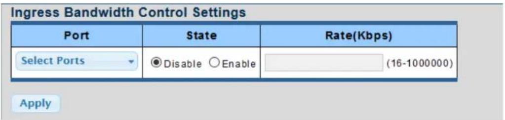
Figure 4-4-17 Ingress Bandwidth Control Settings Screenshot
The page includes the following fields:
| Object Description | |
| • Port | Select port number for this drop down list. |
| • State | Enable or disable the port rate policer. The default value is "Disabled". |
| • Rate (Kbps) | Configure the rate for the port policer. The default value is "unlimited". Valid values are in the range 16 to 1000000. |
Buttons
Apply
: Click to apply changes.
| Port | Ingress RateLimit (Kbps) |
| XG1 | Off |
| XG2 | Off |
| XG3 | Off |
Figure 4-4-18 Ingress Bandwidth Control Status Screenshot
The page includes the following fields:
| Object Description | |
| • Port | The switch port number of the logical port. |
| • Ingress Rate Limit (Kbps) | Display the current ingress rate limit. |
4.4.4.2 Egress Bandwidth Control
This page provides to select the egress bandwidth preamble. The Egress Bandwidth Control Setting and Status screens in Figure 4-4-19 & Figure 4-4-20 appear.
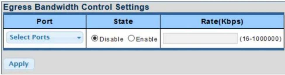
Figure 4-4-19 Egress Bandwidth Control Settings Screenshot
The page includes the following fields:
| Object Description | |
| • Port | Select port number for this drop down list. |
| • State | Enable or disable the port rate policer. The default value is "Disabled". |
| • Rate (Kbps) | Configure the rate for the port policer. The default value is "unlimited". Valid values are in the range 16 to 1000000. |
Buttons
Apply
: Click to apply changes.
Egress Bandwidth Control Status
| Port | Egress RateLimit (Kbps) |
| XG1 | Off |
| XG2 | Off |
| XG3 | Off |
Figure 4-4-20 Egress Bandwidth Control Status Screenshot
The page includes the following fields:
| Object Description | |
| • Port | The switch port number of the logical port. |
| • Egress Rate Limit (Kbps) | Display the current egress rate limit. |
4.4.4.3 Egress Queue
The Egress Queue Bandwidth Control Settings and Status screens in Figure 4-4-21 & Figure 4-4-22 appear.
Egress Queue Bandwidth Control Settings
| Port | Queue | State | CIR(Kbps) |
| GE1 | 1 | Disable Enable | (16-1000000) |
Figure 4-4-21 Egress Queue Bandwidth Settings Screenshot
The page includes the following fields:
| Object Description | |
| • Port | Select port number for this drop down list. |
| • Queue | Select queue number for this drop down list. |
| • State | Enable or disable the port rate policer. The default value is "Disabled". |
| • CIR (Kbps) | Configure the CIR for the port policer. The default value is "unlimited". Valid values are in the range 16 to 1000000. |
Buttons
Apply
: Click to apply changes.
| Queue Id | Rate Limit (Kbps) |
| 1 | off |
| 2 | off |
| 3 | off |
| 4 | off |
| 5 | off |
| 6 | off |
| 7 | off |
| 8 | off |
Figure 4-4-22 Egress Queue Status Screenshot
The page includes the following fields:
| Object Description | |
| • Queue ID | Display the current queue ID. |
| • Rate Limit (Kbps) | Display the current rate limit. |
4.4.5 Storm Control
Storm control for the switch is configured on this Page.
There is an unknown unicast storm rate control, unknown multicast storm rate control, and a broadcast storm rate control.
These only affect flooded frames, i.e. frames with a (VLAN ID, DMAC) pair not present on the MAC Address table.
4.4.5.1 Global Setting
The Storm Control Global Setting and Information screens in Figure 4-4-23 & Figure 4-4-24 appear.
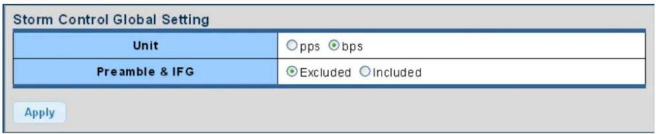
Figure 4-4-23 Storm Control Global Setting Screenshot
The page includes the following fields:
| Object Description | |
| • Unit | Controls the unit of measure for the storm control rate as "pps" or "bps". The default value is "bps". |
| • Preamble & IFG | Set the excluded or included interframe gap |
Buttons
Apply
: Click to apply changes.

Figure 4-4-24 Storm Control Global Information Screenshot
The page includes the following fields:
| Object Description | |
| • Unit | Display the current unit. |
| • Preamble & IFG | Display the current preamble & IFG. |
4.4.5.2 Port Setting
Storm control for the switch is configured on this page. There are three types of storm rate control:
■ Broadcast storm rate control
■ Unknown Multicast storm rate control
■ Unknown Unicast storm rate control
The configuration indicates the permitted packet rate for unknown unicast, unknown multicast, or broadcast traffic across the switch. The Storm Control Configuration screens in Figure 4-4-25 & Figure 4-4-26 appear.
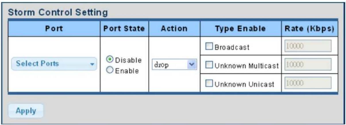
Figure 4-4-25 Storm Control Setting Screenshot
The page includes the following fields:
| Object Description | |
| • Port | Select port for this drop down list. |
| • Port State | Enable or disable the storm control status for the given storm type. |
| • Action | Configures the action performed when storm control is over rate on a port. Valid values are Shutdown or Drop. |
| • Type Enable | The settings in a particular row apply to the frame type listed here: ■ Broadcast ■ Unknown Multicast ■ Unknown Unicast |
| • Rate (kbps/pps) | Configure the rate for the storm control. The default value is "10,000". |
Buttons
Apply
: Click to apply changes
Storm Control Information
| Port | Port State | Broadcast (Kbps) | Unknown Multicast (Kbps) | Unknown Unicast (Kbps) | Action |
| XG1 | Disable | Off (10000) | Off (10000) | Off (10000) | Drop |
| XG2 | Disable | Off (10000) | Off (10000) | Off (10000) | Drop |
| XG3 | Disable | Off (10000) | Off (10000) | Off (10000) | Drop |
Figure 4-4-26 Storm Control Information Screenshot
The page includes the following fields:
| Object Description | |
| • Port | The switch port number of the logical port. |
| • Port State | Display the current port state. |
| • Broadcast (Kbps/pps) | Display the current broadcast storm control rate. |
| • Unknown Multicast (Kbps/pps) | Display the current unknown multicast storm control rate. |
| • Unknown Unicast (Kbps/pps) | Display the current unknown unicast storm control rate. |
| • Action | Display the current action. |
4.5 Security
This section is to control the access of the Managed Media Converter, including the user access and management control.
The Security Page contains links to the following main topics:
■ Access Security
4.5.1 Access Security
This section is to control the access of the Managed Media Converter, including the different access methods – Telnet, SSH, HTTP and HTTPS.
4.5.1.1 Telnet
The Telnet Settings and Information screen in Figure 4-5-1 & Figure 4-5-2 appear.
Telnet Settings
| Telnet Service | Disabled |
| Login Authentication List | default |
| Enable Authentication List | default |
| Session Timeout | 10 (0-65535) minutes |
| Password Retry Count | 3 (0-120) |
| Silent Time | 0 (0-65535) seconds |
Apply
Disconnect
Figure 4-5-1 Telnet Settings Screenshot
The page includes the following fields:
| Object Description | |
| • Telnet Service | Disable or enable telnet service. |
| • Login Authentication List | Select login authentication list for this drop down list. |
| • Enable Authentication List | Select enable authentication list for this drop down list. |
| • Session Timeout | Set the session timeout value. |
| • Password Retry Count | Set the password retry count value. |
| • Silent Time | Set the silent time value. |
Buttons
Apply
: Click to apply changes
Disconnect
: Click to disconnect telnet communication
Telnet Information
| Information Name | Information Value |
| Telnet Service | Disabled |
| Login Authentication List | default |
| Enable Authentication List | default |
| Session Timeout | 10 |
| Password Retry Count | 3 |
| Silent Time | 0 |
| Current Telnet Sessions Count | 0 |
Figure 4-5-2 Telnet Information Screenshot
The page includes the following fields:
| Object Description | |
| • Telnet Service | Display the current Telnet service. |
| • Login Authentication List | Display the current login authentication list. |
| • Enable Authentication List | Display the current enable authentication list. |
| • Session Timeout | Display the current session timeout. |
| • Password Retry Count | Display the current password retry count. |
| • Silent Time | Display the current silent time. |
| • Current Telnet Session Count | Display the current telnet session count |
4.5.1.2 SSH
Configure SSH on this Page. This Page shows the Port Security status. Port Security is a module with no direct configuration. Configuration comes indirectly from other modules - the user modules. When a user module has enabled port security on a port, the port is set-up for software-based learning. In this mode, frames from unknown MAC addresses are passed on to the port security module, which in turn asks all user modules whether to allow this new MAC address to forward or block it. For a MAC address to be set in the forwarding state, all enabled user modules must unanimously agree on allowing the MAC address to forward. If only one chooses to block it, it will be blocked until that user module decides otherwise.
The SSH Settings and Information screens in Figure 4-5-3 & Figure 4-5-4 appear.
SSH Settings
| SSH Service | Disabled |
| Login Authentication List | default |
| Enable Authentication List | default |
| Session Timeout | 10 (0-65535) minutes |
| Password Retry Count | 3 (0-120) minutes |
| Silent Time | 0 (0-65535) seconds |
Apply
Disconnect
Figure 4-5-3 SSH Settings Screenshot
The page includes the following fields:
| Object Description | |
| • SSH Service | Disable or enable SSH service. |
| • Login Authentication List | Select login authentication list for this drop down list. |
| • Enable Authentication List | Select enable authentication list for this drop down list. |
| • Session Timeout | Set the session timeout value. |
| • Password Retry Count | Set the password retry count value. |
| • Silent Time | Set the silent time value. |
Buttons
Apply
: Click to apply changes.
Disconnect
: Click to disconnect telnet communication.
SSH Information
| Information Name | Information Value |
| SSH Service | Disabled |
| Login Authentication List | default |
| Enable Authentication List | default |
| Session Timeout | 10 |
| Password Retry Count | 3 |
| Silent Time | 0 |
| Current SSH Sessions Count | 0 |
Figure 4-5-4 SSH Information Screenshot
The page includes the following fields:
| Object Description | |
| • SSH Service | Display the current SSH service. |
| • Login Authentication List | Display the current login authentication list. |
| • Enable Authentication List | Display the current enable authentication list. |
| • Session Timeout | Display the current session timeout. |
| • Password Retry Count | Display the current password retry count. |
| • Silent Time | Display the current silent time. |
| • Current SSH Session Count | Display the current SSH session count. |
4.5.1.3 HTTP
The HTTP Settings and Information screens in Figure 4-5-5 & Figure 4-5-6 appear.
HTTP Settings
| HTTP Service | Enabled Disabled |
| Login Authentication List | default |
| Session Timeout | 10 (0-86400) minutes |
Apply
Figure 4-5-5 HTTP Settings Screenshot
The page includes the following fields:
| Object Description | |
| • HTTP Service | Disable or enable HTTP service |
| • Login Authentication List | Select login authentication list for this drop down list |
| • Session Timeout | Set the session timeout value |
Buttons
Apply
: Click to apply changes.
| Information Name | Information Value |
| HTTP Service | Enabled |
| Login Authentication List | default |
| Session Timeout | 10 |
Figure 4-5-6 HTTP Information Screenshot
The page includes the following fields:
| Object Description | |
| • HTTP Service | Display the current HTTP service. |
| • Login Authentication List | Display the current login authentication list. |
| • Session Timeout | Display the current session timeout. |
4.5.1.4 HTTPS
The HTTPS Settings and Information screen in Figure 4-5-7 & Figure 4-5-8 appear.
HTTPS Settings
| HTTPS Service | ◎ Enable ○ Disable |
| Automatic Redirect | ◎ Enable ○ Disable |
| Login Authentication List | Default √ |
| Session Timeout | 10 (0-86400) minutes |
Apply
Figure 4-5-7 HTTPS Settings Screenshot
The page includes the following fields:
| Object Description | |
| HTTPS Service | Disable or enable HTTPS service. |
| Automatic Redirect | Disable or enable automatic redirect service. |
| Login Authentication List | Select login authentication list for this drop down list. |
| Session Timeout | Set the session timeout value. |
Buttons
Apply
: Click to apply changes.
HTTPS Information
| Information Name | Information Value |
| HTTPS Service | Enable |
| Automatic Redirect | Enable |
| Login Authentication List | Default |
| Session Timeout | 10 |
Figure 4-5-8 HTTPS Information Screenshot
The page includes the following fields:
| Object Description | |
| HTTPS Service | Display the current HTTPS service. |
| Automatic Redirect | Disable the automatic redirect service. |
| Login Authentication List | Display the current login authentication list. |
| Session Timeout | Display the current session timeout. |
4.5.1.5 Access Method Profile Rules
The Access Method Profile Rules Table Setting and Table screens in Figure 4-5-9 & Figure 4-5-10 appear.
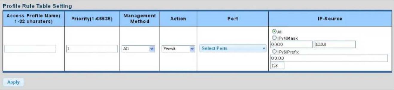
Figure 4-5-9 Profile Rule Table Setting Screenshot
The page includes the following fields:
| Object Description | |
| • Access Profile Name(1-32 characters) | Indicates the access profile name. |
| • Priority (1-65535) | Set priorityThe allowed value is from 1 to 65535 |
| • Management Method | Indicates the host can access the switch from HTTP/HTTPS/telnet/SSH/SNMP/All interface that the host IP address matched the entry. |
| • Action | An IP address can contain any combination of permit or deny rules.(Default: Permit rules)Sets the access mode of the profile; either permit or deny. |
| • Port | Select port for this drop down list |
| • IP-Source | Indicates the IP address for the access management entry |
Buttons
Apply
: Click to apply changes.
| Access Profile Name | Priority | Management Method | Action | Port | Source IPV4 | Source IPV4 Mask | Source IPV6 | Source IPV6 Prefix | Modify |
| default | 1 | All | Permit | gi1-10, Isg1-8 | Edit Delete |
Figure 4-5-10 Profile Rule Table Screenshot
The page includes the following fields:
| Object Description | |
| • Access Profile Name | Display the current access profile name. |
| • Priority | Display the current priority. |
| • Management Method | Display the current management method. |
| • Action | Display the current action. |
| • Port | Display the current port list. |
| • Source IPv4 | Display the current source IPv4 address. |
| • Source IPv4 Mask | Display the current source IPv4 mask. |
| • Source IPv6 | Display the current source IPv6 address. |
| • Source IPv6 Prefix | Display the current source IPv6 prefix. |
| • Modify | Click Edit to edit profile rule parameter.Click Delete to delete profile rule entry. |
4.5.1.6 Access Profiles
The access profile screens in Figure 4-5-11 & Figure 4-5-12 appear.

Figure 4-5-11 Access Profile Screenshot
The page includes the following fields:
| Object Description | |
| • Access Profile | Select access profile for this dropdown list. |
Buttons
Apply
: Click to apply changes.
| Access Profile Name | Delete |
| default | Delete |
Figure 4-5-12 Access Profile Table Screenshot
The page includes the following fields:
| Object Description | |
| • Access Profile | Display the current access profile. |
| • Delete | ClickDeleteto delete access profile entry. |
4.6 Ring
Use the Maintenance menu items to display and configure basic configurations of The Wall-mount Managed Media Converter. Under maintenance, the following topics are provided to back up, upgrade, save and restore the configuration. This section has the following items:
| Ring Wizard | You can quickly build an ERPS ring by wizard. |
| ERPS | You can configure ERPS ring in detail. |
ITU-T G.8032 Ethernet Ring protection switching (ERPS) is a link layer protocol applied on Ethernet loop protection to provide sub-50ms protection and recovery switching for Ethernet traffic in a ring topology. ERPS provides a faster redundant recovery than Spanning Tree topology. The action is similar to STP or RSTP, but the algorithms between them are not the same. In the Ring topology, every switch should be enabled with Ring function and two ports should be assigned as the member ports in the ERPS. Only one switch in the Ring group would be set as the RPL owner switch that one port would be blocked, called owner port, and PRL neighbor switch has one port that one port would be blocked, called neighbor port that connect to owner port directly and this link is called the Ring Protection Link or RPL. Each switch will sends ETH-CCM message to check the link status in the ring group. When the failure of network connection occurs, the nodes block the failed link and report the signal failure message, the RPL owner switch will automatically unblocks the PRL to recover from the failure.
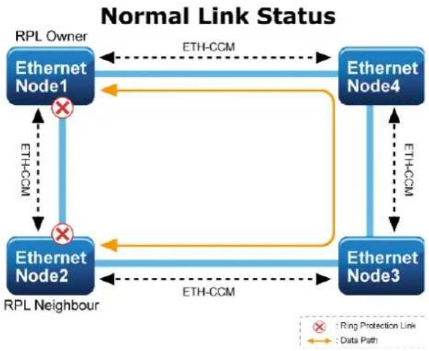
flowchart
graph TD
    A["Ethernet Node1"] -->|ETH-CCM| B["Ethernet Node4"]
    B -->|ETH-CCM| C["Ethernet Node3"]
    C -->|ETH-CCM| D["Ethernet Node2"]
    D -->|RPL Neighbour| A
    A -.->|RPL Owner| A
    B -.->|RPL Owner| B
    C -.->|RPL Owner| C
    D -.->|RPL Owner| D
    style A fill:#666,stroke:#333
    style B fill:#666,stroke:#333
    style C fill:#666,stroke:#333
    style D fill:#666,stroke:#333
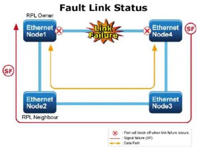
flowchart
graph TD
    A["RPL Owner"] --> B["Ethernet Node1"]
    B --> C["Link Failure"]
    C --> D["Ethernet Node4"]
    D --> E["SF"]
    E --> F["Ethernet Node3"]
    F --> G["Ethernet Node2"]
    G --> H["RPL Neighbour"]
    H --> I["SF"]
    I --> J["RPL Owner"]
    style A fill:#666,stroke:#333
    style B fill:#999,stroke:#333
    style C fill:#ff9,stroke:#333
    style D fill:#999,stroke:#333
    style E fill:#999,stroke:#333
    style F fill:#999,stroke:#333
    style G fill:#999,stroke:#333
    style H fill:#ff9,stroke:#333
    note right of A: *Port will block off when link failure occurs.
    note left of A: *Signal failure (SF)
    note right of H: *Data Path
4.6.1 Ring Wizard
This page allows the user to configure the ERPS by wizard; screen in Figure 4-6-1 appears.
Ring Wizard
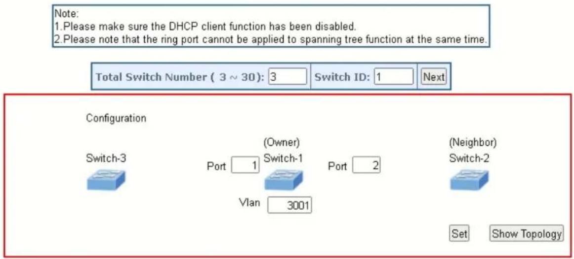
Figure 4-6-1 Ring Wizard page screenshot
The page includes the following fields:
| Object Description | |
| • All Switch Numbers | Set all the switch numbers for the ring group. The default number is 3 and maximum number is 30. |
| • Number ID | The switch where you are requesting ERPS. |
| • Port | Configures the port number for the MEP. |
| • VLAN | Set the ERPS VLAN. |
Buttons

Click to configure ERPS.

: Click to save changes.

Topology: Click to show the ring topology.
4.6.2 ERPS
This page allows the user to inspect and configure the current ERPS Instance; screens in Figure 4-6-2 and Figure 4-6-3 appear.
Ethernet Ring Protection Switching

| Refresh | ||||||||||||
| Delete | Enable | ERPS ID | Version | Ring Type | Port0 | Port1 | Node ID | Control Vlan | Revertive | Guard Time | WTR Time | Holdoff Time |
| ☐ | Yes | 1 | 2 | Major | 5 | 6 | 00:30:4f:1a:12:35 | 3001 | Yes | 500 | 1 | 0 |
Add New Protection Group Apply Reset
Figure 4-6-2 Ethernet Ring Protocol Switch screenshot
| Object | Description |
| Enable | Enables ERPS on the switch. ERPS must be enabled globally on the switch before it can enable on an ERPS ring. |
| ERPS ID | Major ring group ID for the interconnected sub-ring. It is used to send topology change updates on major ring. If ring is major, this value is same as the protection group ID of this ring. |
| Version | ERPS Protocol Version - v1 or v2 |
| Ring Type | Type of Protecting ring. |
| Port 0 | This will create a Port 0 of the switch in the ring. |
| Port 1 | This will create "Port 1" of the switch in the Ring. As interconnected sub-ring will have only one ring port, "Port 1" is configured as "0" for interconnected sub-ring. "0" in this field indicates that no "Port 1" is associated with this instance |
| Node ID | A MAC address unique to the ring node. The MAC address must be specified in the format xx:xx:xx:xx:xx:xx |
| Control Vlan | VLAN configuration of the Protection Group. |
| Revertive | ERPS Protocol Version - v1 or v2 |
| Guard Time | Guard timeout value to be used to prevent ring nodes from receiving outdated R-APS messages.The period of the guard timer can be configured in 10 ms steps between 10 ms and 2 seconds, with a default value of 500 ms |
| WTR Time | Remaining WTR timeout in milliseconds. |
| Holdoff Time | The timing value to be used to make persistent check on Signal Fail before switching.The range of the hold off timer is 0 to 10 seconds in steps of 100 ms |
Buttons
Add New Protection Group
Click to add a new Protection group entry.
Refresh
Click to refresh the page immediately.
Save
Click to save changes.
Reset
: Click to undo any changes made locally and revert to previously saved values.
ERPS Configuration 1
| Enable | ERPS ID | Version | Ring Type | Port0 | Port1 | Node ID | Control VLAN | Revertive | Guard Time | WTR Time | Hold off Time |
| √ | 1 | √2 | Major | 5 | 6 | 00:30:4f:1a:12:35 | 3001 | 500 | 1min | 0 |
Protected VLANs
| VLAN ID | VLAN config |
| 1 | Add/Remove |
RPL Configuration
| RPL Role | RPL Port | Clear |
| RPL_Owner | Port1 |
Instance Command
| Command | Port |
| None | None |
ERPS State
| Protection State | Port 0 | Port 1 | WTR Remaining | RPL Un-blocked | Port 0 Block Status | Port 1 Block Status |
| Protected | OK | SF | 0 | No | Unblocked | Blocked |
Apply Reset
Figure 4-6-3 Ethernet Ring Protocol Switch Configuration page screenshot
RPL Configuration:
| Object Description | |
| • RPL Role | It can be either RPL owner or RPL Neighbor. |
| • RPL Port | This allows to select the east port or west port as the RPL block. |
| • Clear | If the owner has to be changed, then the clear check box allows to clear the RPL owner for that ERPS ring. |
Instance Command:
| Object Description | |
| • Command | Administrative command. A port can be administratively configured to be in either manual switch or forced switch state. |
| • Port | Port selection - Port0 or Port1 of the protection Group on which the command is applied. |
ERPS State:
| Object Description | |
| • Protection State | ERPS state according to State Transition Tables in G.8032. |
| • Port 0 | OK: State of East port is okSF: State of East port is Signal Fail |
| • Port 1 | OK: State of West port is okSF: State of West port is Signal Fail |
| • WTR Remaining | Remaining WTR timeout in milliseconds. |
| • RPL Un-blocked | APS is received on the working flow. |
| • Port 0 Block Status | Block status for Port 0 (Both traffic and R-APS block status). R-APS channel is never blocked on sub-rings without virtual channel. |
| • Port 1 Block Status | Block status for Port 1 (Both traffic and R-APS block status). R-APS channel is never blocked on sub-rings without virtual channel. |
4.7 Maintenance
Use the Maintenance menu items to display and configure basic configurations of the GS-4210 802.3BT PoE++ Series. Under maintenance, the following two topics are provided:
Switch Maintenance
You can save the configuration, reboot or reset default, configuration backup/restore of the switch on this page.
Diagnostics
You can run the cable diagnostics or ping IPv4/IPv6 IP address of the switch on this page.
4.7.1 Switch Maintenance
Under the switch maintenance, the following topics are provided to back up, upgrade, save and restore the configuration. This section has the following items:
| Save Configuration | You can save the configuration of the switch on this page. |
| Factory Default | You can reset default the configuration of the switch on this page. |
| Reboot Switch | You can restart the switch on this page. After restart, the switch will boo normally. |
| Backup Manager | You can back up the switch configuration. |
| Upgrade Manager | You can upgrade the switch configuration. |
| Dual Image | Select active or backup image on this Page. |
4.7.1.1 Save Configuration
You can save the configuration of the switch on this page. The Factory Default screen in Figure 4-7-1 appears.
Save Configuration
| Source File | ◎Running configuration○Startup configuration○Backup configuration |
| Destination File | ◎Startup configuration○Backup configuration |
Apply
Figure 4-7-1 Save Configuration Page Screenshot
Buttons
Apply
: Click to apply changes.
4.7.1.2 Factory Default
You can reset the configuration default of the switch on this page. Only the IP configuration is retained. The new configuration is available immediately, which means that no restart is necessary. The Factory Default screen in Figure 4-7-2 appears and clicks to reset the configuration to Factory Defaults.
Figure 4-7-2 Factory Default Page Screenshot
After the "Restore" button is pressed and rebooted, the system will load the default IP settings as follows:
Default IP address: 192.168.0.100
Subnet mask: 255.255.255.0
Default Gateway: 192.168.0.254
The other setting value is back to disable or none.

To reset the GS-4210 802.3BT PoE++ Series to the factory default setting, you can also press the hardware reset button at the front panel for about 10 seconds. After the device is rebooted, you can log in the management Web interface within the same subnet of 192.168.0.xx.
4.7.1.3 Reboot
The Reboot button enables the device to be rebooted from a remote location. Once the Reboot button is pressed, user has to re-log in the Web interface for about 30 seconds. Click the Reboot button, shown in Figure 4-7-3, to reboot the system.
Figure 4-7-3 Reboot Button
4.7.1.4 Backup Manager
This function allows backup of the current image or configuration of the Managed Media Converter to the local management station. The Backup Manager screen in Figure 4-7-4 appears.
Backup Manager
| Backup Method | TFTP |
| Server IP | (IPv4 or IPv6 Address) |
| Backup Type | ◎ Image○ Running Configuration○ Startup Configuration○ Backup Configuration○ Flash log○ Buffered log |
| Image | ◎ FW-GS-4210-24UP4C_v3.305b230131.bix (Active) ○ FW-GS-4210-24UP4C_v3.305b230131.bix (Backup) |
Backup
Figure 4-7-4 Backup Manager Page Screenshot
The page includes the following fields:
| Object Description | |
| • Backup Method | Select backup method for this drop down list. |
| • Server IP | Fill in your TFTP server IP address. |
| • Backup Type | Select backup type. |
| • Image | Select active or backup image. |
Buttons
Backup
: Click to back up image, configuration or log.
4.7.1.5 Upgrade Manager
This function allows reloading of the current image or configuration of the Managed Media Converter to the local management station. The Upgrade Manager screen in Figure 4-7-5 appears.
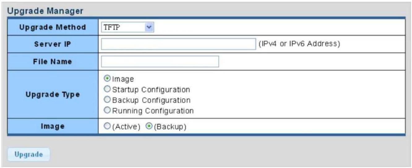
Figure 4-7-5 Upgrade Manager Page Screenshot
The page includes the following fields:
| Object Description | |
| • Upgrade Method | Select upgrade method for this drop down list. |
| • Server IP | Fill in your TFTP server IP address. |
| • File Name | The name of firmware image or configuration. |
| • Upgrade Type | Select upgrade type. |
| • Image | Select active or backup image. |
Buttons
Upgrade
Click to upgrade image or configuration.
4.7.1.6 Dual Image
This page provides information about the active and backup firmware images in the device, and allows you to revert to the backup image. The web page displays two tables with information about the active and backup firmware images. The Dual Image Configuration and Information screens in Figure 4-7-6 & Figure 4-7-7 appear.
Dual Image Configuration
| Active Image | ●FW-GS-4210-24UP4C_v3.305b230131.bix (Active) ○FW-GS-4210- 24UP4C_v3.305b230131.bix (Backup) |
| Apply | |
Figure 4-7-6 Dual Image Configuration Page Screenshot
The page includes the following fields:
| Object Description | |
| • Active Image | Select the active or backup image |
Buttons
Apply
: Click to apply active image.
Images Information
| FW GS 4210.24UP4C_v3.305b230131.bix | Active |
| Flash Partition | 0 |
| Image Name | FW-GS-4210-24UP4C_v3.305b230131.bix |
| Image Size | 6546400 Bytes |
| Created Time | 2023-01-31 11:24:05 UTC |
| FW-GS-4210-24UP4C_v3.305b230131.bix | Backup |
| Flash Partition | 1 |
| Image Name | FW-GS-4210-24UP4C_v3.305b230131.bix |
| Image Size | 6546400 Bytes |
| Created Time | 2023-01-31 11:24:05 UTC |
Figure 4-7-7 Dual Image Information Page Screenshot
The page includes the following fields:
| Object Description | |
| • Flash Partition | Display the current flash partition. |
| • Image Name | Display the current image name. |
| • Image Size | Display the current image size. |
| • Created Time | Display the created time. |
4.7.2 Diagnostics
This section provides the Physical layer and IP layer network diagnostics tools for troubleshooting. The diagnostic tools are designed for network manager to help them quickly diagnose problems to better serve customers.
Use the Diagnostics menu items to display and configure basic administrative details of the GS-4210 802.3BT PoE++ Series. The ping and IPv6 ping allow you to issue ICMP PING packets to troubleshoot IP connectivity issues. The GS-4210 802.3BT PoE++ Series transmits ICMP packets, and the sequence number and roundtrip time are displayed upon reception of a reply. Under System the following topics are provided to configure and view the system information:
This section has the following items:
| ■ Ping Test | You can run the IPv4 IP address ping test of the switch on this page. |
| ■ IPv6 Ping Test | You can run the IPv6 IP address ping test of the switch on this page. |
4.7.2.1 Ping Test
This page allows you to issue ICMP PING packets to troubleshoot IP connectivity issues. After you press "Apply", ICMP packets are transmitted, and the sequence number and roundtrip time are displayed upon reception of a reply. The page refreshes automatically until responses to all packets are received, or until a timeout occurs. The ICMP Ping screen in Figure 4-7-8 appears.
| IP Address | (x.x.x.x or hostname) |
| Count | 4 (1 - 5 | Default : 4 ) |
| Interval (in sec) | 1 (1 - 5 | Default : 1 ) |
| Size (in bytes) | 64 (8 - 5120 | Default : 64 ) |
| Ping Results |
Figure 4-7-8 ICMP Ping Page Screenshot
The page includes the following fields:
| Object Description | |
| • IP Address | The destination IP Address. |
| • Count | Number of echo requests to send. |
| • Interval (in sec) | Send interval for each ICMP packet. |
| • Size (in bytes) | The payload size of the ICMP packet. Values range from 8bytes to 5120bytes. |
| • Ping Results | Display the current ping result. |
Buttons
Apply
Click to transmit ICMP packets.

Be sure the target IP Address is within the same network subnet of the switch, or you have to set up the correct gateway IP address.
4.7.2.2 IPv6 Ping Test
This page allows you to issue ICMPv6 PING packets to troubleshoot IPv6 connectivity issues. After you press "Apply", 5 ICMPv6 packets are transmitted, and the sequence number and roundtrip time are displayed upon reception of a reply. The page refreshes automatically until responses to all packets are received, or until a timeout occurs. The ICMPv6 Ping screen in Figure 4-7-9 appears.
| IPv6 Address | (XX:XX::XX:XX) |
| Count | 4 (1 - 5 | Default : 4 ) |
| Interval (in sec) | 1 (1 - 5 | Default : 1 ) |
| Size (in bytes) | 64 (8 - 5120 | Default : 64 ) |
| Ping Results |
Figure 4-7-9 ICMPv6 Ping Page Screenshot
The page includes the following fields:
| Object Description | |
| • IPv6 Address | The destination IPv6 Address. |
| • Count | Number of echo requests to send. |
| • Interval (in sec) | Send interval for each ICMP packet. |
| • Size (in bytes) | The payload size of the ICMP packet. Values range from 8bytes to 5120bytes. |
| • Ping Results | Display the current ping result. |
Buttons
Apply
: Click to transmit ICMPv6 packets
5. SWITCH OPERATION
5.1 Address Table
The Switch is implemented with an address table. This address table is composed of many entries. Each entry is used to store the address information of some nodes on the network, including MAC address, port no, etc. This information comes from the learning process of Ethernet Switch.
5.2 Learning
When one packet comes in from any port, the Switch will record the source address, port number and the other related information in the address table. This information will be used to decide either forwarding or filtering for future packets.
5.3 Forwarding & Filtering
When one packet comes from some port of the Ethernet Switching, it will also check the destination address besides the source address learning. The Ethernet Switching will look up the address table for the destination address. If not found, this packet will be forwarded to all the other ports except the port, which this packet comes in. And these ports will transmit this packet to the network it connected. If found, and the destination address is located at a different port from this packet comes in, the Ethernet Switching will forward this packet to the port where this destination address is located according to the information from the address table. But, if the destination address is located at the same port with this packet, then this packet will be filtered, thereby increasing the network throughput and availability
5.4 Store-and-Forward
Store-and-Forward is one type of packet-forwarding techniques. A Store-and-Forward Ethernet Switching stores the incoming frame in an internal buffer and does the complete error checking before transmission. Therefore, no error packets occur. It is the best choice when a network needs efficiency and stability.
The Ethernet Switch scans the destination address from the packet-header, searches the routing table provided for the incoming port and forwards the packet, only if required. The fast forwarding makes the switch attractive for connecting servers directly to the network, thereby increasing throughput and availability. However, the switch is most commonly used to segment existence hubs, which nearly always improves the overall performance. An Ethernet Switching can be easily configured in any Ethernet network environment to significantly boost bandwidth using the conventional cabling and adapters.
Due to the learning function of the Ethernet switching, the source address and corresponding port number of each incoming and outgoing packet is stored in a routing table. This information is subsequently used to filter packets whose destination address is on the same segment as the source address. This confines network traffic to its respective domain and reduces the overall load on the network.
The Switch performs "Store and forward"; therefore, no error packets occur. More reliably, it reduces the re-transmission rate. No packet loss will occur.
5.5 Auto-Negotiation
The STP ports on the Switch have a built-in "Auto-negotiation". This technology automatically sets the best possible bandwidth when a connection is established with another network device (usually at Power On or Reset). This is done by detecting the modes and speeds when both devices are connected. Both 10BASE-T and 100BASE-TX devices can connect with the port in either half- or full-duplex mode.
| If attached device is: | 100BASE-TX port will set to: |
| 10Mbps, without auto-negotiation | 10Mbps. |
| 10Mbps, with auto-negotiation | 10/20Mbps (10BASE-T/full-duplex) |
| 100Mbps, without auto-negotiation | 100Mbps |
| 100Mbps, with auto-negotiation | 100/200Mbps (100BASE-TX/full-duplex) |
6. TROUBLESHOOTING
This chapter contains information to help you solve your issue. If the Managed Media Converter is not functioning properly, make sure the Managed Media Converter is set up according to instructions in this manual.
■ The Link LED is not lit
Solution:
Check the cable connection and disable duplex mode of the Managed Media Converter
■ Some stations cannot talk to other stations located on the other port
Solution:
Please check the VLAN settings, trunk settings, and port enabled / disabled status.
■ Performance is not as good as expected
Solution:
Check the duplex status of the Managed Media Converter. If the Managed Media Converter is set to full duplex and its counterpart is set to half duplex, the performance will be poor. Please also check the in/out rate of the port.
Why the media converter doesn't connect to the network
Solution:
- Check the LNK/ACT LED on the Managed Media Converter
- Make sure the cable is connected properly
- Make sure the cable is the right type
- Turn off the power. Wait for a while and turn the power back on.
■ 100BASE-TX port link LED is lit, but the traffic is irregular
Solution:
Check that the attached device is not set to full duplex. Some devices use a physical or software switch to change duplex modes. Auto-negotiation may not recognize this type of full-duplex setting.
■ Media Converter does not power up
Solution:
- Check if the power adapter plug is inserted correctly.
- If the power adapter is well connected, check the AC power.
- User's Manual
- 10Gbps Managed Media Converter
- Trademarks
- Disclaimer
- FCC Warning
- CE Mark Warning
- Energy Saving Note of the Device
- WEEE Warning
- Revision
- Table of Contents
- INTRODUCTION....7
- INSTALLATION....19
- MEDIA CONVERTER MANAGEMENT....28
- WEB CONFIGURATION....36
- INTRODUCTION
- Packet Contents
- Product Description
- Ultra-fast Connections and Secure Management
- 10GBASE-T and 10GBASE-X SFP Dual Media Interfaces for Diversified Bandwidth Applications
- Two Fiber Optic Ports Double the Distance of Deployment (Apply to XT-915A and XT-925A)
- Link Fault Pass-through
- How it works:
- Network with Cybersecurity Helps Minimize Risks
- Redundant Ring, Fast Recovery for Critical Network Applications
- IPv6/IPv4 Dual Stack Management
- SNMP for Comprehensive Network Monitoring and Centralized Control
- Layer 2 Features
- Efficient Traffic Control
- Intelligent SFP Diagnosis Mechanism
- Remote Management Solution
- How to Use This Manual
- Product Features
- Physical Port
- Quality of Service
- Management
- Security
- Case and Installation
- INSTALLATION
- Hardware Description
- Physical Dimensions
- Front Panel
- 10G TP Interface
- SFP+ Slot
- ■ Reset Button
- LED Indications
- LED Definition:
- Installing the Industrial Media Converter
- Installation Steps
- Wall Mount Plate Mounting
- Cabling
- ■ 100/1000/2500/5000/10000BASE-T
- ■ 100/1000/2500/10000BASE-X
- ■ Cabling
- Installing the SFP Transceiver
- ■ Approved PLANET SFP/SFP+ Transceivers
- - Connect the fiber cable
- Removing the SFP/SFP+ Transceiver
- MEDIA CONVERTER MANAGEMENT
- This chapter covers the following topics:
- Requirements
- Management Access Overview
- CLI Mode Management
- Remote SSH Login
- Configuring IP Address
- ■ Display of the Current IP Address
- ■ Configuration of the IP Address
- Storing the Current Switch Configuration
- Web Management
- SNMP-based Network Management
- PLANET Smart Discovery Utility
- About Web-based Management
- ■ Logging on the media converter
- Main Web Page
- Panel Display
- Main Menu
- Buttons
- Save Button
- Configuration Manager
- Saving Configuration
- System
- Management
- System Information
- Edit
- IP Configurations
- Apply
- IP Information
- IPv6 Configuration
- User Configuration
- Time Settings
- System Time
- System Time Informations
- SNTP Server Settings
- Log Management
- Logging Service
- Local Logging
- Remote Syslog
- Logging Message
- View
- Logging Information
- Logging Messages
- Clear
- Refresh
- SNMP Management
- SNMP Overview
- SNMP Operations
- SNMP community
- SNMP Setting
- SNMP Community
- SNMP View
- SNMP Access Group
- Add
- Delete
- SNMP User
- SNMPv1, 2 Notification Recipients
- SNMPv3 Notification Recipients
- SNMP Engine ID
- SNMP Remote Engine ID
- RMON
- RMON Statistics
- RMON Event
- RMON Event Log
- RMON Alarm
- RMON History
- RMON History Log
- Remote Management
- Planet NMS Controller
- Planet CloudViewer App
- Four Steps to Manage Devices in the Cloud with Ease
- Remote NMS Configuration
- Switching
- Port Management
- Port Configuration
- Port Counters
- Link Fault Passthrough
- Jumbo Frame
- Protected Ports
- Overview
- ■ Promiscuous (Unprotected) ports
- ■ Isolated (Protected) ports
- EEE
- What is EEE
- SFP Module Information
- Fiber Port Status
- SFP Module Detail Status
- SFP Module Detail Status
- VLAN
- VLAN Overview
- IEEE 802.1Q VLAN
- IEEE 802.1Q Standard
- Some relevant terms:
- 802.1Q VLAN Tags
- Port VLAN ID
- Default VLANs
- Assigning Ports to VLANs
- ■ VLAN Classification
- Port Overlapping
- ■ Untagged VLANs
- Management VLAN
- Create VLAN
- Interface Settings
- Understand nomenclature of the Switch
- IEEE 802.1Q Tagged and Untagged
- ■ Tagged:
- ■ Untagged:
- IEEE 802.1Q Tunneling (Q-in-Q)
- Edit Interface Setting
- Button
- ▼ Port VLAN Status
- Port to VLAN
- Port to VLAN
- ▼ Port to VLAN Settings
- Port VLAN Membership
- Port VLAN Membership
- ▼ Port VLAN Membership Table
- LLDP
- Link Layer Discovery Protocol
- LLDP Global Setting
- LLDP Port Setting
- LLDP Local Device
- LLDP Remove Device
- LLDP Statistics
- LLDP Port Statistics
- MAC Address Table
- Static MAC Setting
- MAC Filtering
- Dynamic Address Setting
- Dynamic Learned
- Dynamic MAC Table
- ▼ MAC Address Information
- Add to Static MAC table
- Quality of Service
- Understanding QoS
- General
- QoS Properties
- QoS Information
- QoS Port Settings
- QoS Port Status
- Queue Settings
- CoS Mapping
- CoS Mapping
- DSCP Mapping
- DSCP mapping
- QoS Basic Mode
- Global Settings
- Port Settings
- Bandwidth Control
- Ingress Bandwidth Control
- Egress Bandwidth Control
- Egress Bandwidth Control Status
- Egress Queue
- Storm Control
- Global Setting
- Port Setting
- Storm Control Information
- Security
- Access Security
- Telnet
- Telnet Information
- SSH
- SSH Information
- HTTP
- HTTPS
- HTTPS Information
- Access Method Profile Rules
- Access Profiles
- Ring
- Ring Wizard
- ERPS
- RPL Configuration:
- Maintenance
- Switch Maintenance
- Save Configuration
- Factory Default
- Reboot
- Backup Manager
- Backup
- Upgrade Manager
- Upgrade
- Dual Image
- Diagnostics
- Ping Test
- IPv6 Ping Test
- SWITCH OPERATION
- Address Table
- Learning
- Forwarding & Filtering
- Store-and-Forward
- Auto-Negotiation
- TROUBLESHOOTING
- ■ The Link LED is not lit
- ■ Some stations cannot talk to other stations located on the other port
- ■ Performance is not as good as expected
- Why the media converter doesn't connect to the network
- ■ 100BASE-TX port link LED is lit, but the traffic is irregular
- ■ Media Converter does not power up
Brand : Planet
Model : XT-905A
Category : Audio/video converter