XT-715A - Audio/video converter Planet - Free user manual and instructions
Find the device manual for free XT-715A Planet in PDF.

| Product Type | Audio/Video Converter |
| Brand | Planet |
| Model | XT-715A |
| Category | Converter |
| Dimensions | Approx. 120 x 80 x 30 mm |
| Weight | Approx. 200 g |
| Power Supply | DC 5V, 1A (via USB or included adapter) |
| Input Connectors | 1x HDMI 2.0, 1x USB-A (power) |
| Output Connectors | 1x VGA, 1x 3.5mm audio jack |
| Supported Video Input | Up to 3840x2160@30Hz (4K) |
| Supported Video Output | Up to 1920x1080@60Hz |
| Supported Audio Formats | PCM 2.0, via analog stereo output |
| Color | Black |
| Material | Plastic casing with metal connectors |
| Operating Temperature | 0°C to 50°C |
| Storage Temperature | -10°C to 60°C |
| Humidity | 20% to 80% non-condensing |
| Compliance | CE, FCC, RoHS |
| Included Accessories | User manual, USB power cable, screw for VGA |
| Warranty | 1 year |
Frequently Asked Questions - XT-715A Planet
User questions about XT-715A Planet
0 question about this device. Answer the ones you know or ask your own.
Ask a new question about this device
Download the instructions for your Audio/video converter in PDF format for free! Find your manual XT-715A - Planet and take your electronic device back in hand. On this page are published all the documents necessary for the use of your device. XT-715A by Planet.
USER MANUAL XT-715A Planet
10GBASE-T to 10GBASE-X SFP+ Media Converter
XT-715A
User's Manual
Trademarks
Copyright © PLANET Technology Corp. 2023
Contents are subject to revision without prior notice.
PLANET is a registered trademark of PLANET Technology Corp.
All other trademarks belong to their respective owners.
Disclaimer
PLANET Technology does not warrant that the hardware will work properly in all environments and applications, and makes no warranty and representation, either implied or expressed, with respect to the quality, performance, merchantability, or fitness for a particular purpose.
PLANET has made every effort to ensure that this User's Manual is accurate; PLANET disclaims liability for any inaccuracies or omissions that may have occurred.
Information in this User's Manual is subject to change without notice and does not represent a commitment on the part of PLANET. PLANET assumes no responsibility for any inaccuracies that may be contained in this User's Manual. PLANET makes no commitment to update or keep current the information in this User's Manual, and reserves the right to make improvements to this User's Manual and/or to the products described in this User's Manual, at any time without notice.
If you find information in this manual incorrect, misleading, or incomplete, we would appreciate your comments and suggestions.
FCC Warning
This equipment has been tested and found to comply with the limits for a Class A digital device, pursuant to Part 15 of the FCC Rules. These limits are designed to provide reasonable protection against harmful interference when the equipment is operated in a commercial environment. This equipment generates, uses, and can radiate radio frequency energy and, if not installed and used in accordance with the Instruction manual, may cause harmful interference to radio communications. Operation of this equipment in a residential area is likely to cause harmful interference in which case the user will be required to correct the interference at his own expense.
CE Mark Warning
This device is compliant with Class A of CISPR 32. In a residential environment this equipment may cause radio interference.
WEEE Warning
To avoid the potential effects on the environment and human health as a result of the presence of hazardous substances in electrical and electronic equipment, end users of electrical and electronic equipment should understand the meaning of the crossed-out wheeled bin symbol. Do not dispose of WEEE as unsorted municipal waste and have to collect such WEEE separately.
Revision
PLANET 10GBASE-T to 10GBASE-X SFP+ Media Converter User's Manual
Model: XT-715A
Revision: 1.0 (November, 2023)
Part No: EM-XT-715A_v1.0 (2351-AA5430-000)
Table of Contents
1. Introduction......5
1.1 Package Contents .... 5
1.2 Product Features....6
1.3 Product Specifications .... 7
2. Hardware Description....9
2.1 Physical Dimensions....9
2.2 Converter Front Panel and LED Indicators 10
2.3 Rear Panel 11
2.4 Power Information: 11
3. Installation 13
3.1 Stand-alone Installation.... 13
3.2 Wall-mount Installation 14
3.3 Media Chassis Installation.... 15
3.4 Optional DIN-rail Installation.... 16
3.5 Cable Connection....17
APPENDIX A: Approved PLANET SFP+ Transceivers.... 20
APPENDIX B: Networking Connection.... 22
B.1 Media Converter's RJ45 Pin Assignments 22
B.2 RJ45 Cable Pin Assignments.... 22
1. Introduction
1.1 Package Contents
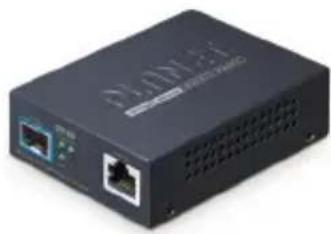
Thank you for purchasing PLANET XT-715A 10GBASE-T to 10GBASE-X SFP+ Media Converter. In the following sections, unless specified, the term "Media Converter" mentioned in this manual refers to the XT-715A.
Open the box of the Media Converter and carefully unpack it. The box should contain the following items:
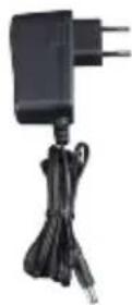
| XT-715A Media Converter x 1 | QR Code Sheet x 1 | Power Adapter (5V, 2A) x 1 |
 |  |  |
If any of these are missing or damaged, please contact your dealer immediately; if possible, retain the carton including the original packing material, and use them again to repack the product in case there is a need to return it to us for repair.

Note
The XT-715A comes with one vacant SFP module slot. The mini GBIC SFP module is not included in the package.
1.2 Product Features
- Physical Port
➢ Media conversion between 2.5G/5G/10GBASE-T and 10GBASE-X SFP+ fiber optic
➢ Copper RJ45 port supports 2.5G/5G/10GBASE-T auto-negotiation and auto-MDI/MDI-X
10GBASE-X SFP+ Fiber Optic allows
- Multi-mode fiber using LC connector
- Single-mode fiber using LC connector
- Layer 2 Features
IEEE 802.3bz/an/ae Ethernet standard compliant
➢ Non-blocking full wire-speed forwarding rate
IEEE 802.1Q tag-based VLAN transparency, multicast passthrough
16K jumbo frame
- IEEE 802.3x full-duplex and half-duplex back pressure flow control to eliminate the loss of packets
- Mechanical
Metal case
➢ LED indicators for easy network diagnostics
➢ 100 meters over Cat 6A/Cat 7 at 10Gbps RJ45 port
External 5V DC, 2A power input socket
➢ Wall mounting or DIN-rail installation (optional)
➢ 0 to 50 degrees C operating temperature
▶ Compact in size, Plug and Play installation
Best with PLANET's 10"/19" Media Converter Chassis (MC-700/MC-1500/MC-1500R/MC-1500R48)
1.3 Product Specifications
| Model XT-715A | |
| Interface | |
| Copper Port | 2.5G/5G/10GBASE-T Ethernet RJ45 interfaceAuto-negotiation, auto MDI/MDI-X |
| SFP Interface 10GBASE-X SFP+ interface | |
| Fiber Mode May vary on SFP Module | |
| Fiber Port Type (connector) | SFP, LC type |
| Fiber Maximum Distance | May vary on SFP Module |
| Network Cables | 2.5G/5G/10GBASE-T:2.5G--Cat 5e/Cat 6/Cat 6A/Cat 75G--Cat 6/Cat 6A/Cat 710G--Cat 6A/Cat 7Cat 5e/6/6A/7 UTP cable (100 meters, max.)EIA/TIA-568 100-ohm STP (100 meters.)10GBASE-X:50/125μm or 62.5/125μm multi-mode fiber optic cable, up to 300m9/125μm single-mode fiber optic cable, up to 80km |
| Hardware Specifications | |
| Enclosure Metal case | |
| Dimensions(W x D x H) | 93.5 x 70 x 26 mm |
| Weight 216g | |
| LED | System: PWR (Green)10GBASE-X SFP+ Interface: Fiber LNK/ACT (Green)10GBASE-T Ethernet Port: TP LNK/ACT (Green) |
| Power Supply DC 5V, | 2A Power Socket, external AC-to-DC adapter |
| Installation Wall-mount or DIN-rail installation (Optional) | |
| Layer 2 Features | |
| Forwarding Rate Non-blocking full wire-speed forwarding rate | |
| Flow Control | Back pressure for half duplex modeIEEE 802.3x pause frame for full duplex mode |
| Maximum Frame Size | 16K |
| Standards Conformance | |
| Regulatory Compliance | FCC Part 15 Class A, CE |
| Protocols and Standards Compliance | IEEE 802.3bz 2.5G/5GBASE-TIEEE 802.3an 10GBASE-TIEEE 802.3ae 10Gbps EthernetIEEE 802.3x Flow Control |
| Environment | |
| Temperature | Operating: 0 ~ 50 degrees CStorage: -10 ~ 70 degrees C |
| Humidity 5% ~ 95% non-condensing | |
2. Hardware Description
2.1 Physical Dimensions
- XT-715A dimensions (W x D x H): 93.5 x 70 x 26 mm
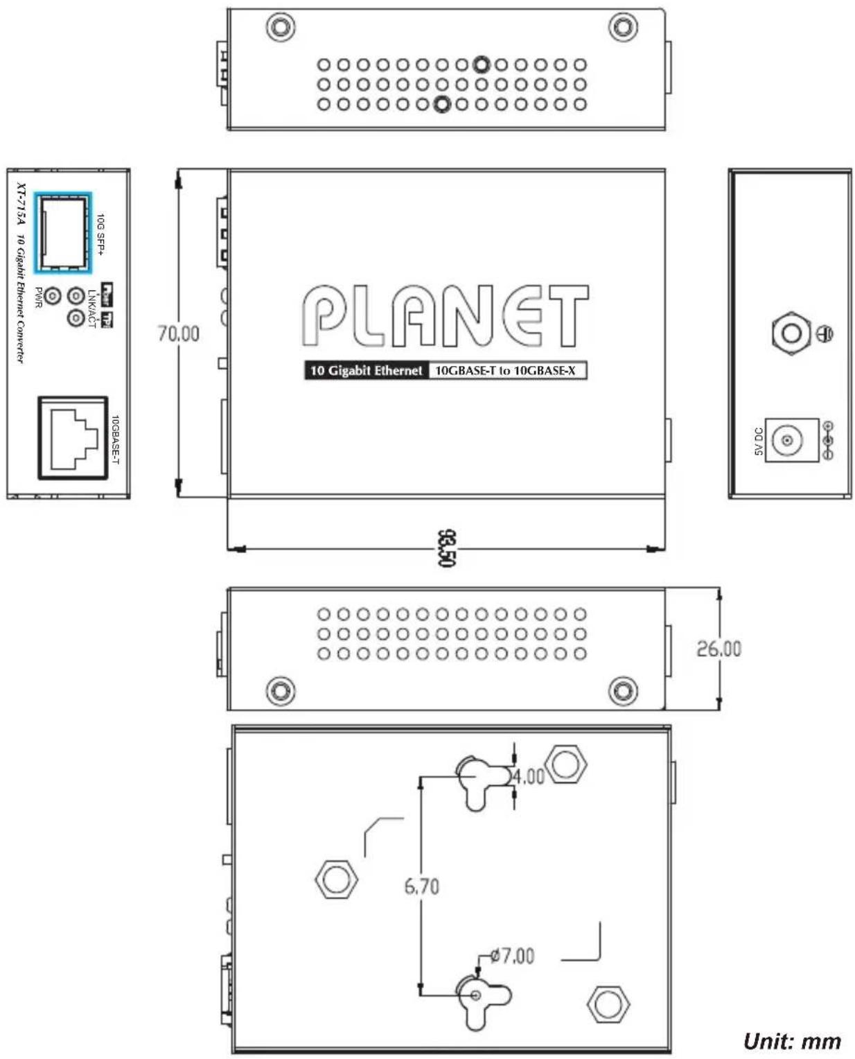
Unit: mm
Figure 2-1: XT-715A Physical Dimensions
2.2 Converter Front Panel and LED Indicators
Figure 2-2 shows the front panel of the Media Converter.
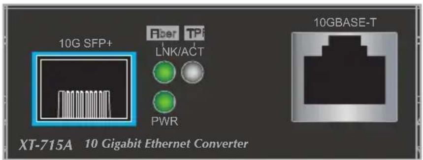
Figure 2-2: XT-715A Front Panel
System
| LED Color Function | ||
| PWR | Green | Lights to indicate the 10G Media Converter has power. |
■ 10GBASE-X SFP+ Interface
| LED Color Function | ||
| Fiber Green | Lights to indicate the link through that port is operating at 10Gbps. | |
■ 10GBASE-T Ethernet Port
| LED Color Function | |
| TP Green | Lights to indicate the link through that port is successfully established at 10Gbps.Blinks to indicate that the 10G Media Converter is actively sending or receiving data over that port. |
2.3 Rear Panel
The rear panel of the XT-715A consists of one DC jack, which accepts input power with 5V DC, 2A.
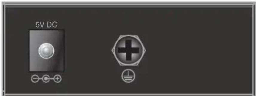
Figure 2-3: One DC jack for DC power input
2.4 Power Information:
The central pole of the Media Converter's power jacks measures 2.5mm wide that requires +5VDC power input. It conforms to the bundled AC-DC adapter and PLANET's media chassis. Should you have the issue of power connection, please contact your local sales representative.
Please keep the AC-DC adapter as a spare part when the XT-715A is installed in a media chassis.

Note
Before installing the media converter into the converter slot of PLANET media converter chassis, please remove the earth grounding screw first.
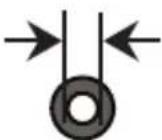
2.5mm
Width of DC Receptacle: 2.5mm
+5V for each slot

DC receptacle is 2.5mm wide that matches the central pole; the width of the Media Converter DC jack also measures 2.5mm.
Warning: Do not install any improper unit.
The device is a power-required device, meaning it will not work till it is powered. If your networks should be active all the time, please consider using UPS (Uninterrupted Power Supply) for your device. It will prevent you from network data loss or network downtime.
In some areas, installing a surge suppression device may also help to protect your Media Converter from being damaged by unregulated surge or current to the converter or the power adapter.
3. Installation
This section describes the functionalities of the Media Converter's components and guides you to how to install it on the desktop. Basic knowledge of networking is assumed. Please read this chapter completely before continuing.
3.1 Stand-alone Installation
Step 1: Unpack the Media Converter.
Step 2: Connect the 5V DC power adapter to the XT-715A and verify that the Power LED lights up.
(Please refer to the 2.4 Power Information section for power input.)
Step 3: 3-1: Prepare a twisted-pair, straight-through Category 5e/6/7 UTP cable for Ethernet connection.
3-2: Prepare a fiber cable for connection to the 10GBASE-X SFP+ slot, and make sure both sides of the SFP transceiver are with the same media type.
(Please refer to the 3.5 Cable Connection section for the type of connection.)

After RJ45 port is connected, install 10G SFP+ transceiver; the RJ45 port LNK/ACT LED will light off and on upon the re-negotiation.
Step 4: 4-1: Insert one side of Category 5e/6/7 cable into the Media Converter Ethernet port (RJ45) while the other side of Category 5e/6/7 cable into the network devices' Ethernet port (RJ45), e.g., switch, PC or server.
The UTP port (RJ45) LED on the Media Converter will light up when the cable is connected with the network device. (Please refer to the 2.2 LED Indicators section for the functions of LED lights.)
4-2: Connect the fiber cable. Attach the duplex LC connector on the network cable to the SFP+ transceiver. Attach the fiber cable from the XT-715A to the fiber network. TX, RX must be paired at both ends.
Step 5: When all the connections are all set and the LED lights all show normal, the installation is completed.

Note
- Install the 10G SFP+ transceiver into the media converter 10G SFP+ slot; the 10G SFP+ slot LNK/ACT LED will light on (Chipset restriction).
- The media converter 10G SFP+ slot will work after the 10G RJ45 port has been successfully connected.
3.2 Wall-mount Installation
Step 1: Please find the wall that can mount the Media Converter.
Step 2: Screw two screws on the wall.
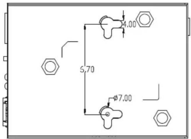
Unit: mm
Step 3: Hang the Media Converter on the screws from the wall.
Step 4: Refer to Chapter 2.4 Power Information on power supply to the Media Converter.
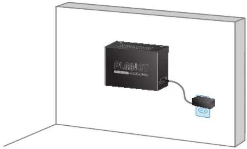
natural_image
3D rendering of a Planet device connected to a small electronic component, shown in a plain rectangular frame (no text or symbols visible)
Before mounting the device to the wall, please check the location of the electrical outlet and the length of the Ethernet cable.
3.3 Media Chassis Installation
To install the Media Converter in a 10-inch or 19-inch standard rack, follow the instructions described below.
Step 1: Place your Media Converter on a hard flat surface, with the front panel positioned towards your front side.
Step 2: Carefully slide in the module until it is fully and firmly fitted into the slot of the chassis; the Power LED of the Media Converter will turn ON.
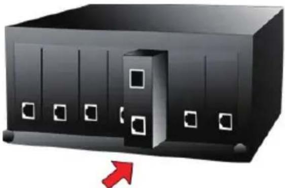
natural_image
Illustration of a server rack with a red arrow pointing to the front panel (no text or symbols)Figure 3-1: Insert Gigabit Media Converter into an available slot

Caution
- Before installing the media converter into the converter slot of PLANET media converter chassis, please remove the earth grounding screw first.
- Never push the converter into the slot with force; it could damage the chassis.
- The Media Converter Chassis supports hot-swap; there is no need to turn off the whole chassis before sliding in the new converter.
3.4 Optional DIN-rail Installation
There are two DIN-rail holes on the left side of the XT-715A that allows to be easily installed by DIN-rail mounting. PLANET optional DIN-rail mounting kit - RKE-DIN -- can be ordered separately. Refer to the following steps for the DIN-rail mounting of the XT-715A:
Step 1: Screw the DIN rail on the XT-715A.
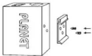
Step 2: Now slide the DIN rail into the track.
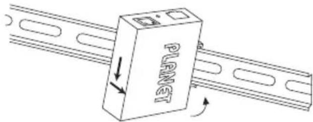
Step 3: Check whether the DIN rail is tightly on the track.
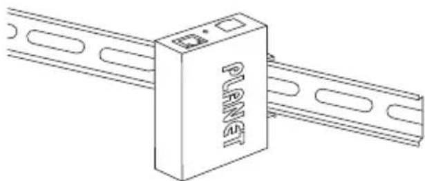
natural_image
Technical line drawing of a device labeled 'PLANET' connected to two parallel plates (no additional text or symbols)
Caution
You must use the screws supplied with the mounting brackets. Damage caused to the parts by using incorrect screws would invalidate your warranty.
3.5 Cable Connection
■ Installing the SFP+ Transceiver
The sections describe how to insert an SFP+ transceiver into an SFP+ slot.
The SFP+ transceivers are hot-pluggable and hot-swappable. You can plug in and out the transceiver to/from any SFP+ port without having to power down the Media Converter
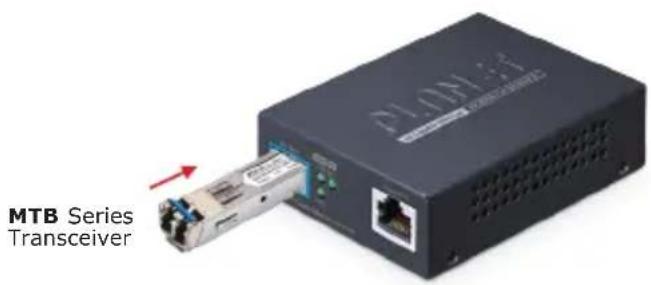
Figure 3-2: Plug in the SFP+ Transceiver

Note
It is recommended to use PLANET SFP+ transceiver on the Media Converter. If you insert an SFP+ transceiver that is not supported, the Media Converter will not recognize it.
■ 10GBASE-X SR/LR:
Before connecting the other switches, workstation or Media Converter, please do the following:
-
Make sure both sides of the SFP+ transceiver are with the same media type; for example, 10GBASE-SR to 10GBASE-SR, 10GBASE-LR to 10GBASE-LR.
-
Check whether the fiber-optic cable type matches the SFP+ transceiver model.
To connect to 10GBASE-SR SFP+ transceiver, use the multi-mode fiber cable with one side being the male duplex LC connector type.
To connect to 10GBASE-LR SFP+ transceiver, use the single-mode fiber cable with one side being the male duplex LC connector type.
■ Connecting the fiber cable
- Attach the duplex LC connector of the network cable to the SFP+ transceiver.
- Connect the other end of the cable to a device like a switch with SFP+ installed, fiber NIC on a workstation or a Media Converter.
■ Removing the Transceiver Module
- Make sure there is no network activity by consulting or checking with the network administrator. Or through the management interface of the switch/converter (if available), disable the port in advance.
- Remove the fiber optic cable gently.
- Turn the lever of the MTB module to a horizontal position.
- Pull out the module gently through the lever.
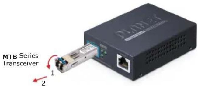
Figure 3-3: Pulling Out from the SFP+ Transceiver

Note
Never pull out the module without pulling the lever or the push bolts on the module. Directly pulling out the module with effort could damage the module and SFP+ module slot of the Media Converter.
■ 2.5G/5G/10GBASE-T
The 2.5G/5G/10GBASE-T port comes with auto-negotiation capability. It automatically supports 2.5GBASE-T, 5GBASE-T and 10GBASE-T networks. Users only need to plug a working network device into the 2.5G/5G/10GBASE-T port, and then turn on the Media Converter. The port will automatically run at 2500Mbps, 5000Mbps and 10000Mbps after the negotiation with the connected device.
Connecting the UTP Cable
The 2.5G/5G/10GBASE-T port uses RJ45 socket -- similar to phone jack -- for connection of unshielded twisted-pair cable (UTP). The IEEE 802.3bz/802.3an Ethernet standard requires Category 5e UTP while 2.5G/5G/10GBASE-T uses Cat5e/6/6A/7 UTP (see table below). Maximum distance is 100 meters (328 feet).
| Standard Transfer Speed Cable Requirement (100M) | ||
| 10GBASE-T 10000Mbit/s Cat 6A/7 | ||
| 5GBASE-T 5000Mbit/s Cat 6/6A/7 | ||
| 2.5GBASE-T 2500Mbit/s Cat 5e/6/6A/7 | ||

Note
Be sure the connected network devices support MDI/MDI-X. If it does not support, then use the crossover Category 5e/6/6A/7 cable.
APPENDIX A: Approved PLANET SFP+ Transceivers
PLANET Media Converter supports 10GBASE-X with both multi-mode and single mode SFP+ transceivers. The following list of approved PLANET SFP+ transceivers are correct at the time of publication:
Available 10Gbps SFP+ Transceivers
| MTB-RJ 1-Port 10GBASE-T SFP+ Copper Fiber Optic Module - 30m |
| MTB-SR 1-Port 10GBASE-SR SFP+ Fiber Optic Module - 300m |
| MTB-SR2 1-Port 10GBASE-SR SFP+ Fiber Optic Module - 2km |
| MTB-LR 1-Port 10GBASE-LR SFP+ Fiber Optic Module - 10km |
| MTB-LR20 1-Port 10GBASE-LR SFP+ Fiber Optic Module - 20km |
| MTB-LR40 1-Port 10GBASE-LR SFP+ Fiber Optic Module - 40km |
| MTB-LR60 1-Port 10GBASE-LR SFP+ Fiber Optic Module - 60km |
| MTB-LR80 1-Port 10GBASE-LR SFP+ Fiber Optic Module - 80km |
| MTB-LA10 1-Port 10GBASE-BX SFP+ Fiber Optic Module - 10km (TX:1270nm RX:1330nm) |
| MTB-LB10 1-Port 10GBASE-BX SFP+ Fiber Optic Module - 10km (TX:1330nm RX:1270nm) |
| MTB-LA20 1-Port 10GBASE-BX SFP+ Fiber Optic Module - 20km (TX:1270nm RX:1330nm) |
| MTB-LB20 1-Port 10GBASE-BX SFP+ Fiber Optic Module - 20km (TX:1330nm RX:1270nm) |
| MTB-LA40 1-Port 10GBASE-BX SFP+ Fiber Optic Module - 40km (TX:1270nm RX:1330nm) |
| MTB-LB40 1-Port 10GBASE-BX SFP+ Fiber Optic Module - 40km (TX:1330nm RX:1270nm) |
| MTB-LA60 | 1-Port 10GBASE-BX SFP+ Fiber Optic Module - 60km (TX:1270nm RX:1330nm) |
| MTB-LB60 | 1-Port 10GBASE-BX SFP+ Fiber Optic Module - 60km (TX:1330nm RX:1270nm) |
| MTB-LA70 | 1-Port 10GBASE-BX SFP+ Fiber Optic Module - 70km (TX:1270nm RX:1330nm) |
| MTB-LB70 | 1-Port 10GBASE-BX SFP+ Fiber Optic Module - 70km (TX:1330nm RX:1270nm) |
APPENDIX B: Networking Connection
B.1 Media Converter's RJ45 Pin Assignments
2.5G, 5G and 10GBASE-T
| Contact MDI MDI-X | |
| 1 BI_DA+ BI_DB+ | |
| 2 BI_DA- BI_DB- | |
| 3 BI_DB+ BI_DA+ | |
| 4 BI_DC+ BI_DD+ | |
| 5 BI_DC- BI_DD- | |
| 6 BI_DB- BI_DA- | |
| 7 BI_DD+ BI_DC+ | |
| 8 BI_DD- BI_DC- |
B.2 RJ45 Cable Pin Assignments
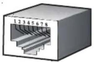
natural_image
3D diagram of a Ethernet cable connector with numbered pins (1-8) and internal structure (no text labels beyond pin numbers)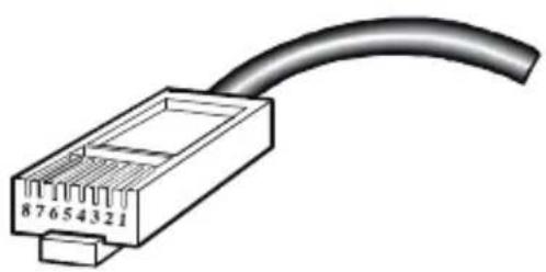
natural_image
Diagram of a 87654321 Ethernet connector with a curved cable (no text or symbols)The standard RJ45 receptacle/connector
There are 8 wires on a standard UTP/STP cable and each wire is color-coded. The following shows the pin allocation and color of straight cable and crossover cable connection:
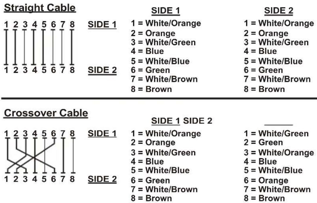
| 1 = White/Orange |
| 2 = Orange |
| 3 = White/Green |
| 4 = Blue |
| 5 = White/Blue |
| 6 = Green |
| 7 = White/Brown |
| 8 = Brown |
| 1 = White/Orange |
| 2 = Orange |
| 3 = White/Green |
| 4 = Blue |
| 5 = White/Blue |
| 6 = Green |
| 7 = White/Brown |
| 8 = Brown |
| 1 = White/Orange |
| 2 = Orange |
| 3 = White/Green |
| 4 = Blue |
| 5 = White/Blue |
| 6 = Green |
| 7 = White/Brown |
| 8 = Brown |
| 1 = White/Green |
| 2 = Green |
| 3 = White/Orange |
| 4 = Blue |
| 5 = White/Blue |
| 6 = Orange |
| 7 = White/Brown |
| 8 = Brown |
Figure B-1: Straight-through and Crossover Cables
Please make sure your connected cables are with the same pin assignment and color as the above diagram before deploying the cables into your network.
- 10GBASE-T to 10GBASE-X SFP+ Media Converter
- Trademarks
- Disclaimer
- FCC Warning
- CE Mark Warning
- WEEE Warning
- Revision
- Table of Contents
- Introduction......5
- Hardware Description....9
- Installation 13
- APPENDIX A: Approved PLANET SFP+ Transceivers.... 20
- APPENDIX B: Networking Connection.... 22
- Introduction
- Package Contents
- Product Features
- Product Specifications
- Hardware Description
- Physical Dimensions
- Converter Front Panel and LED Indicators
- Rear Panel
- Power Information:
- Installation
- Stand-alone Installation
- Wall-mount Installation
- Media Chassis Installation
- Optional DIN-rail Installation
- Cable Connection
- ■ Installing the SFP+ Transceiver
- ■ 10GBASE-X SR/LR:
- ■ Connecting the fiber cable
- ■ Removing the Transceiver Module
- ■ 2.5G/5G/10GBASE-T
- Connecting the UTP Cable
- APPENDIX A: Approved PLANET SFP+ Transceivers
- APPENDIX B: Networking Connection
- B.1 Media Converter's RJ45 Pin Assignments
- 2.5G, 5G and 10GBASE-T
- B.2 RJ45 Cable Pin Assignments
- The standard RJ45 receptacle/connector
Brand : Planet
Model : XT-715A
Category : Audio/video converter