XT-705A - Audio/video converter Planet - Free user manual and instructions
Find the device manual for free XT-705A Planet in PDF.

| Product Type | Audio/Video Converter |
| Brand | Planet |
| Model | XT-705A |
| Input Interface | HDMI (Type A) |
| Output Interface | Composite Video (RCA) + Stereo Audio (RCA) |
| Supported Resolutions | 480i, 576i, 720p, 1080i (Input); 480i, 576i (Output) |
| Video Format | NTSC / PAL (auto detect) |
| Audio Format | Stereo L/R |
| Power Supply | USB 5V / 1A (Micro USB) |
| Power Consumption | ≈ 2.5 W |
| Dimensions (L x W x H) | 10.5 x 6.0 x 2.2 cm |
| Weight | ≈ 100 g |
| Cable Length | 30 cm (HDMI to unit) |
| Operating Temperature | 0°C ~ 45°C |
| Storage Temperature | -10°C ~ 60°C |
| Compatibility | HDMI sources (DVD, STB, console) to analog TV |
| Main Functions | Convert HDMI to AV; supports 3D to 2D conversion; built-in scaler |
| Maintenance & Cleaning | Wipe with dry, soft cloth; do not use liquids |
| Safety Precautions | Keep away from water and moisture; do not disassemble |
| Spare Parts & Repairability | Non-repairable; no user-serviceable parts; replace unit if faulty |
| Certifications | CE, RoHS |
| Package Contents | Converter, USB power cable, user manual |
Frequently Asked Questions - XT-705A Planet
User questions about XT-705A Planet
0 question about this device. Answer the ones you know or ask your own.
Ask a new question about this device
Download the instructions for your Audio/video converter in PDF format for free! Find your manual XT-705A - Planet and take your electronic device back in hand. On this page are published all the documents necessary for the use of your device. XT-705A by Planet.
USER MANUAL XT-705A Planet
10G/5G/2.5G/1G/100M Copper to
10GBASE-X SFP+ Media Converter
XT-705A
User's Manual
Trademarks
Copyright © PLANET Technology Corp. 2018.
Contents are subject to revision without prior notice.
PLANET is a registered trademark of PLANET Technology Corp. All other trademarks belong to their respective owners.
Disclaimer
PLANET Technology does not warrant that the hardware will work properly in all environments and applications, and makes no warranty and representation, either implied or expressed, with respect to the quality, performance, merchantability, or fitness for a particular purpose.
PLANET has made every effort to ensure that this User's Manual is accurate; PLANET disclaims liability for any inaccuracies or omissions that may have occurred.
Information in this User's Manual is subject to change without notice and does not represent a commitment on the part of PLANET. PLANET assumes no responsibility for any inaccuracies that may be contained in this User's Manual. PLANET makes no commitment to update or keep current the information in this User's Manual, and reserves the right to make improvements to this User's Manual and/or to the products described in this User's Manual, at any time without notice.
If you find information in this manual incorrect, misleading, or incomplete, we would appreciate your comments and suggestions.
FCC Warning
This equipment has been tested and found to comply with the limits for a Class A digital device, pursuant to Part 15 of the FCC Rules. These limits are designed to provide reasonable protection against harmful interference when the equipment is operated in a commercial environment. This
equipment generates, uses, and can radiate radio frequency energy and, if not installed and used in accordance with the Instruction manual, may cause harmful interference to radio communications. Operation of this equipment in a residential area is likely to cause harmful interference in which case the user will be required to correct the interference at his own expense.
CE Mark Warning
This is a Class A product. In a domestic environment, this product may cause radio interference, in which case the user may be required to take adequate measures.
WEEE Warning
To avoid the potential effects on the environment and human health as a result of the presence of hazardous substances in electrical and electronic equipment, end users of electrical and electronic equipment should understand the meaning of the crossed-out wheeled bin symbol. Do not dispose of WEEE as unsorted municipal waste and have to collect such WEEE separately.
Revision
PLANET 10G/5G/2.5G/1G/100M Copper to 10GBASE-X SFP+ Media Converter User's Manual
Model: XT-705A
Revision: 1.0 (April, 2018)
Part No: EM-XT_705A_v1.0 (2350-AA5010-000)
Table Of Contents
1. Introduction .... 5
1.1 Package Contents....5
1.2 Product Overview....6
1.3 Product Features....7
1.4 Product Specifications....8
2. Hardware Description.... 11
2.1 Physical Dimensions 11
2.2 Converter Front Panel and LED Indicators 12
2.3 Rear Panel.... 13
2.4 Power Information: 13
3. Installation.... 15
3.1 Stand-alone Installation.... 15
3.2 Wall-mount Installation.... 16
3.3 Media Chassis Installation.... 17
3.4 Optional DIN-rail Installation 18
3.5 Cable Connection 19
4. Troubleshooting 23
Appendix A: Approved PLANET SFP+ Transceivers 25
Appendix B: Networking Connection 26
B.1 Converter's RJ45 Pin Assignments 26
B.2 RJ45 Cable Pin Assignments 27
1. Introduction
1.1 Package Contents
Thank you for purchasing PLANET 10G Media Converter. In the following sections, unless specified, the term "Media Converter" mentioned in this manual refers to the XT-705A.
Open the box of the Media Converter and carefully unpack it. The box should contain the following items:
| XT-705A Media Converter x 1 User's Manual x 1 | |
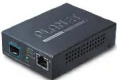 | 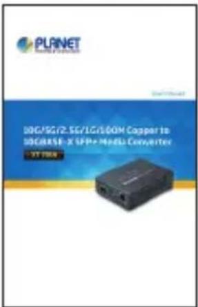 |
| Power adapter (5V, 2.5A) x 1 | |
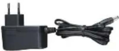 | |
If any of these are missing or damaged, please contact your dealer immediately; if possible, retain the carton including the original packing material, and use them again to repack the product in case there is a need to return it to us for repair.
1.2 Product Overview
Flexible and Reliable Network Distance Extension Solution
PLANET XT-705A Media Converter is equipped with one 10G/5G/2.5G/1G/100BASE-T auto-negotiation port and one 10GBASE-X SFP+ slot. It supports 10Gigabit Ethernet media conversion from copper 10GBASE-T to fiber multi-mode or single-mode, utilizing 10GBASE-SR or 10GBASE-LR SFP+ transceiver installed in the SFP+ slot to extend distances to servers, switches and patch panels. The deployment distance can be extended from 300 meters (multi-mode) to up to 60 kilometers (single-mode). They are designed for use in network environments where the ultra-high bandwidth provided by 10Gigabit Ethernet is required, for example, data center cloud computing, enterprise backbones, campus networks, and carrier infrastructure.
High Performance 10Gbps Ethernet Capacity
The XT-705A offers wire-speed packets transfer performance without risk of packet loss. The high data throughput of the device makes it ideal for most Gigabit environments. With a 20Gbps internal fabric and featuring auto negotiation support in its 10 Gigabit port, the XT-705A Media Converter can handle large amounts of data in a secure topology linking to a backbone or high capacity servers.
Fiber-optic Linking Capability Enables Extension of Network Deployment
The SFP+ slot of the XT-705AT is compatible with 10GBASE-SR or 10GBASE-LR (Small Form Factor Pluggable) fiber-optic transceivers. The fiber optic uplink capability guarantees the throughput to all nodes hooked into the network and the 10 Gigabit Ethernet distance can be extended from 300 meters (multi-mode fiber cable) to 10/40/60 kilometers (single-mode
fiber cable). It is ideal for applications within the data centers and distributions.
Easy Chassis Installation
The XT-705A Media Converter can be used as a stand-alone unit or as a slide-in module to the PLANET Media Converter Chassis (MC-700 and MC-1500 chassis series). The media chassis can assist in providing DC power to the XT-705A Media Converter to maintain the fiber-optic network at one centralized location. It can be DIN-rail or wall mounted for efficient use of cabinet space.
Low Power Consumption
The XT-705A adopting the advanced chip technology has the power-saving feature like a low power consumption of only 3.75 watts when in full operation.
1.3 Product Features
XT-705A Physical Port
■ One 10G/5G/2.5G/1G/100BASE-T RJ45 interface with auto MDI/MDI-X function
■ One 10GBASE-X SFP+ slot
Layer 2 Features
■ IEEE 802.3u/802.3ab/802.3bz/802.3ae Ethernet standard compliant
■ Supports auto-negotiation and 100Mbps half/full duplex and 1/2.5/5/10Gbps full duplex mode
■ Prevents packet loss with back pressure (half-duplex) and IEEE 802.3x pause frame flow control (full-duplex)
■ 16K jumbo frame size support
■ Automatic address learning and address aging
Case and Installation
■ External 5V DC, 2.5A power supply
■ DIN-rail and wall-mount design
■ Supports 6000 VDC Ethernet ESD protection
■ 100 meters over Cat 6A / Cat7 at 10Gbps
■ 0 to 50 degrees C operating temperature
■ Co-works with PLANET's 10"/19" Media Converter Chassis (MC-700/MC-1500/MC-1500R/MC-1500R48)
■ Plug and Play installation
1.4 Product Specifications
| Model XT-705A | |
| Hardware Specifications | |
| Copper Interface | 1 x 10G/5G/2.5G/1G/100BASE-T RJ45 Auto-MDI/MDI-X, auto-negotiation |
| Fiber Optic Interface | 1 x 10GBASE-X R SFP+ interface. |
| LED | System: PWR (Green) 10G/5G/2.5G/1G/100 BASE-T RJ45 Interfaces: 1G/10G LNK (Orange) 5G/2.5G/100M LNK (Green) |
| Switch Processing Scheme | Store and Forward |
| ESDProtection | 6KV DC |
| Enclosure Compact-sized metal case | |
| Installation | Desktop, wall mountableMedia convert Chassis installationOptional DIN-rail kit |
| Dimensions(WxDxH) | 94 x 70 x 26mm |
| Weight 180g (device only) | |
| Power Requirements | 5V DC, 2A max. |
| Power Consumption | 3.75 watts / 12.8 BTU per hour max. |
| Converter Specifications | |
| Flow Control | Back pressure for half duplexIEEE 802.3x pause frame for full duplex |
| Fabric 20Gbps | |
| Throughput(packet per second) | 2.48Mpps@64bytes |
| Address Table | 9K entries, automatic source address learning and aging |
| Jumbo Frame 1 | 6K |
| Network Cables | 10G/5G/2.5G/1G/100M BASE-T:10G--Cat 6A/Cat 75G--Cat 6/Cat 6A/Cat 71G/2.5G--Cat 5e/Cat 6/Cat 6A/ Cat 7100M--Cat 5/Cat 5e/Cat 6/Cat 6A/ Cat 7Cat 5/5e/6/6A/7 UTP cable (100 meters, max.)EIA/TIA-568 100-ohm STP (100 meters, max.)10GBASE-LR/SR/BX :50/125μm or 62.5/125μm multi-mode fiber optic cable, up to 300m9/125μm single-mode fiber optic cable, up to 60km |
| Standards Conformance | |
| Regulatory Compliance | FCC Part 15 Class A, CE |
| Operating environment | 0 ~ 50 degrees C |
| Storage environment | -10 ~ 70 degrees C |
| Operating Humidity | 5 ~ 95%, relative humidity (non-condensing) |
| Storage Humidity | 5 ~ 95%, relative humidity (non-condensing) |
| Standards Compliance | IEEE 802.3u 100BASE-TXIEEE 802.3ab 1000BASE-TIEEE 802.3bz 2.5G/5GBASE-TIEEE 802.3an 10GBASE-TIEEE 802.3ae 10Gbps EthernetIEEE 802.3x full-duplex flow control |
2. Hardware Description
2.1 Physical Dimensions
XT-705A dimensions (W x D x H): 94 x 70 x 26mm
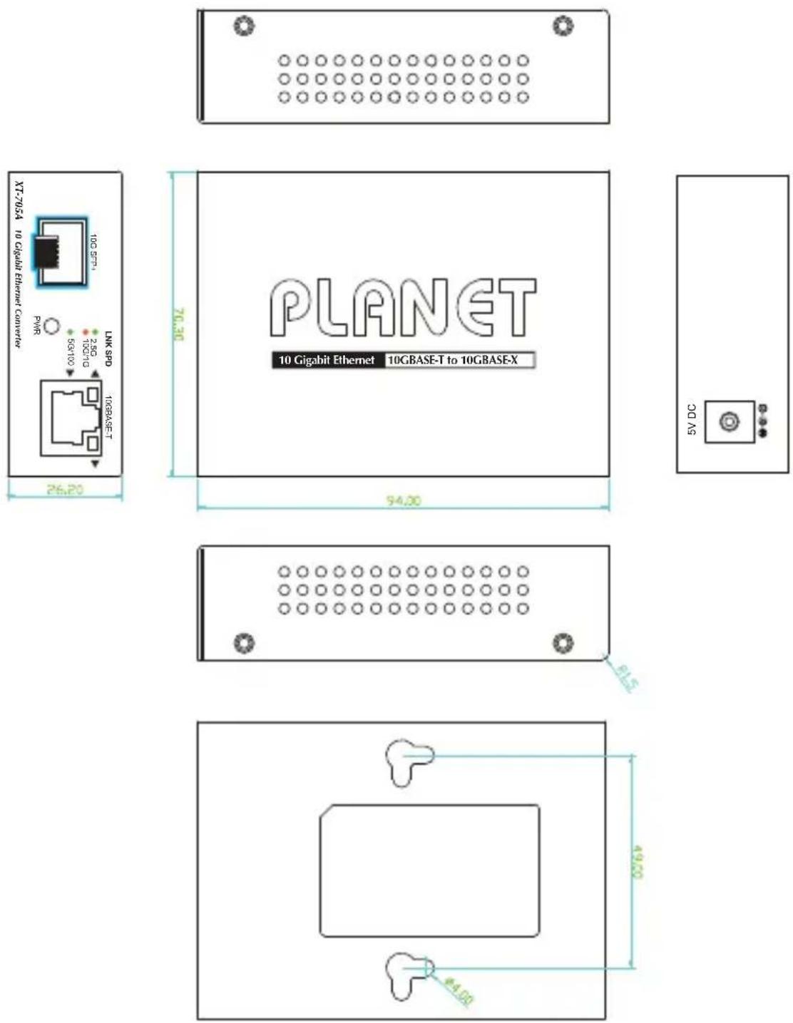
Dimensions (unit = mm)
2.2 Converter Front Panel and LED Indicators
Figure 2-2 shows the front panels of the Media Converter.
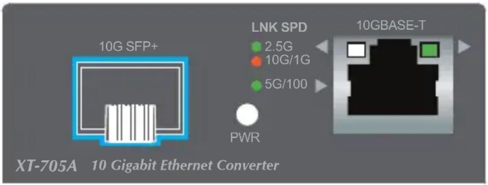
Figure 2-2: XT-705A Front Panel
System
| LED Color Function | ||
| PWR Green | Lit: Power is active | |
| Off: Power is inactive | ||
Per 10G/5G/2.5G/1G/100BASE-T Port
| LED Color Function | ||
| 10/2.5/1G | Green | Lit: To indicate that the port is operating at 2.5Gbps. |
| Orange | Lit: To indicate that the port is operating at 10/1Gbps. | |
| 5G/100M | Green | Off: To indicate that the port is operating at 5Gbps/100Mbps. |
2.3 Rear Panel
The rear panel of the XT-705A consists of one DC jack, which accepts input power with 5V DC, 2A.

Figure 2-3: One DC jack for DC power input
2.4 Power Information:
The central pole of the Media Converter's power jacks measures 2.5mm wide that require +5VDC power input. It conforms to the bundled AC-DC adapter and PLANET's media chassis. Should you have the issue of power connection, please contact your local sales representative.
Please keep the AC-DC adapter as a spare part when the XT-705A is installed in a media chassis.
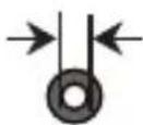
2.5mm
Width of DC Receptacle: 2.5mm
+5V for each slot

DC receptacle is 2.5mm wide that matches the central pole; the width of the Media Converter DC jack also measures 2.5mm.
Warning: Do not install any improper unit.Converter.
The device is a power-required device, meaning it will not work till it is powered. If your networks should be active all the time, please consider using UPS (Uninterrupted Power Supply) for your device. It will prevent you from network data loss or network downtime.
In some areas, installing a surge suppression device may also help to protect your Media Converter from being damaged by unregulated surge or current to the converter or the power adapter.
3. Installation
This section describes the functionalities of the Media Converter's components and guides you to how to install it on the desktop. Basic knowledge of networking is assumed. Please read this chapter completely before continuing.
3.1 Stand-alone Installation
Step 1: Unpack the Media Converter.
Step 2: Connect the 5V DC power adapter to the XT-705A and verify that the Power LED lights up.
(Please refer to the 2.4 Power Information section for power input.)
Step 3:
3-1: Prepare a twisted-pair, straight-through Category 5e/6/7 UTP cable for Ethernet connection.
3-2: Prepare a fiber cable for connection to the 10GBASE-T SFP+ slot, and make sure both sides of the SFP transceiver are with the same media type.
(Please refer to the 3.5 Cable Connection section for the type of connection.)
Step 4:
4-1: Insert one side of Category 5e/6/7 cable into the Media Converter Ethernet port (RJ45) while the other side of Category 5e/6/7 cable into the network devices' Ethernet port (RJ45), e.g., switch, PC or server.
The UTP port (RJ45) LED on the Media Converter will light up when the cable is connected with the network device. (Please refer to the 2.2 LED Indicators section for the functions of LED lights.)
4-2: Connect the fiber cable. Attach the duplex LC connector on the network cable to the SFP+ transceiver. Attach the fiber cable from the XT-705A to the fiber network. TX, RX must be paired at both ends.
Step 5: When all the connections are all set and the LED lights all show normally, the installation is complete.
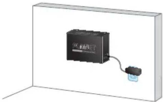
3.2 Wall-mount Installation
Step 1: Please find the wall that can mount the Media Converter
Step 2: Screw two screws on the wall.
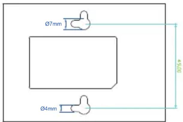
XT-705A Switch Bottom Side
Step 3: Hang the Media Converter on the screws from the wall.
Step 4: Refer to Chapter 2.4 Power Information on power supply to the Media Converter.
natural_image
3D rendering of a black rectangular device connected to a small blue connector, enclosed in a white rectangular frame (no text or symbols visible)
Before mounting the device to the wall, please check the location of the electrical outlet and the length of the Ethernet cable.
3.3 Media Chassis Installation
To install the Media Converter in a 10-inch or 19-inch standard rack, follow the instructions described below.
Step 1: Place your Media Converter on a hard flat surface, with the front panel positioned towards your front side.
Step 2: Carefully slide in the module until it is fully and firmly fitted into the slot of the chassis; the Power LED of the Media Converter will turn ON.
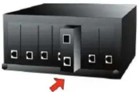
natural_image
3D illustration of a black rectangular device with white square buttons and a red arrow pointing to its side (no text or symbols)Figure 3-2: Insert Gigabit Media Converter into an available slot

Caution
-
Never push the converter into the slot with force; it could damage the chassis.
-
The Media Converter Chassis supports hot-swap; there is no need to turn off the whole chassis before sliding in the new converter.
3.4 Optional DIN-rail Installation
There are two DIN-rail holes on the left side of the XT-705A that allows to be easily installed by DIN-rail mounting. PLANET optional DIN-rail mounting kit – RKE-DIN -- can be ordered separately. Refer to the following steps for the DIN-rail mounting of the XT-705A:
Step 1: Screw the DIN rail on the XT-705A
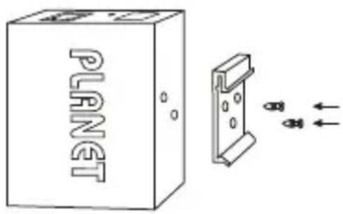
Step 2: Now slide the DIN rail into the track.
Step 3: Check whether the DIN rail is tightly on the track.
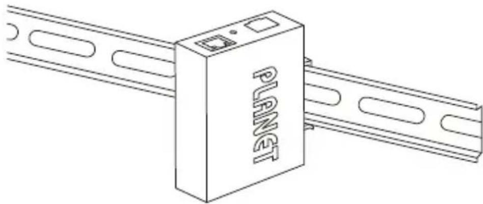
natural_image
Line drawing of a device labeled 'PLAET' connected to a metal rail (no additional text or symbols)
Caution
You must use the screws supplied with the mounting brackets. Damage caused to the parts by using incorrect screws would invalidate your warranty.
3.5 Cable Connection
■ Installing the SFP+ Transceiver
The sections describe how to insert an SFP+ transceiver into an SFP+ slot.
The SFP+ transceivers are hot-pluggable and hot-swappable. You can plug in and out the transceiver to/from any SFP+ port without having to power down the Media Converter
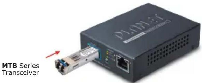
Figure 3-5-1: Plug in the SFP+ Transceiver

It is recommended to use PLANET SFP+s on the Media Converter. If you insert an SFP+ transceiver that is not supported, the Media Converter will not recognize it.
10GBASE-X SR/LR:
Before connecting the other switches, workstation or Media Converter, please do the following:
-
Make sure both sides of the SFP+ transceiver are with the same media type; for example, 10GBASE-SR to 10GBASE-SR, 10GBASE-LR to 10GBASE-LR.
-
Check whether the fiber-optic cable type matches the SFP+ transceiver model.
To connect to 10GBASE-SR SFP+ transceiver, use the multi-mode fiber cable with one side being the male duplex LC connector type.
To connect to 10GBASE-LR SFP+ transceiver, use the single-mode fiber cable with one side being the male duplex LC connector type.
Connecting the fiber cable
-
Attach the duplex LC connector of the network cable to the SFP+ transceiver.
-
Connect the other end of the cable to a device like a switch with SFP+ installed, fiber NIC on a workstation or a Media Converter.
■ Removing the Transceiver Module
- Make sure there is no network activity by consulting or checking with the network administrator. Or through the management interface of the switch/converter (if available),
disable the port in advance.
- Remove the fiber optic cable gently.
- Turn the lever of the MTB module to a horizontal position.
- Pull out the module gently through the lever.
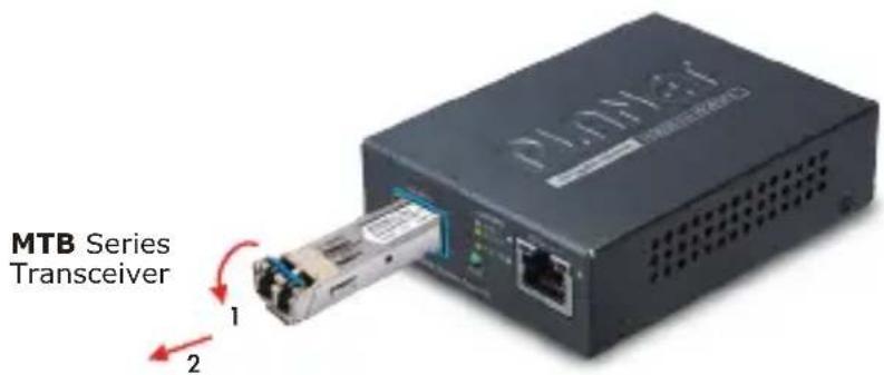
Figure 3-5-2: Pulling Out from the Transceiver

Never pull out the module without pulling the lever or the push bolts on the module. Directly pulling out the module with effort could damage the module and SFP+ module slot of the Media Converter.
10G/5G/2.5G/1G/100BASE-T
The 10G/5G/2.5G/1G/100BASE-T port comes with auto-negotiation capability. It automatically supports 100BASE-TX, 1GBASE-T, 2.5GBASE-T, 5GBASE-T and 10GBASE-T networks. Users only need to plug a working network device into the 10G/5G/2.5G/1G/100BASE-T port, and then turn on the Media Converter. The port will automatically run at 100Mbps, 1000Mbps, 2500Mbps or 5000Mbps and 10000Mbps after the negotiation with the connected device.
Connecting the UTP Cable
The 10G/5G/2.5G/1G/100BASE-T port uses RJ45 socket -- similar to phone jack -- for connection of unshielded twisted-pair cable (UTP). The 802.3u/802.3ab/802.3bz/802.3ae Ethernet standard requires Category 5 UTP for 100Mbps 100BASE-TX. 10G/5G/2.5G/1G/100BASE-T uses Cat5e/6/6A/7 UTP (see table below). Maximum distance is 100 meters (328 feet).
| Standard Transfer Speed Cable | Requirement (100M) |
| 10GBASE-T 10000Mbit/s Cat 6A/7 | |
| 5GBASE-T 5000Mbit/s Cat 6/6A/7 | |
| 2.5GBASE-T 2500Mbit/s Cat 5e/6 | /6A/7 |
| 1000BASET 1000Mbit/s Cat 5e/6 | /6A/7 |
| 100BASE-TX 100Mbit/s Cat 5/5e | /6/6A/7 |

Note
Be sure the connected network devices support MDI/MDI-X. If it does not support, then use the crossover Category 5e6/6A/7 cable.
4. Troubleshooting
This chapter contains information to help you solve issues. If the Media Converter is not functioning properly, make sure the Media Converter is set up according to instructions in this manual.
The per port LED is not lit
Solution:
Check the cable connection of the Media Converter.
Performance is bad
Solution:
Check the speed duplex mode of the partner device. The Media Converter usually runs in auto-negotiation mode. If the partner is set to half duplex, the performance will be poor.
Per port LED is lit, but the traffic is irregular
Solution:
Check that the attached device is not set to dedicate full duplex. Some devices use a physical or software switch to change duplex modes. Auto-negotiation may not recognize this type of full-duplex setting.
Why the Media Converter doesn't connect to the network
Solution:
Check per port LED on the Media Converter. Make sure the cable is installed properly. Make sure the cable is the right type. Turn off the power. After a while, turn on the power again.
Can I install MTB-TSR or the other industrial-grade SFP+ module with non-wide temperature feature into the SFP+ slot of Media Converter?
Solution:
Yes, you can. However, the XT-705A features non-wide temperature, meaning it cannot be operated with temperature ranging from -40 to 75 degrees C.
PLANET recommends customers to use the IXT-705AT industrial-grade 10G Media Converter with the wide-ranging operating temperature feature.
Appendix A: Approved PLANET SFP+
Transceivers
PLANET Media Converter supports 100/1000 dual mode with both single mode and multi-mode SFP+ transceivers. The following list of approved PLANET SFP+ transceivers is correct at the time of publication:
Available 10Gbps Modules
| MTB-RJ 10 | GBASE-T SFP+ Copper Fiber Optic Module - 30m |
| MTB-SR 10 | GBASE-SR mini-GBIC module - 300m |
| MTB-LR 10 | GBASE-LR mini-GBIC module - 10km |
| MTB-TSR | 10GBASE-SR mini-GBIC module - 300m (-40~75 degrees C) |
| MTB-TLR | 10GBASE-LR mini-GBIC module - 10km (-40~75 degrees C) |
| MTB-LA20 | 10GBASE-LX (WDM,TX:1270nm) mini-GBIC module - 20km |
| MTB-LB20 | 10GBASE-LX (WDM,TX:1330nm) mini-GBIC module - 20km |
| MTB-LA40 | 10GBASE-LX (WDM,TX:1270nm) mini-GBIC module - 40km |
| MTB-LB40 | 10GBASE-LX (WDM,TX:1330nm) mini-GBIC module - 40km |
| MTB-LA60 | 10GBASE-LX (WDM,TX:1270nm) mini-GBIC module - 60km |
| MTB-LB60 | 10GBASE-LX (WDM,TX:1330nm) mini-GBIC module - 60km |
Appendix B: Networking Connection
B.1 Converter's RJ45 Pin Assignments
1G, 2.5G, 5G and 10GBASE-T
| PIN NO MDI MDI-X | |
| 1 BI_DA+ BI_DB+ | |
| 2 BI_DA- BI_DB- | |
| 3 BI_DB+ BI_DA+ | |
| 4 BI_DC+ BI_DD+ | |
| 5 BI_DC- BI_DD- | |
| 6 BI_DB- BI_DA- | |
| 7 BI_DD+ BI_DC+ | |
| 8 BI_DD- BI_DC- |
100Mbps, 100BASE-TX
| RJ45 Connector Pin Assignment | ||
| Contact | MDIMedia DependentInterface | MDI-XMedia DependentInterface -- Cross |
| 1 Tx | + (transmit) Rx + (receive) | |
| 2 Tx | + (transmit) Rx - (receive) | |
| 3 Rx | + (receive) Tx + (transmit) | |
| 4, 5 | Not used | |
| 6 | Rx - (receive) | Tx - (transmit) |
| 7, 8 | Not used | |
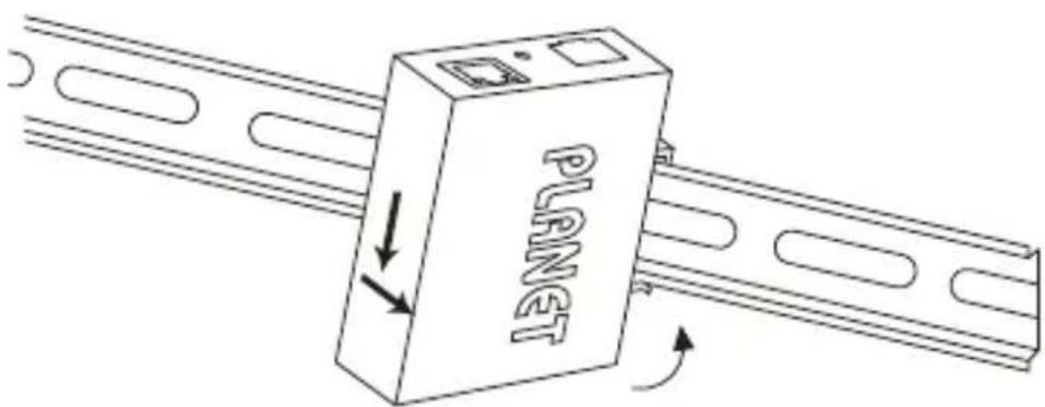
B.2 RJ45 Cable Pin Assignments
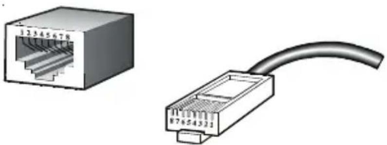
natural_image
Two types of Ethernet connectors shown: a separate network interface and a straight cable (no text or symbols)The standard RJ45 receptacle/connector
There are 8 wires on a standard UTP/STP cable and each wire is color-coded. The following shows the pin allocation and color of straight cable and crossover cable connection:
| Straight Cable | SIDE 1 | SIDE 2 | |
| 1 2 3 4 5 6 7 8 1 2 3 4 5 6 7 8 | SIDE 1 | 1 = White/Orange 2 = Orange 3 = White/Green 4 = Blue 5 = White/Blue | 1 = White/Orange 2 = Orange 3 = White/Green 4 = Blue 5 = White/Blue |
| SIDE 2 | 6 = Green 7 = White/Brown 8 = Brown | 6 = Green 7 = White/Brown 8 = Brown | |
| Crossover Cable | SIDE 1 SIDE 2 | ||
| 1 2 3 4 5 6 7 8 1 2 3 4 5 6 7 8 | SIDE 1 | 1 = White/Orange 2 = Orange 3 = White/Green 4 = Blue 5 = White/Blue | 1 = White/Green 2 = Green 3 = White/Orange 4 = Blue 5 = White/Blue |
| SIDE 2 | 6 = Green 7 = White/Brown 8 = Brown | 6 = Orange 7 = White/Brown 8 = Brown | |
Figure B-1: Straight-through and Crossover Cables
Please make sure your connected cables are with the same pin assignment and color as the above diagram before deploying the cables into your network.
EC Declaration of Conformity
For the following equipment:
*Type of Product : 10G/5G/2.5G/1G/100M Copper to 10GBASE-X SFP+ Media Converter
*Model Number : XT-705A
* Produced by:
Manufacturer's Name : Planet Technology Corp.
Manufacturer's Address : 10F., No.96, Minquan Rd., Xindian Dist.,
New Taipei City 231, Taiwan, R.O.C.
is herewith confirmed to comply with the requirements set out in the Council Directive on the Approximation of the Laws of the Member States relating to Electromagnetic Compatibility Directive on 2014/30/EU.
For the evaluation regarding the EMC, the following standards were applied:
EN 55032
(2015 + AC:2016)
EN 61000-3-2 (2014)
EN 61000-3-3
(2013)
EN 55024 (2010 + A1:2015)
Responsible for marking this declaration if the:
Manufacturer
☐ Authorized representative established within the EU
Authorized representative established within the EU (if applicable):
Company Name: Planet Technology Corp.
Company Address: 10F., No.96, Minquan Rd., Xindian Dist., New Taipei City 231, Taiwan, R.O.C.
Person responsible for making this declaration
Name, Surname Kent Kang
Position / Title : Director
Taiwan
Place
May 16, 2018
Date

Legal Signature
- 10G/5G/2.5G/1G/100M Copper to
- 10GBASE-X SFP+ Media Converter
- Trademarks
- Disclaimer
- FCC Warning
- CE Mark Warning
- WEEE Warning
- Revision
- Table Of Contents
- Introduction .... 5
- Hardware Description.... 11
- Installation.... 15
- Troubleshooting 23
- Appendix A: Approved PLANET SFP+ Transceivers 25
- Appendix B: Networking Connection 26
- Introduction
- Package Contents
- Product Overview
- Flexible and Reliable Network Distance Extension Solution
- High Performance 10Gbps Ethernet Capacity
- Fiber-optic Linking Capability Enables Extension of Network Deployment
- Easy Chassis Installation
- Low Power Consumption
- Product Features
- XT-705A Physical Port
- Layer 2 Features
- Case and Installation
- Product Specifications
- Hardware Description
- Physical Dimensions
- Converter Front Panel and LED Indicators
- Rear Panel
- Power Information:
- Installation
- Stand-alone Installation
- Step 3:
- Step 4:
- Wall-mount Installation
- Media Chassis Installation
- Optional DIN-rail Installation
- Cable Connection
- ■ Installing the SFP+ Transceiver
- 10GBASE-X SR/LR:
- Connecting the fiber cable
- ■ Removing the Transceiver Module
- 10G/5G/2.5G/1G/100BASE-T
- Connecting the UTP Cable
- Troubleshooting
- The per port LED is not lit
- Performance is bad
- Per port LED is lit, but the traffic is irregular
- Why the Media Converter doesn't connect to the network
- Can I install MTB-TSR or the other industrial-grade SFP+ module with non-wide temperature feature into the SFP+ slot of Media Converter?
- Appendix A: Approved PLANET SFP+
- Transceivers
- Appendix B: Networking Connection
- B.1 Converter's RJ45 Pin Assignments
- B.2 RJ45 Cable Pin Assignments
- EC Declaration of Conformity
Brand : Planet
Model : XT-705A
Category : Audio/video converter