USER MANUAL AMSTERDAM TCM 127 BLAUPUNKT
natural_image
Close-up of hands assembling electronic components on a circuit board (no visible text or symbols)
8 622 400 963

BLAUPUNKT
Bosch Gruppe
Sicherheitshinweise
Masseanschluß (Ground)
natural_image
Pure electrical circuit lines without any symbols
braun / Masse
natural_image
Pure electrical circuit lines without any symbols
natural_image
Line drawing of a cable or cable connection with two labeled components, no text or symbols present
Fitting instructions Instructions de montage Istruzioni di montaggio Inbouwinstrukties Monteringsanvisning Instrucciones de montaje Instruções de montagem
GB Safety notes
Before starting to mount your car radio, read the mounting and connection instructions carefully.
Disconnect the vehicle battery's negative terminal before making connections. Be sure to observe the safety notes of the automobile manufacturer (airbags, alarm systems, on-board computers, immobilisers).
Before drilling holes, look to see what is on the other side - making holes into the battery, wiring looms or fuse box is not recommended!
The positive lead used must have a cross-section of at least 2.5 mm^2 . The set is protected by a quick-acting 10 A fuse.
During operation of the unit, the set's side wall may heat up considerably.
Be sure to keep all wires away from hot parts of the housing.
In some vehicles you will find a 20-pin connector pre-fitted in the dashboard's installation space. This connector must not be used for connecting the car radio! In vehicles manufactured by Audi and VW, the 8-pin positive/negative connector provided in the car must not be connected to a Blaupunkt radio directly! Otherwise the permanent +12 V line will be short-circuited to ground, leading to serious damage of the radio's internal circuitry (burn-out of printed conductor).
natural_image
Technical line drawings of various electronic components and connectors (no text or symbols)
This product must be installed by an authorised Bosch serviceworkshop only.
Cable Routing
IMPORTANT In vehicles equipped with electronically controlled anti-lock braking systems, route all cables on the opposite side of the vehicle from the braking modular box. This will reduce any possible interference from the car kit.
- Mount the external antenna on the opposite side of the vehicle, to that which the braking modular box is located.
- Route all cables on the opposite side of the vehicle from the braking modulator box.
Possible Interference With Anti-Lock Braking Systems
Performance of electronically controlled brake and/or guidance systems can, under certain conditions, be subject to interference by radio telephone operation. Although the radio meets or exceeds all RF emission requirements, the RF power emitted from the antenna cannot be eliminated without seriously affecting the radio's operation. All automotive control systems have to meet stringent EMI specifications, but a defective control system may go undetected until it becomes necessary to operate in the proximity of a transmitting antenna.
Therefore, electronically controlled brake an/or guidance systems should be checked very carefully and at different speeds for any sign of abnormal operation. See Section 4 for further information on performance verification.
Checking Anti-Skid Braking Systems
The test procedure is divided into eight different checks in order to cover various types of interference. Disturbance of an electronic anti-skid braking system can usually be detected in several different ways: e.g., the lights, irregular audible sounds, notice able changes in the braking system's performance, etc.
-
With the car stationary in neutral, the engine running at fast idle, and your foot off the brake pedal, make a phone call.
-
Repeat the previous check but with your foot on the brake pedal.
- With the car stationary, and with at least several car lengths of clear area in front of the vehicle, engage a forward gear. Bring the clutch up to the biting point whilst preventing forward motion by applying gentle pressure to the brake pedal. Help may be required to achieve the above. Make a call and ensure no malfunctions are observed.
- With your foot off the brake pedal and driving at a moderate speed of 15 to 25 mph (24 to 40 km/hour), have the phone called.
- With your foot exerting slight pressure in the brake pedal, enough to turn on the brake lights, have the phone called.
- While making moderate deceleration stops from 25 to 30 mph (40 to 48 km/hour), have the phone called.
CAUTION Severe disruption of the electronic anti-skid braking system may cause loss of control of the vehicle while performing the following test.
-
While making an ‘emergency’ type stop from 20 mph (32 km/our), have the phone called.
-
If no interference occurs, repeat check 7 doing an 'emergency' type stop from 30 mph (48 km/hour).
IMPORTANT If no malfunctions are observed while performing any of the previous tests, it can be assumed that no apparent problems exist and the vehicle can be released to the customer. However, if any of the tests cause a brake malfunction, any further tests should be stopped, and the phone removed from the vehicle immediately. Then contact the vehicle manufacturer's service department as soon as possible to seek further advise.
flowchart
graph TD
    A["Warehouse"] --> B["Truck"]
    B --> C["Route 1: 20+1/20"]
    B --> D["Route 2: 20+1/20"]
    B --> E["Route 3: 20+1/20"]
    B --> F["Route 4: 20+1/20"]
    B --> G["Route 5: 20+1/20"]
    B --> H["Route 6: 20+1/20"]
    B --> I["Route 7: 20+1/20"]
    B --> J["Route 8: 20+1/20"]
    B --> K["Route 9: 20+1/20"]
    B --> L["Route 10: 20+1/20"]
    style A fill:#f9f,stroke:#333
    style B fill:#ccf,stroke:#333
    style C fill:#cfc,stroke:#333
    style D fill:#cfc,stroke:#333
    style E fill:#cfc,stroke:#333
    style F fill:#cfc,stroke:#333
    style G fill:#cfc,stroke:#333
    style H fill:#cfc,stroke:#333
    style I fill:#cfc,stroke:#333
    style J fill:#cfc,stroke:#333
    style K fill:#cfc,stroke:#333
flowchart
graph TD
    A["Device 1"] --> B["Switch"]
    B --> C["Power Line"]
    B --> D["Terminal Block"]
    C --> E["+12V"]
    C --> F["-5"]
    C --> G["+12V"]
    C --> H["-5"]
    C --> I["+12V/K15"]
    style A fill:#f9f,stroke:#333
    style B fill:#ccf,stroke:#333
    style C fill:#cfc,stroke:#333
flowchart
graph TD
    A["Device"] --> B["Port 1"]
    A --> C["Port 2"]
    A --> D["Port 3"]
    A --> E["Port 4"]
    A --> F["Port 5"]
    A --> G["Port 6"]
    A --> H["Port 7"]
    A --> I["Port 8"]
    A --> J["Port 9"]
    A --> K["Port 10"]
    A --> L["Port 11"]
    A --> M["Port 12"]
    A --> N["Port 13"]
    A --> O["Port 14"]
    A --> P["Port 15"]
    A --> Q["Port 16"]
    A --> R["Port 17"]
    A --> S["Port 18"]
    A --> T["Port 19"]
    A --> U["Port 20"]
    A --> V["Port 21"]
    A --> W["Port 22"]
    A --> X["Port 23"]
    A --> Y["Port 24"]
    A --> Z["Port 25"]
    A --> AA["Port 26"]
    A --> AB["Port 27"]
    A --> AC["Port 28"]
    A --> AD["Port 29"]
    A --> AE["Port 30"]
    A --> AF["Port 31"]
    A --> AG["Port 32"]
    A --> AH["Port 33"]
    A --> AI["Port 34"]
    A --> AJ["Port 35"]
    A --> AK["Port 36"]
    A --> AL["Port 37"]
    A --> AM["Port 38"]
    A --> AN["Port 39"]
    A --> AO["Port 40"]
    A --> AP["Port 41"]
    A --> AQ["Port 42"]
    A --> AR["Port 43"]
    A --> AS["Port 44"]
    A --> AT["Port 45"]
    A --> AU["Port 46"]
    A --> AV["Port 47"]
    A --> AW["Port 48"]
    A --> AX["Port 49"]
    A --> AY["Port 50"]
    A --> AZ["Port 51"]
    A --> BA["Port 52"]
    A --> BB["Port 53"]
    A --> BC["Port 54"]
    A --> BD["Port 55"]
    A --> BE["Port 56"]
    A --> BF["Port 57"]
    A --> BG["Port 58"]
    A --> BH["Port 59"]
    A --> BI["Port 60"]
    A --> BJ["Port 61"]
    A --> BK["Port 62"]
    A --> BL["Port 63"]
    A --> BM["Port 64"]
    A --> BN["Port 65"]
    A --> BO["Port 66"]
    A --> BP["Port 67"]
    A --> BQ["Port 68"]
    A --> BR["Port 69"]
    A --> BS["Port 70"]
    A --> BT["Port 71"]
    A --> BU["Port 72"]
    A --> BV["Port 73"]
    A --> BW["Port 74"]
    A --> BX["Port 75"]
    A --> BY["Port 76"]
    A --> BZ["Port 77"]
    A --> CA["Port 78"]
    A --> CB["Port 79"]
    A --> CC["Port 80"]
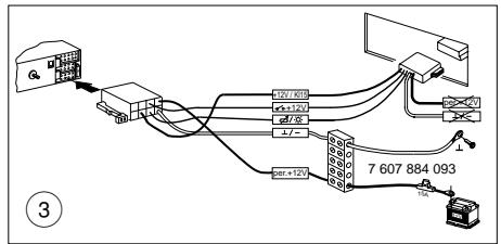
Connection
GB
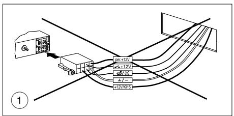
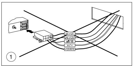
① In order to take advantage of the full car radio output and to avoid incorrect electrical connections with ISO plugs in the vehicle, it is advisable not to use the vehicle-specific positive/negative connection for this car radio.
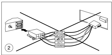
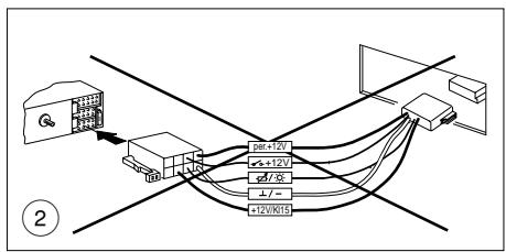
② You can avoid making incorrect connections by using the vehicle-specific Blaupunkt adapter wiring, but!
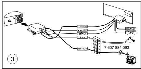
③ Due to the limited cross-section of the wiring in the vehicle, it is necessary to use the connection cable 7 607 884 093 in addition to the vehicle-specific Blaupunkt adapter wiring for the positive/negative connection.
Be sure to observe Fig. 4, 5
Advantage: The vehicle's wiring system is not damaged.
Observation for pre-fitted vehicles, e.g. Audi/VW, Mercedes, Ford, Honda, Porsche
If the vehicle has already been equipped with a 10 A fuse for radio connection at the factory, then the vehicle-specific adapter cable is required for hook-up only.
Advantage: The vehicle's wiring system is not damaged.
Positive connection
Cut the permanent +12 volts line from the vehicle-specific Blaupunkt adapter wiring, join it with connection cable 7 607 884 093 and connect it directly to the positive terminal of the battery.
Negative connection
Do not connect the negative line to the negative terminal of the battery. Cut the negative line from the vehicle-specific Blaupunkt adapter wiring, join it with connection cable 7 607 884 093 and lay the negative line to a suitable ground, such as a chassis screw, the chassis itself or corresponding grounds (do not roll up the wiring).
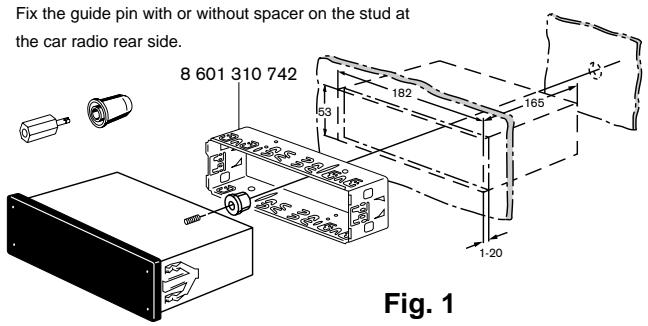
Preparing for the installation of the car radio
The car radio is designed to be installed in the car radio compartment provided by the vehicle manufacturer. Open the car radio compartment (remove the shelf or panel by unclipping it) or adjust the size of the car radio compartment to measure 182 x 53 mm.
For vehicles with deviating installation compartments, Blaupunkt offers installation kits for 50 mm radio units for the most popular vehicle models.
Check the installation situation in the vehicle and, if necessary, use one of the special installation kits for specific vehicle models,
e.g. Audi A4/A6/A8: 7 608 021 473
Note:
The mounting bracket included with this car radio is designed for installation in vehicles with a standard DIN installation compartment measuring 182 x 53 mm, 165 installation depth and an instrument panel thickness of approximately 1 to 20 mm in the area of the tab fasteners, see Fig. 1.
Reach behind the car radio compartment and check to see which tab fasteners can be bent for the mounting bracket.
Note: Try to be sure to bend all of the tabs.
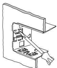
Place the mounting bracket in the compartment and bend over the tabs with the help of a screwdriver, see Fig. 1, 2.
Connection, see page 4 or 5 or 6
Connection instructions.... Fig. 4
Positive/negative connection with vehicle-specific adapter cable ...... Fig. 5
Positive/negative connection with connection line
7 607 884 093 ...... Fig. 5a
Equalizer or amplifier connection, (CINCH) ...... Fig. 6
Do not connect the control wire to terminal 15 (+12 V switched) or terminal 30 (permanent +12 V), maximum load < 150 mA.
Connection of 4 loudspeakers (4/35 W) ...... Fig. 7
LF = left front, RF = right front, LR = left rear, RR = right rear.
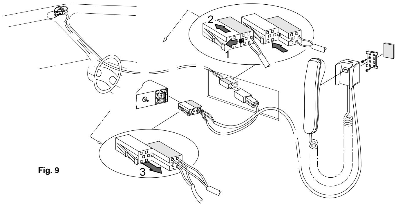
Connection of free speech microphon ...... Fig. 8
Connection of hand set ...... Fig. 9
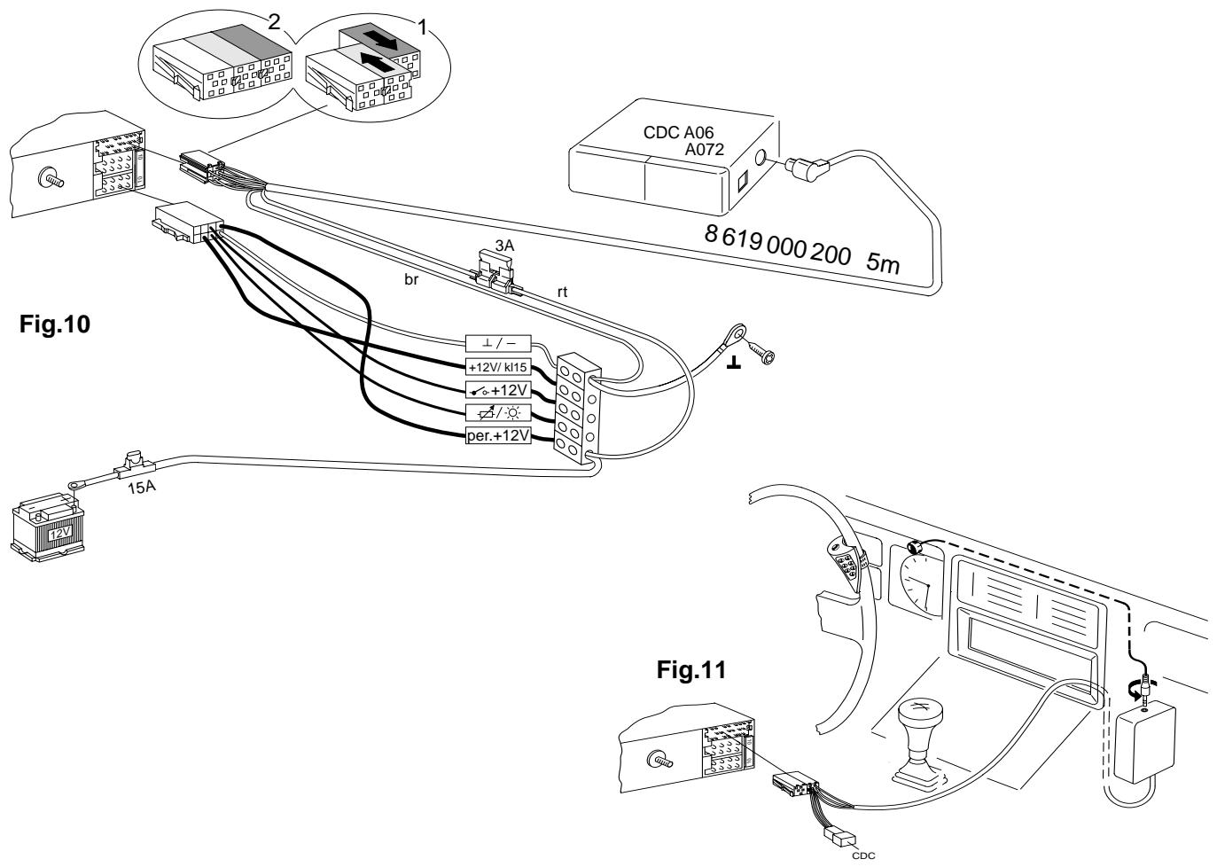
CD player connection CDC-A06 / 072 ...... Fig. 10
Connection of IR remote control RCT-07 ...... Fig. 11
Use the connection cable attached to the remote control.
If necessary, also use cables 7 607 647 093 and 7 607 648 000.
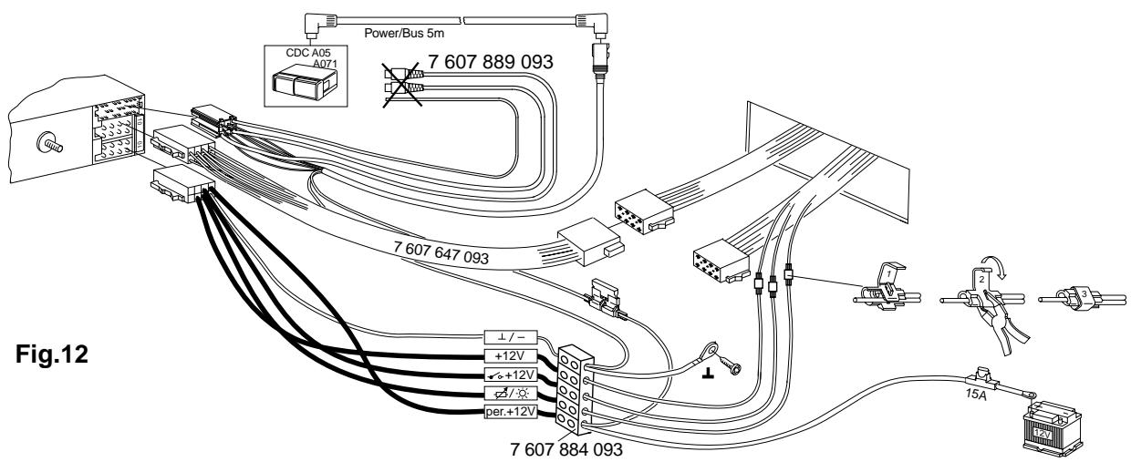
CD player connection CDC-A05 / 071 ...... Fig. 12
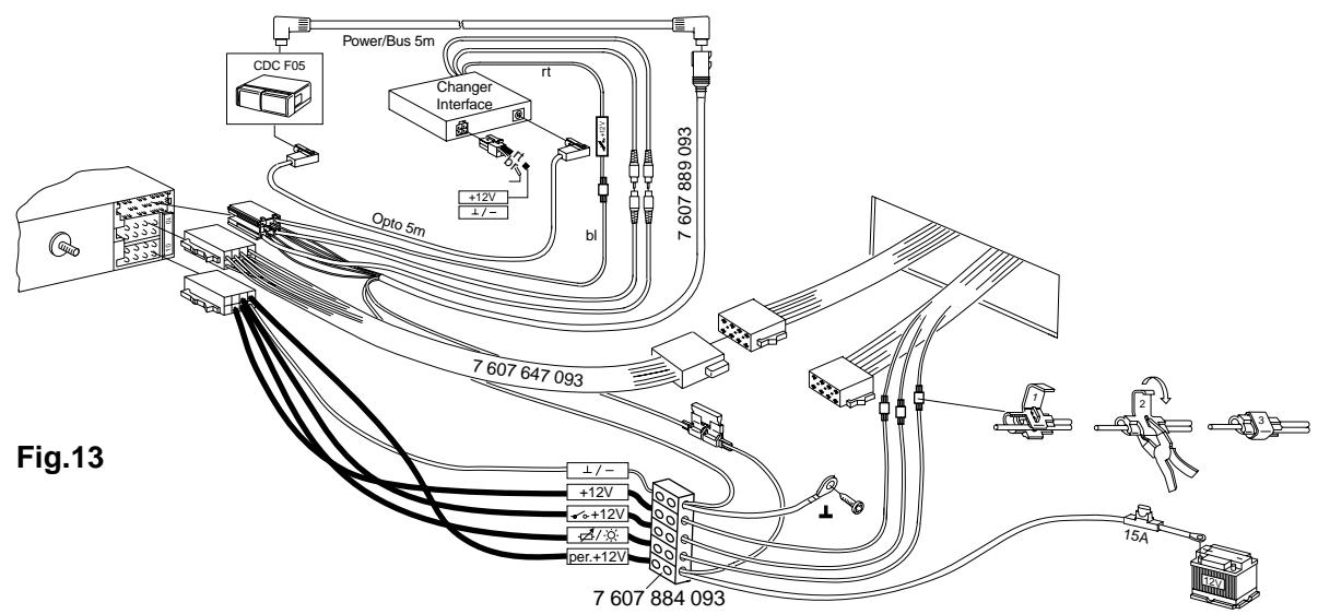
CD player connection CDC-F05 ...... Fig. 13
Connection in vehicles with QuickOut or remote control
In vehicles equipped with a QuickOut (currently Opel), the QuickOut unit must be removed and the adapter cable used. A car radio remote control (e.g. on steering wheel), amplifier or CD changer installed by the car manufacturer is not operable in combination with a Blaupunkt car radio. Installing the car radio
Place the car radio in the front of the mounting bracket and push it in until the side springs snap into position on the left and the right (you will hear an audible click).
Removing the car radio
Insert the handles into the holes in the panel on the left and right of the radio and push them in until you hear a distinct click (unlocks side springs).
Pull the unit out using both handles, see Fig. 3
Note: Handles which have snapped into place can only be removed after you have pulled the radio out of the compartment.
DNC (masking of driving noises)
For a description of the equaliser setting and the DNC calibration process (masking of driving noises) please refer to the owner's manual. This information is subject to change without notice!
Illustrations
8 622 400 963
natural_image
Technical line drawing of a mechanical assembly with no visible text or symbols
Fig. 2

Fig. 3
Connection notes, fig. 4
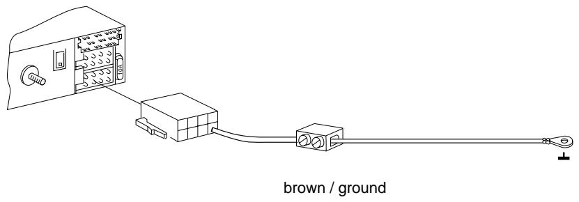
Negative connection (Ground)
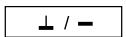
Do not connect the negative line to the negative terminal of the battery. Lay the negative line to a suitable ground, such as a chassis screw or the chassis itself. Cut the ground line as necessary. Then strip the insulation and attach a cable lug (solder if necessary). Remove the paint of the ground contact surface and treat with graphite grease (important for a good ground connection). Screw ground line.
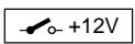
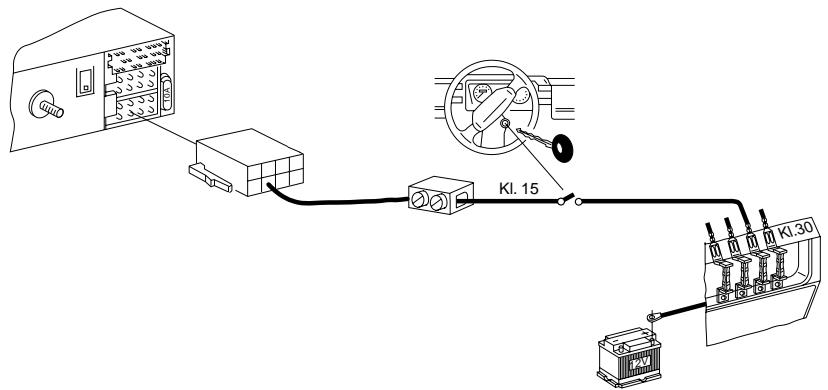
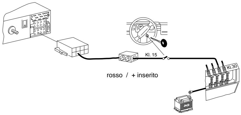
Positive connection +12 V switched (ACC +12 V)
(Ignition)

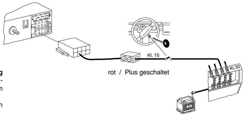
When connecting the positive line to terminal 15 of the fuse box (+12 V via ignition) behind the fuse, it will be possible to turn the system on and off via the ignition. Also, the unit will automatically switch off after one hour of playback time to avoid that the battery goes flat. This hour logic will not be activated when connecting the permanent +12 V line (terminal 30).
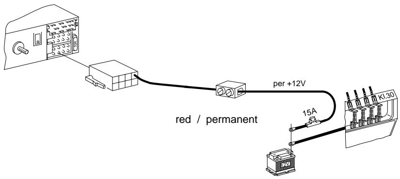
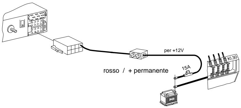
Permanent +12 V connection
(Battery +12 V)
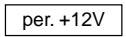
Do not connect the vehicle's positive line!
Lay the red positive wire with a 2.5 mm2 cross section to the battery (do not route close to vehicle harnesses). Connect the fuse box to protect the positive line and hook up to the positive terminal of the battery. If necessary, drill a hole into the splash wall and use a cable duct as required. When mounting the anti-interference choke coil, wrap in foamed plastic.
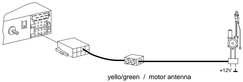
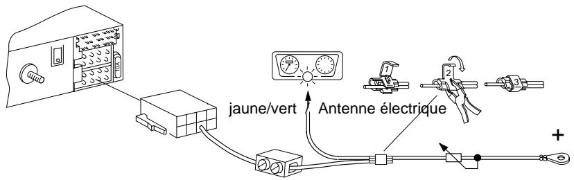
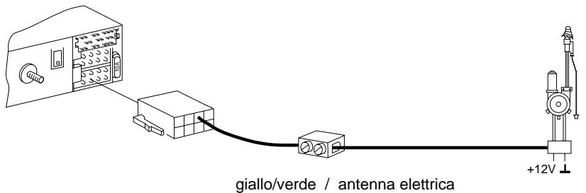
Control wire (Power Antenna +)
The control wire is the switched positive output for external pieces of equipment such as a power antenna, maximum load < 150 mA.
Do not connect the control wire to terminal 15 (+12 V switched) or terminal 30 (permanent +12 V).
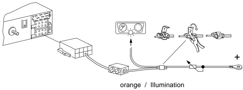
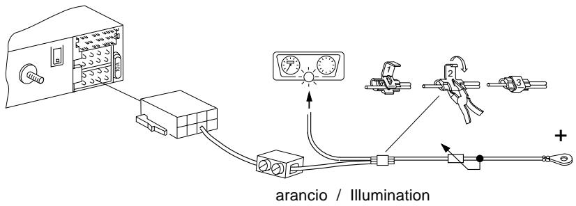
Lighting connection (Illumination)
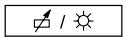
Lighting connection for vehicles with adjustable dashboard lighting (plus-controlled).
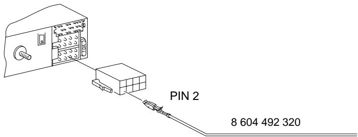
External Alarm
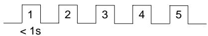
only by ignition off
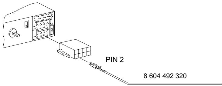
connection to pin 2 only via time-delayed relay maximum load < 100 mA. Duration = 5 ringing tones

natural_image
Technical line drawing of a mechanical device with internal components (no text or symbols)
Fig. 2

Fig. 3
Conseils de raccordement, fig. 4
natural_image
Pure electrical circuit lines without any symbols
marron / Masse
natural_image
Technical line drawing of a mechanical assembly with no visible text or symbols
Fig. 2
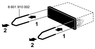
Fig. 3

natural_image
Pure electrical circuit lines without any symbols
gul/grön / elektr.antenn
orange / Illumination
natural_image
Technical line drawing of a mechanical assembly with internal components (no text or symbols)
Fig. 2

Fig. 3
naranjo / Illumination

flowchart
graph TD
    A["Warehouse"] --> B["Truck"]
    B --> C["Server"]
    C --> D["Distance 1:0"]
    C --> E["Distance 2:1"]
    C --> F["Distance 3:2"]
    C --> G["Distance 4:3"]
    C --> H["Distance 5:4"]
    C --> I["Distance 6:5"]
    C --> J["Distance 7:6"]
    C --> K["Distance 8:7"]
    C --> L["Distance 9:8"]
    C --> M["Distance 10:9"]
    C --> N["Distance 11:10"]
flowchart
graph TD
    A["Device 1"] --> B["Switch"]
    C["Device 2"] --> B
    D["Device 3"] --> B
    E["Device 4"] --> B
    F["Device 5"] --> B
    G["Device 6"] --> B
    H["Device 7"] --> B
    I["Device 8"] --> B
    J["Device 9"] --> B
    K["Device 10"] --> B
    L["Device 11"] --> B
    M["Device 12"] --> B
    N["Device 13"] --> B
    O["Device 14"] --> B
    P["Device 15"] --> B
    Q["Device 16"] --> B
    R["Device 17"] --> B
    S["Device 18"] --> B
    T["Device 19"] --> B
    U["Device 20"] --> B
    V["Device 21"] --> B
    W["Device 22"] --> B
    X["Device 23"] --> B
    Y["Device 24"] --> B
    Z["Device 25"] --> B
    AA["Device 26"] --> B
    AB["Device 27"] --> B
    AC["Device 28"] --> B
    AD["Device 29"] --> B
    AE["Device 30"] --> B
    AF["Device 31"] --> B
    AG["Device 32"] --> B
    AH["Device 33"] --> B
    AI["Device 34"] --> B
    AJ["Device 35"] --> B
    AK["Device 36"] --> B
    AL["Device 37"] --> B
    AM["Device 38"] --> B
    AN["Device 39"] --> B
    AO["Device 40"] --> B
    AP["Device 41"] --> B
    AQ["Device 42"] --> B
    AR["Device 43"] --> B
    AS["Device 44"] --> B
    AT["Device 45"] --> B
    AU["Device 46"] --> B
    AV["Device 47"] --> B
    AW["Device 48"] --> B
    AX["Device 49"] --> B
    AY["Device 50"] --> B
flowchart
graph TD
    A["Device"] --> B["Port 1"]
    B --> C["Port 2"]
    C --> D["Port 3"]
    D --> E["Port 4"]
    E --> F["Port 5"]
    F --> G["Port 6"]
    G --> H["Port 7"]
    H --> I["Port 8"]
    I --> J["Port 9"]
    J --> K["Port 10"]
    K --> L["Port 11"]
    L --> M["Port 12"]
    M --> N["Port 13"]
    N --> O["Port 14"]
    O --> P["Port 15"]
    P --> Q["Port 16"]
    Q --> R["Port 17"]
    R --> S["Port 18"]
    S --> T["Port 19"]
    T --> U["Port 20"]
    U --> V["Port 21"]
    V --> W["Port 22"]
    W --> X["Port 23"]
    X --> Y["Port 24"]
    Y --> Z["Port 25"]
    Z --> AA["Port 26"]
    AA --> AB["Port 27"]
    AB --> AC["Port 28"]
    AC --> AD["Port 29"]
    AD --> AE["Port 30"]
    AE --> AF["Port 31"]
    AF --> AG["Port 32"]
    AG --> AH["Port 33"]
    AH --> AI["Port 34"]
    AI --> AJ["Port 35"]
    AJ --> AK["Port 36"]
    AK --> AL["Port 37"]
    AL --> AM["Port 38"]
    AM --> AN["Port 39"]
    AN --> AO["Port 40"]
    AO --> AP["Port 41"]
    AP --> AQ["Port 42"]
    AQ --> AR["Port 43"]
    AR --> AS["Port 44"]
    AS --> AT["Port 45"]
    AT --> AU["Port 46"]
    AU --> AV["Port 47"]
    AV --> AW["Port 48"]
    AW --> AX["Port 49"]
    AX --> AY["Port 50"]
P
Ligação
natural_image
Technical line drawing of a mechanical assembly with no visible text or symbols
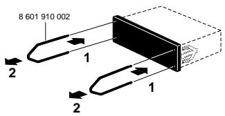
Fig. 3
Fig. 2
natural_image
Line drawing of an electronic device with a connector and cable, no text or symbols present
Castanho / Massa

natural_image
Pure electrical circuit lines without any symbols
orange / Illumination