
BM 2006 - Telephone RCF - Free user manual and instructions
Find the device manual for free BM 2006 RCF in PDF.


| Product Type | Cordless Phone (DECT) |
| Brand | RCF |
| Model | BM 2006 |
| Dimensions (Base) | Approx. 12 x 8 x 8 cm (4.7 x 3.1 x 3.1 in) |
| Dimensions (Handset) | Approx. 16 x 5 x 2.5 cm (6.3 x 2.0 x 1.0 in) |
| Weight (Handset) | Approx. 130 g (4.6 oz) |
| Power Supply | Rechargeable NiMH battery (1.2V, 600mAh) and AC adapter (230V, 50Hz) |
| Standby Time | Up to 100 hours |
| Talk Time | Up to 10 hours |
| Range | Up to 50 m indoors, up to 300 m outdoors |
| Display | Backlit LCD, 2-line display |
| Keypad | Illuminated numeric keypad with additional function keys |
| Phonebook | Up to 100 entries |
| Caller ID | Supported (requires network service) |
| Redial | Last 10 numbers redial |
| Ringer | Adjustable volume, 5 melodies |
| Mute | Mute function during call |
| Cleaning | Use a soft, dry cloth; avoid liquids and abrasives |
| Safety | Keep away from water and heat sources; use only specified batteries |
| Spare Parts | Battery pack (NiMH), AC adapter, charging cradle |
| Repairability | Contact authorized service center for repairs |
| General Information | Intended for indoor use only; complies with relevant EU directives |
Frequently Asked Questions - BM 2006 RCF
User questions about BM 2006 RCF
0 question about this device. Answer the ones you know or ask your own.
Ask a new question about this device
Download the instructions for your Telephone in PDF format for free! Find your manual BM 2006 - RCF and take your electronic device back in hand. On this page are published all the documents necessary for the use of your device. BM 2006 by RCF.
USER MANUAL BM 2006 RCF
USER MANUAL MANUALE D'USO
BM 2006
- ZM 2000 system desk-top paging microphone
SAFETY PRECAUTIONS 3
DESCRIPTION 4
INSTALLATION 7
SETTINGS 8
USE | 11
SPECIFICATIONS | 12
ITALIANO
AVVERTENZE PER LA SICUREZZA 13
DESCRIZIONE 14
INSTALLAZIONE | 17
IMPOSTAZIONI 18
UTILIZZO | 21
DATI TECNICI 22
IMPORTANT NOTES
Before connecting and using this paging microphone, please read this instruction manual carefully and keep it on hand for future reference. The manual is to be considered an integral part of this product and must accompany it when changing ownership as a reference for correct installation and use as well as for the safety precautions.
RCF S.p.A. will not assume any responsibility for the incorrect installation and / or use of this product.
SAFETY PRECAUTIONS
-
All the precautions, in particular the safety ones, must be read with special attention, as they provide important information.
-
Make sure all connections have been made correctly before switching all devices on. Do not connect / disconnect the paging microphone when the system is operating.
-
Protect paging microphone cables from damage and assure they are positioned where these cannot be stepped on or crushed by objects.
-
Do not put the paging microphone into water (or another liquid), do not throw it.
-
Never attempt to carry out any operations, modifications or repairs. If the paging microphone does not work properly, contact your authorized service centre.
-
Should the paging microphone emit any strange odour or even smoke, turn the sound system off immediately and disconnect it.
-
RCF S.p.A. strongly recommends the sound system installation is only made by professional qualified installers (or specialised firms), who can certify it according to the regulations in force. The entire audio system must comply with the current standards and regulations regarding electrical systems.
-
Mechanical and electrical factors need to be considered when installing a professional audio system (in addition to those which are strictly acoustic, such as sound pressure, angles of coverage, frequency response, etc.).
-
Do not point the microphone at near loudspeakers, in order to avoid feedback.
-
Hearing loss
Exposure to high sound levels can cause permanent hearing loss. The acoustic pressure level that leads to hearing loss is different from person to person and depends on the duration of exposure.
To prevent potentially dangerous exposure to high levels of acoustic pressure, anyone who is exposed to these levels should use adequate protection devices. When a transducer capable of producing high sound levels is being used, it is therefore necessary to wear ear plugs or protective earphones.
-
To prevent inductive effects from causing hum, noise and a bad system operating, paging microphone cables should not be laid together with other electric cables (mains) and loudspeaker lines.
-
Keep the paging microphone far from any excessive heat source.
-
Do not use solvents, alcohol, benzene or other volatile substances for cleaning the external parts. Just use a dry cloth.
IMPORTANT NOTES

SAFETY PRECAUTIONS
RCF S.P.A. THANKS YOU FOR PURCHASING THIS PRODUCT, WHICH HAS BEEN DESIGNED TO GUARANTEE RELIABILITY AND HIGH PERFORMANCES.
DESCRIPTION

BM 2006 are 6-zone paging microphones designed for the ZM 2000 system. Up to six BM 2006 can be daisy-chained to a ZM 2124 / ZM 2100 main unit.
It is possible to link up to four BE 2012 additional 12-zone keyboards to every BM 2006, in order to reach the maximum system capability of 54 zones when one ore more ZE 2200 expanders are used.
MAIN FEATURES:
- 6 zone / zone group buttons
- 'All Call' button
- 'PTT' button (momentary microphone activation for short announcements)
- 'Lock' button (as 'PTT', but operating as a toggle for long announcements)
- Flexible gooseneck with an electret microphone capsule
- Balanced input / output on RJ 45 ports (CAT 5 cable)
- Priority mode setting.
MAIN FEATURES
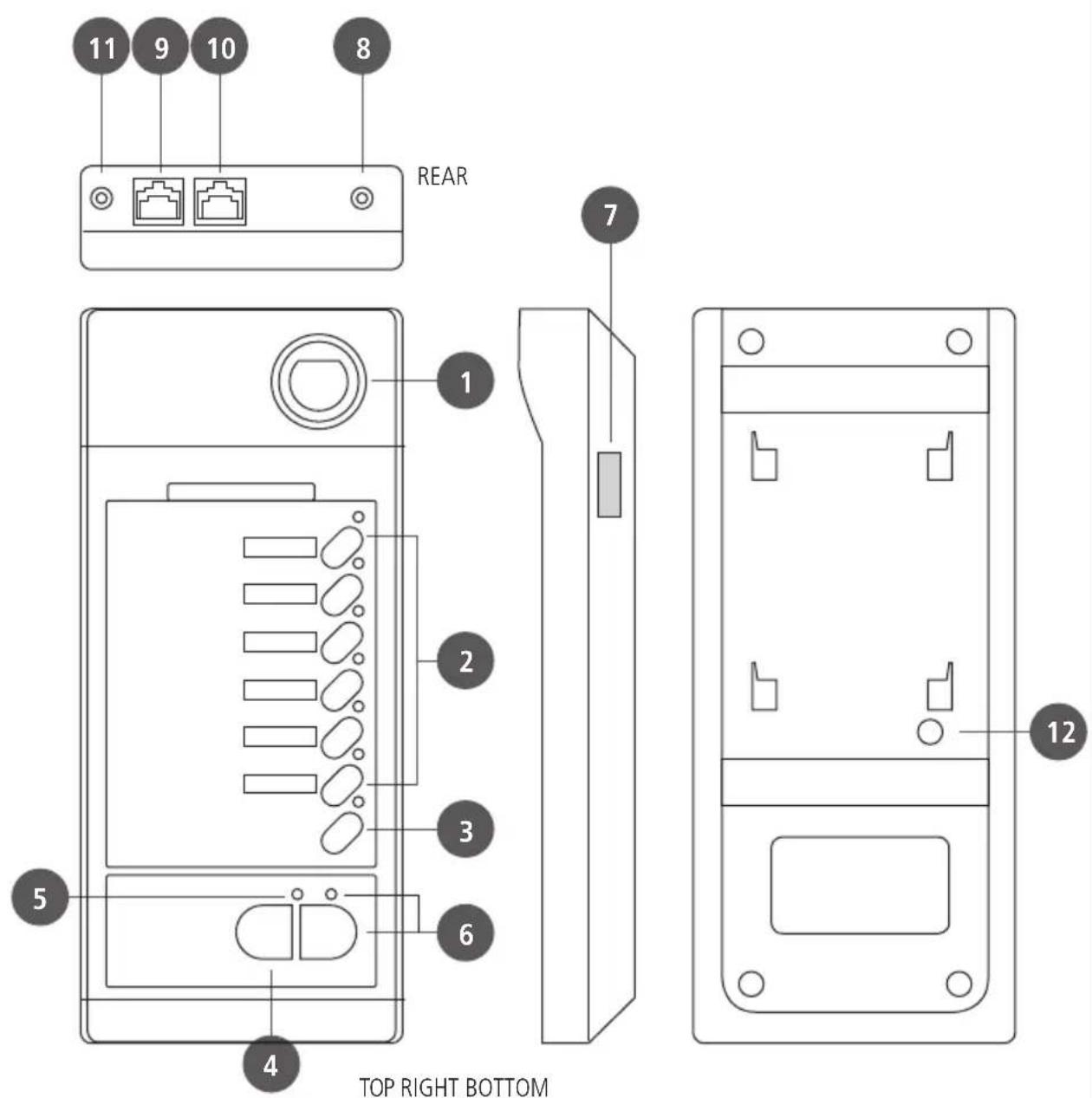
1 Gooseneck with electret microphone.
2 Six zone buttons with LEDs. Press one or more buttons to select and engage the zones to be paged. LEDs (when lit) indicate which zones are selected for paging.
To select a zone group (if previously set, see page 11 'ZONE GROUPS'), press and hold the chosen button for at least 3 seconds.
The selected zone will be activated when pressing either the PTT or the TALK button.
3 ALL CALL button with LED Press the 'All Call' button to select all zones (its respective LED lights up).
All zones will be activated when pressing either the PTT or the TALK button (all zone LEDs light up).
4 PTT button (push-button to be held, mainly indicated for short announcements)
Select zones, then press and hold the PTT button to talk.
If no other paging microphone with higher priority engages the line (or the EMERGENCY is in progress), the chime will be played and then the microphone will get open.
In case of any event in progress with higher priority (the TALK LED 5 will be flashing after pressing the PTT button), it will not be possible to page the selected zones until the line is not busy.
After the announcement, release the PTT button; all selected zone LEDs light off.
If no zone has been selected, press and hold the PTT button to page (again) the same zone / group selected in the previous call.
5 TALK LED
LED steady lit (green): the microphone is open.
LED flashing (amber): the line is busy.
6 LOCK button (toggle switch) with LED
Select zones, then press the LOCK button to talk.
If no other paging microphone with higher priority engages the line (or the EMERGENCY is in progress), the chime will be played and then the microphone will get open.
In case of any event in progress with higher priority (the TALK LED 5
will be flashing after pressing the PTT button), it will not be possible to page the selected zones until the line is not busy.
After the announcement, press the LOCK button again; all selected zone LEDs light off.
7 Connector to link the first BE 2012 additional keyboard.
8 Output level trimmer
If necessary, use a small screw driver to adjust the paging microphone output level.
9 Input (RJ 45 port)
Port to link the next BM 2006 paging microphone (through CAT5 cable).
The system can have max. six BM 2006 paging microphones.
10 Output (RJ 45 port)
Port to link either the previous BM 2006 paging microphone or the ZM 2124 / ZM 2100 main unit (through CAT5 cable).
11 DC power supply input
Jack socket for the connection of an optional 24 V dc adapter.
12 Chime level control
If necessary, use a small screw driver to adjust the chime level.
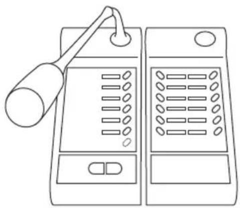
If available, link all BE 2012 additional 12-zone keyboards (max. 4 per each BM 2006), by connecting all flat cables (see the BE 2012 manual) to the lateral ports (7 on BM 2006). Use metal brackets to fix BE 2012 keyboards.
natural_image
Line drawing of two electronic devices with a lamp and control panel (no text or symbols)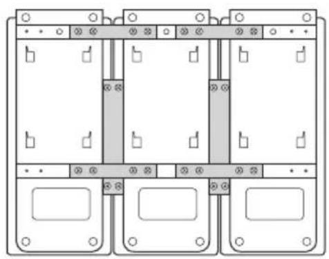
natural_image
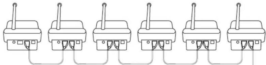
Pure electrical circuit lines without any symbolsConnect all BM 2006 paging microphones (daisy-chained through CAT5 cable), as according to the following figure:
natural_image
Six identical electrical connectors with wires connected in a row (no text or symbols visible)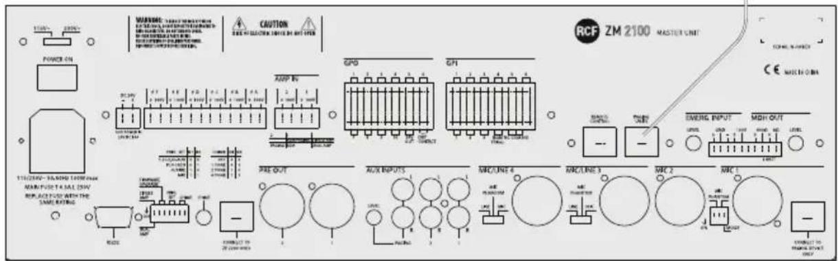
The first BM 2006 needs to be linked to the ZM 2124 / ZM 2100 PAGING UNITS port.
When using long cables or additional BE 2012 keyboards, it is necessary to connect additional 24 V dc adapters to BM 2006 paging microphones.
Turn the system on and set all paging microphones (see the next 'Settings' manual section).
IP ADDRESS
Each BM 2006 paging microphone needs to be set to its unique digital address (there cannot be two or more BM 2006 having the same ID number).
-
Press and hold (at least 3 seconds) both the PTT 4 and zone 6 buttons 2, then both the TALK LED 5 and the zone 6 LED will flash.
-
Press the zone 6 button to get the sequential change of the ID address according to the following table:
IP ADDRESS
| ID ADDRESS | ZONE LEDs | |||
| Zone 1 Zone 2 Zone 3 Zone 4 | ||||
| 1 | ON | |||
| 2 | ON | |||
| 3 | ON | ON | ||
| 4 | ON | |||
| 5 | ON | ON | ||
| 6 | ON | ON | ||
| 7* | ON | ON | ||
| 8* | ON | |||
* ID addresses 7 and 8 are currently not used.
- Press the PTT 4 button to exit.
MIC SENSITIVITY
It is possible to adjust the microphone sensitivity.
-
Press and hold (at least 3 seconds) both the PTT 4 and zone 5 buttons 2, then both the TALK LED 5 and the zone 5 LED will flash.
-
Press the zone 5 button to get the sequential change (6 steps) of the microphone sensitivity according to the following table:
MIC SENSITIVITY
| MIC SENSITIVITY | ZONE LEDs | ||
| Zone 1 Zone 2 Zone 3 | |||
| Minimum | ON ⚙ | ||
| ↓ | ON ⚙ | ||
| ↓ | ON ⚙N | ⋯ | |
| ↓ | ON ⚙ | ||
| ↓ | ON ⚙N | ⋯ | |
| Maximum | ON ⚙ | ON ⚙ | |
- Press the PTT 4 button to exit.
PRIORITY
The priority mode can be chosen among 4 different options.
-
Press and hold (at least 3 seconds) both the PTT 4 and zone 4 buttons 2, then both the TALK LED 5 and the zone 4 LED will flash.
-
Press the zone 4 button to get the sequential change of priority mode according to the following table:
PRIORITY
| PRIORITY MODE | ZONE LEDs | ||
| Zone 1 Zone 2 Zone 3 | |||
| Graduated: paging mic.1 > 2, 2 > 3, 3 > 4 | ON | ||
| Paging microphones work on a first-come-first-served basis | ON | ||
| A new announcement overrides the previous still in progress | ON | ON | |
| All paging microphones have the same priority level | ON | ||
- Press the PTT 4 button to exit.
CHIME
Chime tone setting.
- Press and hold (at least 3 seconds) both the PTT ④ and zone 3 buttons ②, then both the TALK LED ⑤ and the zone 3 LED will flash.
-
- Press the zone 3 button to get the sequential change of the chime mode according to the following table:
| CHIME MODE | ZONE LEDs | |
| Zone 1 Zone 2 | ||
| OFF | ||
| CHIME 1 | ON ⚙️ | |
| CHIME 2 | ON ⚙️ | |
| CHIME 3 | ON ⚙️ | ON ⚙️ |
CHIME
- Press the PTT 4 button to exit.
SPEECH FILTER
It is possible to set on/off the microphone high-pass filter (cutoff frequency: 315 Hz, slope: 6 dB / octave). The high-pass filter may help increase the speech intelligibility in acoustically critical areas (for instance, due to long reverberation time).
- Press and hold (at least 3 seconds) both the PTT ④ and zone 2 buttons ②, then both the TALK LED ⑤ and the zone 2 LED will flash.
- Press the zone 2 button to turn on/off the speech filter:
| SPEECH FILTER ZONE 1 LED | |
| ON | |
| OFF | ON ⚙️ |
- Press the PTT 4 button to exit.
SPEECH FILTER
ZONE GROUPS
It is possible to store some zones to a group, which can be assigned to a single BM 2006 button (max. 6 groups, it is not possible to store zone groups to BE 2012 buttons).
- Press and hold (at least 3 seconds) both the PTT buttons ②, then all zone LEDs will flash.
4 and zone 1 - Select (press) a zone button where to store the group.
- While all LEDs are flashing, select the zones to be added to the group by pressing their respective buttons (in each selected zone, the LED is now steady lit).
- Press the PTT ④ button to confirm and exit.
ZONE GROUPS
USE

- Before turning the system on, connect all BM 2006 paging microphones and BE 2012 keyboards (if available) according to the 'Installation' manual section.
- Turn the system on and (for every BM 2006 paging microphone) set the proper IP address, mic sensitivity, priority, chime, speech filter and zone groups.
- Select zones to be paged; all selected zone LEDs light up. To select a zone group, press and hold the chosen zone button for at least 3 seconds.
- Press and hold the PTT button ④ or press the LOCK button ⑥ to talk. If no other paging microphone with higher priority engages the line (or the EMERGENCY is in progress), the chime will be played and then the microphone will get open. In case of any event in progress with higher priority, it will not be possible to page the selected zones until the line is not busy.
TALK LED 5 steady lit (green): the microphone is open.
TALK LED 5 flashing (amber): the line is busy.
- After the announcement, release the PTT button (if held) or press the LOCK button again; all selected zone LEDs light off.
SPECIFICATIONS

Operating voltage
Max. current draw
24 V dc
50 mA (BM 2006 only)
130 mA (with a single BE 2012 keyboard)
210 mA (with two BE 2012 keyboards)
290 mA (with three BE 2012 keyboards)
370 mA (with four BE 2012 keyboards)
Max. audio output level
Frequency response
Speech filter
1 V (RMS)
100 Hz ÷ 15 kHz
high-pass, cutoff: 315 Hz, slope: 6 dB / octave
Dimensions (w, h, d)
Net weight
108 mm, 55 mm, 240 mm (BM 2006 only)
1 kg (BM 2006 only)
IMPORTANTE
natural_image
Line drawing of two electronic devices with a lamp and control panel (no text or symbols)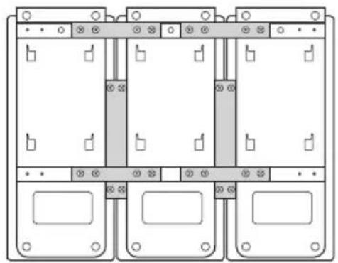
natural_image
Pure electrical circuit lines without any symbolsnatural_image
Six identical electrical connectors with wires connected in a row (no text or symbols visible)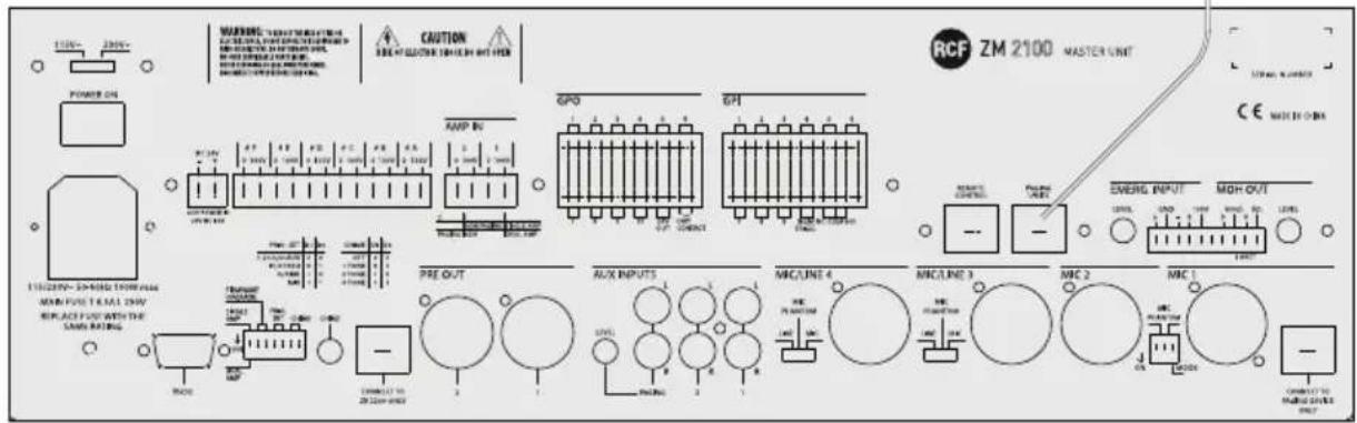
Except possible errors and omissions.
RCF S.p.A. reserves the right to make modifications without prior notice.
www.rcf.it
RCF S.p.A. Italy
Brand : RCF
Model : BM 2006
Category : Telephone