
IN 9000 - Telephone RCF - Free user manual and instructions
Find the device manual for free IN 9000 RCF in PDF.

| Product Type | Cordless DECT Phone |
| Brand | RCF |
| Model | IN 9000 |
| Handset Dimensions | 170 x 50 x 30 mm |
| Base Station Dimensions | 130 x 100 x 50 mm |
| Handset Weight | 150 g |
| Base Station Weight | 200 g |
| Power Supply | AC/DC adapter 6V 500mA |
| Battery Type | NiMH 2.4V 550mAh |
| Standby Time | Up to 100 hours |
| Talk Time | Up to 10 hours |
| Frequency Band | 1.88 to 1.90 GHz (DECT) |
| Range Indoor | Up to 50 meters |
| Range Outdoor | Up to 300 meters |
| Caller ID | Yes |
| Phonebook Capacity | 100 entries |
| Handsfree Speakerphone | Yes |
| Display Type | Backlit LCD |
| Keypad Illumination | Yes |
| Maintenance | Clean with dry soft cloth |
| Safety | Use only supplied power adapter |
| Replacement Parts | Battery pack, charger base |
Frequently Asked Questions - IN 9000 RCF
User questions about IN 9000 RCF
0 question about this device. Answer the ones you know or ask your own.
Ask a new question about this device
Download the instructions for your Telephone in PDF format for free! Find your manual IN 9000 - RCF and take your electronic device back in hand. On this page are published all the documents necessary for the use of your device. IN 9000 by RCF.
USER MANUAL IN 9000 RCF
USER MANUAL MANUALE D'USO
IN 9000
- DXT 9000 SYSTEM INTEGRITY NETWORK EMERGENCY CONSOLE
- CONSOLLE D'EMERGENZA PER L'INTERA RETE DEL SISTEMA DXT 9000
TABLE OF CONTENTS INDICE

ENGLISH
SAFETY PRECAUTIONS
DESCRIPTION
FRONT PANEL AND HANDHELD MICROPHONE
INTERNAL BOARD CONNECTIONS
SYSTEM CONNECTIONS
SPECIFICATIONS
4
5
6
7
9
10
ITALIANO
AVVERTENZEPERLASICUREZZA
DESCRIZIONE
PANNELLO FRONTALE E MICROFONO PALMARE
COLLEGAMENTI ALLA SCHEDA INTERNA DELLA CONSOLLE
COLLEGAMENTI AL SISTEMA
DATI TECNICI
12
13
14
15
17
18
IMPORTANT NOTES
Before connecting and using this console, please read this instruction manual carefully and keep it on hand for future reference. The manual is to be considered an integral part of this product and must accompany it when changing ownership as a reference for correct installation and use as well as for the safety precautions. RCF S.p.A. will not assume any responsibility for the incorrect installation and / or use of this product.
SAFETY PRECAUTIONS
- According to EN 54-16 standard, paging microphones shall be only accessible by persons having a specific responsibility for safety and who are trained and authorized to operate in the following conditions: quiescent, voice alarm, fault warning and disablement.
- All the precautions, in particular the safety ones, must be read with special attention, as they provide important information.
- Make sure all connections have been made correctly before switching all devices on. Do not connect / disconnect this console when the system is operating.
- Protect console cables from damage and assure they are positioned where these cannot be stepped on or crushed by objects.
- Do not put this console into water (or another liquid), do not throw it.
- Never attempt to carry out any operations, modifications or repairs. If the console does not work properly, contact your authorized service centre.
- Should the console emit any strange odour or even smoke, turn the sound system off immediately and disconnect it.
- RCF S.p.A. strongly recommends the sound system installation is only made by professional qualified installers (or specialised firms), who can certify it according to the regulations in force. The entire audio system must comply with the current standards and regulations regarding electrical systems.
- Mechanical and electrical factors need to be considered when installing a professional audio system (in addition to those which are strictly acoustic, such as sound pressure, angles of coverage, frequency response, etc.).
- Do not point the microphone at near loudspeakers, in order to avoid feedback.
- Hearing loss
Exposure to high sound levels can cause permanent hearing loss. The acoustic pressure level that leads to hearing loss is different from person to person and depends on the duration of exposure. To prevent potentially dangerous exposure to high levels of acoustic pressure, anyone who is exposed to these levels should use adequate protection devices.
When a transducer capable of producing high sound levels is being used, it is necessary to wear ear plugs or protective earphones. - To prevent inductive effects from causing hum, noise and a bad system operating, microphone cables should not be laid together with other electric cables (mains) and loudspeaker lines.
- Keep the console far from any excessive heat source.
- Do not use solvents, alcohol, benzene or other volatile substances for cleaning the external parts. Just use a dry cloth.
IMPORTANT NOTES

WARNING:
Any change made by unauthorized personnel to the product and / or the system (in which it is installed and configured, including rack cabinet and wiring) may invalidate the CE marking (certification EN54-16: 2008) and also the product warranty.
RCF S.P.A. THANKS YOU FOR PURCHASING THIS PRODUCT, WHICH HAS BEEN DESIGNED TO GUARANTEE RELIABILITY AND HIGH PERFORMANCES.
DESCRIPTION

IN 9000 is an emergency fireman console designed to be interfaced with the RCF DXT 9000 evacuation system, in order to provide an analogue backup solution for emergency communications, in case of interruption of the main digital connection RCFBUS.
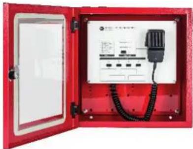
This console is protected by a wall-mounted red metallic box with glass and equipped with a monitored handheld microphone having a momentary 'Push-To-Talk' (PTT) button. The PTT command is also available as front panel button, together with a VU-meter LED bar (microphone signal level) and an 'IN USE' LED.
IN 9000 needs an external 24 ÷ 48 V dc power supply EN54-4 providing at least 20W output power. Moreover, a monitored GPI is provided to report any power supply fault. The audio output can be distributed up to 64 DXT 9000 units and routed to 4 independent lines selectable on the console front panel. A dedicated (optional) RCF OT 3500 audio transformer can be installed on each output line.
MAIN FEATURES
- Monitored fireman's microphone with PTT button.
- The console is protected by a wall-mounted red metallic box with glass.
- Fully analogue connection (in the event of interruption of RCF BUS).
- Output signal can be sent to max. 64 DXT 9000 units over 4 selectable independent lines.
- 2 monitored GPI ('General Purpose Input'): power supply and DXT 9000 fault.
- 1 monitored GPO ('General Purpose Output') to report a console fault to DXT 9000.
- Power supply range 24 ÷ 48 V dc (external 20 W power supply required).
- Front panel fault reporting: general, microphone, command port, power supply, power supply GPI, DXT general, DXT general GPI.
IMPORTANT NOTES
IN 9000 shall be placed in a room with access restricted to authorized personnel only, within a protected area not subjected to conditions that may affect its operation, for example: moisture, salt, water infiltration, extreme temperatures, shocks, etc.
It should be placed at a height from the floor that makes it easily accessible.
Also check the suitability of the wall and the components used for attachment (wall plugs, screws, not supplied by RCF), which must guarantee the system security over time, also considering, for example, the mechanical vibrations normally generated by transducers.
natural_image
Red open electrical control box with wiring and internal components (no visible text or symbols)FRONT PANEL AND HANDHELD MICROPHONE

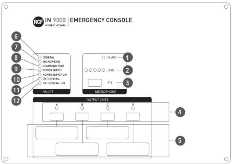
1 IN USE LED When lit: the console is being used.
2 LEVEL LED bar indicating the microphone signal level.
3 PTT ('Push To Talk') button: push and hold down to turn the microphone on and page the areas assigned to the output lines A, B, C, D, previously selected by pushing the respective buttons 4.
4 OUTPUT LINES A-B-C-D buttons with LEDs: push to toggle on/off the respective output lines.
5 The rectangles graphically linked to the OUTPUT LINES A, B, C, and D can be used to add labels aimed at better identifying them.
FAULT LEDs
| LABEL DESCRIPTION | ||
| 6 | GENERAL Console local general fault | |
| 7 | MICROPHONE Console microphone fault | |
| 8 | COMMAND PORT Command port fault (no monitoring 24 V dc) | |
| 9 | POWER SUPPLY External power supply fault (monitored GPI) | |
| 10 | POWER SUPPLY GPI IN 9000 internal fault on its 'Power Supply Fault' GPI | |
| 11 | DXT GENERAL DXT 9000 general fault (monitored GPI) | |
| 12 | DXT GENERAL GPI IN 9000 internal fault on its 'DXT 9000 General Fault' GPI | |
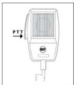
HANDHELD MICROPHONE
The handheld microphone momentary push button has the same function of the front panel PTT button 3.
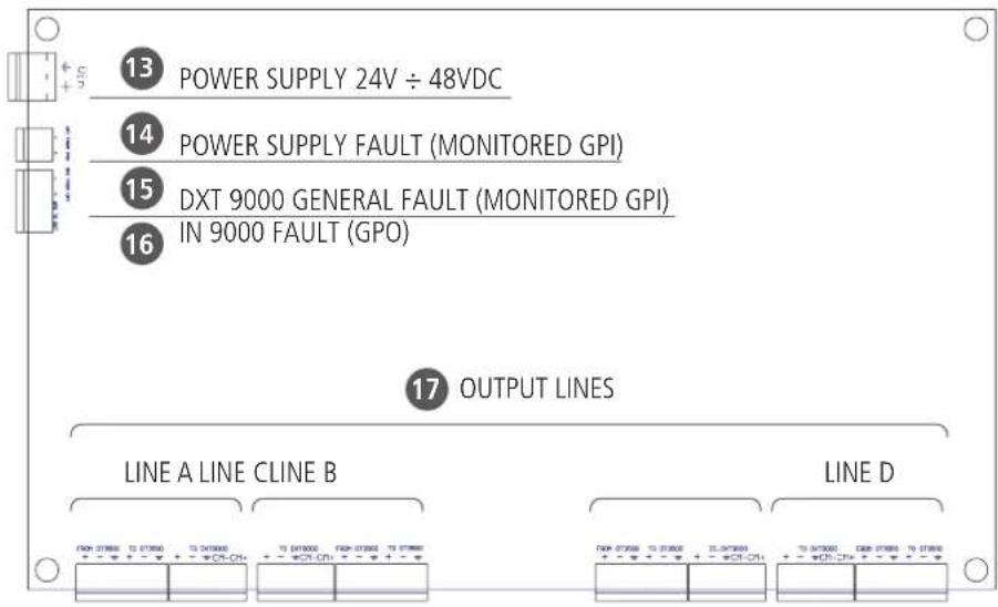
- Connect the IN 9000 POWER SUPPLY INPUT 13 to the external EN 54-4 power supply output (24 ÷ 48 V dc, 20 W). Pay attention to its polarity.
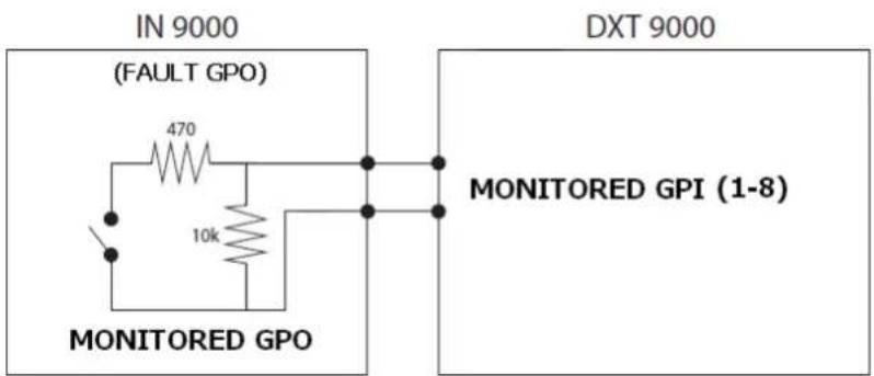
- Connect the IN 9000 'POWER SUPPLY FAULT' MONITORED GPI 14 to the external power supply GPO (for remote fault monitoring).
- Connect a DXT 9000 unit monitored GPO to the IN 9000 'DXT 9000 GENERAL FAULT' MONITORED GPI15.
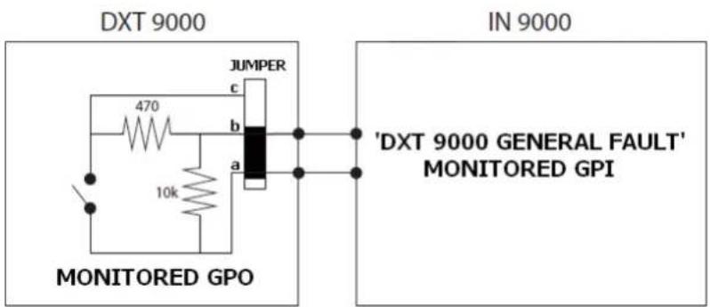
- Connect the 'IN 9000 FAULT' GPO 16 to a DXT 9000 unit monitored GPI (1÷8).
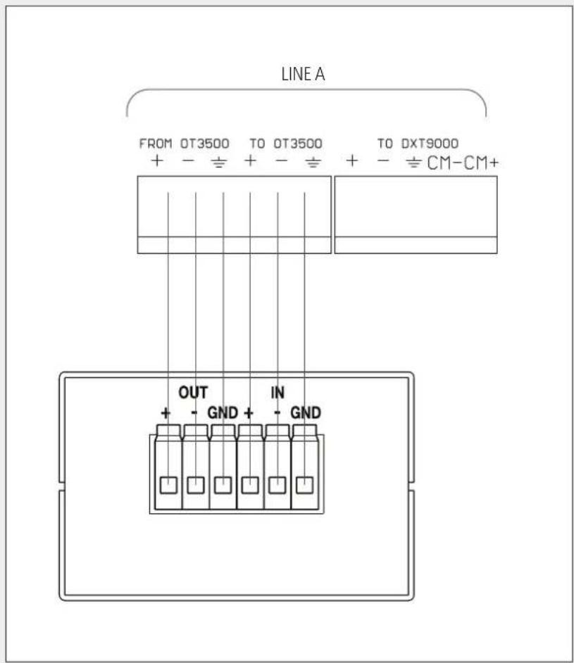
- Connect IN 9000 output lines 17 to FALLBACK inputs of DXT 9000 units, as shown in the following figure (audio: + hot, - cold, ground; command: CM-, CM+)
NOTE: IF OT 3500 TRANSFORMERS ARE NOT REQUIRED ON THE OUTPUT LINES, THE CORRESPONDING FROM / TO CONTACTS SHALL BE SHORTED (FACTORY SETTING).
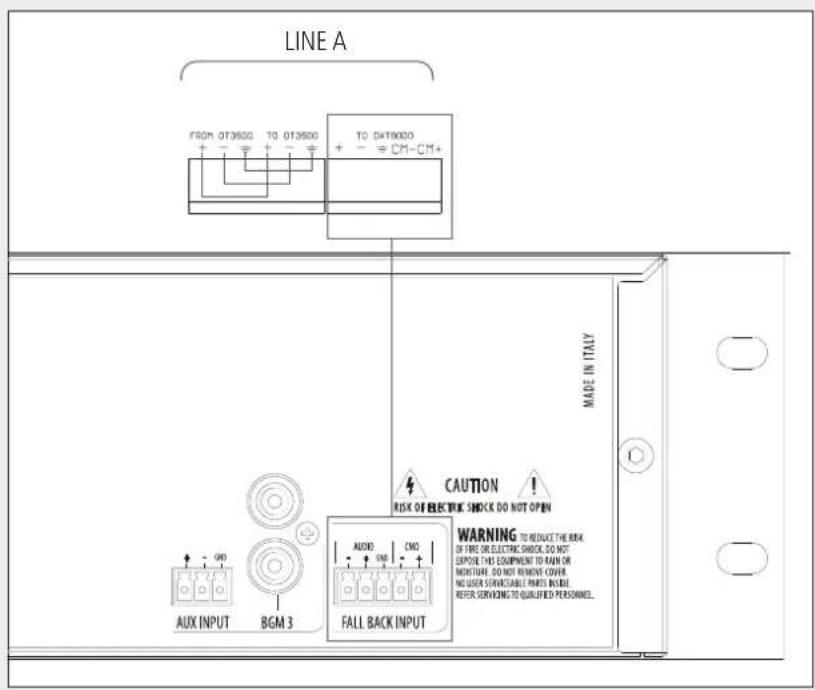
- If an OT 3500 transformer is necessary on an output line due to excessive noise, connect it (pin to pin) as shown in the next figure.
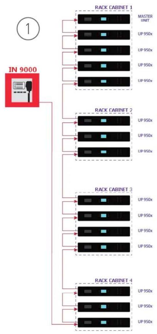
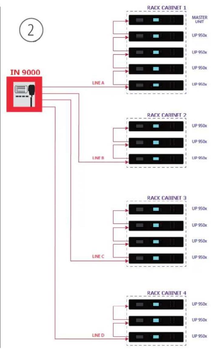
IN 9000 can be connected to several rack cabinets (including DXT 9000 main units and amplifiers), routing its audio output through max. 4 independent lines.
For example, next 2 figures show 2 possible wirings: the former ① is the most simple one (using only one output line), the latter ② is the most complex one (using all the 4 output lines).
Of course, any layout in between is possible, depending on installation requirements.
flowchart
graph TD
    A["IN 9000"] --> B["RACK CABINET 1"]
    A --> C["RACK CABINET 2"]
    A --> D["RACK CABINET 3"]
    A --> E["RACK CABINET 4"]
    B --> F["MASTER UNIT"]
    B --> G["UP 950x"]
    B --> H["UP 950x"]
    B --> I["UP 950x"]
    B --> J["UP 950x"]
    C --> K["MASTER UNIT"]
    C --> L["UP 950x"]
    C --> M["UP 950x"]
    C --> N["UP 950x"]
    C --> O["UP 950x"]
    D --> P["MASTER UNIT"]
    D --> Q["UP 950x"]
    D --> R["UP 950x"]
    D --> S["UP 950x"]
    D --> T["UP 950x"]
    E --> U["MASTER UNIT"]
    E --> V["UP 950x"]
    E --> W["UP 950x"]
    E --> X["UP 950x"]
flowchart
graph TD
    A["IN 9000"] -->|LINE A| B["RACK CABINET 1"]
    A -->|LINE A| C["RACK CABINET 2"]
    A -->|LINE B| D["RACK CABINET 3"]
    A -->|LINE C| E["RACK CABINET 4"]
    A -->|LINE D| F["RACK CABINET 4"]
    B --> G["MASTER UNT"]
    B --> H["UP 950x"]
    B --> I["UP 950x"]
    B --> J["UP 950x"]
    B --> K["UP 950x"]
    C --> L["MASTER UNT"]
    C --> M["UP 950x"]
    C --> N["UP 950x"]
    C --> O["UP 950x"]
    C --> P["UP 950x"]
    D --> Q["MASTER UNT"]
    D --> R["UP 950x"]
    D --> S["UP 950x"]
    D --> T["UP 950x"]
    D --> U["UP 950x"]
    E --> V["MASTER UNT"]
    E --> W["UP 950x"]
    E --> X["UP 950x"]
    E --> Y["UP 950x"]
    E --> Z["UP 950x"]
    F --> AA["MASTER UNT"]
    F --> AB["UP 950x"]
    F --> AC["UP 950x"]
    F --> AD["UP 950x"]
    F --> AE["UP 950x"]
Microphone type: dynamic
Mic. polar patter: omnidirectional
Output impedance: 500 Ω ± 30% (1 kHz)
Microphone sensitivity: -70 dB ± 3 dB (0 dB=1V/μbar, 1 kHz)
Frequency response: 300 Hz ÷ 6 kHz (-3 dB)
Box dimensions: 360 x 360 x 129 mm
Net weight: 7 kg
IMPORTANTE
natural_image
Red open electrical enclosure with internal wiring and control panel (no visible text or symbols)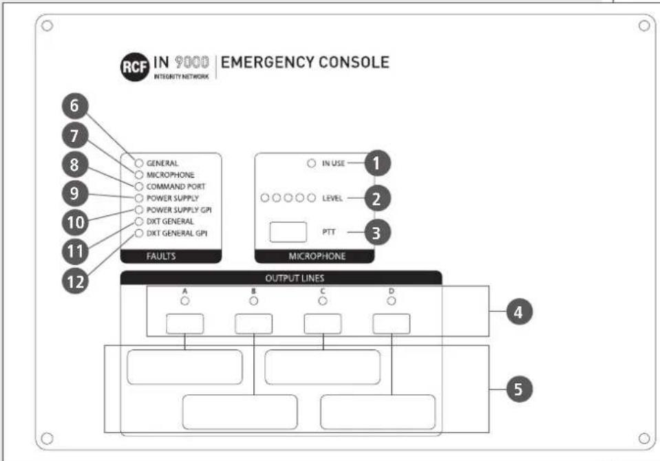
 0068 0068 |
| RCF S.p.A. - Via Raffaello Sanzio 13, 42124 Reggio Emilia, ITALY140068-CPR-002/2014 |
| EN 54-16:2008Voice alarm control and indicating equipment for fire detection and fire alarm systems for buildingsDXT 9000Provided options7.3 Audible warnings7.6.2 Manual silencing of the voice alarm condition7.7.2 Manual reset of the voice alarm condition7.8 Output to fire alarm devices7.9 Voice alarm condition output8.3 Indication of faults related to the transmission path to the CIE9 Disablement condition10 Voice alarm manual control11 Interface to external control device(s)12 Emergency microphone(s)13, 14 Redundant power amplifiersDoP: 008_17Other technical data: see operational manual. |
Except possible errors and omissions.
RCF S.p.A. reserves the right to make modifications without prior notice.
www.rcf.it


Brand : RCF
Model : IN 9000
Category : Telephone