
MQ 80P - Loudspeaker RCF - Free user manual and instructions
Find the device manual for free MQ 80P RCF in PDF.


| Product Type | Passive PA Speaker |
| Brand | RCF |
| Model | MQ 80P |
| Dimensions (HxWxD) | 450 x 280 x 270 mm |
| Weight | 11 kg |
| Power Handling (RMS) | 200 W |
| Impedance | 8 ohms |
| Frequency Response | 65 Hz - 20 kHz |
| Sensitivity (1W/1m) | 95 dB |
| Woofer | 8" (200 mm) |
| Tweeter | 1" (25 mm) compression driver |
| Coverage Angle (HxV) | 90° x 60° |
| Connectors | 2 x Speakon NL4 |
| Enclosure Material | Plywood |
| Finish | Black paint |
| Grille | Perforated steel with acoustic foam |
| Handle | 1 top handle |
| Flying Points | 2 x M10 |
| Maintenance | Clean with dry cloth; avoid moisture |
| Safety | Do not expose to rain; ensure stable mounting |
| Spare Parts | Available from RCF authorized service centers |
Frequently Asked Questions - MQ 80P RCF
User questions about MQ 80P RCF
0 question about this device. Answer the ones you know or ask your own.
Ask a new question about this device
Download the instructions for your Loudspeaker in PDF format for free! Find your manual MQ 80P - RCF and take your electronic device back in hand. On this page are published all the documents necessary for the use of your device. MQ 80P by RCF.
USER MANUAL MQ 80P RCF
Before connecting and using this product, please read this instruction manual carefully and keep it on hand for future reference. The manual is to be considered an integral part of this product and must accompany it when it changes ownership as a reference for correct installation and use as well as for the safety precautions.
RCF S.p.A. will not assume any responsibility for the incorrect installation and / or use of this product.
WARNING: To prevent the risk of fire or electric shock, never expose this loudspeaker to rain or humidity and dust, but the case this has been expressly designed and made to get a suitable IP protection grade (indicated in the product specifications).
SAFETY PRECAUTIONS
-
All the precautions, in particular the safety ones, must be read with special attention, as they provide important information.
-
Loudspeaker lines (amplifier outputs) can have a sufficiently high voltage (i.e. 100 V) to involve a risk of electrocution: never install or connect this loudspeaker when the line is alive.
-
Make sure all connections have been made correctly and the loudspeaker input voltage (in a constant voltage system) or its impedance is suitable for the amplifier output.
-
Protect loudspeaker lines from damage; make sure they are positioned in a way that they cannot be stepped on or crushed by objects.
-
Make sure that no objects or liquids can get into this product, as this may cause a short circuit.
-
Never attempt to carry out any operations, modifications or repairs that are not expressly described in this manual.
Contact your authorized service centre or qualified personnel should any of the following occur:
- the loudspeaker does not function (or works in an anomalous way);
- the cable has been damaged;
- objects or liquids have got into the unit;
-
the loudspeaker has been damaged due to heavy impacts / fire.
-
Should the loudspeaker emit any strange odours or smoke, remove it from the line after having switched the amplifier off.
-
Do not connect this product to any equipment or accessories not foreseen. For suspended installation, only use the dedicated anchoring points and do not try to hang this loudspeaker by using elements that are unsuitable or not specific for this purpose.
Also check the suitability of the support surface to which the product is anchored (wall, ceiling, structure, etc.), and the components used for
IMPORTANT NOTES

WARNING

attachment (screw anchors, screws, brackets not supplied by RCF etc.), which must guarantee the security of the system / installation over time, also considering, for example, the mechanical vibrations normally generated by transducers.
9. RCF S.p.A. strongly recommends this product is only installed by professional qualified installers (or specialised firms) who can ensure a correct installation and certify it according to the regulations in force.
The entire audio system must comply with the current standards and regulations regarding electrical systems.
- There are numerous mechanical and electrical factors to be considered when installing a professional audio system (in addition to those which are strictly acoustic, such as sound pressure, angles of coverage, frequency response, etc.).
11. HEARING LOSS
Exposure to high sound levels can cause permanent hearing loss. The acoustic pressure level that leads to hearing loss is different from person to person and depends on the duration of exposure. To prevent potentially dangerous exposure to high levels of acoustic pressure, anyone who is exposed to these levels should use adequate protection devices. When a transducer capable of producing high sound levels is being used, it is therefore necessary to wear ear plugs or protective earphones.
See the technical specifications in the instruction manual for the maximum sound pressure the loudspeaker is capable of producing.
- To ensure a correct musical reproduction, loudspeaker phase is to be respected (loudspeakers are connected respecting the amplifier polarity). This is important when loudspeakers are installed adjacent one another, for instance, in the same room.
- To prevent inductive effects from causing hum, noise and a bad system working, loudspeaker lines should not be laid together with other electric cables (mains), microphone or line level signal cables connected to amplifier inputs.
- The loudspeaker cable shall have wires with a suitable section (twisted, if possible, to reduce inductive effects due to surrounding electro-magnetic fields) and a sufficient electrical insulation.
OPERATING PRECAUTIONS
- Install this loudspeaker far from any heat source.
- Do not overload this product for extended periods of time.
- Never force the control elements (keys, knobs,etc.).
- Do not use solvents, alcohol, benzene or other volatile substances for cleaning the external parts of this product.
- If the speaker is used in particular cold places, drive it with a low signal for 5-10 minutes before using it at maximum power.
OPERATING PRECAUTIONS
RCF S.P.A. WOULD LIKE TO THANK YOU FOR HAVING PURCHASED THIS PRODUCT, WHICH HAS BEEN DESIGNED TO GUARANTEE RELIABILITY AND HIGH PERFORMANCE.
DESCRIPTION

MQ 80P is a two way horn-loaded speaker system that belongs to MONITOR Q series. Its high quality, high efficiency and compact design make it the ideal solution to get clear voice and music reproduction in mid-size environments. It is suitable for both paging and background music.
Thanks to its 90^ x 60^ directivity, it can be combined into clusters of two or three pieces to get wide and smooth coverage and to reduce the installation points.
It is suitable for both indoor and (after closing the reflex ports) outdoor installations (IP 55). The woofer is a high-excursion, epoxy coated paper cone – rubber surround design mounted in a tuned enclosure (port can be sealed for outdoor installation).
The tweeter is a horn-loaded compression driver with phase plug. Its installation is quick thanks to the unique bracket with several fixing points and aiming facilities.
Electrical connections are made by means of a bipolar cable.
Wattage taps (and 8-ohm operation) are selectable by means of a rotary switch accessible under a sealed cover.
The enclosure is constructed of high density UV resistant polystyrene with a stainless steel grill.
MQ 80P is available in three colours: white (MQ 80P-W), black (MQ 80P-B).
INSTALLATION NOTES

Loudspeakers are to be installed by qualified personnel, respecting all safety standards.
Loudspeakers are to be installed securely. Make sure the support structure (walls / ceilings) has the necessary mechanical characteristics for the loudspeaker weight, without the risk of a fall that could damage things or cause an injury. Fix steel safety cables to loudspeakers.
Use attachment elements suitable for walls / ceilings (e.g. screw anchors for bricks, screw anchors for concrete, etc.).
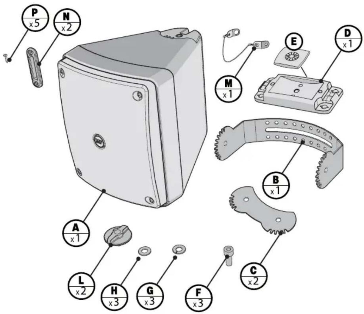
natural_image
Technical line drawing of a mechanical device with mounting holes and a circular outline (no text or symbols)- A loudspeaker MQ 80P
- B "U" bracket
- C linking support (x 2)
- D complete mounting accessory (with a bolt) for the "U" bracket +
- E plastic plate
-
F bolt (x3)
-
G washer (x3)
- H washer (x3)
- L round knob / bolt (x 2)
- M safety steel cable
- N reflex plug (x 2)
- P screw (x5)
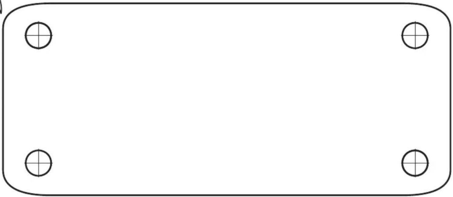
THE DRILLING TEMPLATE IS IN THIS MANUAL
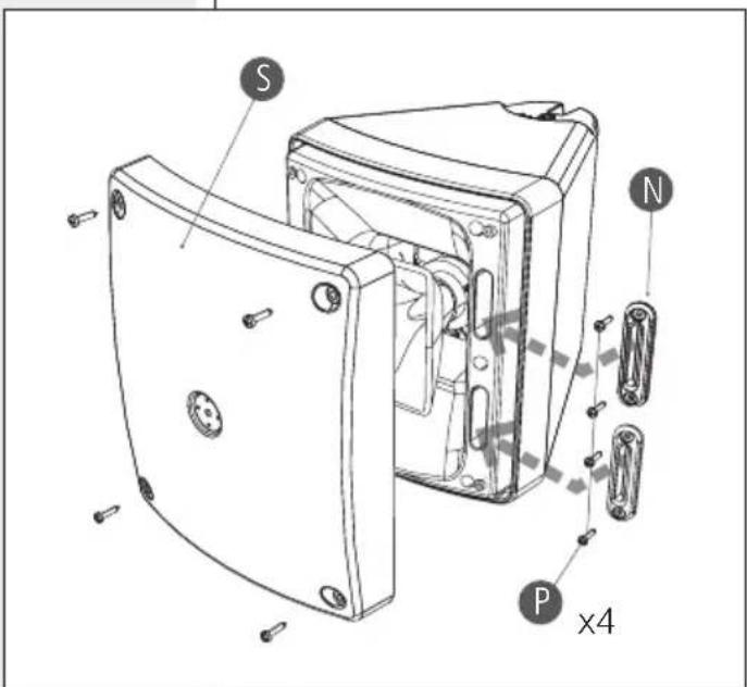
As default, MQ 80P is a bass-reflex lou speaker for indoor use. Yet, it can be also used outdoor (protection grade: IP 55) if adapted as a closed box:
- Take off the loudspeaker grille S by removing the four screws.
- Cover the two reflex ports (holes) by mounting the two plugs with rubber packings N, each to be fixed with two thread-forming screws P.
- Re-mount the loudspeaker grille S.
SINGLE LOUDSPEAKER INSTALLATION

A single loudspeaker can be installed to a wall either horizontally (coverage angle: 90^ hor. x 60^ vert.) or vertically ( 60^ hor. x 90 vert.).
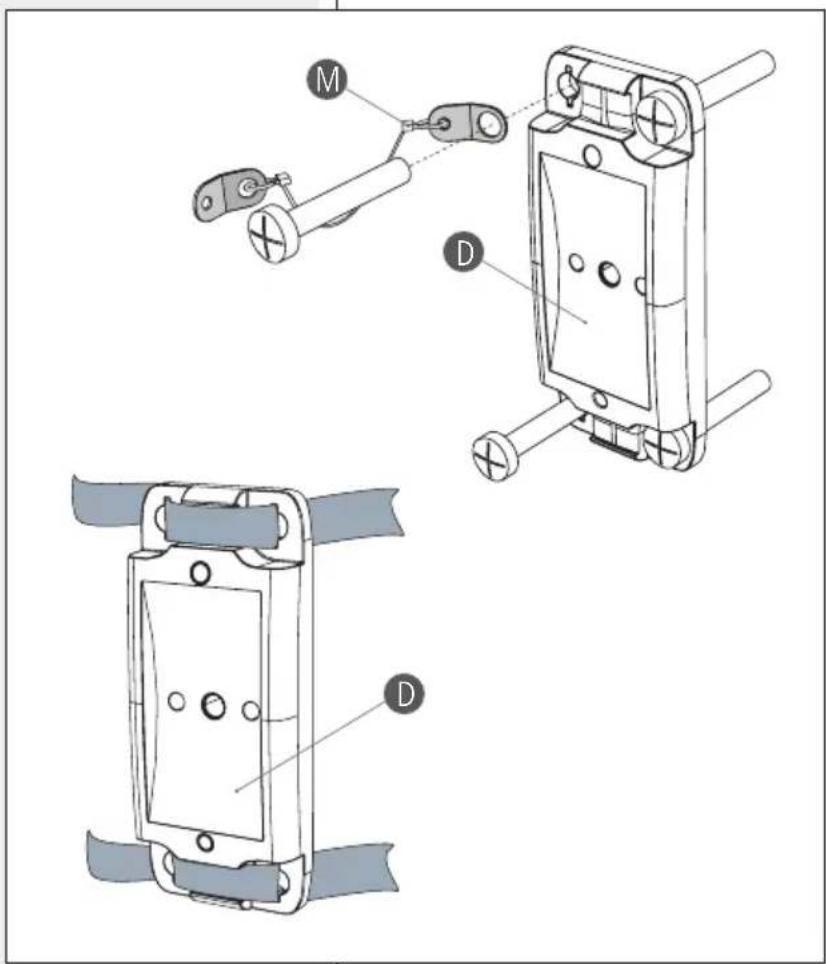
First fix the mounting accessory D to the wall through four M8 screws (not included, as these shall be chosen according to their support).
Fix the steel safety cable to the mounting accessory (by using a screw) M.
If the loudspeaker is installed vertically, the mounting accessory D can be also fixed to a pole by using two (up and down) clamping 13 mm (or 12 ", 12.7 mm) stainless steel bands.
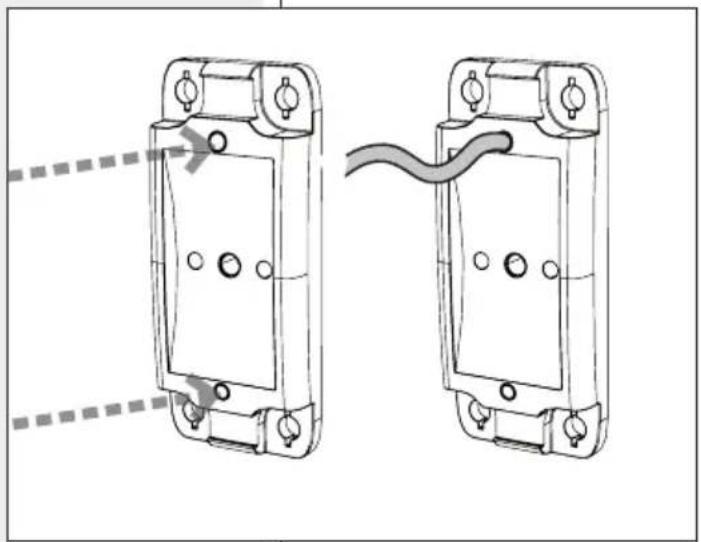
To get a weatherproof electrical connections and reduce the visible / external part of the loudspeaker cable (1 m long), this can pass through the "U" bracket, the mounting accessory hole (to be opened by pressing the plastic in one of the two available points) and its back seat, then inserted into the wall niche* (behind the mounting accessory) that houses electrical connections.
*It must be weatherproof in outdoor applications
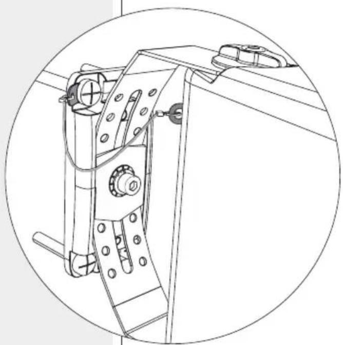
Put the "U" B bracket on the mounting accessory D and choose the right vertical* aiming angle (± 30°; each hole is a 7.5° step), then fix it by tightening the bolt F through the dedicated plastic plate E and washer G and H.
The "U" bracket allows a horizontal* loudspeaker aiming either 30^ to the right / 75^ to the left a or 75^ to the right / 30^ to the left b, according to its position. Every step is about 15^ .
* NOTE: ASSUMING THE LOUDSPEAKER IS INSTALLED VERTICALLY.
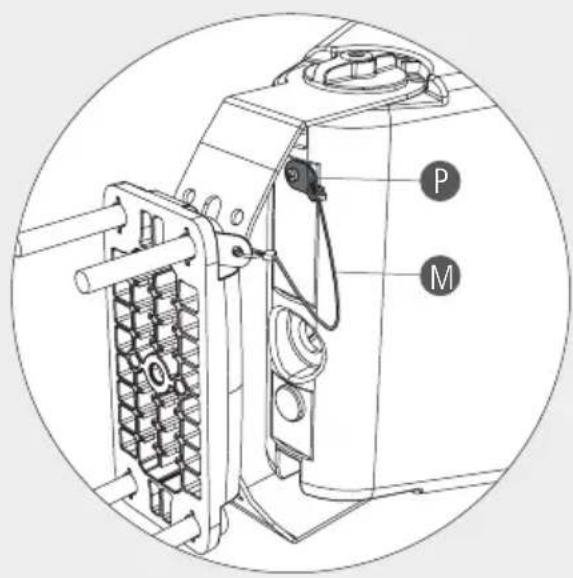
Use a screw P to fix the safety steel cable M as shown in this example.
natural_image
Technical line drawing of two mechanical components with mounting holes and a curved cable, shown from different angles (no text or symbols)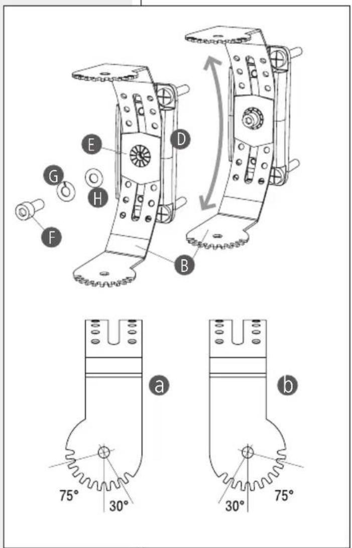
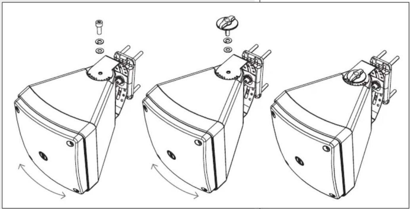
Insert the loudspeaker into the "U" bracket, aim it to the proper direction and fix it by tightening the two round knobs L or two bolts F (up and down), through the washers G and H. Bolts F are strongly suggested for outdoor installations.
natural_image
Technical line drawing of three mechanical components with assembly arrows indicating motion (no text or symbols)TWO LOUDSPEAKER CLUSTER

NOTE: FOR SAFETY REASONS, THE CLUSTER SHALL BE MADE HORIZONTALLY ONLY (BY PUTTING TOGETHER TWO LOUDSPEAKERS IN VERTICAL POSITION).

Install the mounting accessory and the "U" bracket (see the previous paragraph "Single loudspeaker installation")
It is necessary to use two linking supports (up and down) to make the two loudspeaker cluster.
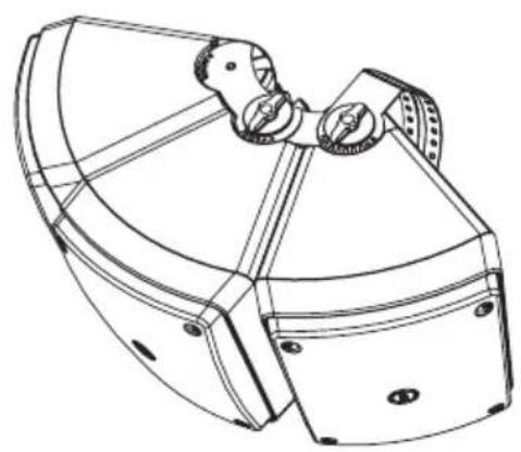
To fix the two loudspeakers and get the optimal 45^ angle between their axes (in order to get an uniform coverage), use the three spaces between teeth (of both sides, here pointed out in grey) closer to the centre.
Fix the two linking supports Ⓐ (up and down) by tightening the two round knobs or the two bolts to the (second) loudspeaker that will not be directly mounted on the "U" bracket.
Always place the washers G and H as previously indicated.
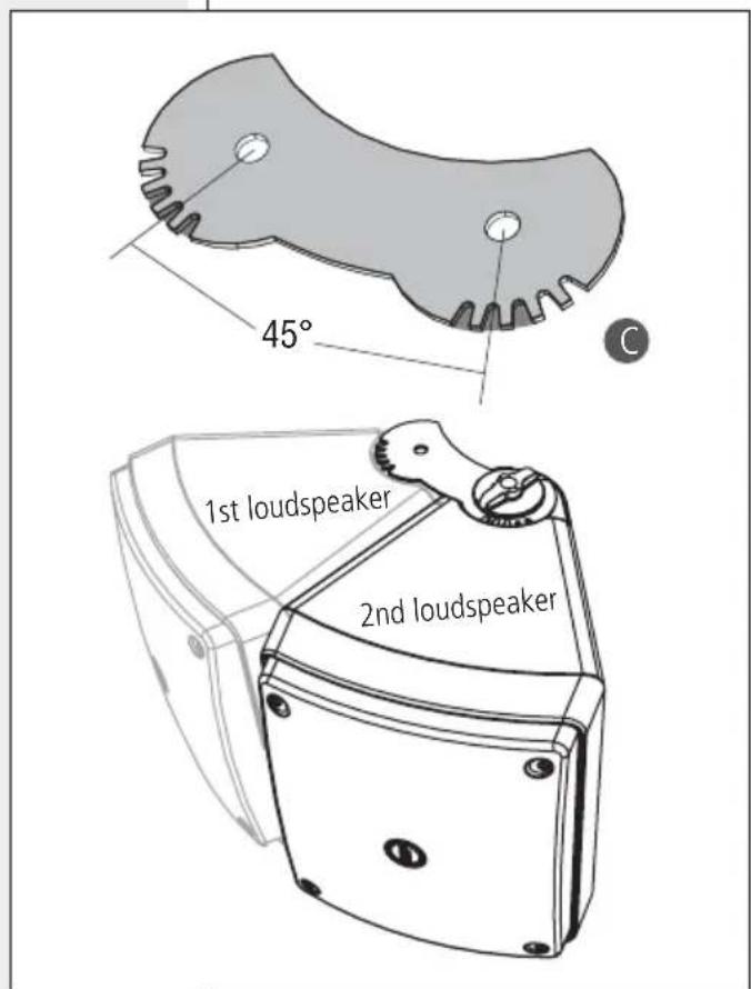
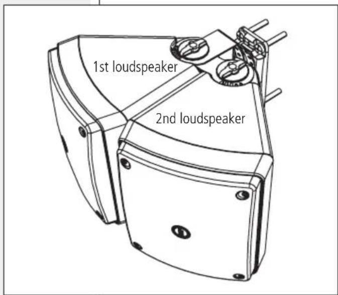
Mount the cluste to the "U" bracket by tightening other two round knobs or bolts to fix the first loudspeaker, and the two linking supports (with the second loudspeaker). Pay attention to the cluster horizontal aiming.
Fix the safety steel cables (previously attached to the mounting accessory screws) to loudspeakers
If necessary, loosen (just a little bit) the two round knobs / bolts of the second loudspeaker momentarily, in order to allow an easier insertion of the two linking supports on the first loudspeaker (then make sure all knobs are tightened properly).
THREE LOUDSPEAKER CLUSTER

NOTE: FOR SAFETY REASONS, THE CLUSTER SHALL BE MADE HORIZONTALLY ONLY (BY PUTTING TOGETHER THREE LOUDSPEAKERS IN VERTICAL POSITION).

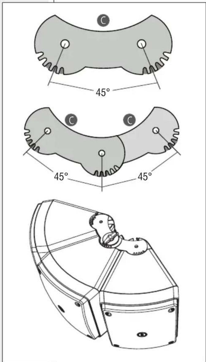
It is necessary to use four linking supports C (two up and two down) to make the three loudspeaker cluster.
To get the 45^ angle between the two loudspeaker axes, use the three spaces between teeth (of both sides, here pointed out in grey) closer to the centre of the linking support.
Put together two linking supports, in order to get a 45^ angle between the left and the central loudspeaker, a 45^ angle between the central and the right loudspeaker.
Make the cluster by putting the three loudspeakers together and fix the central one (and the four linking supports) by tightening two round knobs / bolts (up and down).
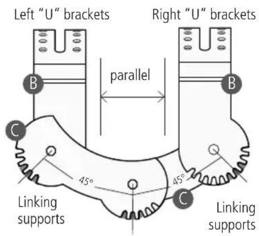
The cluster shall be wall-mounted by using two "U" brackets (in this example: the left "U" bracket is under the linking support, the right "U" bracket is on the linking support).
Both the "U" brackets are to be mounted parallel to the central loudspeaker axis: pay attention to the three spaces between teeth to be used (in this example, pointed out in grey in the right "U" brackets).
First mount the "U" bracket (the right one in this example) on the linking support and tighten the relevant two (up and down) round knobs / bolts.
Then add the other "U" bracket (the left one in this example) under the linking support and tighten the relevant two (up and down) round knobs / bolts.
Loosen (just a little bit) the two round knobs / bolts of the central loudspeaker momentarily, in order to allow an easier insertion of the "U" bracket.
Then, make sure all knobs are tightened properly.
Always place the washers G and H as previously indicated.
Now the cluster is ready to be fixed to the two wall-mounted accessories by tightening the two bolts.
NOTE: THE TWO MOUNTING ACCESSORIES ARE TO BE INSTALLED TO A WALL RESPECTING THE FIXED DISTANCE (CA.117 MM) BETWEEN THEIR AXES.
At the end of this manual, a drilling template is provided to simplify the installation of the two mounting accessories. Then the 3 safety steel cables (previously attached to the mounting accessory screws) can be fixed to the loudspeakers.
natural_image
Technical line drawing of a satellite dish antenna with no visible text or symbols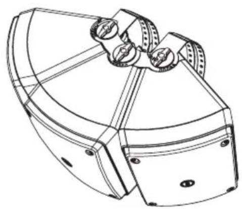
natural_image
Technical line drawing of a mechanical component with no visible text or symbols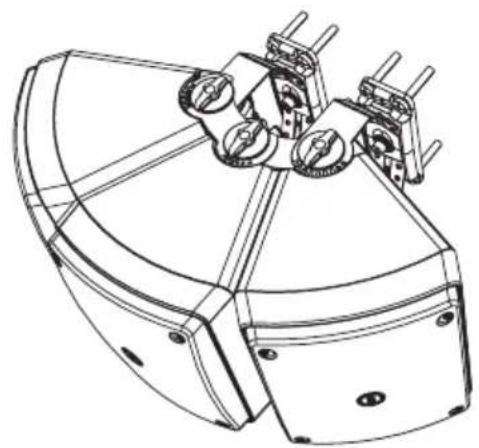
natural_image
Technical line drawing of a satellite dish antenna with multiple dish antennas mounted on its body (no text or symbols)WARNING: loudspeaker connections should be only made by qualified and experienced personnel having the technical know-how or sufficient specific instructions (to ensure that connections are made correctly) in order to prevent any electrical danger.
To prevent any risk of electric shock, do not connect loudspeakers when the amplifier is switched on.
Before turning the system on, check all connections and make sure there are no accidental short circuits.
The entire sound system shall be designed and installed in compliance with the current local laws and regulations regarding electrical systems.
If the loudspeaker is installed outdoor (IP 55), all electrical connections shall be inside weatherproof boxes / wall niches.
Connect its white wire to the line coming from the amplifier 100 V output (or 70 V); connect its black wire to line coming from the amplifier common output (or 0, b, —).
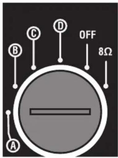
The internal transformer allows the connection to 100 V (/ 70 V) constant voltage lines and the power selection (during the installation) among 30 W, 20 W, 10 W, 5 W (half power if using 70 V lines). It is possible to select the low impedance (8 Ω) connection as well.
The power selection is made (by using a screw driver) through a rotary commutator, which is normally protected by a rubber cover (that must be removed momentarily).
Once the selector has been tapped, insert the rubber cover again.

| A 5 W (100 V) 2.5 W (70 V) | |
| B 10 W (100 V) 5 W (70 V) | |
| C 20 W (100 V) 10 W (70 V) | |
| D 30 W (100 V) 15 W (70 V) | |
| OFF not connected | |
| 8 Ω Impedance: 8 Ω | |
NOTES ABOUT CONSTANT VOLTAGE SYSTEMS

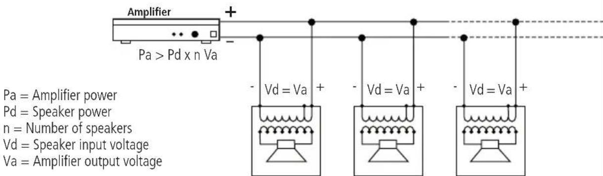
- The loudspeaker input voltage (Vd) must correspond to the amplifier output voltage (Va).
- The sum of nominal power values (Pd x n) of all loudspeakers connected to the line must not exceed the amplifier power (Pa).
- Make sure all loudspeakers are connected in phase to ensure a correct audio reproduction.
NOTES ABOUT LOW IMPEDANCE CONNECTIONS

- The total loudspeaker impedance must not be lower than the amplifier output impedance.
NOTE: A LOUDSPEAKER TOTAL IMPEDANCE EQUAL TO THE AMPLIFIER OUTPUT ONE PERMITS TO GET THE MAXIMUM DELIVERABLE POWER (BUT AN HIGHER LOUDSPEAKER IMPEDANCE ENTAILS LESS POWER). - The total loudspeaker power shall be adequate for the maximum deliverable power of the amplifier.
- The loudspeaker line shall be short (for long distances, it may be necessary to use cables with large cross-section wires).
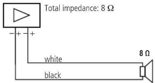
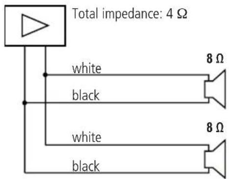
- Always use cables having wires with an adequate cross-section, considering the cable length and the total loudspeaker power.
- Loudspeaker lines must be kept separated from mains cables, microphone cables or others, in order to avoid inductive phenomena may cause hum or noises.
- Use loudspeaker cables with twisted wires to reduce hum caused by inductive effects due to coupling with electromagnetic fields.
- Do NOT use the 8 Ω setting when loudspeakers are connected to 100 / 70 V lines.
SPECIFICATIONS

TYPE - two-way bass reflex (indoor)
- two-way sealed (outdoor, IP 55), by adding the provided protections
- controlled directivity horn loaded 5" woofer
- controlled directivity horn loaded 1" compression driver.
LOUDSPEAKERS
SENSITIVITY
MAX. SOUND PRESSURE
(MUSICAL POWER)
POWER (BYPASS)
INPUT VOLTAGE
NOMINAL IMPEDANCE
94 dB (1 W / 1 m)
114 dB
60 W (RMS) / 120 W (musical)
100-70.7V
8 Ω (bypass)
333 Ω (30 W - 100 V; 15 W - 70.7 V)
500 Ω (20 W - 100 V; 10 W - 70.7 V)
1 kΩ (10 W - 100 V; 5 W - 70.7 V)
2 kΩ (5 W - 100 V; 2.5 W - 70.7 V)
(-10 dB) 100 Hz ÷ 20 kHz
3 kHz
90° horizontal x 60° vertical
(single horizontal installation)
high-density polystyrene
190×220×250mm
Black/White
WEIGHT
3 kg
AVVERTENZE PER LA SICUREZZA

IMPORTANTE
natural_image
Technical line drawing of a mechanical device with mounting holes and a ladder (no text or symbols)natural_image
Technical line drawing of two mechanical components with mounting holes and a curved cable, shown from different angles (no text or symbols)Use a screw P to fix the safety steel cable M as shown in this example.
natural_image
Technical line drawing of three mechanical components with assembly arrows indicating motion (no text or symbols)"CLUSTER" CON DUE DIFFUSORI

natural_image
Technical line drawing of a satellite dish antenna with no visible text or symbols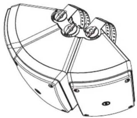
natural_image
Technical line drawing of a mechanical component with no visible text or symbols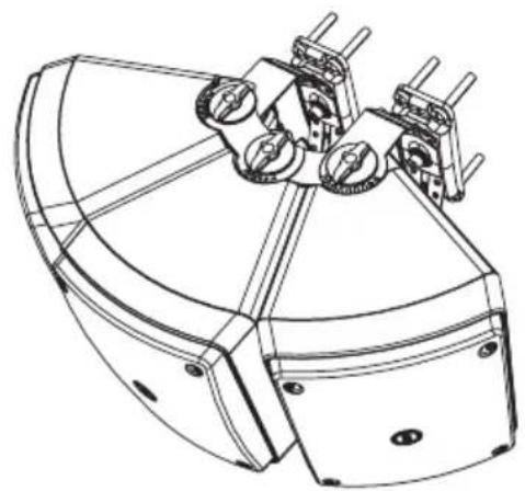
natural_image
Technical line drawing of a satellite dish antenna with multiple dish antennas mounted on its body (no text or symbols)60 W (RMS) / 120 W (musicale)
100-70,7 V
8 Ω (bypass)
333 Ω (30 W - 100 V; 15 W - 70,7 V)
500 Ω (20 W - 100 V; 10 W - 70,7 V)
1 kΩ (10 W - 100 V; 5 W - 70,7 V)
2 kΩ (5 W - 100 V; 2.5 W - 70,7 V)
100 Hz ÷ 20 kHz
3 kHz
natural_image
Technical line drawing of a mechanical device with mounting holes and a ladder (no text or symbols)natural_image
Technical line drawing of two mechanical components with mounting holes and a curved cable, shown from different angles (no text or symbols)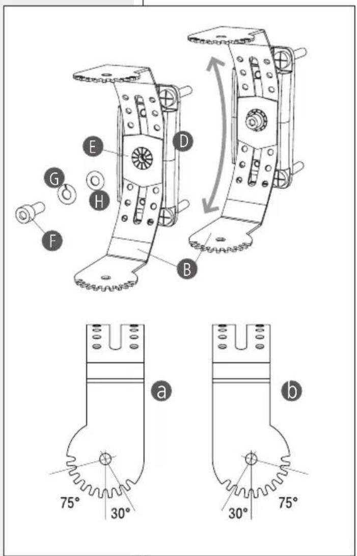
natural_image
Technical line drawing of three mechanical components with assembly arrows indicating motion (no text or symbols)2ER-LAUTSPRECHER-CLUSTER

installation/installazione/installation
natural_image
Empty rounded rectangle with four corner holes, no text or symbols present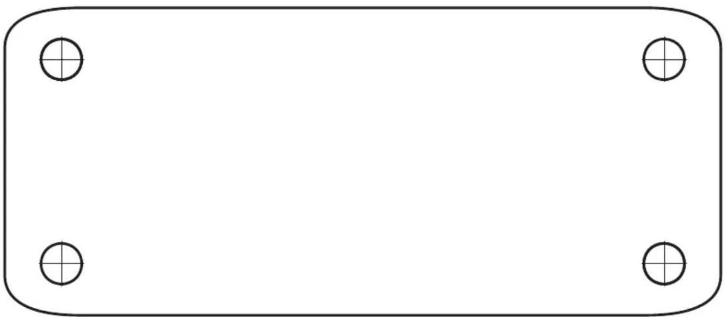
natural_image
Empty rounded rectangle with four corner holes, no text or symbols presentHEADQUARTERS:
RCF S.p.A. Italy
tel. +39 0522 274 411
e-mail: info@rcf.it
RCF UK
tel. 0844 745 1234
Int. +44 870 626 3142
e-mail: info@rcfaudio.co.uk
RCF France
tel. +33 1 49 01 02 31
e-mail: france@rcf.it
RCF Germany
tel. +49 2203 925370
e-mail: germany@rcf.it
RCF Spain
tel. +34 91 817 42 66
e-mail: info@rcfaudio.es
RCF Belgium
tel. +32 (0) 3 - 3268104
e-mail: belgium@rcf.it
RCF USA Inc.
tel. +1 (603) 926-4604
e-mail: info@rcf-usa.com
- SAFETY PRECAUTIONS
- IMPORTANT NOTES
- WARNING
- RCF S.p.A. strongly recommends this product is only installed by professional qualified installers (or specialised firms) who can ensure a correct installation and certify it according to the regulations in force.
- HEARING LOSS
- OPERATING PRECAUTIONS
- DESCRIPTION
- INSTALLATION NOTES
- SINGLE LOUDSPEAKER INSTALLATION
- TWO LOUDSPEAKER CLUSTER
- THREE LOUDSPEAKER CLUSTER
- NOTES ABOUT CONSTANT VOLTAGE SYSTEMS
- NOTES ABOUT LOW IMPEDANCE CONNECTIONS
- SPECIFICATIONS
- LOUDSPEAKERS
- SENSITIVITY
- SOUND PRESSURE
- (MUSICAL POWER)
- POWER (BYPASS)
- INPUT VOLTAGE
- NOMINAL IMPEDANCE
- WEIGHT
- AVVERTENZE PER LA SICUREZZA
- IMPORTANTE
- HEADQUARTERS:
Brand : RCF
Model : MQ 80P
Category : Loudspeaker