Omega AT-OME-MS52W - Router Atlona - Free user manual and instructions
Find the device manual for free Omega AT-OME-MS52W Atlona in PDF.


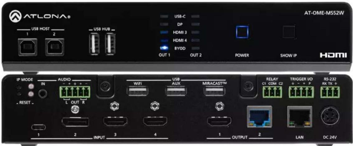
| Product Type | 5×2 AV Matrix Switcher with Wireless Gateway |
| Brand | Atlona |
| Model | Omega AT-OME-MS52W |
| Video Inputs | 2× HDMI, 1× USB-C, 1× DisplayPort, 1× Wireless (BYOD) |
| Video Outputs | 1× HDMI, 1× HDBaseT (RJ45) |
| Maximum Resolution | 4K/60 4:4:4 (HDMI), 4K/60 4:2:0 (HDBaseT); wireless up to 1080p |
| HDCP Compliance | HDCP 2.2 |
| Wireless Protocols | AirPlay, Google Cast, Miracast |
| USB Interfaces | 2× USB Host (Type B), 2× USB Hub (Type A), 1× USB-C (AV + data + charging up to 60W) |
| HDBaseT Distance | Up to 100 m (330 ft) at 1080p, 90 m at 4K |
| Audio | Analog audio in/out (3.5mm / captive screw), pass-through for LPCM, Dolby, DTS |
| Control | RS-232, IP (web server, Telnet), CEC, IR (via API) |
| Dimensions (H × W × D) | 1.65 × 8.62 × 10 in (42 × 219 × 254 mm) |
| Weight | 3.89 lbs (1.77 kg) |
| Power Supply | External 24 V DC, 6.25 A; input 100–240 V AC, 50/60 Hz |
| Power Consumption | 143 W max |
| Operating Temperature | 32 to 122 °F (0 to 50 °C) |
| Certifications | CE, FCC (Class A) |
| Warranty | 10-year limited (Award-winning) |
| Mounting | Rack ear and flat surface (under table) mounting |
| Package Contents | Main unit, 2 Wi-Fi antenna modules, USB-C cable, mounting plates, screws, rack ears, power supply, power cord, captive screw connectors, installation guide |
| Maintenance | Clean with dry cloth; do not expose to moisture |
| Spare Parts / Reparability | No user-serviceable parts; refer to qualified service personnel |
Frequently Asked Questions - Omega AT-OME-MS52W Atlona
User questions about Omega AT-OME-MS52W Atlona
0 question about this device. Answer the ones you know or ask your own.
Ask a new question about this device
Download the instructions for your Router in PDF format for free! Find your manual Omega AT-OME-MS52W - Atlona and take your electronic device back in hand. On this page are published all the documents necessary for the use of your device. Omega AT-OME-MS52W by Atlona.
USER MANUAL Omega AT-OME-MS52W Atlona
for HDMI, USB-C, DisplayPort, and HDBaseT™ with USB and Wireless Link
Version Information
Version Release Date Notes
9 Aug 2023 Added notes for internal USB hubs in specification table.
Sales, Marketing, and Customer Support
Main Office
Atlona Incorporated
70 Daggett Drive
San Jose, CA 95134
United States
Office: +1.408.962.0515
Sales and Customer Service Hours
Monday - Friday: 6:00 a.m. - 4:30 p.m. (PST)
https://atlona.com/
International Headquarters
Atlona International AG
Tödistrasse 18
8002 Zürich
Switzerland
Office: +41.43.508.4321
Sales and Customer Service Hours
Monday - Friday: 09:00 - 17:00 (UTC +1)
Operating Notes

IMPORTANT: Visit https://atlona.com/product/ome-ms52w/ for the latest firmware updates and User Manual.
Warranty

To view the product warranty, use the following link or QR code:
https://atlona.com/warranty/.
Safety and Certification
CAUTION
RISK OF ELECTRIC SHOCK
DO NOT OPEN
CAUTION: TO REDUCT THE RISK OF
ELECTRIC SHOCK
DO NOT OPEN ENCLOSURE OR EXPOSE
TO RAIN OR MOISTURE.
NO USER-SERVICEABLE PARTS
INSIDE REFER SERVICING TO
QUALIFIED SERVICE PERSONNEL

The exclamation point within an equilateral triangle is intended to alert the user to the presence of important operating and maintenance instructions in the literature accompanying the product.

The information bubble is intended to alert the user to helpful or optional operational instructions in the literature accompanying the product.
- Read these instructions.
- Keep these instructions.
- Heed all warnings.
- Follow all instructions.
- Do not use this product near water.
- Clean only with a dry cloth.
- Do not block any ventilation openings. Install in accordance with the manufacturer's instructions.
-
Do not install or place this product near any heat sources such as radiators, heat registers, stoves, or other apparatus (including amplifiers) that produce heat.
-
Do not defeat the safety purpose of a polarized or grounding-type plug. A polarized plug has two blades with one wider than the other. A grounding type plug has two blades and a third grounding prong. The wide blade or the third prong are provided for your safety. If the provided plug does not fit into your outlet, consult an electrician for replacement of the obsolete outlet.
- Protect the power cord from being walked on or pinched particularly at plugs, convenience receptacles, and the point where they exit from the product.
- Only use attachments/accessories specified by Atlona.
- To reduce the risk of electric shock and/or damage to this product, never handle or touch this unit or power cord if your hands are wet or damp. Do not expose this product to rain or moisture.
- Unplug this product during lightning storms or when unused for long periods of time.
- Refer all servicing to qualified service personnel. Servicing is required when the product has been damaged in any way, such as power-supply cord or plug is damaged, liquid has been spilled or objects have fallen into the product, the product has been exposed to rain or moisture, does not operate normally, or has been dropped.


FCC Compliance
FCC Compliance and Advisory Statement: This hardware device complies with Part 15 of the FCC rules. Operation is subject to the following two conditions: 1) this device may not cause harmful interference, and 2) this device must accept any interference received including interference that may cause undesired operation. This equipment has been tested and found to comply with the limits for a Class A digital device, pursuant to Part 15 of the FCC Rules. These limits are designed to provide reasonable protection against harmful interference in a commercial installation. This equipment generates, uses, and can radiate radio frequency energy and, if not installed or used in accordance with the instructions, may cause harmful interference to radio communications. However there is no guarantee that interference will not occur in a particular installation. If this equipment does cause harmful interference to radio or television reception, which can be determined by turning the equipment off and on, the user is encouraged to try to correct the interference by one or more of the following measures: 1) reorient or relocate the receiving antenna; 2) increase the separation between the equipment and the receiver; 3) connect the equipment to an outlet on a circuit different from that to which the receiver is connected; 4) consult the dealer or an experienced radio/TV technician for help. Any changes or modifications not expressly approved by the party responsible for compliance could void the user's authority to operate the equipment. Where shielded interface cables have been provided with the product or specified additional components or accessories elsewhere defined to be used with the installation of the product, they must be used in order to ensure compliance with FCC regulations.
Copyright, Trademark, and Registration
© 2022 Atlona Inc. All rights reserved. "Atlona" and the Atlona logo are registered trademarks of Atlona Inc. Pricing, specifications and availability subject to change without notice. Actual products, product images, and online product images may vary from images shown here.

The terms HDMI, HDMI High-Definition Multimedia Interface, and the HDMI Logo are trademarks or registered trademarks of HDMI licensing Administrator, Inc.
Dolby, Dolby Atmos, and the double-D symbol are registered trademarks of Dolby Laboratories Licensing Corporation.
For DTS patents, see http://patents.dts.com. Manufactured under license from DTS, Inc. DTS, the Symbol, DTS and the Symbol together, and Digital Surround are registered trademarks and/or trademarks of DTS, Inc. in the United States and/or other countries. © DTS, Inc. All Rights Reserved.
All other trademark(s), copyright(s), and registered technologies mentioned in this document are the properties of their respective owner(s).
Table of Contents
Introduction 7
Features 7
Package Contents 7
Panel Description 8
Front Panel 8
Rear Panel 9
Installation 10
Connectors 10
RS-232 10
Audio 10
Relay 11
Trigger I/O 11
Connection Instructions 12
Connection Diagram 14
IP Configuration 15
Getting the IP Address 15
Getting the IP Address without a Display 15
Switching the IP Mode Using the Front Panel 16
Auto IP Mode 16
Setting the IP Address using the Web Server 17
Resetting to Factory-Default Settings 18
Device Operation 19
LED Indicators 19
Logging in to the Web Server 20
Login Registration 20
Logging in after registration 21
Setting the System Date and Time 22
Automatic Adjustment 22
Setting Local Date and Time 23
Using an NTP Server 23
Selecting the Input 24
Switching Modes 25
Matrix Mode 25
Matrix Mode w/ Static Route 27
Auto-Switching 29
Enabling / Disabling Auto Switching 29
USB Modes 30
Manual 30
Auto Switch 31
Follow Video Input 32
The Splash Screen 34
Customizing Text 34
Displaying Metadata 37
Displaying the Wireless Password 38
Cycling Background Images 39
Uploading Custom Images 40
HTML Splash Screens 41
Resetting the HTML Splash Screen 44
Wireless Configuration 45
Access Point Mode 45
Firewall Mode 48
Connect to WiFi Mode 49
Changing the SSID 52
Table of Contents
802.1X Authentication 53
Ethernet Connections 53
WiFi Connections 55
Casting 56
iOS Devices 56
OS X Devices 57
Microsoft Miracast 59
Google Chrome 59
Audio Management 61
Using External Audio Sources 61
Controlling Audio Output Volume 61
AirPlay Bluetooth Discovery 62
AirPlay / Miracast P2P PIN Codes 63
Changing the PIN Timeout 65
Moderator Mode 66
Display Control Methods 69
Active Video Presence 69
Active Video Presence with Occupancy Sensor 71
Occupancy Sensor 72
Day and Time 74
Access Point 75
Changing the Password 76
Configuration and Management Interfaces 77
Web Server 77
Login Register page 77
Login page 78
Info page 79
General page 80
System page 81
Status page 84
Splash Screen page 85
Routing page 88
USB Routing page 89
Display page 90
EDID page 96
Administration > Telnet page 97
Administration > Moderator page 98
Administration > Networking page 99
Administration > Debug page 105
Administration > User Accounts page 106
Administration > Advanced page 107
Administration > Pre-Release page 112
Administration > Audio page 113
Administration > Event Viewer page 114
Appendix 115
Updating the Firmware 115
Mounting Instructions 117
Single-unit Rack Installation 117
Dual-unit Rack Installation 118
Flat Surface 119
Specifications 120
Introduction
The Atlona AT-OME-MS52W is a 5x2 matrix switcher with HDMI, USB-C, DisplayPort, and wireless AV inputs, plus HDMI and HDBaseT outputs. It features wireless presentation capability and native screen mirroring for iOS ^® , Android ^™ , Mac ^® , Chromebook ^™ , and Windows ^® . Part of the Omega ^™ Series of integration products for modern AV communications and collaboration, the OME-MS52W is HDCP 2.2 compliant and features HDBaseT extension for video up to 4K/60 4:2:0, plus embedded audio, control, Ethernet, and USB over distances up to 330 feet (100 meters). All inputs and the local HDMI output support 4K HDR and 4K/60 4:4:4 at HDMI data rates up to 18 Gbps. The integrated USB extension addresses the challenge of connecting between USB devices at remote locations, and is ideal for software video conferencing and touch or interactive displays. The OME-MS52W includes USB 2.0 and USB-C interfaces for three host PCs, plus two peripheral ports for devices such as a camera, microphone, speakerphone, or keyboard and mouse.
Features
- 5×2 AV matrix switcher
• USB-C input for AV, data, and device charging - HDBaseT and HDMI outputs with selectable AV switching modes
- Wireless AV gateway
- Native platform-based, wireless interfacing
• Moderator mode for wireless AV presentations
• Video, audio, power, and data over category cable utilizing HDBaseT technology (1)
• USB 2.0 interfacing and extension over HDBaseT
• Automatic input selection and automatic display control - Contact closure for screen or display lift control
- Trigger I/O ports for occupancy sensing
- Award-winning 10 year limited product warranty
Package Contents
1 x AT-OME-MS52W
1 x Captive screw connector, 5-pin
1 x Captive screw connector, 3-pin
2 x Wi-Fi antenna modules
1 x USB-C cable
2 x Mounting plate
4 x Mounting screw
1 x Long rack ear
1 x Short rack ear
4 x Feet w/rubber grips
1 x 24 V DC power supply
1 x IEC power cord
1 x Installation Guide
(1) Maximum 120 Mbps data rate supported over HDBaseT.
Panel Description
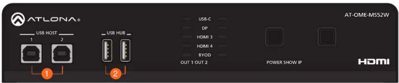
Front Panel
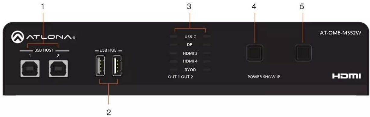
1 USB HOST
Connect a USB cable from each of these ports to host computers.
2 USB HUB
Connect up to two USB devices (e.g. mouse, keyboard, etc.) to these ports. These ports provide 2.5 W per USB device interface.
3 OUT 1 / OUT 2 LED Indicators
Each set of LED indicators displays the output being used: OUT 1 = HDMI OUT, OUT 2 = HDBaseT OUT.
4 POWER
Press this button to power-on or power off the AT-OME-MS52W and/or the connected displays.
5 SHOW IP
Press this button to display the IP address of the ATOME-MS52W on the connected display.
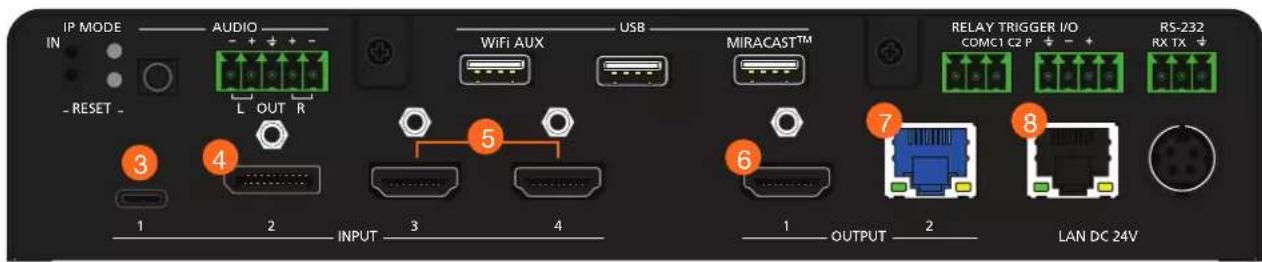
Rear Panel
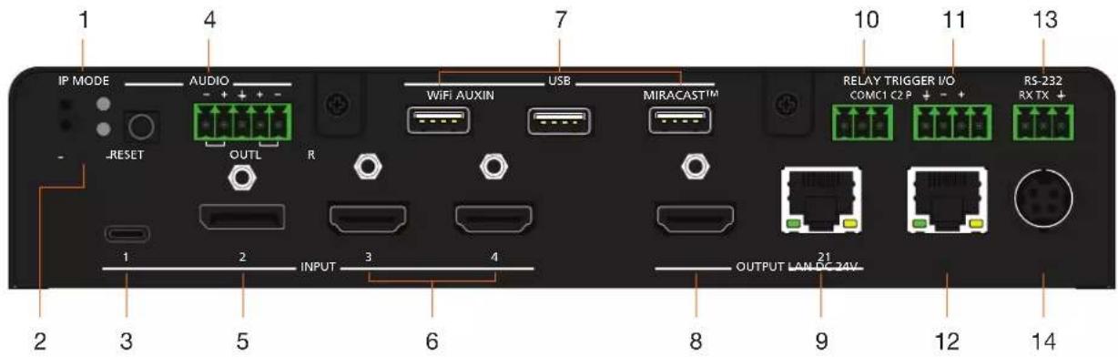
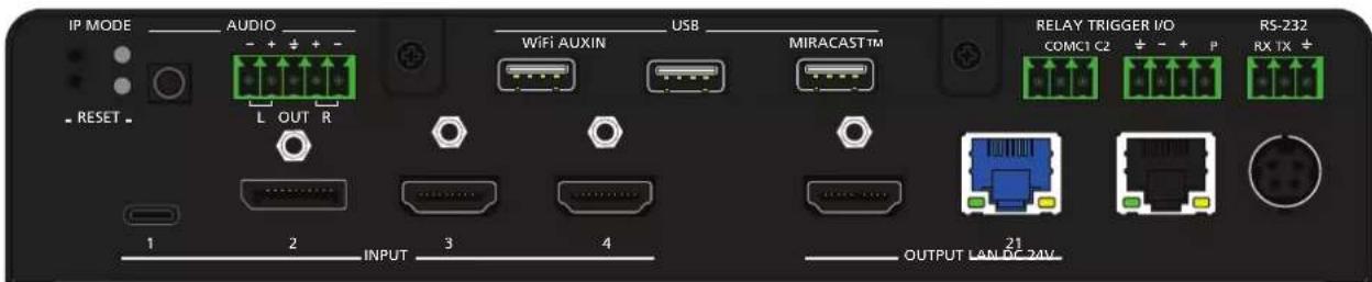
1 IP MODE
Press and release this button to set the IP mode of the AT-OME-MS52W. Refer to IP Configuration (page 15) for more information.
2 RESET
Press and release this button to reset the unit to factory-default settings. Refer to Resetting to Factory-Default Settings (page 18) for more information.
3 INPUT (USB-C)
Connect a USB-C cable from this port to a USB-C source.
4 AUDIO
Connect a 3.5 mm mini-stereo cable from an analog audio source to the IN port, to provide optional embedded analog audio on the output. Connect a balanced stereo audio output device to the OUT port using the included captive screw block for audio de-embedding. Refer to Audio (page 10) for wiring information.
Connect a DisplayPort device to this port.
6 INPUT (HDMI)
Connect an HDMI cable from each of these ports to a UHD/HD source.
7 USB HUB
Connect the included WiFi antenna to these ports. The MIRACAST port is reserved for the Miracast casting protocol. The AUX port is reserved for system use.
8 OUTPUT (HDMI)
Connect an HDMI cable from this port to an HD/UHD display.
9 OUTPUT (HDBaseT)
Connect to a locally powered HDBaseT receiver such as the AT-OME-EX-RX.
10 RELAY
Connect one of the included 3-pin captive screw connectors to this port to control screens, drapes, lights, or other devices.
11 TRIGGER I/O
Connect voltage-controlled device to this port. A 4-pin captive screw connector is required.
12 LAN
Connect an Ethernet cable from this port to the network.
13 RS-232
Use the included 3-pin captive screw connector to connect an RS-232 controller or automation system.
14 DC 24V
Connect the included 24 V DC power supply from this power receptacle to an available AC electrical outlet.
Installation
Connectors
RS-232
The AT-OME-MS52W provides an RS-232 port which can be used to control a display connected to the HDMI output. Atlona recommends controlling the AT-OME-MS52W using IP and reserving the RS-232 port for local display control.
- Use wire strippers to remove a portion of the cable jacket.
- Remove at least 3/16" (5 mm) of insulation from each of the wires.
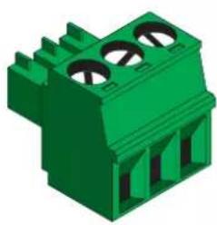
- Insert the wires into correct terminal using the included 3-pin captive screw connector.
- Attach the 3-pin connector block to the RS-232 port on the AT-OME-MS52W.
natural_image
Green 3D component with three circular holes, no text or symbols visible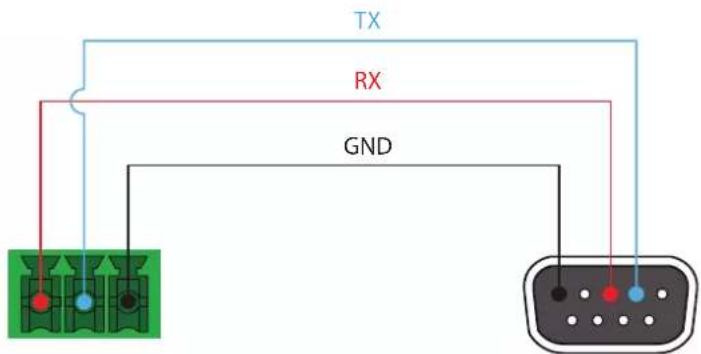
Audio
The AT-OME-MS52W provides the ability to output two-channel balanced analog audio on the AUDIO OUT port, using the included 5-pin captive screw connector.
Use wire strippers to remove enough insulation to allow each wire to be securely fastened to each terminal of the captive screw connector block and connect the wires as shown.
natural_image
Green 3D component with multiple slots and mounting holes (no text or symbols visible)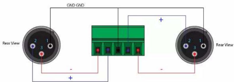

NOTE: If unbalanced audio is needed, then it is recommended to use a stereo balanced to unbalanced converter.
Installation
Relay
The AT-OME-MS52W provides a RELAY port, allowing the control of screens, curtains, and other devices.
The RELAY port supports up to 48 V DC with no more than 1 A current draw.
When the AT-OME-MS52W is powered-on or rebooted, C1 and C2 are set to the Normally Open (NO) state.
natural_image
Green 3D mechanical component with three circular holes (no text or symbols visible)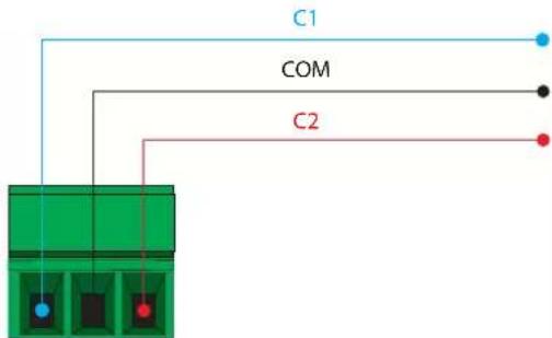
Trigger I/O
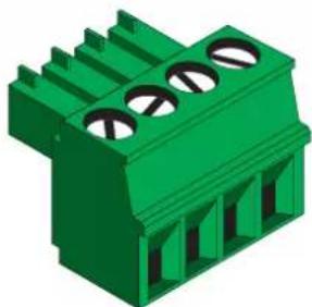
The TRIGGER I/O port allows voltage-controlled devices, such as an occupancy sensor, to be connected to the AT-OME-MS52W. Use the included 4-pin captive screw connector to connect the device. Voltage range is +3 to +30 V DC. 0 V = Off. +3 to +30 V DC = On.
natural_image
Green 3D component with three circular holes and vertical supports (no text or symbols)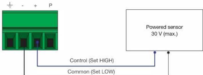
Powered sensor
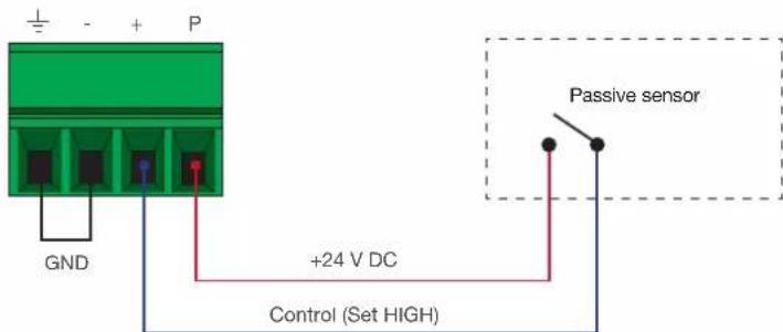
Passive sensor
Connection Instructions
- Connect up to two USB host computers to the USB HOST ports on the front panel.
- Connect two USB devices, such as a speakerphone, to the USB HUB ports on the front panel.
- Connect a USB-C cable from a source to the USB-C (1) port.
- Connect a DisplayPort cable from a source to the DP IN (2) port.
- Connect up to two UHD/HD sources, using HDMI cables, to the HDMI IN (3) and HDMI IN (4) ports.
- Connect an HDMI cable from the HDMI OUT port to a UHD/HD display.
- Connect a category cable (CAT-5e or better), up to 330 feet (100 meters), from the HDBaseT OUT port to a compatible receiver, such as the AT-OME-EX-RX.
- Connect an Ethernet cable from the LAN port to the Local Area Network (LAN). Atlona recommends this step and provides access to the built-in web server, which can be used to control and manage the AT-OME-MS52W.
| Core | Shielding | CAT5e | CAT6 | CAT6a | CAT7 |
| Solid | UTP (unshielded) | N/A | |||
| STP (shielded) |
| Cable | Max. Distance @ 4K | Max. Distance @ 1080p |
| CAT5e | 295 feet (90 meters) | 330 feet (100 meters) |
| CAT6a / CAT6a / CAT7 | 330 feet (100 meters) | 330 feet (100 meters) |

IMPORTANT: Stranded or patch cable is not recommended due to performance issues.
Sheilded cables are strongly recommended to minimize signal noise and interference.
Installation
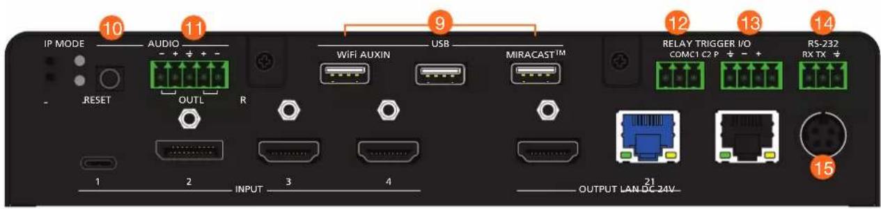
- Connect the included USB wireless antennas to the WiFi and MIRACAST™ ports. The WiFi port supports Google Cast™ and Apple AirPlay®. The MIRACAST™ only supports Miracast.

IMPORTANT: Only use Atlona WiFi USB modules. Other WiFi modules may not be supported by this product.
- OPTIONAL: Connect a 3.5 mm analog audio cable from an analog source to the AUDIO IN port. This audio source can be used to embed analog audio on any of the input sources.
- OPTIONAL: Connect the included green 5-pin captive screw connector to the AUDIO OUT connector. Refer to Audio (page 10) for wiring information.
- OPTIONAL: Connect the relay leads from the control motors of the projection screen, blinds, or curtains, to the relay outputs to the RELAY port, using the included 3-pin captive screw connector. Use a 48 V DC relay with no more than 1 A current draw. Refer to Relay (page 11) for wiring information.
- OPTIONAL: Connect a trigger device, such as an occupancy sensor switch, to the TRIGGER I/O port. A 4-pin captive screw connector is required. Voltages from 3 to 30V are supported. Refer to Trigger I/O (page 11) for wiring information.
- OPTIONAL: Use the included captive screw connector to connect a serial cable from the RS-232 port on the ATOME-MS52W, to the RS-232 port on the display. Refer to RS-232 (page 10) for wiring information.
- Connect the included power supply to the DC 24V connector and connect the power cord to an available electrical outlet. Connect the included power supply to the DC 24V connector and connect the power cord to an available electrical outlet.

NOTE: The AT-OME-MS52W may take up to five minutes to complete the initial boot process.
Installation
Connection Diagram
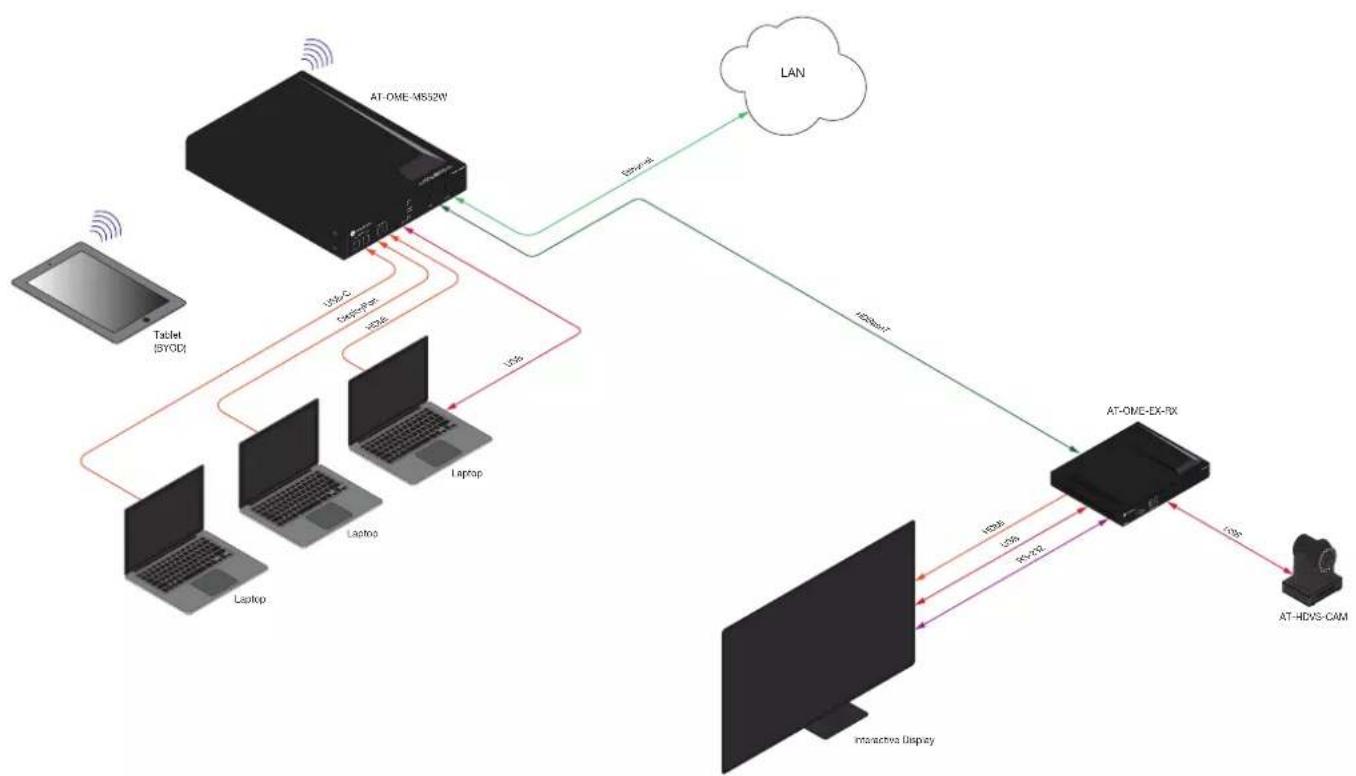
flowchart
graph TD
    A["AT-OME-MS12W"] -->|Ethernet| B["LAN"]
    A -->|IPv6| C["AT-OME-EX-RX"]
    C -->|IPv6| D["AT-HDVS-CAM"]
    C -->|IPv6| E["Laptop"]
    C -->|IPv6| F["Laptop"]
    C -->|IPv6| G["Laptop"]
    C -->|IPv6| H["Laptop"]
    C -->|IPv6| I["Laptop"]
    C -->|IPv6| J["Laptop"]
    C -->|IPv6| K["Laptop"]
    C -->|IPv6| L["Laptop"]
    C -->|IPv6| M["Laptop"]
    C -->|IPv6| N["Laptop"]
    C -->|IPv6| O["Laptop"]
    C -->|IPv6| P["Laptop"]
    C -->|IPv6| Q["Laptop"]
    C -->|IPv6| R["Laptop"]
    C -->|IPv6| S["Laptop"]
    C -->|IPv6| T["Laptop"]
    C -->|IPv6| U["Laptop"]
    C -->|IPv6| V["Laptop"]
    C -->|IPv6| W["Laptop"]
    C -->|IPv6| X["Laptop"]
    C -->|IPv6| Y["Laptop"]
    C -->|IPv6| Z["Laptop"]
    C -->|IPv6| AA["Laptop"]
    C -->|IPv6| AB["Laptop"]
    C -->|IPv6| AC["Laptop"]
    C -->|IPv6| AD["Laptop"]
    C -->|IPv6| AE["Laptop"]
    C -->|IPv6| AF["Laptop"]
    C -->|IPv6| AG["Laptop"]
    C -->|IPv6| AH["Laptop"]
    C -->|IPv6| AI["Laptop"]
    C -->|IPv6| AJ["Laptop"]
    C -->|IPv6| AK["Laptop"]
    C -->|IPv6| AL["Laptop"]
    C -->|IPv6| AM["Laptop"]
    C -->|IPv6| AN["Laptop"]
    C -->|IPv6| AO["Laptop"]
    C -->|IPv6| AP["Laptop"]
    C -->|IPv6| AQ["Laptop"]
    C -->|IPv6| AR["Laptop"]
    C -->|IPv6| AS["Laptop"]
    C -->|IPv6| AT["Laptop"]
    C -->|IPv6| AU["Laptop"]
    C -->|IPv6| AV["Laptop"]
    C -->|IPv6| AW["Laptop"]
    C -->|IPv6| AX["Laptop"]
    C -->|IPv6| AY["Laptop"]
    C -->|IPv6| AZ["Laptop"]
    C -->|IPv6| BA["Laptop"]
    C -->|IPv6| BB["Laptop"]
    C -->|IPv6| BC["Laptop"]
    C -->|IPv6| BD["Laptop"]
    C -->|IPv6| BE["Laptop"]
    C -->|IPv6| BF["Laptop"]
    C -->|IPv6| BG["Laptop"]
    C -->|IPv6| BH["Laptop"]
    C -->|IPv6| BI["Laptop"]
    C -->|IPv6| BJ["Laptop"]
    C -->|IPv6| BK["Laptop"]
    C -->|IPv6| BL["Laptop"]
    C -->|IPv6| BM["Laptop"]
    C -->|IPv6| BN["Laptop"]
    C -->|IPv6| BO["Laptop"]
    C -->|IPv6| BP["Laptop"]
    C -->|IPv6| BQ["Laptop"]
    C -->|IPv6| BR["Laptop"]
    C -->|IPv6| BS["Laptop"]
    C -->|IPv6| BT["Laptop"]
    C -->|IPv6| BU["Laptop"]
    C -->|IPv6| BV["Laptop"]
    C -->|IPv6| BW["Laptop"]
IP Configuration
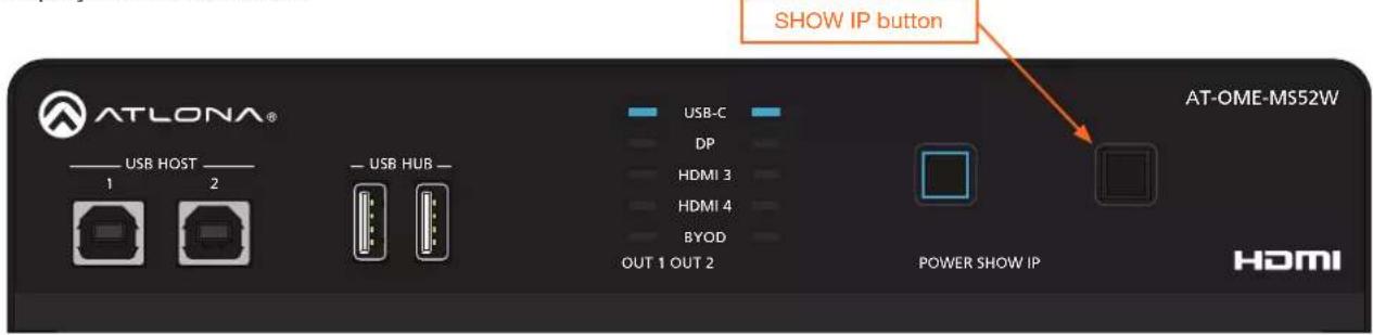
The AT-OME-MS52W is shipped with DHCP enabled. Once connected to a network, the DHCP server (if available), will automatically assign an IP address to the unit. Pressing the SHOW IP button will display the current IP address of the AT-OME-MS52W. Alternatively, an IP scanner, along with the MAC address on the bottom of the unit, can also be used to identify the unit on the network.
Getting the IP Address
- Make sure the AT-OME-MS52W is powered.
- Connect a display to the HDMI output (OUTPUT 1). Make sure the display is powered.
- Press and release the SHOW IP button on the front panel. The IP address of the AT-OME-MS52W will be displayed on the screen.
Getting the IP Address without a Display
If a display device is unavailable, use the following procedure to obtain the IP address of the AT-OME-MS52W.
- Make sure the AT-OME-MS52W is powered and ready for operation.
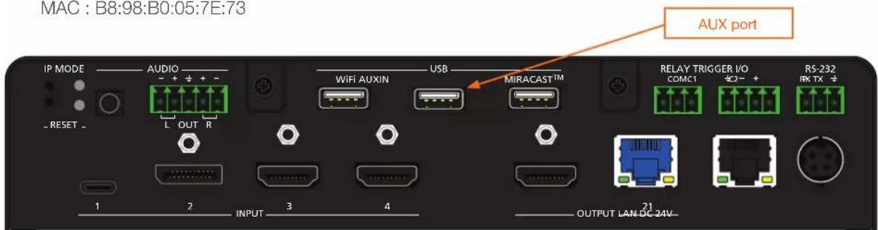
- Insert a USB drive into the AUX port and wait approximately 10 seconds, then remove the USB drive from the AUX port insert the drive into an available USB port on a computer.
- Two files will be present on the USB drive. One file is formatted for Windows and the other is formatted for Linux.
Windows: AtlonaReport-Win-GWB-20170821200241.txt
Linux: AtlonaReport-Unix-GWB-20170821200241.txt
- Double-click the desired file to open it. The IP address of the AT-OME-MS52W is listed under Ethernet #1. An example is shown below.
Ethernet #1
IP:192.168.41.68
MAC : B8:98:B0:05:7E:73
Switching the IP Mode Using the Front Panel
If a static IP address is desired, the unit can be switched to static IP mode. Use one of the following procedures to switch between DHCP and static IP mode. The default static IP address of the AT-OME-MS52W is 192.168.1.254. If the AT-OME-MS52W is unable to detect a DHCP server within 15 seconds, then the unit will use a self-assigned IP address within the IPv4 address block 169.254.0.0/16. If this occurs, refer to Auto IP Mode (page 16) for more information.
- Make sure the AT-OME-MS52W is powered.
- Press and hold the IP MODE button for at least 15 seconds.
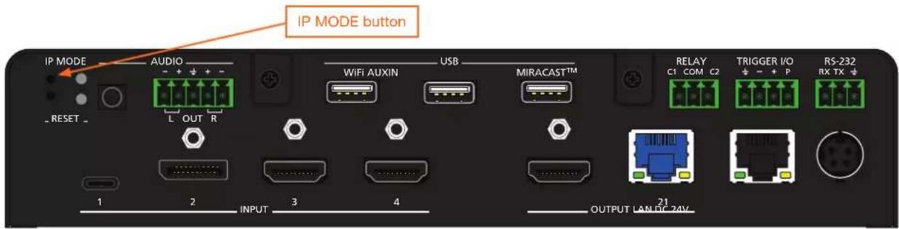
- Release the INPUT button once all the front-panel LED indicators begin to flash. This will cause the unit to reboot which may take up to five minutes. The number of flashes will indicate the currently selected IP mode:
Input LED Indicators flash Description
| Two DHCP mode | |
| Four Factory Static IP mode (IP address set to 192.168.1.254) | |
Auto IP Mode
If the AT-OME-MS52W is unable to detect a DHCP server within 15 seconds, then the unit will use a self-assigned IP address within the IPv4 address block 169.254.0.0/16. If this occurs, connect an Ethernet cable directly from the LAN port of the AT-OME-MS52W to the LAN port of a computer, then do the following:
- Click Start > Settings > Control Panel > Network and Sharing Center.
- Click Change adapter settings.
- Right-click on the adapter that is used to establish a wired connection to the network, and select Properties from the context menu.
- Under the Ethernet Properties dialog box, select Internet Protocol Version 4 and then click the Properties button. Click the Use the following IP address radio button.

IMPORTANT: Before continuing, write down the current IP settings in order to restore them, later. If Obtain an IP address automatically and Obtain DNS server automatically are selected, then this step is not required.
- Enter the desired static IP address or the IP address provided by the network administrator. If the computer does not require Internet access or if a statically-assigned IP address is being used, then an address within the IPv4 address block 169.254.0.0/16 can be entered.
- Set the subnet mask to 255.255.0.0.
- Click the OK button then close all Control Panel windows.
Installation
Setting the IP Address using the Web Server
The IP mode of the AT-OME-MS52W can also be set using the built-in web server. In order to access the web server, the IP address of the AT-OME-MS52W must be known. Refer to Logging in to the Web Server (page 20) for more information.
- Open the desired web browser and enter the IP address of the AT-OME-MS52W.
- Login using the required credentials.
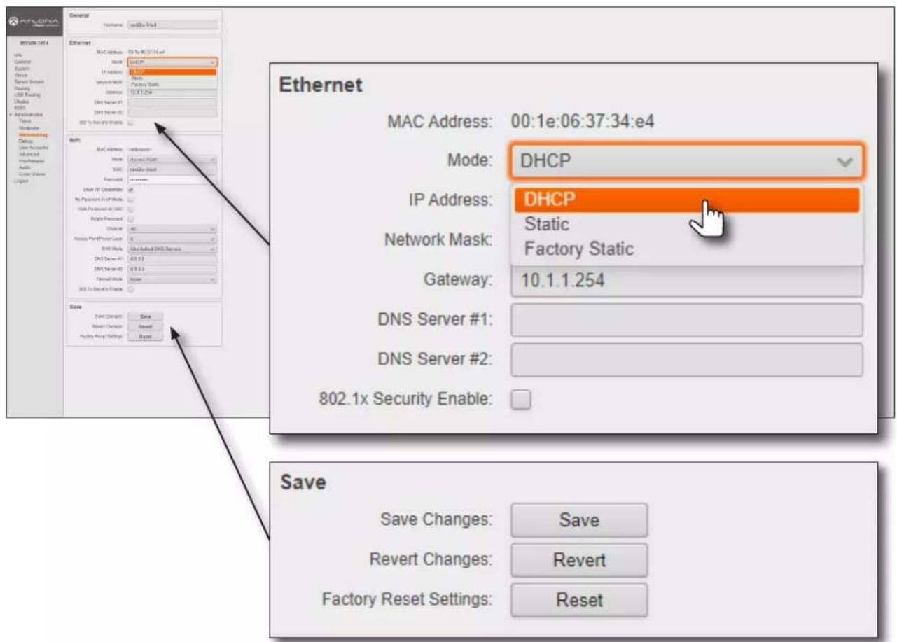
- Click Administration > Networking.
- Under the Ethernet window group, click the Mode drop-down list to select DHCP, Static, or Factory Static. If set to Static, the IP, Network Mask, Gateway fields can be modified.
If set to Factory Static, then the IP settings will be set to the following values:
IP Address 192.168.1.254
Network Mask 255.255.0.0
Gateway 192.168.1.1
Both DNS Server fields can be modified when set to either Static or Factory Static mode.
- Under the Save window group, click the Save button, next to Save Changes, to commit changes.

NOTE: When saving network settings, the AT-OME-MS52W may prompt for a reboot.
Resetting to Factory-Default Settings
- Press and hold the RESET button for five seconds.
- Release the RESET button once the RESET LED indicator begins to flash. The LED indicator will flash three times to indicate that the unit has been reset to factory-default settings.
Device Operation
LED Indicators
The LED indicators on both the front and rear of the unit provide basic information on the current status of the AT-OME-MS52W. The POWER button has a backlit LED indicator.
| LED Description | |||
POWER Solid blue • Unit is power  and is in normal operating mode. and is in normal operating mode. | |||
| USB-C DP HDMI 3 HDMI 4 BYOD | Solid blue • The input is   | the currently selected (active) input. | |
Off • The input is  | active. | ||
| IP MODE | Flash green (4x)  | • Flashes four times to indicate that the unit is being set to DHCP mode. Refer to IP Configuration (page 15) for more information. | |
Flash green (2x) •  | hes twice to indicate that the unit is being set to static IP mode and will be assigned the IP address of 192.168.1.254. | ||
| Off • Normal operation mode | mode. | ||
| RESET | Flash green (3x)  | • Unit is being set to factory-default settings. Refer to Resetting to Factory-Default Settings (page 18) for more information. | |
| Off • Normal operating mode. | mode. | ||
Logging in to the Web Server
Most of the AT-OME-MS52W operation is handled through the built-in web server. In order to access the web server, the IP address of the unit must be known. Refer to IP Configuration (page 15) for more information.
Login Registration
- Launch the desired web browser and enter the IP address of the AT-OME-MS52W in the address bar.
- The AT-OME-MS52W Login Registration page will be displayed.
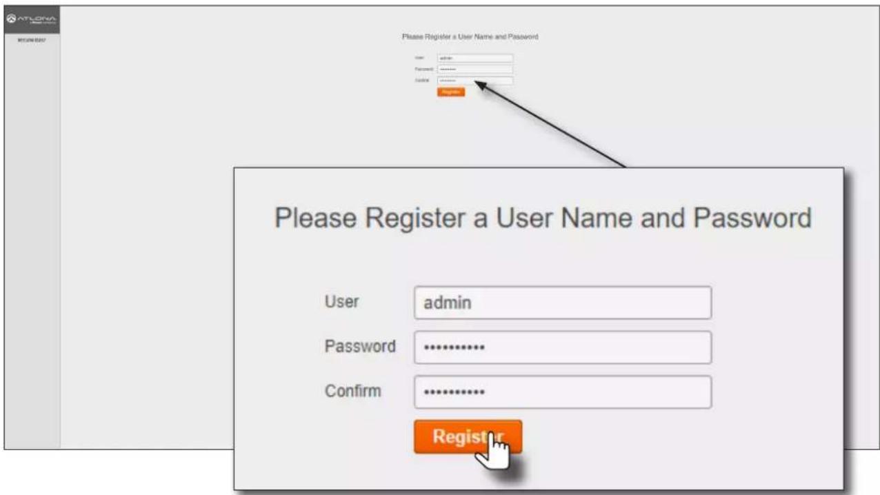
- Enter the desired username in the User field. In the example above, the username admin is used.
- Enter the desired password in the Password field.

IMPORTANT: The password must contain a minimum of 8 characters, including: 1 uppercase character, 1 lowercase character, and 1 number. Note that the Password and Confirm fields will be masked when entering the password.
- Verify the password by entering it in the Confirm field.
- Click the Register button.
- The Info screen will be displayed. Refer to Info page (page 79) for more information.
- The login registration process is complete.
Logging in after registration
- Launch the desired web browser and enter the IP address of the AT-OME-MS52W in the address bar.
- Enter the correct username and password in the respective fields.
- Click the Login button.

NOTE: If using a secure connection, click the Secure Login button.
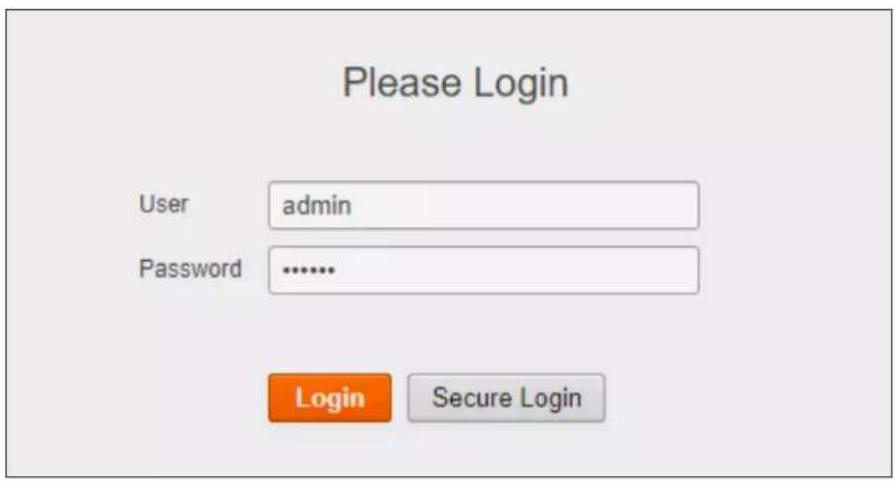
- The Info page will be displayed and the login process is complete. Refer to Info page (page 79) for more information.
Setting the System Date and Time
The AT-OME-MS52W uses the internal clock to store the current date and time. When setting the time and date, Universal Coordinated Time (UTC) must be used.

IMPORTANT: In order for proper unit operation, it is critical that the AT-OME-MS52W be set to the correct UTC time setting.
Automatic Adjustment
- Login to the web server. Refer to Logging in to the Web Server (page 20) for more information.
- Click System in the side menu bar.
- Under the Time window group, click the here link to launch a web browser and obtain the current UTC. Both the current local time and date will be set.

NOTE: Date and time can also be manually adjusted by clicking the Set button. However, this is not recommended.
![SYSTEM Display Name: WEDY-364 Symbol: Reason Shelfing: Shelfing Factors: Reason Time Current Date / Time: Set Mar 16 2022, 20:42 [UTC] • System time must be set as UTC. Find the current time (up): Local Date / Time: Set MTP Server: pool.ntp.org Firmware Model/Name: AT ONE MSCI Marker Version: J.4.4 Preview Version: 1.4.2K Preview Chain: Quick Update Provider: Upload • Please be not changed to https://www.mcp.org/MCBI software Configuration Command: Download Order: Upload Documentation Local Service: Download Document Tools: Download All Documentation: Download Time System Date / Time: Set Mar 16 2022, 20:42 [UTC] • System time must be set as UTC. Find the current time here. Local Date / Time: Set NTP Server: pool.ntp.org](/content/2026/05/896898/images/8c8ea0bd36d3ff2dc7b61807bdd2c581f0e2911673bab2d78de40828029e9791.jpg)
Setting Local Date and Time

IMPORTANT: If the Local Date / Time field appears highlighted in red (shown above), then this task must be performed to ensure proper functionality of the AT-OME-MS52W.
- Login to the web server. Refer to Logging in to the Web Server (page 20) for more information.
- Click System in the side menu bar.
- Under the Time window group, next to Local Date / Time, click the Set button. Both the current local time and date will be set.
Using an NTP Server
If NTP is functioning correctly, then the date and time will be set automatically. However, the local time will need to be set.
- Login to the web server. Refer to Logging in to the Web Server (page 20) for more information.
- Click System in the side menu bar.
- Under the Time window group, enter the desired server in the NTP Server field. The default NTP server is pool.ntp.org.
- Click the Set button, next to Local Date / Time.
![System Display Name: W327/024 Product: Random Shipment: Shipment Facting Date: Reset Time System Date / Time: Set Mar 16 2022, 20:42 [UTC] • System time must be set as UTC. Find the current Date Type: Local Date / Time: Set NTP System: pool.ntp.org Forearm Model Name: AC-ONE.MSCNY Model Service: 2.5.8 Internal service: 1.2.28 Forearm Chain: Check Update Formware: Update • Please do not undergo any process Make or MTC software Configuration Download System: Update Documentation User format: Download IT Deployment Tools: Download NTP Documentset: Download Time System Date / Time: Set Mar 16 2022, 20:42 [UTC] • System time must be set as UTC. Find the current time here. Local Date / Time: Set NTP Server: pool.ntp.org](/content/2026/05/896898/images/eb45ede3e8af8abb34d5de37666da01c212fc5821f16b4cab543d3e0be400d63.jpg)
Selecting the Input
- Login to the web server. Refer to Logging in to the Web Server (page 20) for more information.
- Click Routing in the side menu bar.
- Under the Input Selection window group, click the desired input.
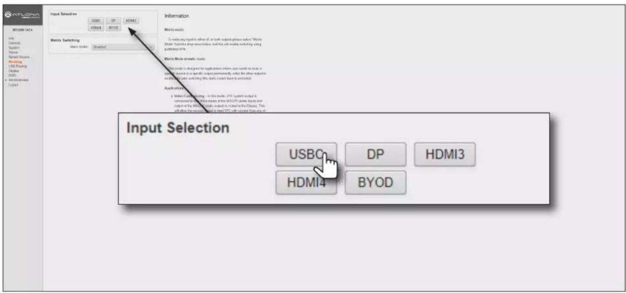
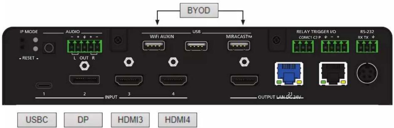
The diagram below, shows each input on the AT-OME-MS52W, and its associated Input Selection button within the web server.
Switching Modes
The AT-OME-MS52W features two switching modes: Matrix Mode and Matrix Mode with static route. Each of these modes will be covered in the following section and are configured using the built-in web server.
Matrix Mode
This mode allows the AT-OME-MS52W to independently switch between any input to any output. Auto switching and display control is disabled in Matrix Mode.
- Login to the web server. Refer to Logging in to the Web Server (page 20) for more information.
- Click Routing in the side menu bar.
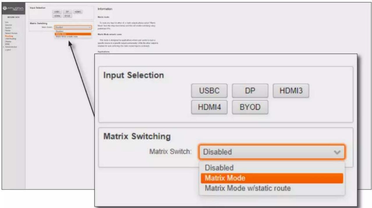
- Click the Switching Mode drop-down list and select Matrix Mode.

IMPORTANT: When the AT-OME-MS52W is set to Matrix Mode, both auto-switching and display control will be disabled.
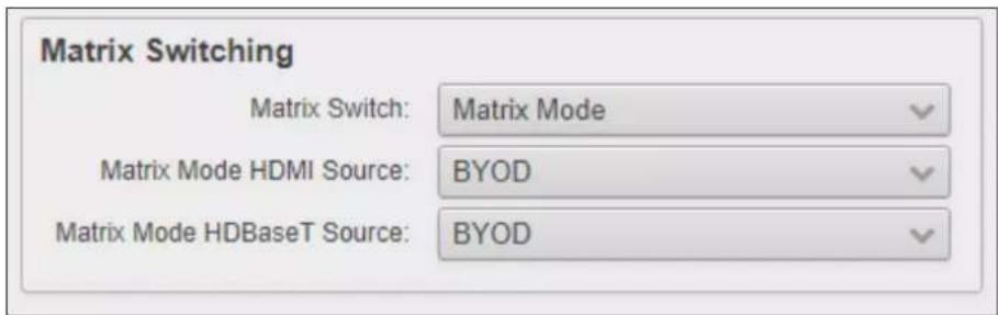
- The Matrix Switching window group now contains the following options:
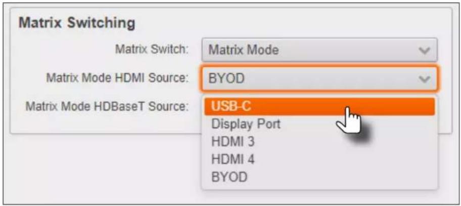
- Click the Matrix Mode HDMI Source drop-down list and select the input to be routed to the HDMI OUT port.
- Click the Matrix Mode HDBaseT Source drop-down list and select the input to be routed to the HDBaseT OUT port.
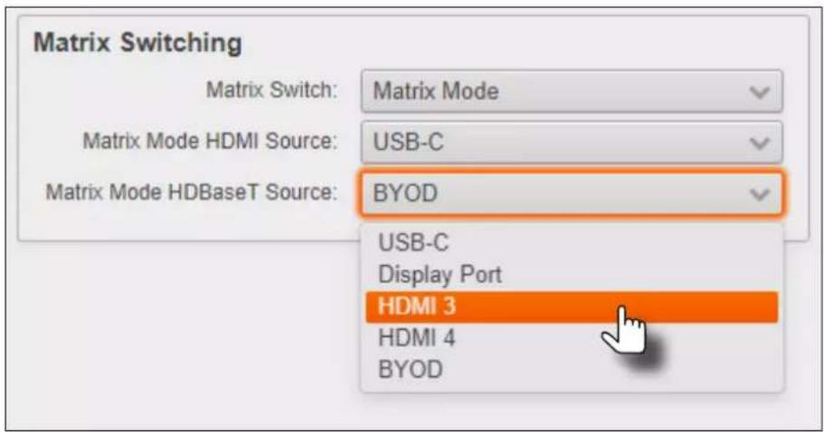
- Matrix Mode configuration is complete.

NOTE: If the input for Matrix Mode HDBaseT Source is not selected, then the input that was selected for the Matrix Mode HDMI Source will be also output on the HDBaseT OUT port.
Matrix Mode w/ Static Route
This mode is desirable when integrating the AT-OME-MS52W with a video conference system and allows for auto switching and display control. In this mode, both static input and output routing are specified. Auto-Switching (page 29) must be enabled. However, the specified static input will be removed from the auto-switching pool. For example, if the HDMI IN 3 port is specified as a static input, then auto-switching will "skip" this port when auto-switching.
- Login to the web server. Refer to Logging in to the Web Server (page 20) for more information.
- Click Routing in the side menu bar.
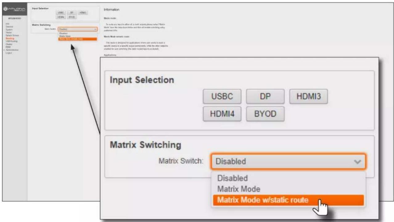
- Click the Matrix Switch drop-down list and select Matrix Mode w/static route.
- The Matrix Switching window group now contains the following options:
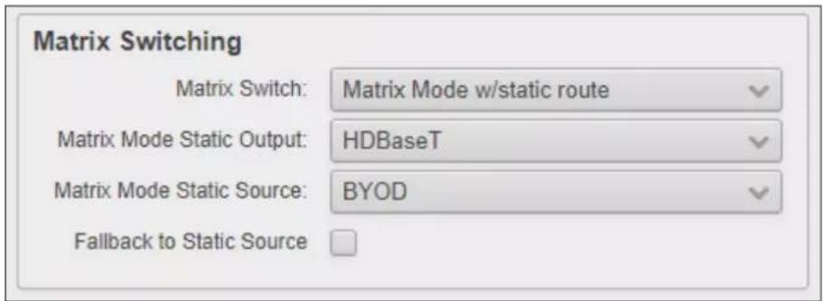
The Fallback to Static Source option is used to set the fallback input. Normally, the input would fallback to BYOD if no source was present. However, checking this box will allow the input to fallback to the source specified in the Matrix Mode Static Source drop-down list.
- Click the Matrix Mode Static Output drop-down list and select the output that will be "static". This is the output that will not change.
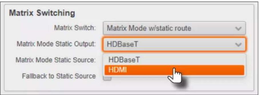
- Click the Matrix Mode Static Source drop-down to select the source that will be assigned as a "static" source. This source will be routed to the output selected in the Matrix Mode Static Output drop-down list.
In this example, the source connected to the Display port input, will be output to the HDMI output port. INPUT 2 (DisplayPort) is the static source and OUTPUT 1 (HDMI) is the static output. This particular configuration will allow the USB-C and both HDMI IN ports to be routed to the HDBaseT OUT port, as needed.
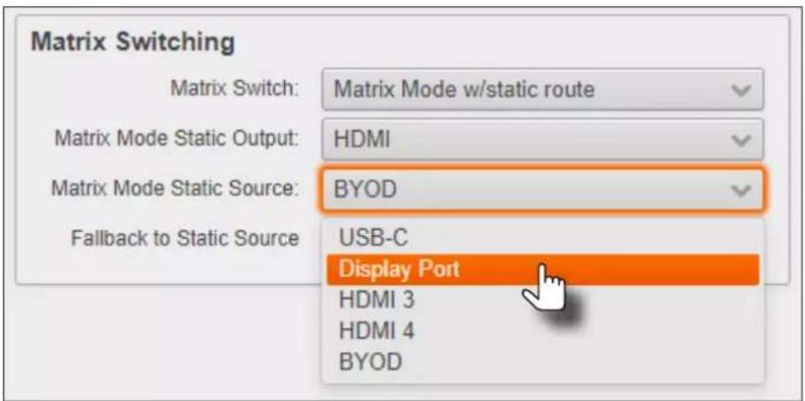
- Matrix with static route configuration is complete.
Auto-Switching
The AT-OME-MS52W provides auto-switching capability, which is enabled by default. This feature will automatically switch the input to the most recently-connected source. If a source is disconnected, then the input will automatically be switched to the previously-connected source.

IMPORTANT: The auto-switching feature is only available when the Switching Mode is set to Matrix mode with static route or Disabled. Refer to Switching Modes (page 25) for more information.
Enabling / Disabling Auto Switching
By default, auto-switching is enabled on the AT-OME-MS52W, allowing the unit to automatically switch between inputs when sources are connected or disconnected. Auto-switching is always enabled when set to Matrix mode with static route and cannot be disabled.
- Login to the web server. Refer to Logging in to the Web Server (page 20) for more information.
- Click Display in the side menu bar.
- Under the Control window group, the AutoSwitch checkbox will be checked, indicating that auto-switching is enabled. If the AutoSwitch checkbox is grayed out, verify that the Switching Mode is set to either Disabled or Matrix mode with static route.
- Click the AutoSwitch checkbox to remove the check mark to disable auto-switching. Note that if the previously active input is no longer available that it will fallback to any available input.

NOTE: The AT-OME-MS52W retains the currently selected input, even after the unit is powered-off then powered-on. The system should re-evaluate the auto switching logic after power on and select an input.
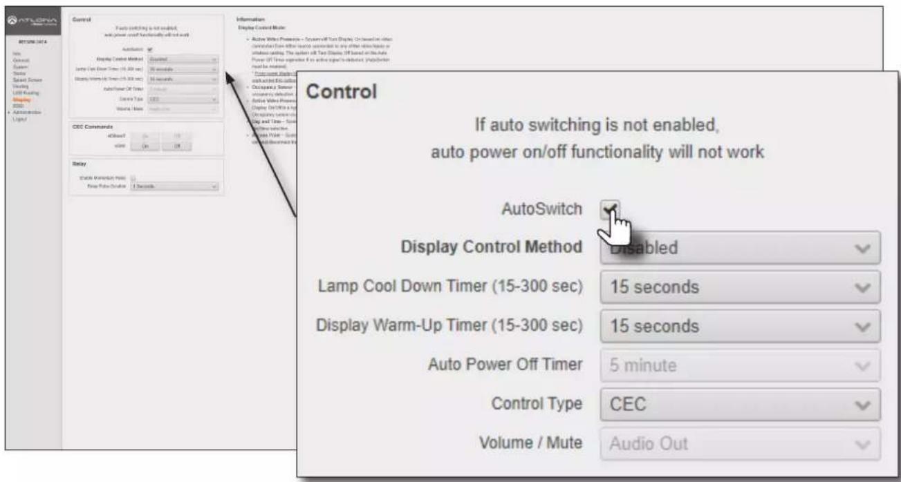
- Auto switching configuration is complete.
USB Modes
The AT-OME-MS52W provides three USB modes: Manual, Follow USB, and Follow Video. Each mode provides different method of selecting the USB host ports. Note that the USB-C port also serves as a host port.
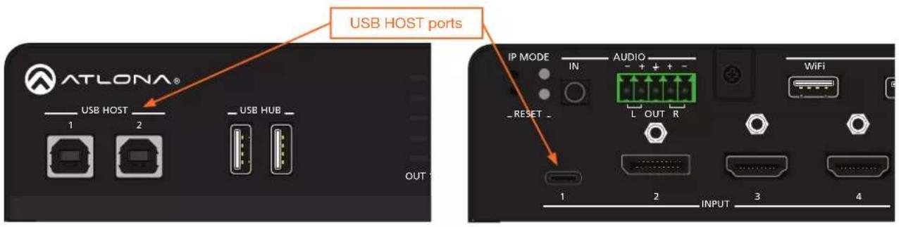
Manual
This is the default mode and provides manual selection of the USB host port to be used, when switching video inputs.
- Connect the host computers to the USB host ports, as desired. Note that it is not required that both USB host ports be connected to host devices.
- Login to the web server. Refer to Logging in to the Web Server (page 20) for more information.
- Click USB Routing in the menu bar.
- Click the USB Routing Mode drop-down list and select Manual.
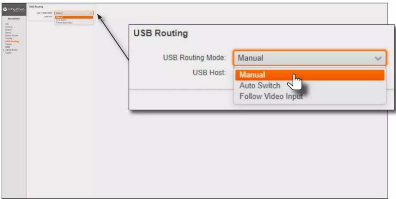
- Click the USB Host drop-down list and select the desired USB port.
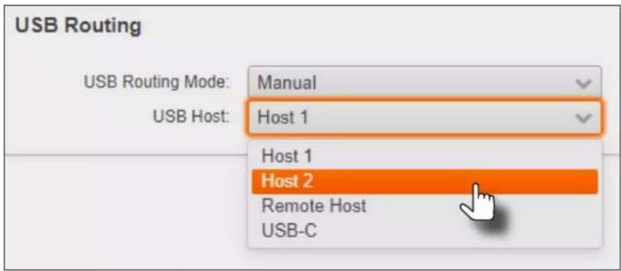
| USB Host Description | |
| Host 1 USB HOST 1 port | |
| Host 2 USB HOST 2 port | |
| Remote Host Uses the USB host port on the HDBaseT receiver | |
| USB-C USB-C port | |
- Manual USB configuration is complete.
Auto Switch
In this mode, the AT-OME-MS52W will detect which USB ports are connected to a host device. If all USB host ports are connected to host devices, then the AT-OME-MS52W will set the last-connected USB host device as the "active" USB host. Use the procedure below to enable Follow USB mode.
- Connect the host computers to the USB host ports, as desired. Note that it is not required that both USB host ports be connected to host devices.
- Login to the web server. Refer to Logging in to the Web Server (page 20) for more information.
- Click USB Routing in the menu bar.
- Click the USB Routing Mode drop-down list and select Auto Switch.
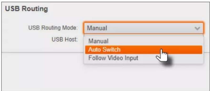
Device Operation
Once set to Auto Switch mode, the AT-OME-MS52W will exhibit the following behavior:
- If only one USB host device is connected to the USB host ports, then the AT-OME-MS52W will use the USB host device connected to that port.
- If another USB host device is connected to a vacant USB host port, then the AT-OME-MS52W will automatically switch to that USB host device.
- If USB 1, USB 2, and USB-C host ports are connected, then the AT-OME-MS52W will switch to the USB port that was connected last.
-
If USB 1, USB 2, and USB-C host ports are connected, and one USB host port is disconnected, then the ATOME-MS52W will automatically switch to the USB host port that was connected last.
-
Auto Switch configuration is complete.
Follow Video Input
In this mode, a video input can be paired with USB 1, USB 2, or a remote USB host port on a receiver. When a video input switch event occurs, the assigned USB host port will follow. Note in this mode that the USB-C port is not considered a host (data) port.
- Connect the host computers to the USB host ports. Note that it is not required that both USB host ports be connected to host devices.
- Login to the web server. Refer to Logging in to the Web Server (page 20) for more information.
- Click USB Routing in the menu bar.
- Click the USB Routing Mode drop-down list and select Follow Video Input.
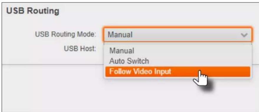
- The factory-default USB Host assignments for each input is shown below.
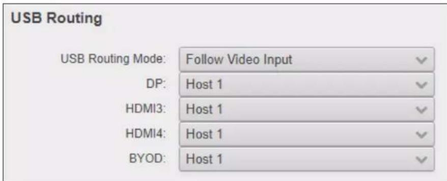
Device Operation
- Click the drop-down list, next to the desired input, to assign the USB host port to the input. In the example below, the HDMI3 (INPUT 3) is being assigned to Host 1 (USB HOST 1).
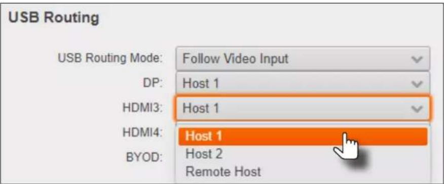
- Configure other inputs as required.
- Follow Video configuration is complete.
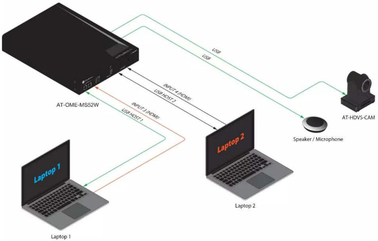
EXAMPLE - HDMI 3 is selected as the active video input and USB HOST 1 is now the active USB host, providing access to Laptop 1, which has access to the speaker/mic and the AT-HDVS-CAM. Black signal lines indicate that the AT-OME-MS52W is not switched to that input.
flowchart
graph TD
    A["AT-OME-MS52W"] -->|USB| B["Laptop 2"]
    A -->|USB HOST 2| C["Laptop 1"]
    A -->|USB HOST 1| D["Laptop 1"]
    B -->|Speaker / Microphone| E["AT-HDVS-CAM"]
    C -->|INPUT 4 (HDMI)| A
    C -->|INPUT 3 (HDMI)| A
    D -->|INPUT 3 (HDMI)| A
The Splash Screen
The splash screen is displayed after the AT-OME-MS52W has completed the boot-up process, and indicates that the unit is ready for use. To view the splash screen, connect an HDMI cable to OUTPUT 1 (HDMI) or OUTPUT 2 (HDBaseT) on the AT-OME-MS52W to the HDMI input of a display.
Customizing Text
- Login to the web server. Refer to Logging in to the Web Server (page 20) for more information.
- Click Splash Screen in the side menu bar.
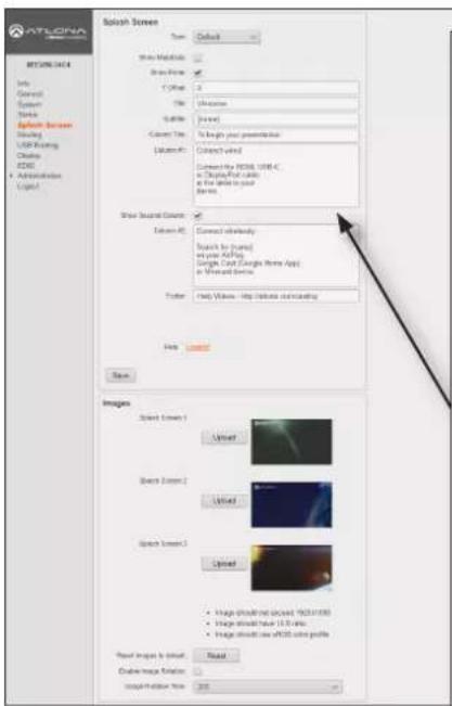
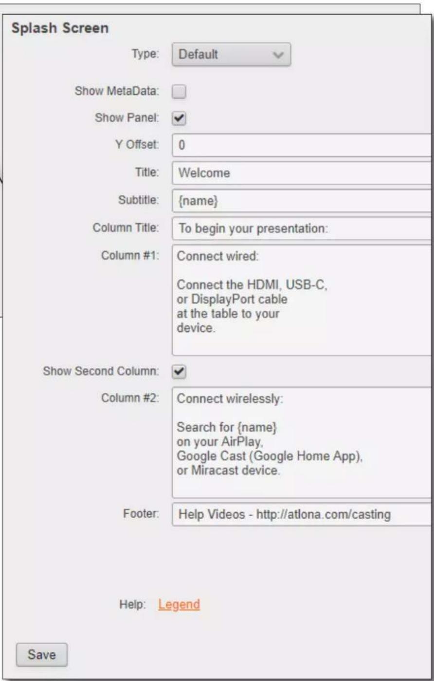
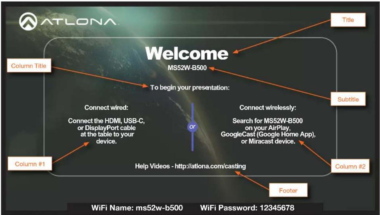
- The Splash Screen window group has several settings. Note that the Column #1 and Column #2 fields provide default instructions on how to connect to the AT-OME-MS52W.
As with any fields in this window group, they can be customized to provide instructions for connecting to the AT-OME-MS52W in a specific environment.
The next page provides an illustration which identifies each of these fields, as they appear
Device Operation
flowchart
graph TD
    A["Welcome"] --> B["MS52W-B500"]
    B --> C["To begin your presentation:"]
    C --> D["Connect wired: Connect the HDMI, USB-C, or DisplayPort cable at the table to your device."]
    C --> E["Connect wirelessly: Search for MS52W-B500 on your AirPlay, GoogleCast (Google Home App), or Miracast device."]
    D --> F["Help Videos - http://atlona.com/casting"]
    E --> G["Footer"]
    F --> H["Column #1"]
    G --> I["Column #2"]
    H --> J["Column Title"]
    I --> K["Title"]
    style C fill:#f9f,stroke:#333
    style D fill:#f9f,stroke:#333
    style E fill:#f9f,stroke:#333
    style F fill:#f9f,stroke:#333
    style G fill:#f9f,stroke:#333
    style H fill:#f9f,stroke:#333
    style I fill:#f9f,stroke:#333
- Refer to the previous page and make any desired changes to each field. Note that the "tag" {name} is present in the Subtitle field, by default. The value of {name} is a system value cannot be changed, as it identifies this specific device: MS52W. However, the {name} tag can be removed from the Subtitle field and replaced with other text.
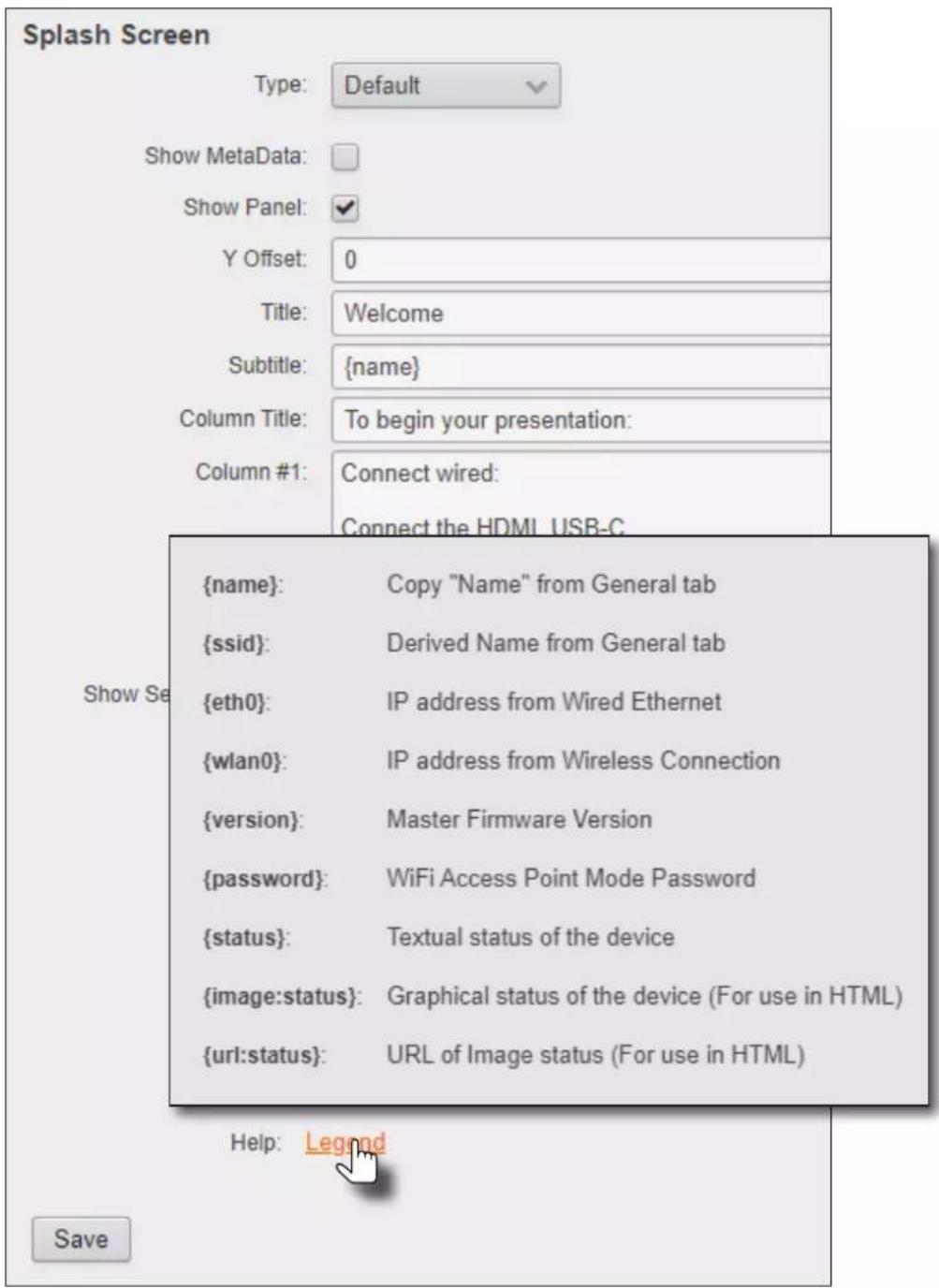
Other tags, and a description of their values, are listed in the table below.
| Tag Description | |
| {name} This is the system | name, and is usually the conference room/classroom name. |
| {ssid} The name of the device when the AT-OME-MS52W is configured as an Access Point. Refer to Access Point Mode (page 45) for more information. | |
| {eth0} The IP address of the AT-OME-MS52W when connected to a network using an Ethernet cable. | |
| {wlan0} The IP address of the AT-OME-MS52W when using a wireless connection. | |
| {version} Displays the Master Firmware version. | |
| {password} Displays the Access Point password, when the AT-OME-MS52W is configured as an Access Point. If configured as an Access Point, this tag will be populated with the selected password. The password can be either static or dynamic. When set to dynamic, this field will be constantly updated. Refer to Access Point Mode (page 45) for more information. | |
| {status} The status of the AT-OME-MS52W. | |
| {image:status} The graph cal status of the device (when using HTML splash screens). | |
| {url:status} The URL of image status (when using HTML splash screens). | |
- Click the Legend link to display a list of these tags at any time.
-
The Y Offset field is used to adjust the horizontal centering of the panel. The default value is 0 (center). Positive values will shift the panel to the right. Negative values will shift the panel to the left. Adjusting the Y Offset does not move the background image of the splash screen.
-
Click the Save button to commit all changes within the Splash Screen window group.
Displaying Metadata
Click the Meta Data checkbox to display metadata information on the splash screen. Metadata includes the name of the unit, model, current date, wired IP address, current firmware version, and some image references used by the AT-OME-MS52W.
- Login to the web server. Refer to Logging in to the Web Server (page 20) for more information.
- Click Splash Screen in the side menu bar, then click the Show Meta Data checkbox. A check mark in this box indicates that the feature is enabled, and metadata will be displayed on top of the splash screen.
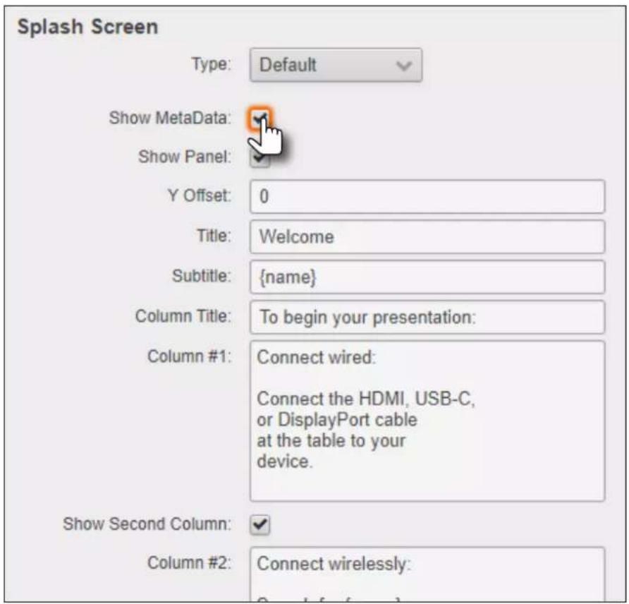
An example of metadata is shown below.
Name: SW52W-B287
Model: SW52W
Date: 03/16/2022
Wired IP: 10.1.0.19
Version: 2.9.4
LED - Grey: /opt/tomcat/webapps/ROOT/static/images/icons/led_grey_small.png
LED - Grey: <image src="{url:led_grey}">
LED - Green: /opt/tomcat/webapps/ROOT/static/images/icons/led_green_small.png
LED - Green: <image src="{url:led_green}">
    LED - Red: /opt/tomcat/webapps/ROOT/static/images/icons/led_red_small.png
    LED - Red: <image src="{url:led_red}">
LED - Status: {image:led_green}
LED - Status: {url:led_green}
Status: Ready
- Click the Save button, at the bottom of the Splash Screen window group, to commit changes. To hide the metadata, uncheck the Show MetaData checkbox and click the Save button.
Device Operation
Displaying the Wireless Password
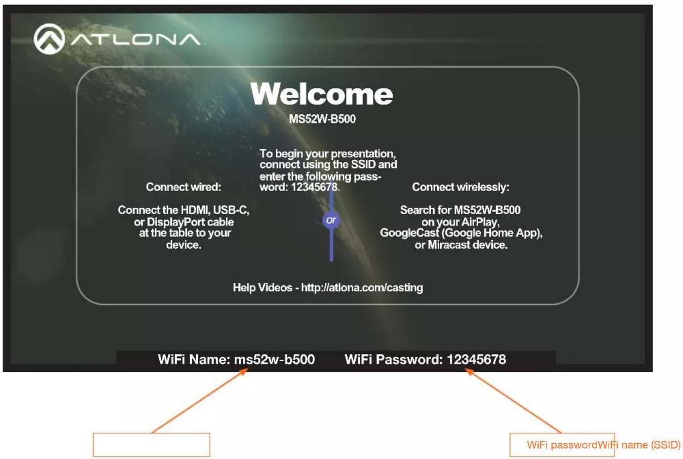
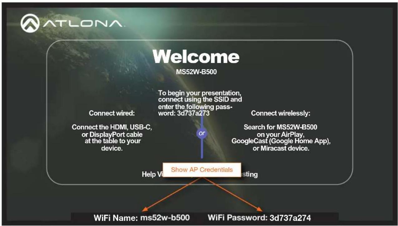
This feature is applicable only when the AT-OME-MS52W is configured as an access point. The wireless password can be displayed as part of any text field on the splash screen, by inserting the {password} tag as part of a text string. For example:
"To begin your presentation, connect using the SSID and enter the following password: {password}.
Note that when the AT-OME-MS52W is configured as an access point, the wireless password will automatically be displayed by default, at the bottom of the screen, as shown below. In addition to the password, the WiFi Name field represents the SSID of the AT-OME-MS52W and is used to identify the unit as an available access point. Refer to Wireless Configuration (page 45) for information on setting up a WiFi connection.
Device Operation
Cycling Background Images
Background image cycling can prevent image persistence, which is the equivalent of image burn-in on CRT and plasma computer monitors.
- Login to the web server. Refer to Logging in to the Web Server (page 20) for more information.
- Click Splash Screen in the side menu bar.
- Under the Images window group, click the Enable Image Rotation checkbox.
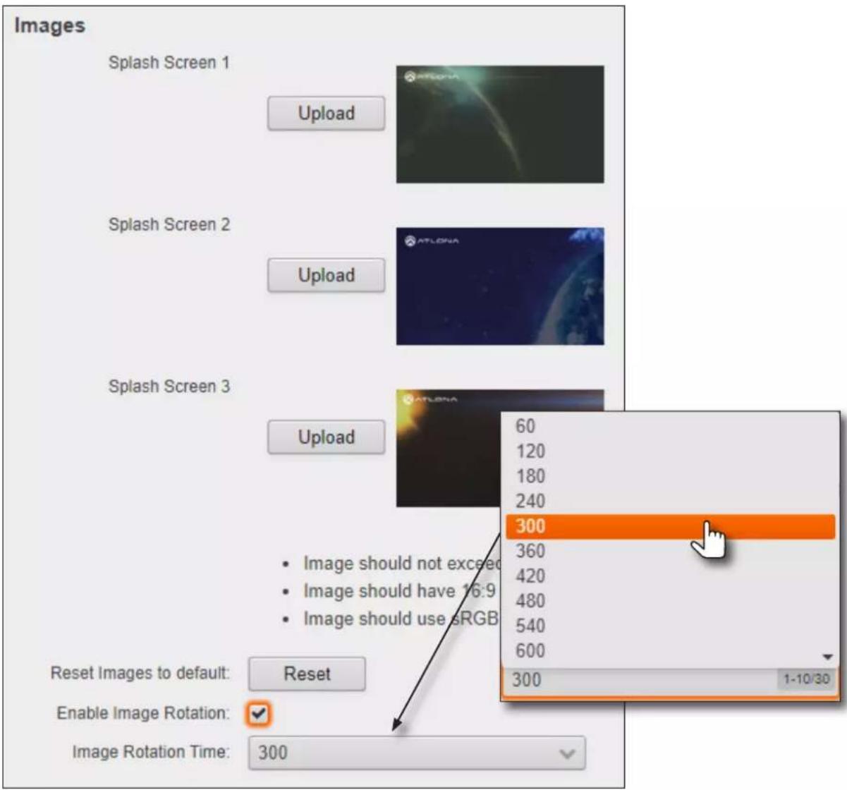
- Click the Image Rotation Time drop-down list to select the desired time interval. Range: 1 - 10 minutes. The default image cycling time is 5 minutes (300 seconds). To disable image cycling, uncheck the Enable Image Rotation checkbox.
Uploading Custom Images
Custom images may be uploaded and used instead of the factory splash screens.

IMPORTANT: Custom images should not exceed 1920 x 1080. All common image types, such as JPG, BMP, PNG, TIF, GIF, are supported.
- Login to the web server. Refer to Logging in to the Web Server (page 20) for more information.
- Click Splash Screen in the side menu bar.
- Under the Images window group, click the Upload button next to the image to be changed.
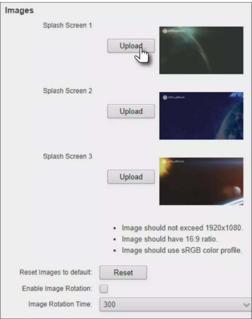
- Select the new image file and click the Open button on the dialog box. If viewing the currently active splash screen, the splash screen will be replaced with the uploaded image.
- Repeat steps 3 and 4, as desired.
HTML Splash Screens
HTML-based splash screens can be used to create content-rich splash screens. This section provides details on creating and uploading an HTML splash screen. Familiarity with HTML is assumed. The AT-OME-MS52W comes with a default HTML splash screen, which can be downloaded from within the web server.
The following table provides a list of supported / unsupported features:
| Feature Supported Not Supported | ||
| HTML5 --- | ● | |
| Relative / absolute references --- | ● | |
| Dynamic images (e.g. animated GIF files)* --- | ● | |
| CSS --- | ● | |
| PHP, JavaScript, ASP (client/server-side processing) --- | ● |
* If a dynamic image is used, only the first frame of the image will be displayed on the splash screen.
Downloading the default splash screen
- Login to the web server. Refer to Logging in to the Web Server (page 20) for more information.
- Click Splash Screen in the side menu bar.
- Under the Splash Screen window group, click the Type drop-down list and select HTML.
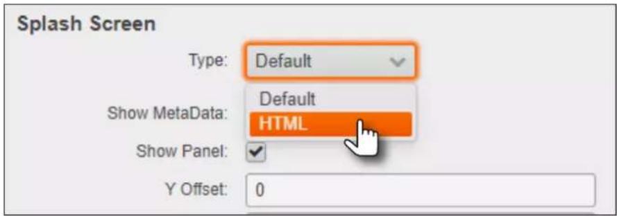
- Click the Download button and save the html.zip file to a desired location on the computer.
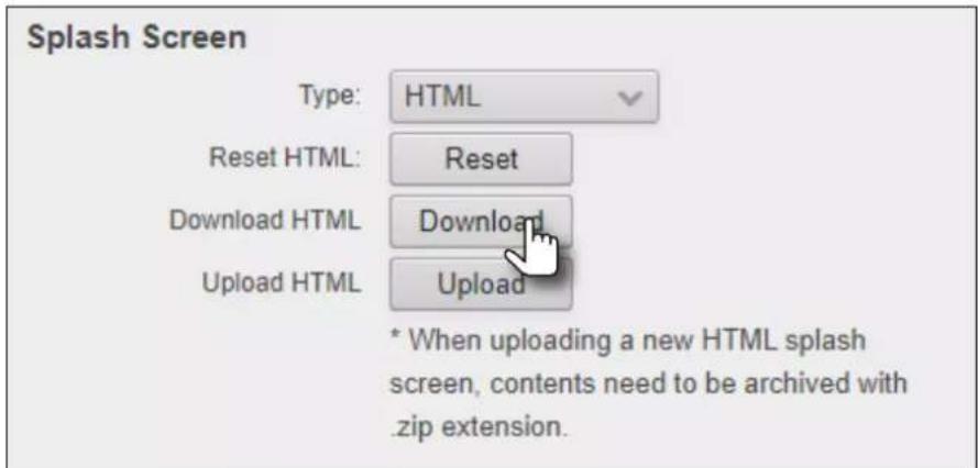
Once the file has downloaded, extract the contents to the desired folder. The included HTML file can be modified, as required, or a different HTML file may be used. The next page provides instructions and guidelines on creating a custom HTML file.
Using a custom HTML file
- Create the HTML file, along with any links to the desired images. The AT-OME-MS52W also comes with a default HTML file (refer to the previous page), and can be used as a starting point when creating a custom HTML splash screen. The example below, is a partial listing of the HTML code within the default HTML file.

NOTE: When creating an HTML splash screen, it must be designed to fit a 1920x1080p display.
<HTML>
<head>
<style>
.container {
    position: relative;
}
.bottomleft {
    position: absolute;
    bottom: 64px;
    left: 64px;
    font-size: 25px;
}
.bottomright {
    position: absolute;
    bottom: 64px;
    right: 64px;
    font-size: 25px;
}
.icon {
    width: auto;
    height: 35px;
    vertical-align: middle;
}
.OutlineText {
    font: Tahoma, Geneva, sans-serif;
    font-size: 64px;
    color: white;
text-shadow:
...
...
}
...
</HTML>
- Save the file as index.html template. Do not add a file extension.
- Combine the index.html_template file along with all required external images/files into a .zip file called html.zip.

IMPORTANT: The index.html_template file must reside in the root directory, within the html.zip file. Other files (.css, images, etc.) can be placed in folders, if desired, or can also be left in the root directory.
The file structure for the default html.zip file, located on the AT-OME-MS52W, is as follows:
airplay.png
cast.png
chrome.png
devices.png
index.html_template
wifi.png
windows.png
- Login to the web server. Refer to Logging in to the Web Server (page 20) for more information.
- Click Splash Screen in the side menu bar.
- Under the Splash Screen window group, click the Type drop-down list and select HTML.
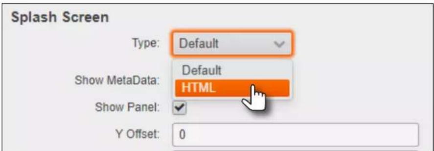
- Click the Upload button.
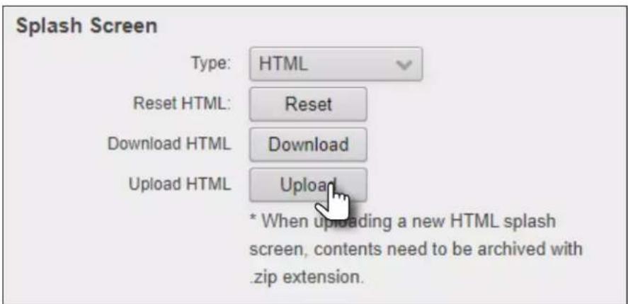
- Select the html.zip file, then click Open, to upload the file to the AT-OME-MS52W.
- Click the Save button, at the bottom of the Splash Screen window group, to commit changes.
Resetting the HTML Splash Screen

IMPORTANT: The Reset (Reset HTML) button will delete any loaded HTML data and replace it with the default HTML page that comes with the AT-OME-MS52W.
- Login to the web server. Refer to Logging in to the Web Server (page 20) for more information.
- Click Splash Screen in the side menu bar.
- Click the Type drop-down list and select HTML.
- Under the Splash Screen window group, click the Reset button.
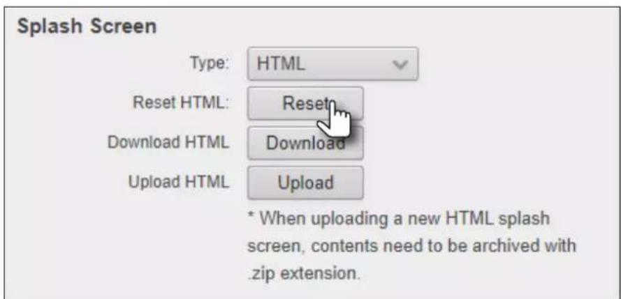
Wireless Configuration
The AT-OME-MS52W features a wireless gateway, providing convenient Wi-Fi® connectivity to iOS, Android, Mac, Chromebook, or Windows-based devices. In addition, the AT-OME-MS52W can be configured as a wireless access point (AP). The addition of a built-in firewall provides filtering of outbound traffic from WAP to Ethernet.
Access Point Mode
When configured as an Access Point (AP), wireless devices can be connected to the AT-OME-MS52W.
- Login to the web server. Refer to Logging in to the Web Server (page 20) for more information.
- Click Administration > Networking in the side menu bar.
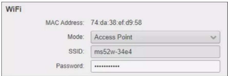
- Under the WiFi window group, click the Mode drop-down list and select Access Point.
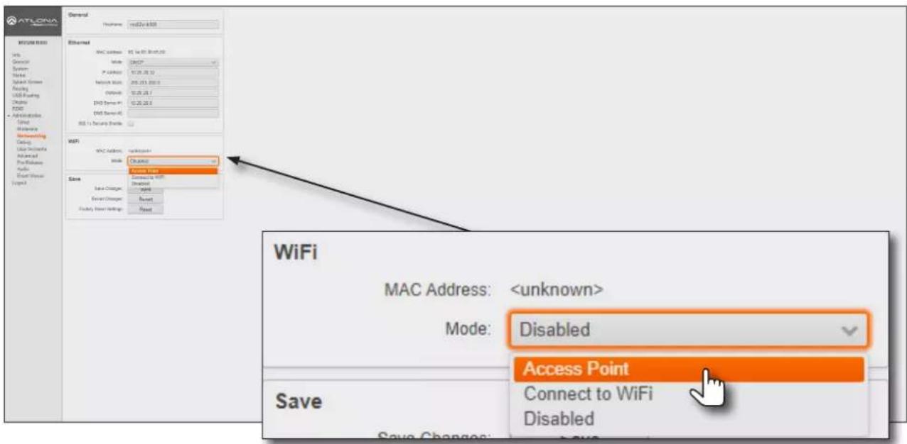
-
The name of the wireless network will appear in the SSID field. This name is identical to the text in the Derived field, under the General page (page 80). To change the SSID, go to the General page and modify the Name field.
-
Enter the password in the Password field. The password will be required by clients connecting to the AT-OME-MS52W. The default password is 12345678. Make sure to clear this value and provide a secure password.

IMPORTANT: If no password is supplied in Access Point mode, then any client will be able to connect to the AT-OME-MS52W without credentials. Make sure this is the desired operation before continuing. Also, if the Acces Point is not secured, then the Miracast Infrastructure will not function, as it requires encryption of traffic.
Device Operation
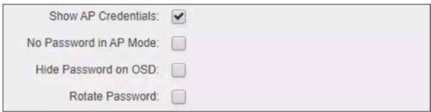
- The Show AP Credentials checkbox is enabled by default. Enabling this feature will display the WiFi Name and WiFi Password fields to be displayed on the splash screen, as shown below. Uncheck this box to hide the name and password.
flowchart
graph TD
    A["Connect wired: Connect the HDMI, USB-C, or DisplayPort cable at the table to your device."] --> B["To begin your presentation, connect using the SSID and enter the following password: 3d737a273"]
    C["Connect wirelessly: Search for MS52W-B500 on your AirPlay, GoogleCast (Google Home App), or Miracast device."] --> D["or"]
    E["Help Wi"] --> F["Show AP Credentials"]
    F --> G["WiFi Name: ms52w-b500"]
    F --> H["WiFi Password: 3d737a274"]
- Check the No Password in AP Mode checkbox if no password credential is desired.
- Click the Hide Password on OSD checkbox to prevent the WiFi Password field from being displayed.
- Click the Rotate WiFi Password checkbox to allow the AT-OME-MS52W to generate a new random password.
This feature can be used to provide an extra level of security. Dynamically rotating the password decreases the risk that unauthorized clients will not have access to the AT-OME-MS52W, if the current password is "leaked" or observed on the splash screen, outside of a meeting space or other environment. It should be noted that the system will not change the password, once content is being presented, and will wait until the presentation is finished to begin password rotation. Check the Hide Rotated Password checkbox to hide rotated passwords.
- Click the Password Rotation Interval drop-down list to select the rotation time interval for new password generation. The default setting is 1 hour.

Device Operation
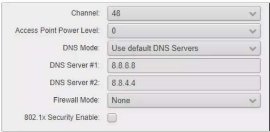
- Enter the wireless channel number in the Channel field. Channels 1 through 11 are 2.4 GHz channels. Channels 36 and above are 5 GHz channels. Contact the network administrator if necessary.
- Click the Access Point Power Level drop-down list to select the desired power level of the WiFi USB antenna. Available values are integers 0 through 13. Lower values will reduce transmission power of the USB WiFi antenna, thus limiting the range of the Access Point on the AT-OME-MS52W.
- If a different set of DNS servers are desired, click the DNS Mode drop-down list and select the desired mode:
| Feature Description | |
| Use default DNS Servers Uses the default DNS provided by the DHCP server. This is the default setting. | |
| Inherit from wired Network Uses the same DNS provided by the wireless network. | |
| Static | Enter the primary and secondary DNS addresses in theDNS Server #1andDNS Server #2fields, respectively. |
- The Firewall Mode drop-down list allows filtering of outgoing network traffic, from/to a network that is connected to the LAN port on the AT-OME-MS52W. Refer to Firewall Mode (page 48) for more information.
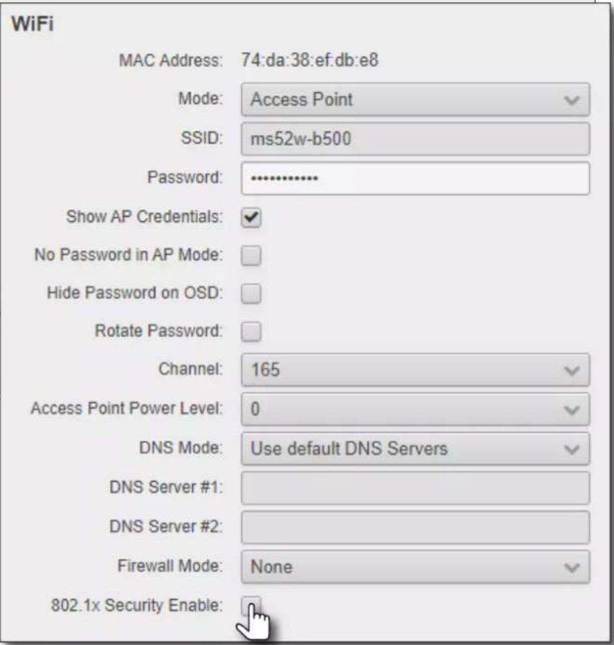
- Click the 802.1x Security Enable checkbox to enable 802.1x. Refer to 802.1X Authentication (page 53) for more information.
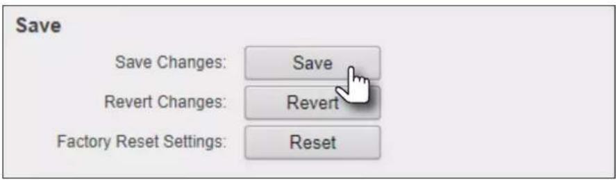
- To commit changes, click the Save button, located under the Save window group.
Device Operation
Firewall Mode
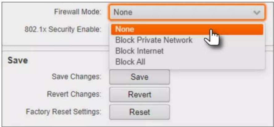
This feature allows filtering of outgoing network traffic, from/to a network that is connected to the LAN port on the AT-OME-MS52W. The AT-OME-MS52W provides the following firewall modes: Block Private Network, Block Internet, Block All, and None. If this feature is not desired, then the following steps can be skipped. The firewall can be configured or disabled at any time. The default setting is None.
- Login to the web server. Refer to Logging in to the Web Server (page 20) for more information.
- Click Administration > Networking in the side menu bar.
- Under the WiFi window group, click the Mode drop-down list and select Access Point.
- Click Firewall Mode drop-down list and select the desired option.
| Setting Description | |
| None (default) Select this | option to disable the firewall on the AT-OME-MS52W and allow all outgoing network traffic. |
| Block Private Network This option will globally block all private IP address ranges and traffic to the internal network on the LAN, except Internet access. | |
| Block Internet Allows wireless access to the AT-OME-MS52W and communication with the internal network, but prevents Internet access (Google, YouTube, etc). | |
| Block All All outbound network traffic is blocked. Wireless traffic to the AT-OME-MS52W is permitted, but no wireless data will be sent to the Ethernet port of the AT-OME-MS52W. | |
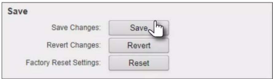
- Click the Save button, under the Save window group, to commit changes.
Connect to WiFi Mode
Use this mode to connect the AT-OME-MS52W to another wireless network.
- Login to the web server. Refer to Logging in to the Web Server (page 20) for more information.
- Click Administration > Networking in the side menu bar.
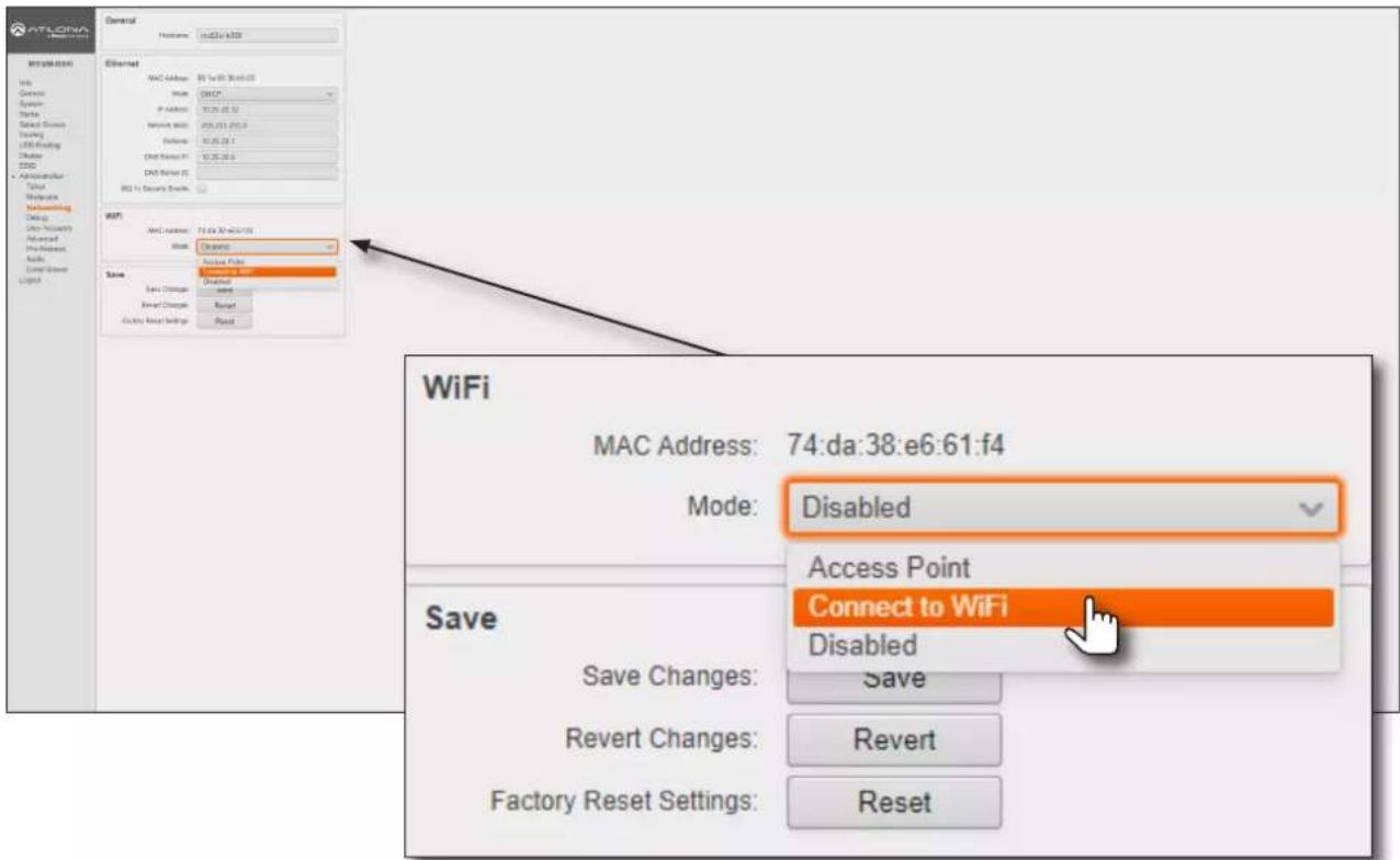
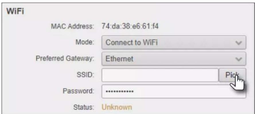
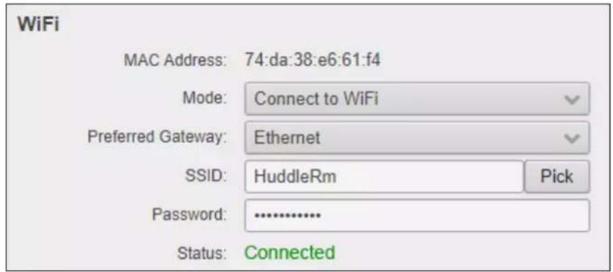
- Under the WiFi window group, click the Mode drop-down list and select Connect to WiFi.
-
Click the Preferred Gateway drop-down list and select the desired gateway. When set to Connect to WiFi mode, the AT-OME-MS52W can only be accessed though the same network, over Ethernet or WiFi, not both. For example, if Ethernet is selected, then the AT-OME-MS52W can only be accessed from the same network over Ethernet. However, it should be noted that casting is supported on both interfaces, simultaneously.
-
Click the Pick button to display a listing of available WiFi networks.
Device Operation
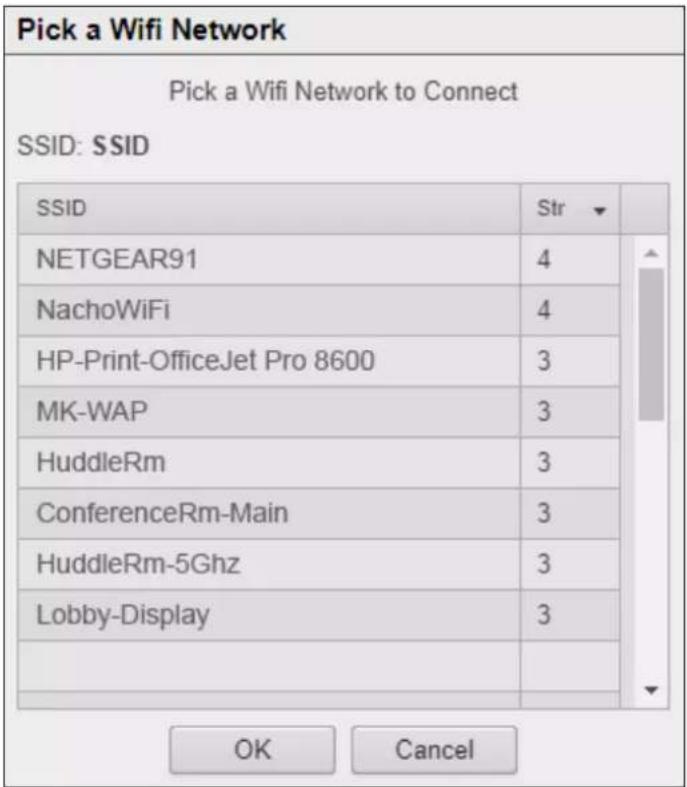
- Click the desired WiFi network from the list and click the OK button to accept the selection or click Cancel to return to the WiFi window group.
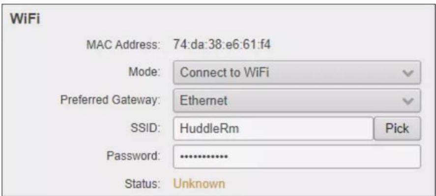
- Enter the password for the wireless network in the Password field.
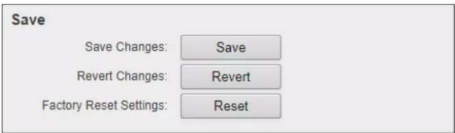
- Click the Save button near the bottom of the screen to commit changes.
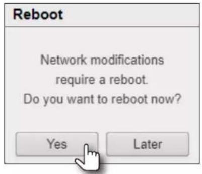
- The system will prompt to be rebooted, as shown below. Click Yes to perform a reboot. To reboot at a later time, click the Later button.
Once the connection has been established, the Status field will display Connected, as shown below.
The following table provides a description of status messages.
| State Description | |
| Connected The AT-OME- | MS52W is connected to the wireless network. |
| Not Connected Unsuccessful connection. Check to make sure the password was entered correctly. This state will also occur if the wireless network, to which the AT-OME-MS52W is connected, is taken offline. | |
| Unknown The network state is unknown. This message is displayed if the AT-OME-MS52W has not been configured to connect with a wireless network. | |
Changing the SSID
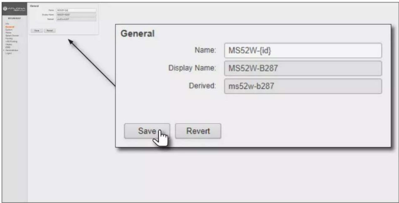
By default, the SSID of the AT-OME-MS52W is set to the following identifier: ms52w-{id}. The first five digits are the last five characters of the product SKU. The {id} tag holds the last four digits of the MAC address.
This identifier is held in the Name field, under the General tab. The AT-OME-MS52W copies the Name field to the Derived field, converting the characters to lowercase. The Derived field then becomes the SSID.
- Login to the web server. Refer to Logging in to the Web Server (page 20) for more information.
- Click General in the side menu bar.
- Under the General window group, change the Name field to the desired name.
- Click the Save button to commit changes.
802.1X Authentication
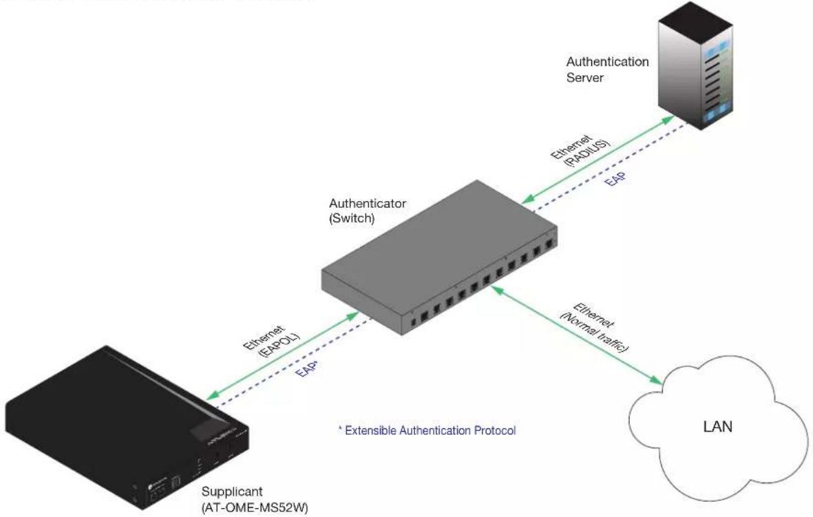
802.1X is a server-based port authentication protocol which restricts unauthorized (rogue) clients from connecting to a Local Area Network through a public port. In its simplest form, 802.1X usually involves three parties: supplicant (client device), authenticator (Ethernet switch), and an authentication server. Before the device is permitted on the network, port communication is restricted to Extensible Authentication Protocol over LAN (EAPOL) traffic. If the device passes the authentication process, then the authentication server notifies the switch, allowing the client to access the LAN. A full explanation of the 802.1X protocol is beyond the scope of this manual. However, the illustration below shows the basic architecture.
flowchart
graph TD
    A["Supplicant (AT-OME-MS52W)"] -->|Ethernet (ERPOL)| B["Authenticator (Switch)"]
    B -->|Ethernet (RADIUS)| C["Authentication Server"]
    B -->|Ethernet (Normal traffic)| D["LAN"]
    style A fill:#000,stroke:#fff,color:#fff
    style B fill:#999,stroke:#000,color:#fff
    style C fill:#ccc,stroke:#000
    style D fill:#ccc,stroke:#000
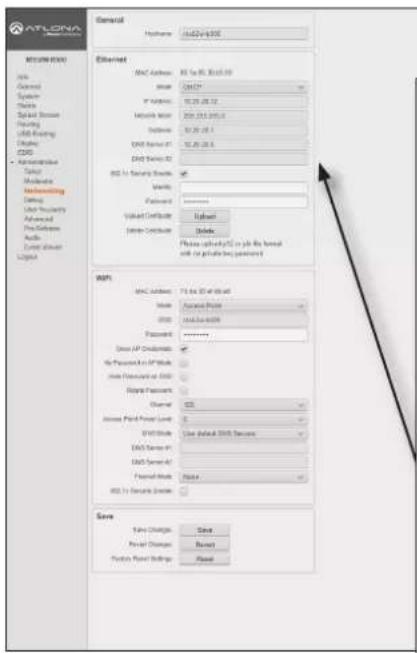
Ethernet Connections
- Login to the web server. Refer to Logging in to the Web Server (page 20) for more information.
- Click Administration > Networking in the side menu bar.
- Make sure the Ethernet connection is working properly.
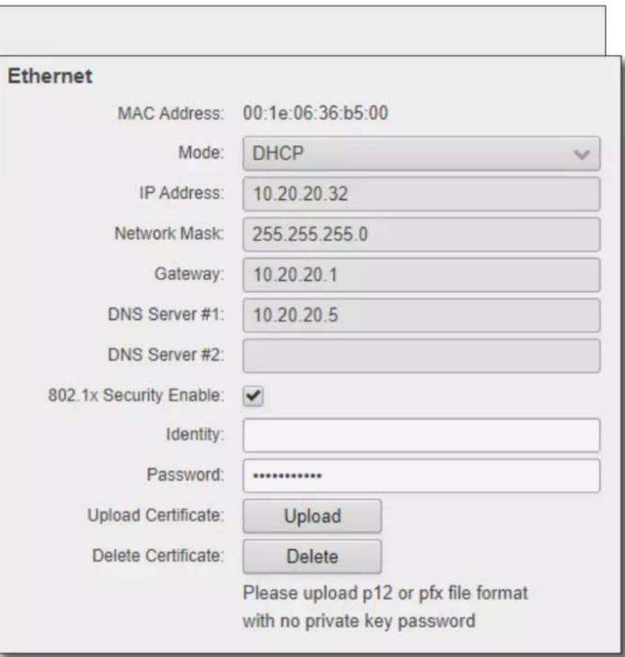
- Under the Ethernet window group, click the 802.1x Security Enable check box.
Ethernet
| MAC Address: 00:1e:06:36:b2:87 | |
| Mode: DHCP | |
| IP Address: 10.20.50.41 | |
| Network Mask: 255.255.255.0 | |
| Gateway: 10.20.50.1 | |
| DNS Server #1: 10.20.20.5 | |
| DNS Server #2: | |
| 802.1x Security Enable: | |
Device Operation
- Enter the identity of the authentication server in the Identity field. EAP uses this field to identify the correct authentication server which will process the credentials. For example, if foo@authserv.com is entered, then this identifies AUTHSERV as the RADIUS (authentication) server.
- Enter the password in the Password field.
- Click the Upload button to select and upload the certificate.
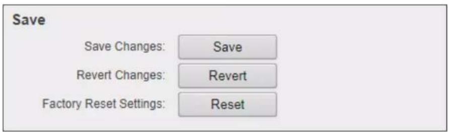
- Under the Save window group, click the Save button to commit changes.
WiFi Connections
- Login to the web server. Refer to Logging in to the Web Server (page 20) for more information.
- Click Administration > Networking in the side menu bar.
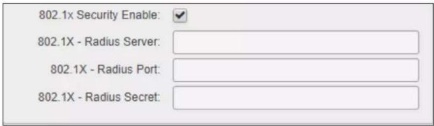
- Under the WiFi window group, click the 802.1x Security Enable check box.
- Enter the server, port number, and the secret, in the Radius Server, Radius Port, and Radius Secret fields, respectively.
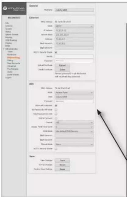
- Click the Save button, under the Save window group, to commit changes.
Casting
The AT-OME-MS52W interface provides the ability to transmit ("cast") the screen of any iOS ^ , Android ^ , macOS ^ , Chromebook, or Windows device over Wi-Fi, without having to install a separate application or driver. The AT-OME-MS52W can serve as an integrated, dual-band access point, or be networked into an existing Wi-Fi installation.

IMPORTANT: Several apps have been known to trigger HDCP, even if the content is unprotected. In these cases, the AT-OME-MS52W will be unable to decode and present the content.
iOS Devices
AirPlay is only supported on iOS 10 or higher.
- Select the BYOD input on the AT-OME-MS52W.
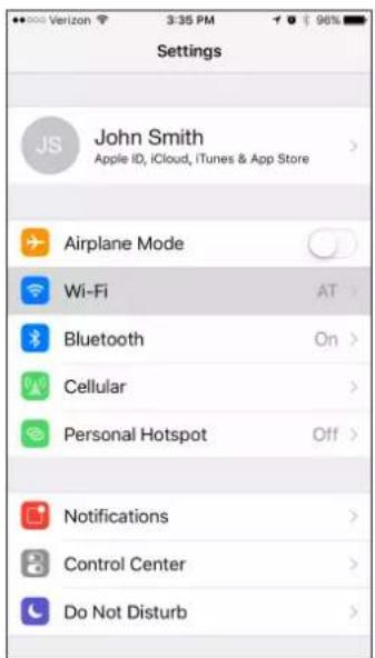
- On the iOS device, go to Settings > Wi-Fi.
- Select the network to which the AT-OME-MS52W is connected or join its access point. The example below shows the AT-OME-MS52W in Connect to WiFi mode. Refer to Connect to WiFi Mode (page 49) for more information.
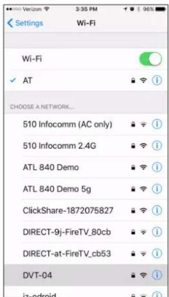
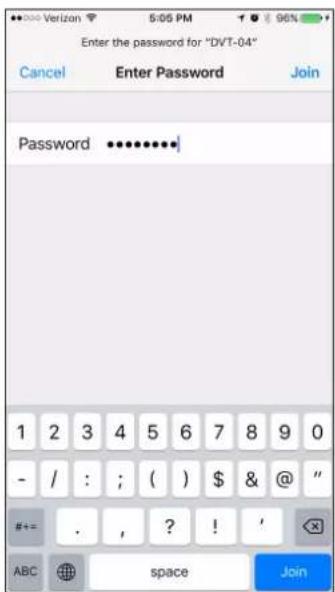
iOS 10 iOS 11.0.3 or later
- Once connected, swipe-up on the bottom of the iOS device to display the Control Center.
- Tap the AirPlay Mirroring option to display a list of available AirPlay devices.
Note that if the iOS device is running 11.0.3 or later, the AirPlay option has been changed to Screen Mirroring. Tap the SSID from the list of devices.
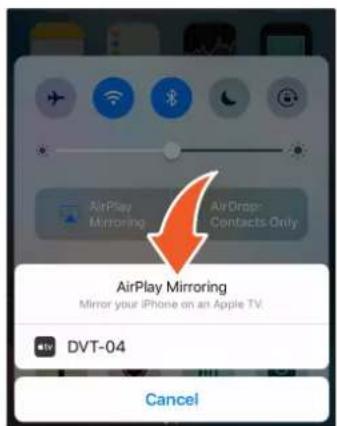
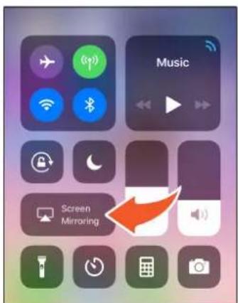
Device Operation
- Tap the SSID from the list of devices.
- Close the Control Center by either swiping down or pressing the Home button.
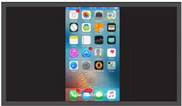
- The image of the iOS device will now appear on the connected display.
Note that depending upon the application, the image on the screen can be rotated. For example, when using the camera app, if the iOS device is rotated 90 degrees, then the image on the screen will also be rotate 90 degrees.
- Close the Control Center by either swiping down or pressing the Home button.
OS X Devices
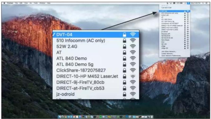
AirPlay ^® is only supported on Mountain Lion 10.8 or later. To determine if AirPlay is supported on the system being used, click System Preferences > Displays. If the “Show mirroring options in the menu bar when available” checkbox is not displayed, then AirPlay is not supported.
- Click the Wi-Fi icon in the menu bar and select the network to which the AT-OME-MS52W is connected.
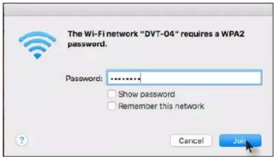
- Enter the password for the Wi-Fi network, then click the Join button.
Device Operation
AirPlay can be used to either mirror or extend the Mac display.
- Mirroring
Click the AirPlay icon in the menu bar and select the desired display to be mirrored.
- Extending
Click the AirPlay icon and select "Use As Separate Display" from the list of displays, to extend the Desktop to another display.
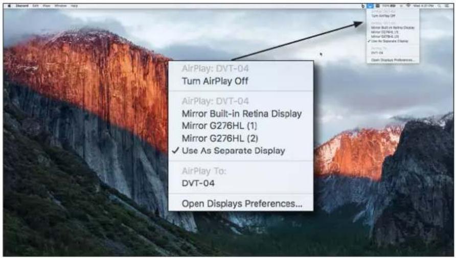
- Turning Off AirPlay
Click the AirPlay icon and select "Turn AirPlay Off".
Device Operation
Microsoft Miracast
Miracast is a wireless protocol that allows content to be transmitted from laptops and other mobile devices to displays. The latest release of Microsoft Windows® 10 supports Miracast.
Displaying Miracast devices can be done in more than one way. Three methods are discussed below. The first method is the most direct method.
Method 1
- Press 📋 + K keys, simultaneously.
- The list of available devices will be displayed on the right-hand side of the screen. Select the AT-OME-MS52W hostname from the list.
Method 2
- Right-click on the Windows Desktop and select Display Settings from the pop-up menu.
- In the right-hand column, scroll down, then click Connect to a wireless display.
Google Chrome
- Make sure both the AT-OME-MS52W and the "casting" computer are on the same network.
- Launch Google Chrome.
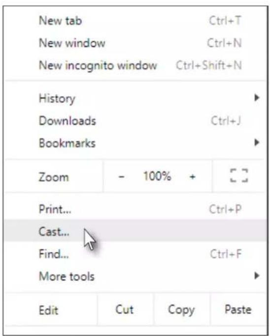
- Click the : icon, in the upper right corner of the Chrome browser.
- Click the Cast... option from the drop-down menu.
- Select the hostname of the AT-OME-MS52W from the Cast to menu.
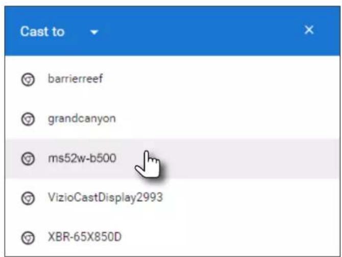
Device Operation
Chrome will immediately begin casting to the AT-OME-MS52W.
- Adjust the volume (if audio is present), by clicking and dragging the slider control. In addition, either Remote screen or Both screens can be selected from the Show fullscreen videos on drop-down list.
- Click the x in the upper-right corner of the Casting tab to dismiss this dialog.
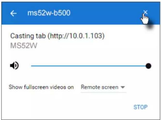
When Chrome is casting, the 📋 icon will appear in the upper-right portion of the menu bar. Clicking this icon will display the Casting tab dialog.
In addition, a blue rectangle will be displayed in the browser tab, which is sharing ("casting") the content to the AT-OME-MS52W. If the browser tab is closed, then the casting process will be terminated.
- Click STOP to discontinue casting to the AT-OME-MS52W.
Audio Management
By default, the AT-OME-MS52W will use the digital audio (if present) from the USB-C IN, DisplayPort, or HDMI ports and output the audio over the HDMI OUT, HDBaseT OUT, and AUDIO OUT ports. However, an external analog source can also be used. When configured, the analog audio source will replace the digital audio on the selected input, and will be heard on the HDMI OUT, HDBaseT OUT, and AUDIO OUT ports.
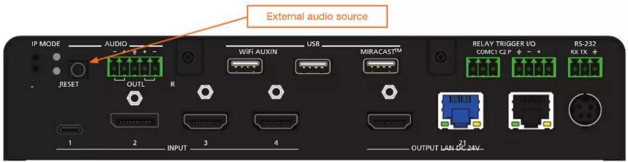
Using External Audio Sources
- Connect an unbalanced audio source to the AUDIO IN port on the rear panel. This port accepts a 3.5 mm mini-stereo cable.
- Login to the web server. Refer to Logging in to the Web Server (page 20) for more information.
- Click Administration > Audio in the side menu bar.
- Click the drop-down list of the desired input and select the audio input. In the example below, Analog is being selected from the HDMI 4 drop-down list. This will replace the digital audio heard on the output (if any), with the analog audio source.
To use the digital audio from the HDMI source, select Digital from the HDMI 4 drop-down list.
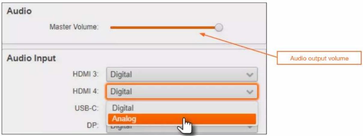
Controlling Audio Output Volume
-
Login to the web server. Refer to Logging in to the Web Server (page 20) for more information.
-
Click Administration > Audio in the side menu bar.
-
Under the Audio window group, click and drag the volume slider to the desired output level. This applies to both digital and analog (external) audio sources.
AirPlay Bluetooth Discovery
The AT-OME-MS52W supports Bluetooth®-assisted device discovery. An optional Bluetooth adapter is required, but not included. Atlona recommends Plugable and Kinivo Bluetooth 4.0 adapters.

IMPORTANT: Bluetooth discovery is applicable only to Apple devices and is used for device discovery on networks, such as corporate networks, where mDNS is not permitted.
Bluetooth discovery behaves as a type of "beacon", indicating the available AT-OME-MS52W units within the local vicinity of an AirPlay device.
- Connect the Bluetooth adapter to the AUX port on the AT-OME-MS52W.
- Login to the web server. Refer to Logging in to the Web Server (page 20) for more information.
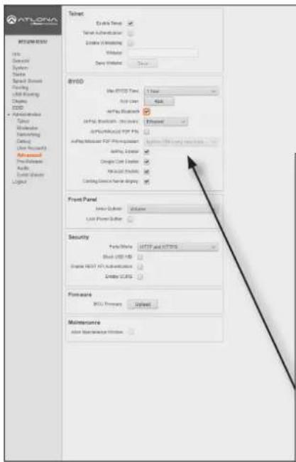
- Click Administration > Advanced in the side menu bar.
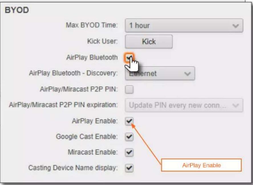
- Under the BYOD window group, click the AirPlay Bluetooth checkbox. If this checkbox has a check mark in it, then the feature is enabled. Also, make sure that the AirPlay Enable checkbox is checked.
- Go to the AirPlay device and activate Screen Mirroring. The AT-OME-MS52W will now be displayed in the Screen Mirroring device list.

NOTE: If the AT-OME-MS52W is beyond the range defined by the Bluetooth specification, then the device will not be displayed in the Screen Mirroring list. When pairing, make sure to be as close to the AT-OME-MS52W as possible.
AirPlay / Miracast P2P PIN Codes
The AT-OME-MS52W can be configured to prompt for a PIN code, before a BYOD device connects with either AirPlay or Miracast P2P. When the this option is enabled, a PIN code will be displayed on the screen when an AirPlay or Miracast device attempts to connect to the AT-OME-MS52W. Refer to the IT Deployment Guide for definitions of Miracast P2P (Peer-to-Peer) and Miracast over Infrastructure.

NOTE: The PIN code will randomly change every five minutes, by default. This value can be set from 10 seconds to five hours. This provides a level of security, preventing unauthorized users from accessing the AT-OME-MS52W. Android ^™ devices do not support PIN code security.
- Login to the web server. Refer to Logging in to the Web Server (page 20) for more information.
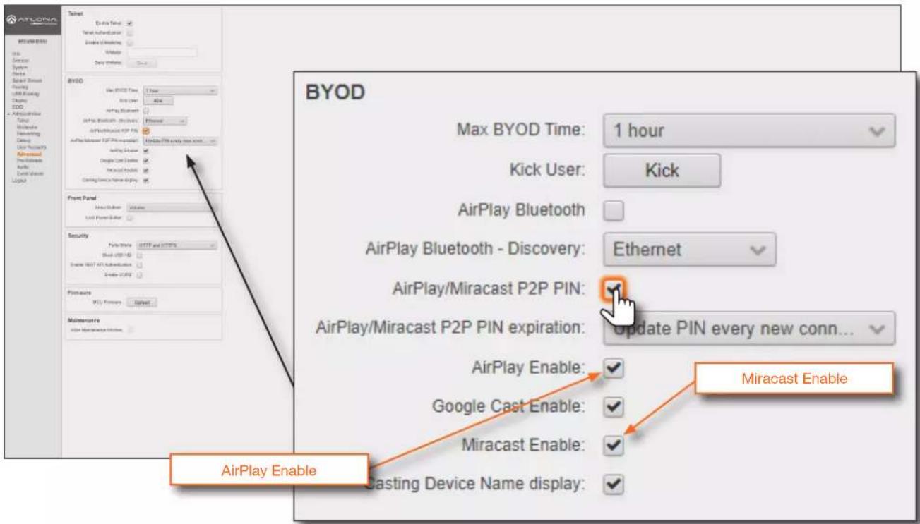
- Click Administration > Advanced in the side menu bar.
- Click the AirPlay Enable and Miracast Enable checkboxes, as required by the casting device.
- Under the BYOD window group, click the Airplay/Miracast P2P PIN checkbox. If this checkbox has a check mark in it, then the feature is enabled.
- The following message box will be displayed. Click the Ok button.
Restart AirPlay/Miracast/Google Cast
AirPlay/Miracast P2P PIN modifications require a restart of AirPlay/Miracast/Google Cast and wireless services please wait a few minutes before casting again.
Device Operation
- Connect the AirPlay/Miracast P2P device to the AT-OME-MS52W. Refer to Wireless Configuration (page 45) for more information.
- Begin casting to the AT-OME-MS52W. When the device attempts to connect to the AT-OME-MS52W, a PIN code will be displayed on the screen that is connected to the device. Refer to the illustration on the next page, if necessary.
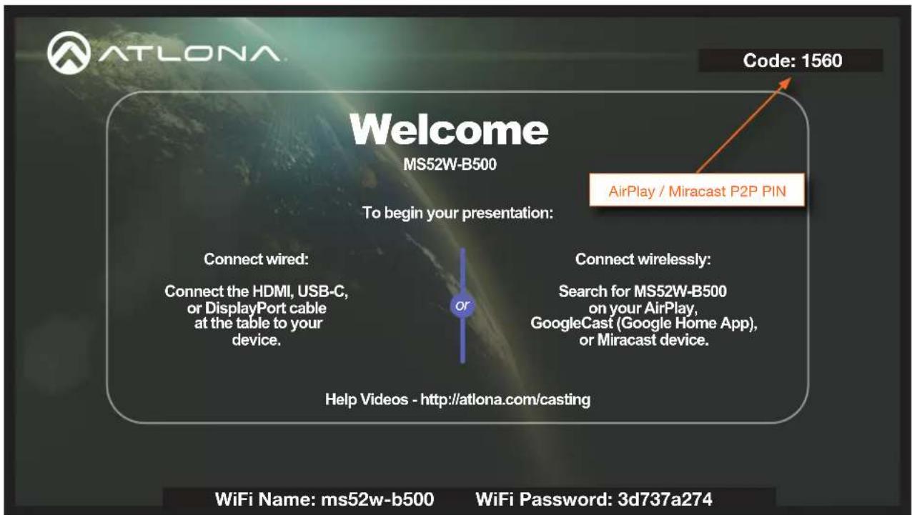
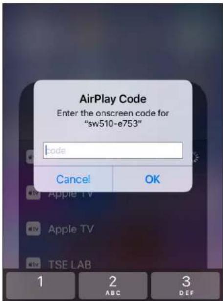
- Enter the four-digit PIN code in the dialog box on the device and press OK. The PIN code will be displayed only for about 10 seconds. If the PIN code is not entered within the time interval, then the PIN code will be removed from the screen. The example below, shows an AirPlay device prompting for the PIN code. Clicking Cancel in the AirPlay Code dialog box will reconnect the AirPlay device to the AT-OME-MS52W and generate a new PIN code.
Changing the PIN Timeout
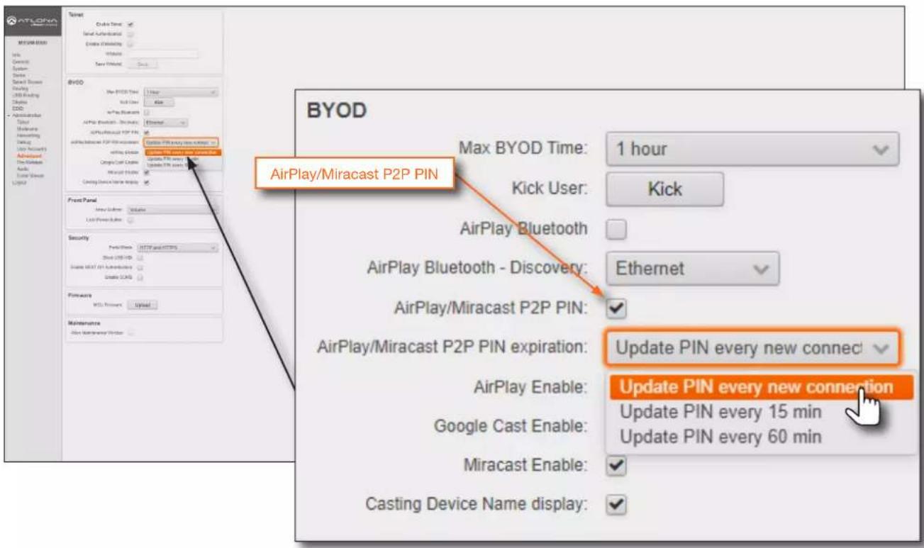
By default, the AT-OME-MS52W will automatically generate a new PIN code for each new WiFi connection that is attempted. However, this value can also be set to regenerate every 15 minutes or 60 minutes.

NOTE: The AT-OME-MS52W requires a minimum of 20 seconds to elapse before another PIN code is generated. For example, if another connection is made, within 20 seconds after the nth connection, then the same PIN code will be used to connect to the system.
- Login to the web server. Refer to Logging in to the Web Server (page 20) for more information.
- Click Administration > Advanced in the side menu bar.
- Under the BYOD window group, click the Airplay/Miracast P2P PIN checkbox. If this checkbox has a check mark in it, then the feature is enabled.
- Click the AirPlay/Miracast P2P Pin expiration drop-down list and select the desired time interval.
Moderator Mode
Moderator mode provides a layer of control when multiple clients are casting through the AT-OME-MS52W. The “moderator” can either allow or kick (remove) a client from casting content. Up to four users can be hosted in the Users table. However, only one device may cast at a time.

NOTE: In order to monitor which devices are allowed to display content, Moderator mode must be enabled before a device begins casting. If a device is already casting, without Moderator mode enabled, then enabling this feature will have no effect.
- Login to the web server. Refer to Logging in to the Web Server (page 20) for more information.
- Set the WiFi mode to either Access Point or Connect to WiFi. Refer to Wireless Configuration (page 45) for more information.
- Click Administration > Moderator in the side menu bar.
- Under the Moderator window group, click the Enable checkbox. If this checkbox has a check mark in it, then the feature is enabled.
In order to monitor which devices are allowed to display content, this box must be checked before a device begins casting. If a device is already casting, then enabling this feature will have no effect.
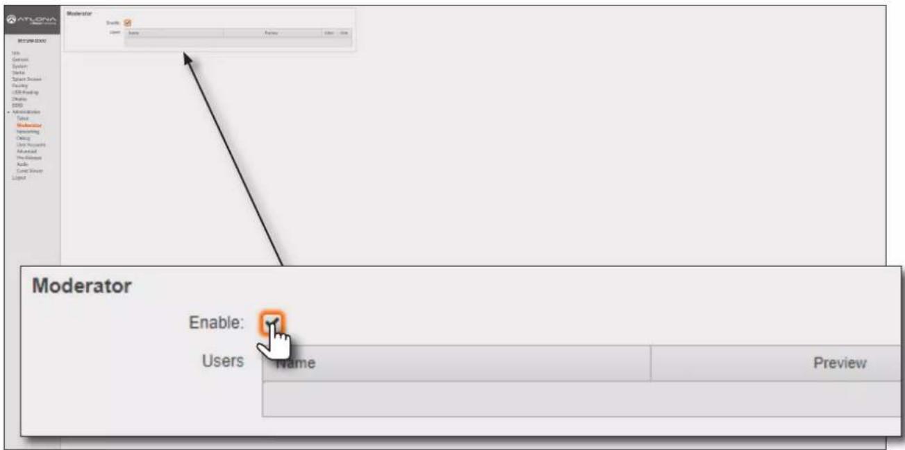
- Connect the BYOD devices to the AT-OME-MS52W. Once connected, the device can begin casting. Refer to Casting (page 56) for more information on how to connect devices for casting.
Once the devices have started casting, they will be displayed in the Users table, as shown in the example on the next page. Devices will only appear in this table when they are casting. When devices are displayed in this table, an Allow and Kick button will also be available for each device.
Device Operation
- Click the Allow button to permit a device to begin casting to the display device.
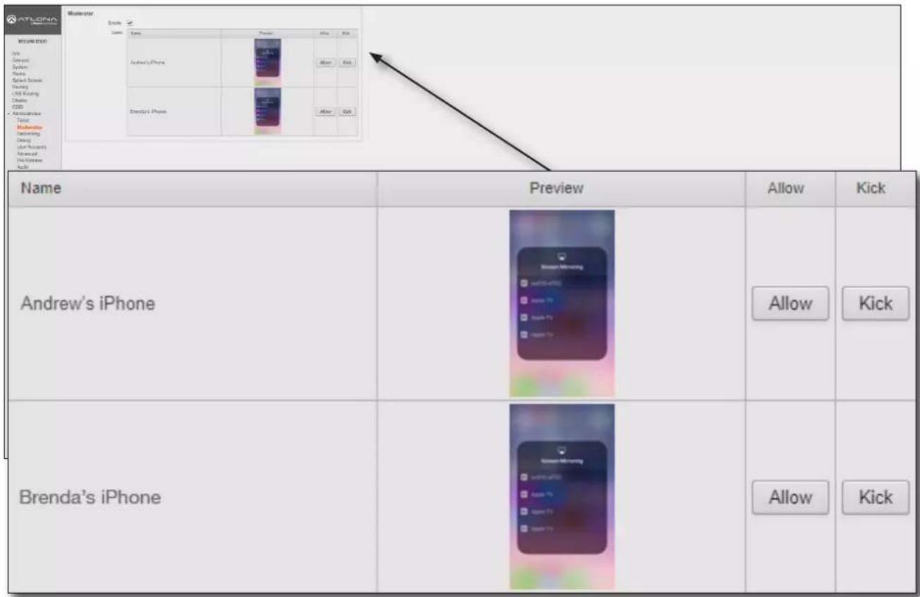
Once the selected device is allowed to cast to the connected display device, the Allow button will be disabled. In the example below, Brenda's iPhone is now the active casting device and shown on the display device.
- Click the Allow button, next to another device, to make that device the active casting device. Clicking the Allow button, allows switching between multiple casting devices that are connected to the AT-OME-MS52W. Note that it may take a few moments before the content from the casting device appears on the screen.
| Name | Preview | Allow | Kick |
| Andrew's iPhone | Active casting device | Allow | Kick |
| Brenda's iPhone | Allow | Kick |
Device Operation
- Click the Kick button to explicitly disconnect a casting device from the AT-OME-MS52W. Any casting device can be "kicked", even if it is the active casting device.
| Name | Preview | Allow | Kick |
| Andrew's iPhone | Allow | Kick | |
| Brenda's iPhone | Active casting device |
Once a device has been "kicked", it will no longer appear in the Users table. In the example below, the device Andrew's iPhone has been removed from the Users table.
- To reconnect a device that has been "kicked", select the hostname of the AT-OME-MS52W from the cast menu of the BYOD device. After a successful connection, the device will appear in the Users table.
| Name | Preview | Allow | Kick |
| Brenda's iPhone | Allow | Kick |
Display Control Methods
The AT-OME-MS52W provides various methods for display control. The following section describes and provides instructions for each method. By default, the AT-OME-MS52W uses CEC commands to control the display.
Active Video Presence
This method will instruct the AT-OME-MS52W to toggle power on the display, based on the absence/presence of either a video signal on any of the physical inputs or a casting device. The Auto Power Off Timer interval must expire before the display is turned off. AutoSwitch must also be enabled for this method to work.
- Login to the web server. Refer to Logging in to the Web Server (page 20) for more information.
- Click Display in the side menu bar.
- Under the Control window group, make sure that the AutoSwitch checkbox is checked. This feature must be enabled.
- Click the Display Control Method drop-down list and select Active Video Presence.
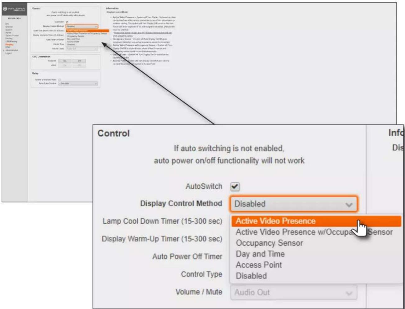
- Click the Auto Power Off Timer drop-down list and select the desired time interval. This is the amount of time that must elapse, before the display is turned off.
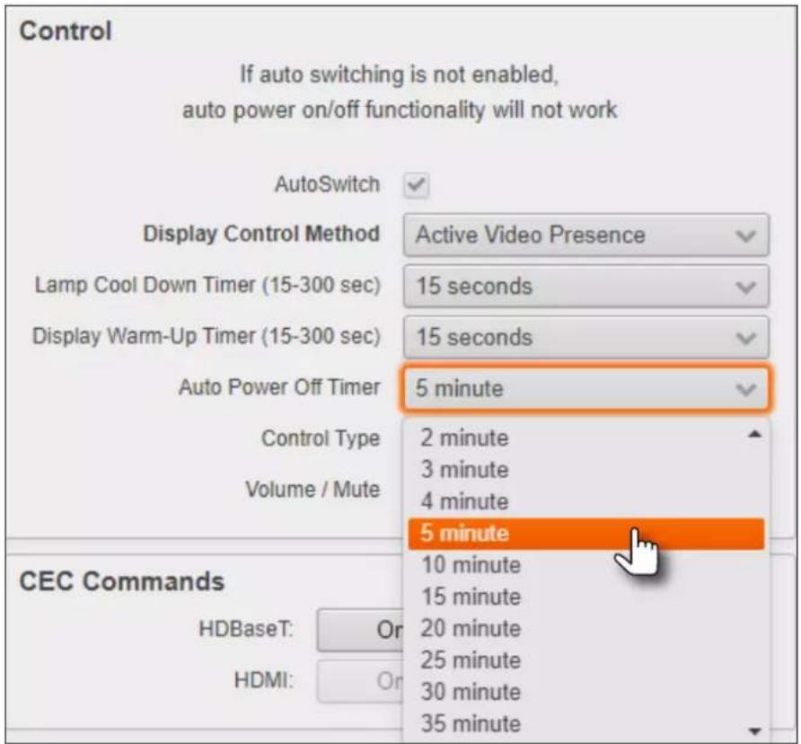
- Setup is complete.
Active Video Presence with Occupancy Sensor
This method is similar to the Active Video Presence mode, except that an occupancy sensor can also be used to provide hybrid operation. If using this mode, an occupancy sensor should be connected to the TRIGGER I/O port on the AT-OME-MS52W. Refer to Trigger I/O (page 11) for wiring information.
- Login to the web server. Refer to Logging in to the Web Server (page 20) for more information.
- Click Display in the side menu bar.
- Under the Control window group, make sure that the AutoSwitch checkbox is checked. This feature must be enabled.
- Click the Display Control Method drop-down list and select Active Video Presence w/Occupancy Sensor.
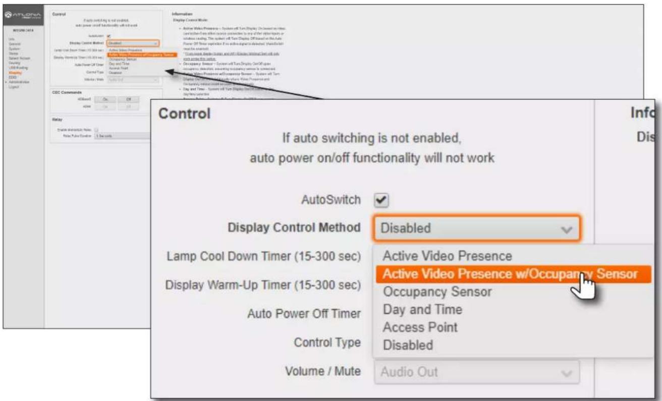
- The Trigger I/O window group will be displayed, along with two checkboxes: Enable Trigger On and Enable Trigger Off.
Check the Enable Trigger On checkbox to enable a power-on state when the trigger voltage is pulled from low to high. Check the Enable Trigger Off checkbox to enable a power-off state when the trigger voltage is pulled from low to high. Either or both checkboxes can be enabled. When enabled, all other display power options are overridden.
Occupancy Sensor Control
Turn Display On on Occupancy
Turn Display Off on Vacancy

- Setup is complete.
Occupancy Sensor
The following provides instructions on adding the AT-OCS-900N occupancy sensor as a device. The AutoSwitch feature on the AT-OME-MS52W does not need to be enabled for this to work.

IMPORTANT: A username and password must be configured on the AT-OCS-900N before using the device with the AT-OME-MS52W.
- Connect the AT-OCS-900N to the network. Refer to the AT-OCS-900N User Manual for more information.
- Login to the web server. Refer to Logging in to the Web Server (page 20) for more information.
- Click Display in the side menu bar.
- Click the Display Control Method drop-down list and select Occupancy Sensor.
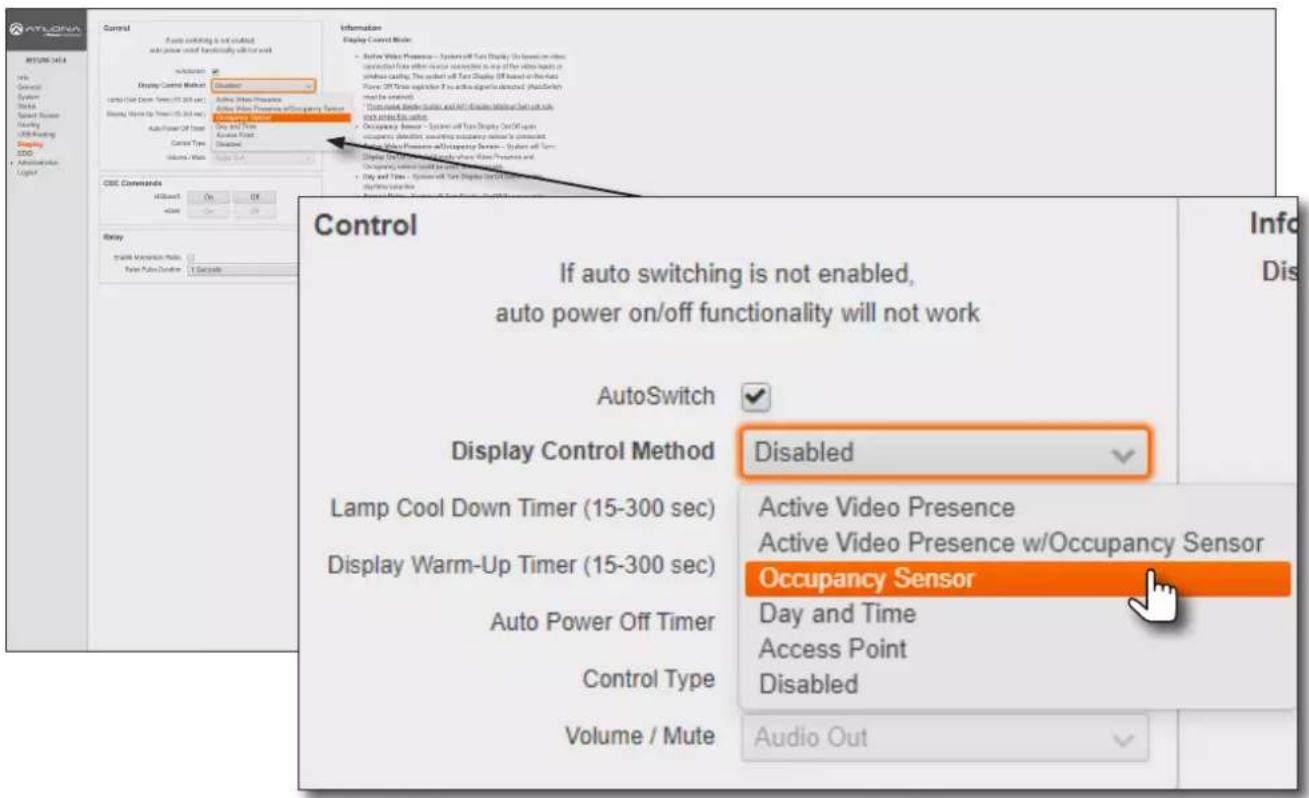
- The Occupancy Sensor Control window group will be displayed, as shown:
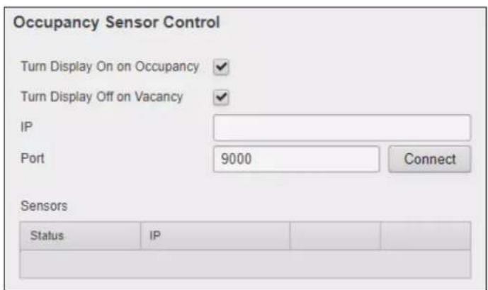
Device Operation
- Click the Turn Display On on Occupancy checkbox to enable or disable this feature. When enabled, a checkmark will appear in the checkbox and the occupancy sensor will power-on the display when the room is occupied.
- Click the Turn Display Off on Vacancy checkbox to enable or disable this feature. When enabled, a checkmark will appear in the checkbox and the occupancy sensor will power-off the display when the room is no longer occupied.
- Enter the IP address of the occupancy sensor in the IP field.
- Enter the port number in the Port field. The default port setting is 9000.

IMPORTANT: When adding an occupancy sensor, it is recommended that a static IP address is assigned to the occupancy sensor. DHCP is not recommended.
- Click the Connect button to connect to the occupancy sensor. All connected occupancy sensors will appear under the Sensors section, as shown below.
- Click the Identify button to identify the occupancy sensor. This feature is useful when multiple sensors are connected. See Example A below.

NOTE: The AT-OME-MS52W supports a maximum of three AT-OCS-900N devices.
- Click the Remove button to delete a sensor from the Sensors list.
- Setup is complete.
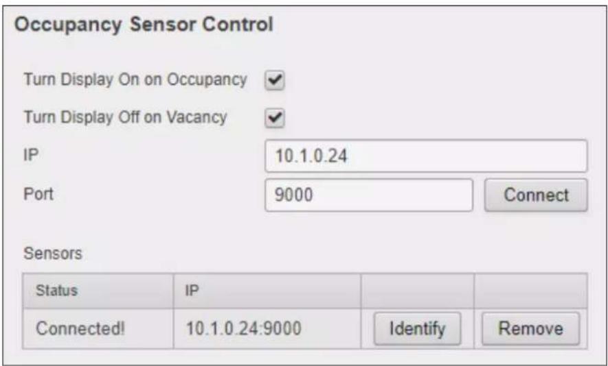
Example A - Multiple occupancy sensors added to the AT-OME-MS52W.
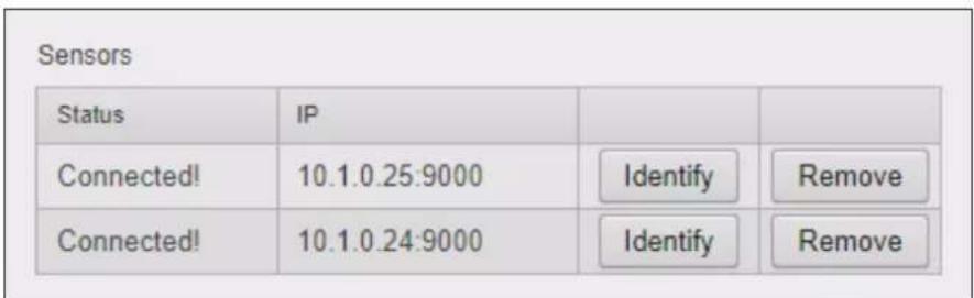
Day and Time
This method allows manual setup of day and time to determine when the display device will be power-on and powered-off. AutoSwitch does not need to be enabled for this feature to work.
- Login to the web server. Refer to Logging in to the Web Server (page 20) for more information.
- Click Display in the side menu bar.
- Click the Display Control Method drop-down list and select Day and Time.
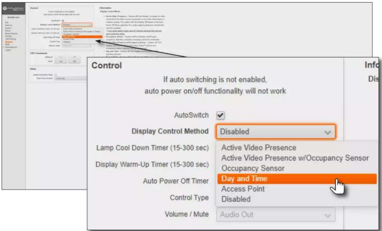
- The Time Display Control window group will be displayed.
- Click the Start Time drop-down lists to select the time when the display should be powered-on.
- Click the End Time drop-down lists to select the display power-off time.
- Click the Timezone drop-down list to select the correct time zone.
- Click the desired checkboxes to select which days to apply the schedule.
- Setup is complete.
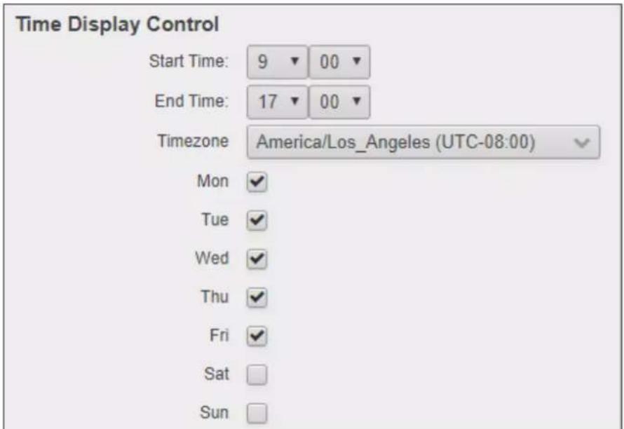
Device Operation
Access Point
This method uses the presence or a absence of a wireless connection to determine the power state of the system. In order for this feature to work, the AT-OME-MS52W must be set as an Access Point. Refer to Access Point Mode (page 45) for more information.
- Login to the web server. Refer to Logging in to the Web Server (page 20) for more information.
- Click Display in the side menu bar.
- Click the Display Control Method drop-down list and select Access Point.
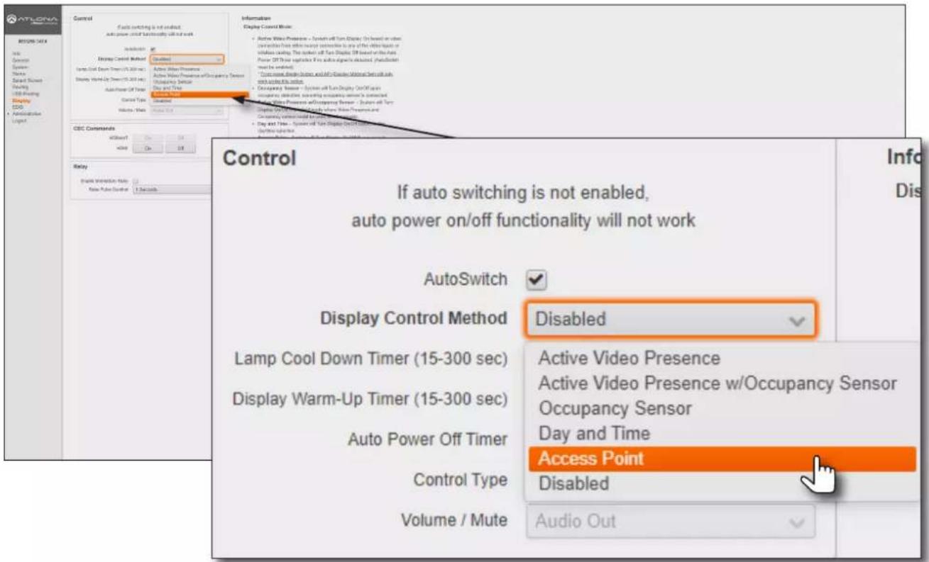
- Setup is complete.
Changing the Password
- Login to the web server. Refer to Logging in to the Web Server (page 20) for more information.
- Click Administration > User Accounts in the side menu bar.
- Under the User Accounts window group, click the Change button.
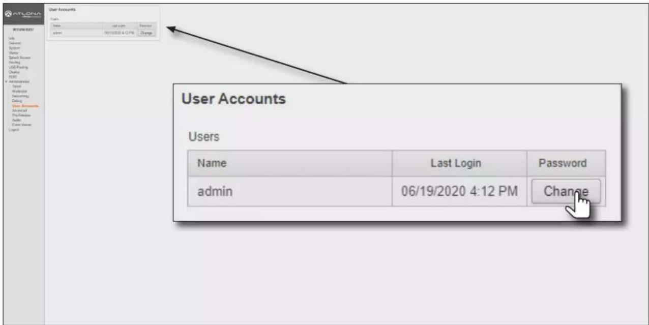
- The Change Password: admin dialog box will be displayed. Enter the new password in the Password field. Make sure to delete all the asterisks (masks) in this field before entering the new password.
- To confirm the password, enter the same password in the Repeat Password field. Make sure to delete all the asterisks (masks) in this field before entering the new password.
- Click the Save button to commit changes.
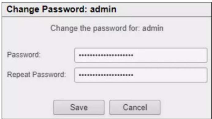
Configuration and Management Interfaces
Web Server
The AT-OME-MS52W includes a built-in web server. Atlona recommends that the web server be used to set up the AT-OME-MS52W, as it provides intuitive management of all features. Refer to Logging in to the Web Server (page 20) for more information.
Login Register page
This page is displayed when the AT-OME-MS52W web server is launched for the first time.
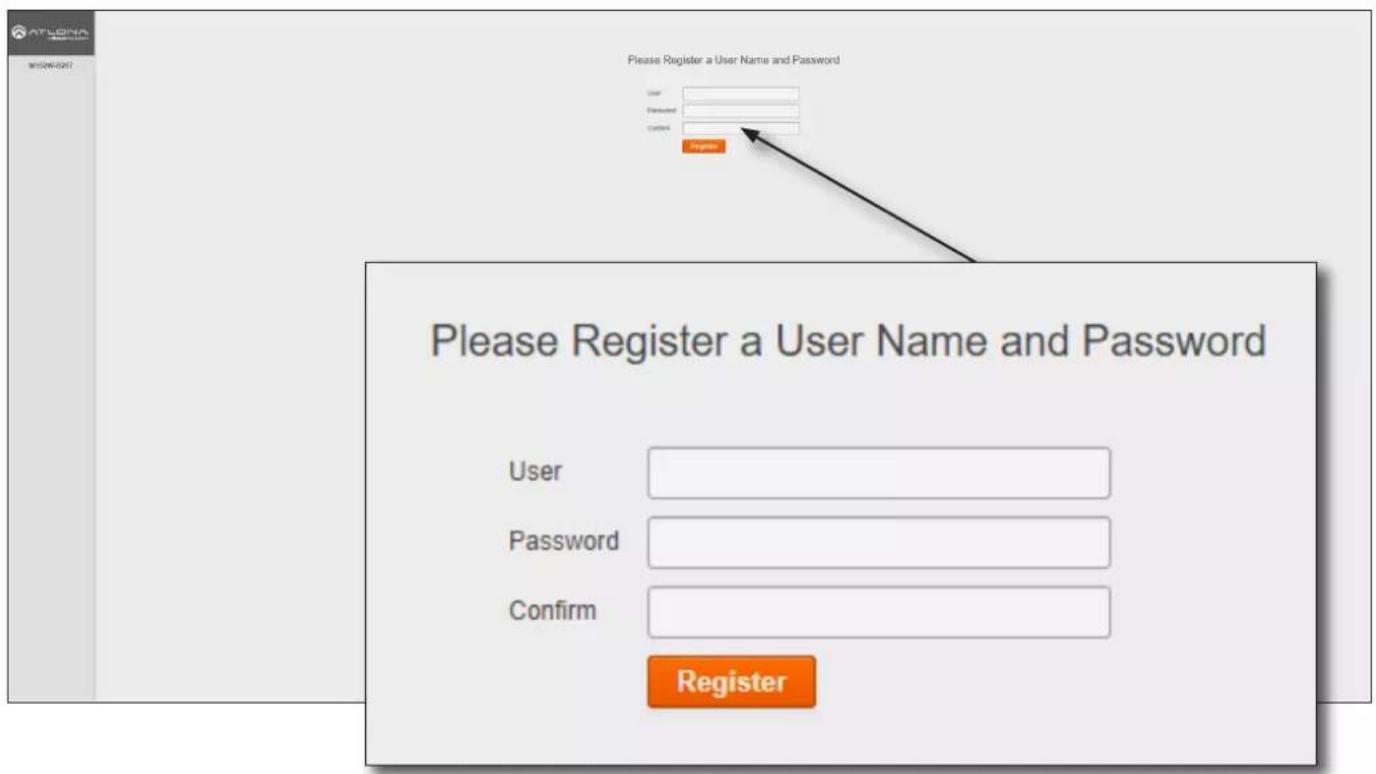
User
Enter the desired username in this field.
Password
Enter the desired password in this field.
Confirm
Re-enter the desired password in this field.
Register
Click this button to register the username and password with the AT-OME-MS52W.
Configuration and Management Interfaces
Login page
This page is displayed when the IP address of the AT-OME-MS52W is entered in the address bar of a web browser.
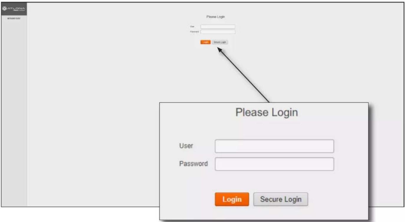
User
Enter the username in this field.
Password
Enter the password in this field.
Login
Click this button to login.
Secure Login
Click this button to login, if a secure connection is being used.
Configuration and Management Interfaces
Info page
After logging in, the Info page will be displayed. The Info page provides basic information about the receiver, including the model name, software version, input video timing, and the device being using as the transmitter.
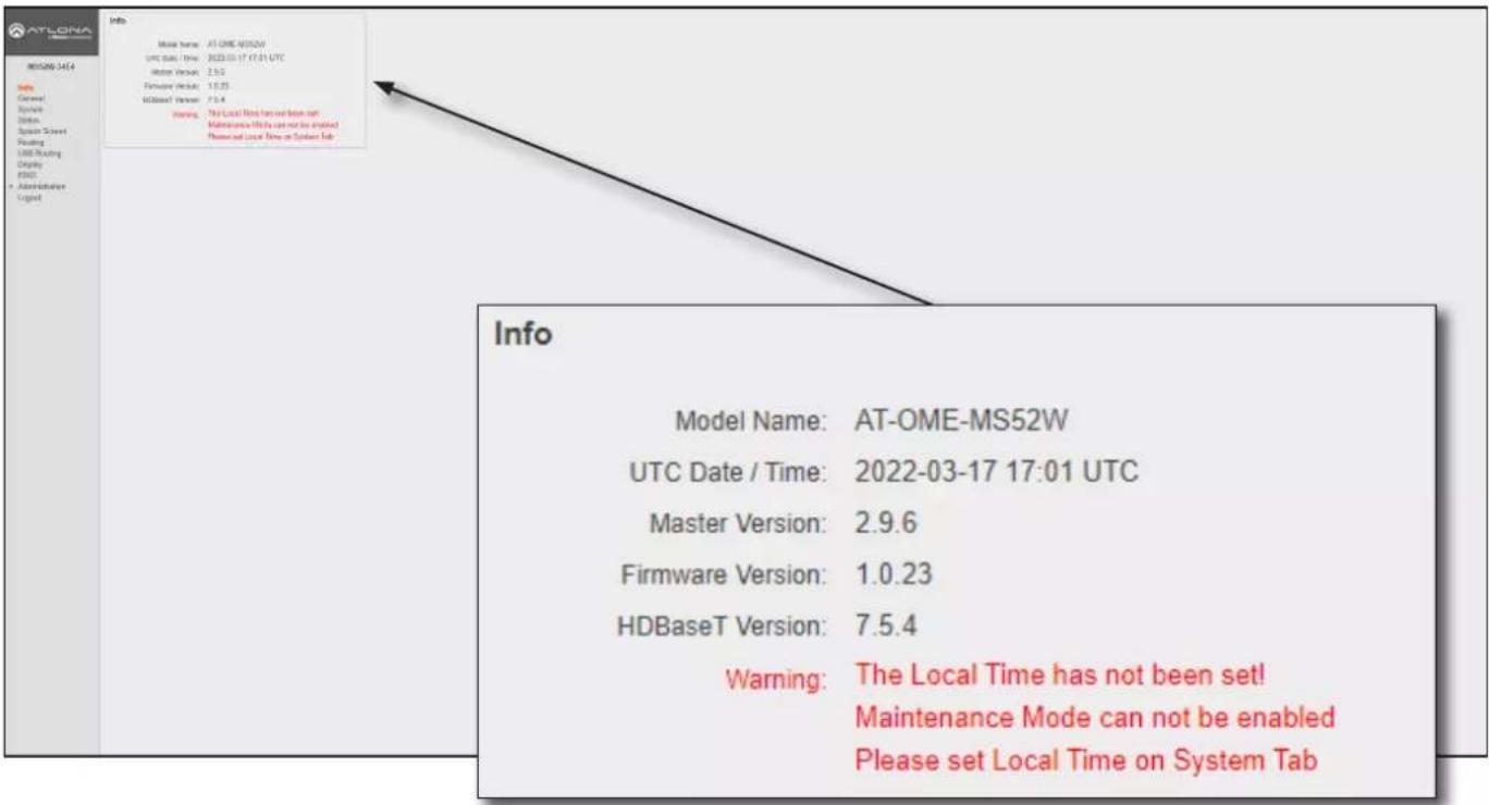
Info
Model Name
The model SKU of this product.
UTC Date / Time
The current time and date, in Universal Coordinated Time (UTC).
Master Version
The version of firmware.
Firmware Version
The version of firmware that the AT-OME-MS52W is running. Always make sure to check the AT-OME-MS52W product page, on the Atlona web site, for the latest version of firmware.
HDBaseT Version
The HDBaseT version of firmware that the AT-OME-MS52W is running.

NOTE: When the local time has not been set, the warning message (shown above) will be displayed in the Info window group. The local time must be set before maintenance mode can be enabled. Refer to Setting the System Date and Time (page 22) for more information on setting the local time.
Configuration and Management Interfaces
General page
General
Name
This is the hostname of the unit. Enter the desired name of the AT-OME-MS52W in this text field. Include the {id} tag to use the last four digits of the hardware MAC address. Hostnames can contain alphabetic and numeric characters.
NOTE: The hardware MAC address differs from the MAC address of the unit, which is found on an adhesive label applied to the bottom of the unit.
Display Name
The name based on the information provided in the Name field. This name is used by the AT-OME-MS52W to identify it within the OSD.
Derived
This field will automatically be populated by the AT-OME-MS52W, based on the information provided in the Name field. This field provides a “computer-friendly” name used by the SSID. If special characters and/or spaces are included in the Name field, then these are removed when populating this field.
Save
Click this button to accept all changes.
Revert
Click this button to abort changes and reset the previous text in the Name field.
Configuration and Management Interfaces
System page
![ATLONIA MS52W-34E4 System Display Name: MS52W-34E4 Restart: Restart Shutdown: Shutdown Factory Reset: Reset Time Display Name: MS52W-34E4 Restart: Restart Shutdown: Shutdown Factory Reset: Reset Time System Date / Time: Set Jul 5 2022, 19:15 [UTC] • System time must be set as UTC. Find the current time here. Local Date / Time: Set Jul 5 2022, 11:15 [-08:00] NTP Server: pool.ntp.org System OK General Systems Status System Status Reading Used Reading Display OSCC Administration Lighted Display Name: MS52W-34E4 Display Name: MS52W-34E4 Restart: Restart Shutdown: Shutdown Factory Reset: Reset Time System Date / Time: Set Jul 5 2022, 19:15 [UTC] • System time must be set as UTC. Find the current time here. Local Date / Time: Set Jul 5 2022, 11:15 [-08:00] NTP Server: pool.ntp.org](/content/2026/05/896898/images/c67c3138a0f09c4a59fd1eabbb26fa70cb4158b26b88af754d3cae9e943ee176.jpg)
Display name
This field serves as the SSID, when connecting wirelessly to the AT-OME-MS52W. This name can be changed in the Name field of the General tab. Refer to General page (page 80) for more information.
Restart
Click this button to reboot the AT-OME-MS52W.
Shutdown
Click this button to shut down the AT-OME-MS52W. This should always be performed before disconnecting power from the unit.
Factory Reset
Click the Reset button to reset the AT-OME-MS52W to factory-default settings. Resetting to factory-default setting may take up to five minutes to complete. Refer to Resetting to Factory-Default Settings (page 18) for the list of default settings.
Time
Set (System Date / Time)
Click this button to set the month, day, and time (in UTC).
Set (Local Date / Time)
Click this button to set the local date and time using the NTP server specified in the NTP Server field.
NTP Server
Enter the desired NTP server in this field.
Configuration and Management Interfaces
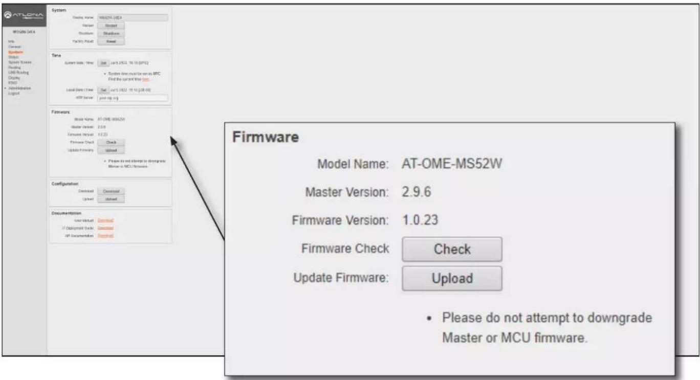
Firmware
Model Name
The SKU of the product: AT-OME-MS52W.
Master Version
The master version of firmware. Always make sure to check the AT-OME-MS52W product page, on the Atlona web site, for the latest version of firmware.
Download
Click this link to download the latest firmware. The most recent firmware version is listed.
Firmware Version
The version of (MCU) firmware that the AT-OME-MS52W is running. Always make sure to check the AT-OME-MS52W product page, on the Atlona web site, for the latest version of firmware.
Firmware Check
Click the Check button to check for the latest version of firmware. Each time the unit is rebooted, this feature is performed, automatically. The AT-OME-MS52W must be connected to the Internet to use this feature.
Update Firmware
Click the Upload button to upload the firmware file to the AT-OME-MS52W. Refer to Updating the Firmware (page 115) for more information.
Configuration and Management Interfaces
![ATLONA 34.4 WISQW-34.4 Info General System System Server Switch Server Routing USB Routing Claying Windows Administration Logist System Display Name: WISQW-34.4 Default: Default: Default: Default: Time System Data / Time: Sum: 16.5 (2021, 10:18 [SPC)] • System data must be set in UTC Find the current time Local Data / Time: Sum: 16.5 (2021, 10:18 [SPC]) ASP Server: not up log Firmware: Model Name: AT-ONE/WISQW Master Services: 2.0.0 Framework Input: 10.23 Framework Check: Check Update Primary: Update • Please do not attempt to undergo Mouse or MCJ Network Configuration: Download: Download Upload: Update Documentation: User Manual: download If Deployment Guide: download UP Documentation: download Configuration Download: Download Upload: Upload Documentation User Manual: Download IT Deployment Guide: Download API Documentation: Download](/content/2026/05/896898/images/f5fe783b1fcfa51bad42959ced596afcc0e75e41e66d7ea2116dab4ab2d7ba6d.jpg)
Configuration
Download
Click this button to download the current AT-OME-MS52W configuration to a .zip file. The default filename is config.zip. Within the config.zip is the configuration.zip file. Note that the information within the configuration.zip file cannot be extracted as it is only readable by the AT-OME-MS52W.
Upload
Click this button to upload the configuration file to the AT-OME-MS52W. Both the Download and Upload button are useful to save and load different configurations and/or to provide a backup, in the unlikely event of a system failure.
Documentation
User Manual
Click the Download link to view the latest version of the User Manual.
IT Deployment Guide
Click the Download link to view the IT Deployment Guide.
API Documentation
Click the Download link to view the latest API documentation.
Configuration and Management Interfaces
Status page
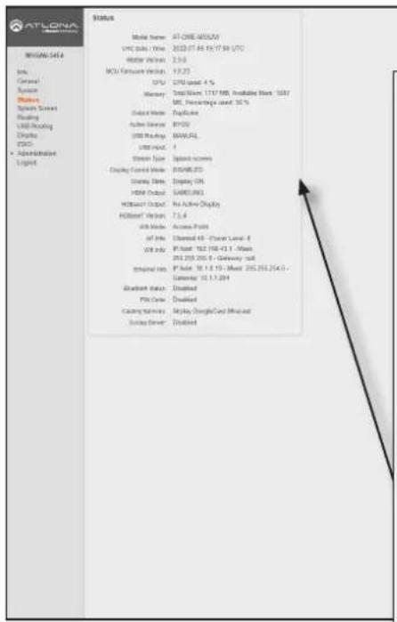
Status
Model Name: AT-OME-MS52W
UTC Date / Time: 2022-07-05 19:17:58 UTC
Master Version: 2.9.6
MCU Firmware Version: 1.0.23
CPU: CPU used: 4 %
Memory: Total Mem: 1717 MB, Available Mem: 1087
MB, Percentage used: 36 %
Output Mode: Duplicate
Active Source: BYOD
USB Routing: MANUAL
USB Input: 1
Stream Type: Splash screen
Display Control Mode: DISABLED
Display State: Display ON
HDMI Output: SAMSUNG
HDBaseT Output: No Active Display
HDBaseT Version: 7.5.4
Wifi Mode: Access Point
AP Info: Channel 48 - Power Level: 0
Wifi Info: IP Addr: 192.168.43.1 - Mask:
255.255.255.0 - Gateway: null
Ethernet Info IP Addr: 10.1.0.19 - Mask: 255.255.254.0 -
Gateway: 10.1.1.254
Bluetooth status: Disabled
PIN Code: Disabled
Casting Services: Airplay GoogleCast Miracast
Syslog Server: Disabled
Status
This page provides a information about the current state of the AT-OME-MS52W, such as IP information, memory usage, casting devices, active sources, date/time, and various other settings.
Configuration and Management Interfaces
Splash Screen page
This page provides control over the appearance of the splash screen. Refer to The Splash Screen (page 34) for more information on using each of the settings under the Splash Screen and Images window groups.
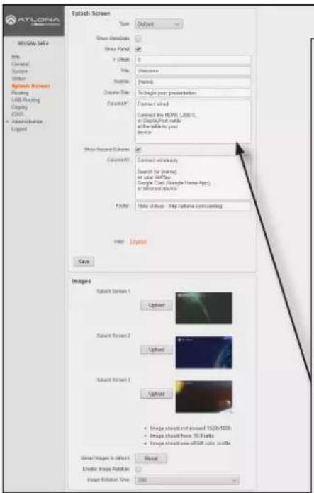
Splash Screen
Type
Click this drop-down list to select the type of splash screen to use.
Show Meta Data
Click this check box to display metadata on the splash screen.
Show Panel
Check this box to display the panel, containing connection instructions and other information.
Y Offset
Sets the up-and-down position of the overlay panel, on the screen. A value of 0 vertically positions the panel in the center of the screen. Positive values move the panel down. Negative values move the panel up.
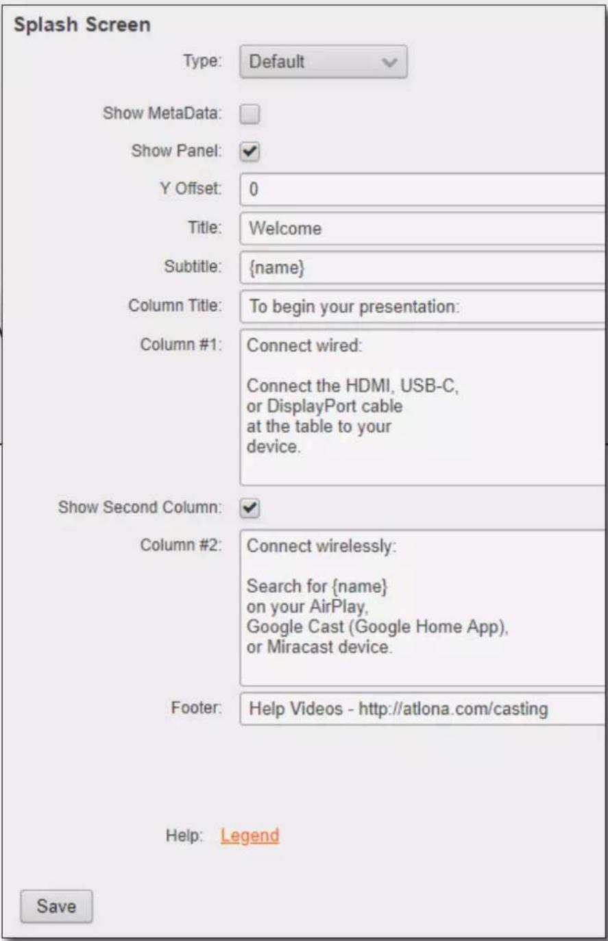
Title
The title of the overlay panel. The default value is "Welcome".
Subtitle
The text directly under the text in the Title field. The default text contains the name of the unit.
Configuration and Management Interfaces
Column Title
The title text for the centered text, above both instruction columns.
The default text is "To begin your presentation".
Column #1
The text positioned in the left column. The default text is "Connect wired: Connect the HDMI, USB-C, or DisplayPort cable at the table to your device".
Show Second Column
Check this box to display the second (right-hand) column. Uncheck this box to hide the text in this column.
Column #2
The text positioned in the right-hand column. The default text is "Connect wirelessly: Connect the Wi-Fi network", entercode, and enable AirPlay, Google Cast™, or Miracast".
Footer
By default, this field provides a link to how casting works on different operating systems (www.atlona.com/casting). This field can be modified to contain a different URL, if desired. This link will be displayed on the default splash screen.
Legend
Click this link to display a list of available tags that can be used in any of the text fields. Refer to the illustration above.
Save
Click this button to commit all changes on this page.
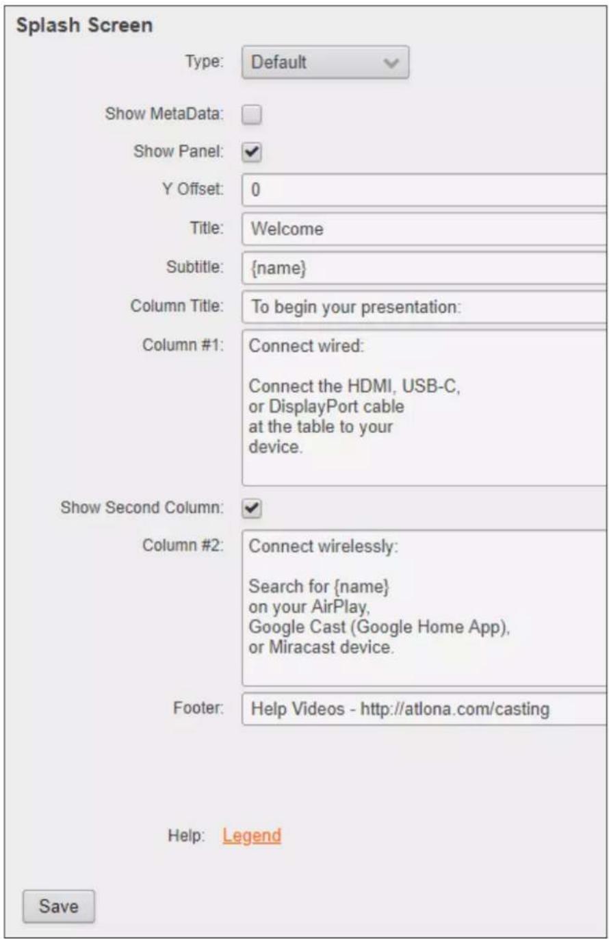
Configuration and Management Interfaces
![XPLASH Screen Type: Default Show window: Show Panel: 1 GHz: 2 View: Viewers: Viewers: Column Title: Column P: Connect audio: Connect the HDMI, USB-C, or DisplayPort color of the table to your device. Show Second Column: Selected: Connect exclusively: Search for [name] on play iPhone Google Cast (Google Frame App), or Microsoft Excel. Public: Help display. My details corresponding. Host: Login Images Show Screen 1 Imported Show Screen 2 Imported Show Screen 3 Imported Image should not cover (F23=0.005) Image should have 10% data Image should use all other color profiles Show Image to default Replace image to double Image Forward Time Add](/content/2026/05/896898/images/67bf1800087316f9abfe4f0b591225129ff2dcf58b2b50f0b31cfccf4ba87c1a.jpg)
Images
Upload
Click these buttons to replace each factory-default image with a custom image.
Reset Splash Images
Click the Reset button to set the splash screen images to the factory-default images.
Enable Image Rotation
Click this check box to instruct the AT-OME-MS52W to cycle through the splash screen images.
Images
Splash Screen 1
Upload

natural_image
Dark abstract image with faint curved light streaks, no visible text or symbolsSplash Screen 2
Upload

natural_image
Close-up of Earth from space with visible continents and cloud cover (no text or symbols)Splash Screen 3
Upload

natural_image
Close-up of a dark, textured surface with a bright circular spot in the foreground (no visible text or symbols)• Image should not exceed 1920x1080.
• Image should have 16:9 ratio.
• Image should use sRGB color profile.
Reset Images to default:
Reset
Enable Image Rotation:

Image Rotation Time:
300
Image Rotation Time
Click this drop-down list to select the image rotation interval.
Configuration and Management Interfaces
Routing page
This page provides control over the appearance of the splash screen. Refer to The Splash Screen (page 34) for more information on using each of the settings under the Splash Screen and Images window groups.
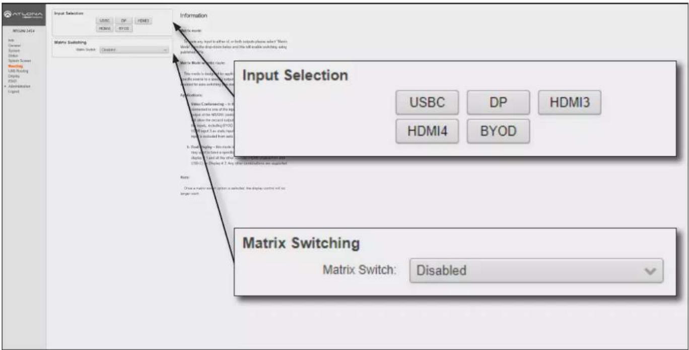
Input Selection
USBC, DP, HDMI3, HDMI4, BYOD
Click the desired button to select the active input.
Matrix Switching
Matrix Switch
Click this drop-down list to select the desired matrix mode. Refer to Switching Modes (page 25) for more information.
| Modes Description | |
| Disabled Matrix mode is disabled (default setting). | |
| Matrix Mode Allows the AT-OME-MS52W to independently switch between any input and any output. | |
| Matrix Mode w/ Static Route Use this mode when integrating the AT-OME-MS52W with a video conference system. | |
Fallback to Static Source
This checkbox will only be available when the Matrix Switch drop-down is set to Matrix Mode w/ static route. This option is used to set the fallback input. Normally, the input would fallback to BYOD if no source was present. However, checking this box will allow the input to fallback to the source specified in the Matrix Mode Static Source drop-down list.
Configuration and Management Interfaces
USB Routing page
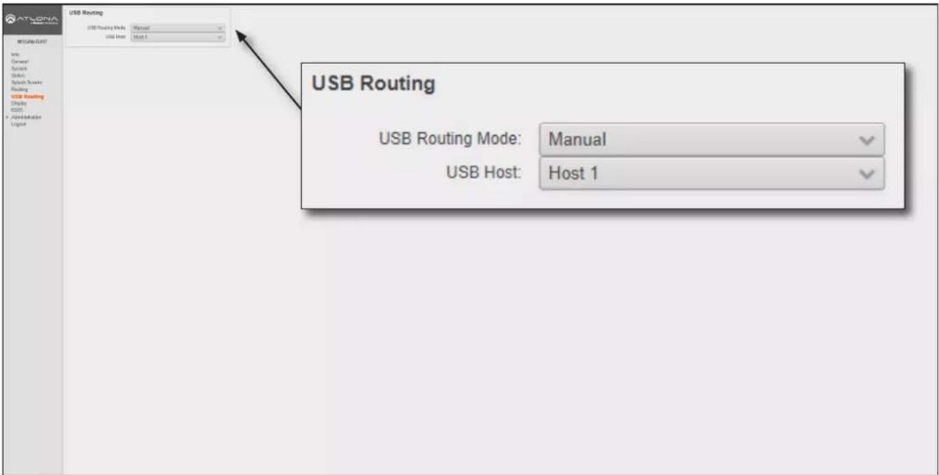
USB Routing
Refer to USB Modes (page 30) for more information.
USB Routing Mode
Click this drop-down list to select the USB routing mode.
| Modes Description | |
| Manual This is the default mode | and provides manual selection of the USB host port to be used, when switching video inputs. |
| Follow USB In this mode, the AT | AT-OME-MS52W will detect which USB ports are connected to a host device. If all USB host ports are connected to host devices, then the AT-OME-MS52W will set the last-connected USB host device as the “active” USB host. Use the procedure below to enable Follow USB mode. |
| Follow Video | In this mode, a video input can be paired with USB 1, USB 2, or a remote USB host port on a receiver. When a video input switch event occurs, the assigned USB host port will follow. Note in this mode that the USB-C port is not considered a host (data) port. |
Configuration and Management Interfaces
Display page
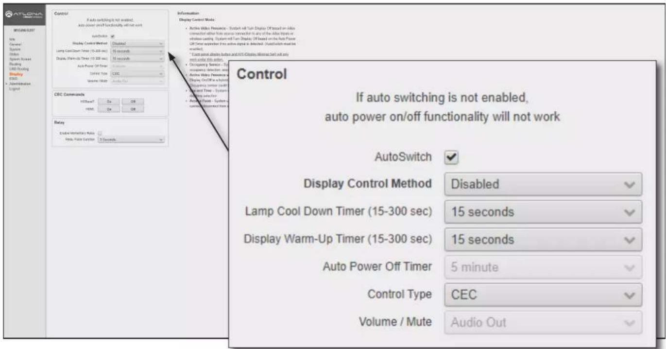
Control
AutoSwitch
Click this box to enable or disable auto-switching. When this box is checked, the AT-OME-MS52W will automatically switch inputs when the new device is connected. To disable auto-switching, uncheck this box.
Display Control Method
Click this drop-down list to select the method of display control. The following options are available.
| Modes Description | |
| Active Video Presence* The AT- | OME-MS52W will power-off the display if no active source is detected on the input. Conversely, the display will power-on when an active source is detected. This applies to either physical source connections or casting. The Auto Power Off Timer must expire before the power-off command is sent. |
| Active Video Presence w/Occupancy Sensor* | Similar to the Active Video Presence mode, except that an occupancy sensor can also be used with Active Video Presence mode to determine when the power-off or power-on command is sent. |
| Occupancy Sensor The AT-OME | E-MS52W will power-on/power-off the display based on the state of the occupancy sensor. The occupancy sensor must be wired to the AT-OME-MS52W. |
| Day and Time The AT-OME-MS | 52W will power-on/power-off the display based on the assigned schedule. |
| Access Point Display will power | -on/power-off based on the presence of a connection/disconnection from the AT-OME-MS52W Access Point. |
| Disabled No display control |
*AutoSwitch must be enabled to use these control methods.
Configuration and Management Interfaces
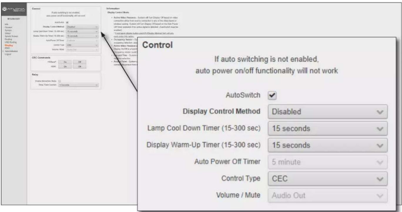
Lamp cool down timer
Sets the projector lamp cool-down timer, in seconds. This value specifies the time interval that must elapse, after the display control "off" command is sent, before the display "power on" command can be sent. This feature is used to prevent the projector from missing a "power on" command while the lamps are cooling. A minimum of 45 seconds is recommended for projectors. Available values are from 15 to 300 seconds (5 minutes). The default setting is 15 seconds.
Display Warm-Up Timer
Sets the projector lamp warm-up timer, in seconds. During the warm-up interval, the AT-OME-MS52W will not start the auto power-off timer. This value specifies the time interval that must elapse, after the display control “on” command is sent, before the display “power off” command can be sent. This feature is used to prevent a “power off” command from being sent while the lamps are warming up. A minimum of 45 seconds is recommended for projectors. Available values are 15 to 300 seconds (5 minutes). The default value is 15 seconds.
Auto power off timer
Sets the time interval before the command to power-off the display is sent, when an A/V signal is no longer present. The default value is 5 minutes. Available values are 15 seconds to 8 hours.
Control Type
Sets the control protocol for the connected display. Click this drop-down to select the control type. Available settings are CEC, IP, and RS-232. By default, CEC is selected for control of the display. IP and RS-232 can also be selected. When IP or RS-232 are selected, more fields are available.
Volume / Mute
This option is only available when Control Type is set to RS-232 or IP.
Configuration and Management Interfaces
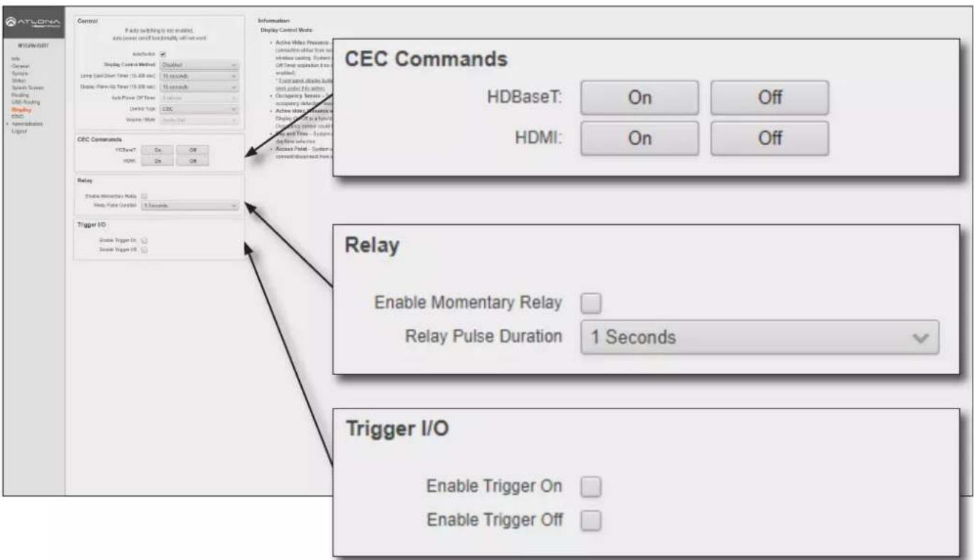
CEC Commands
Click these button to test CEC functionality over HDMI and HDBaseT. Click the On button to send the power-on command to the display device. Click the Off button to send the power-off command to the display device.
Relay
Enable Momentary Relay
When enabled, the relay is set to momentary. The default setting is disabled (latch). Use a 48 V DC relay with no more than 1 A current draw. This feature is disabled, by default. Refer to Relay (page 11) for wiring information.
Relay Pulse Duration
Click this drop-down list to select the desired pulse duration for the relay. Some devices may require different time intervals, to recognize a state change. Range: 1 to 10 seconds.
Trigger I/O
This section defines how the TRIGGER port will respond to varying voltage levels when, for example, used with an occupancy sensor. Either or both of the following conditions can be enabled or disabled. This section is only available when the Display Control Method is set to either Occupancy Sensor or Active Video Presence w/ Occupancy Sensor.
Enable Trigger On
Check this box to power-on the system when the occupancy sensor detects a presence in the room. If the Enable Trigger Off is not checked (enabled), hen the system power will remain on when the room is unoccupied.
Enable Trigger Off
Check this box to power-off the system when the occupancy sensor detects no presence in the room.
Configuration and Management Interfaces
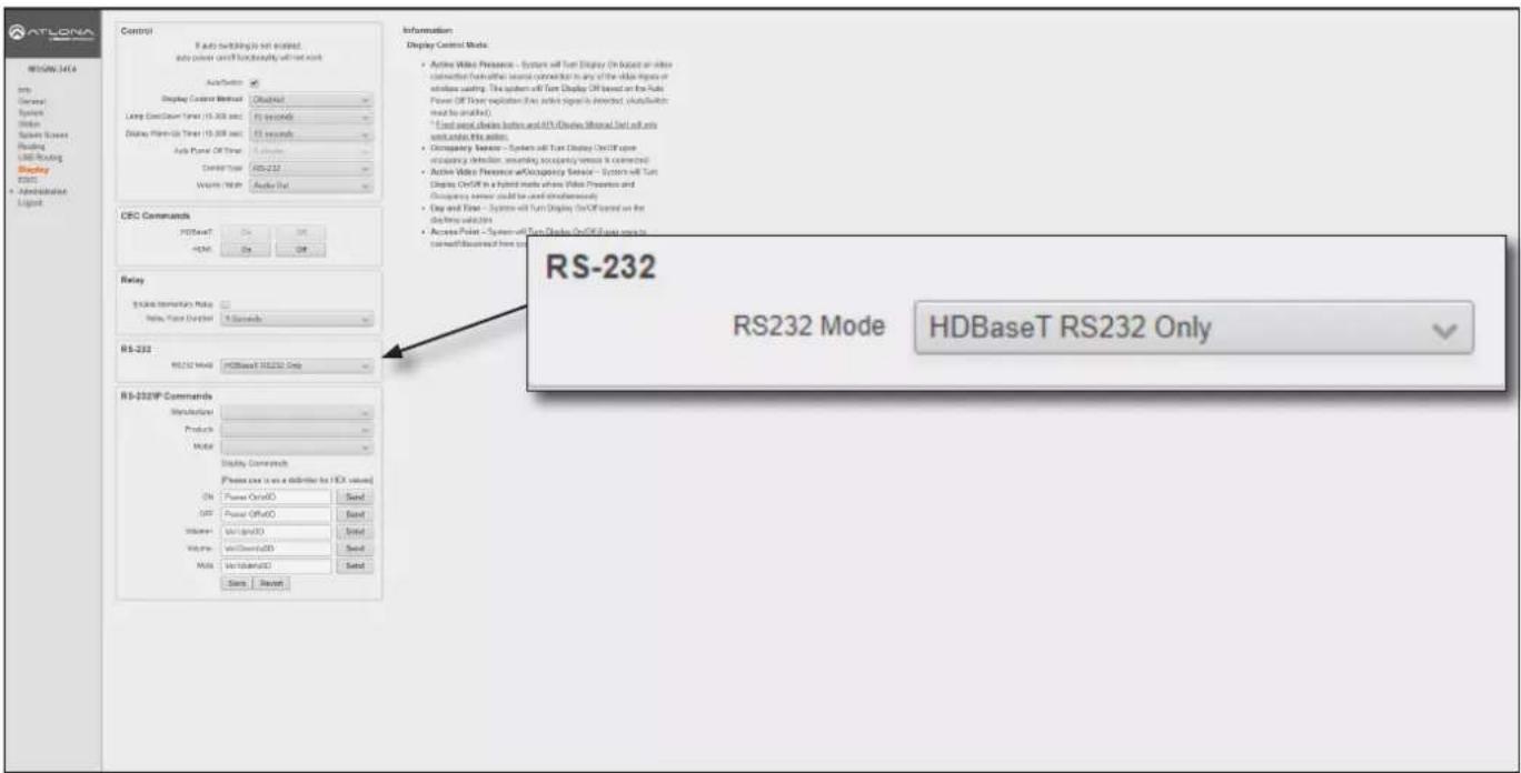
RS-232
This section is only available when the Control Type is set to RS-232. If RS-232 settings (baud rate, etc) need to be adjusted, refer to the RS232 Settings section under the Administration > Advanced page (page 107).
RS-232 Mode
Click this drop-down list to select the RS-232 mode.
| Setting Description | |
| HDBaseT RS232 Only | Assigns settings for RS-232 settings over HDBaseT OUT. RS-232 commands will only be transmitted over the HDBaseT OUT port. |
| Local RS232 Only | Assigns settings for RS-232 port for controlling the display over the local RS-232 port. |
| Both | Both HDBaseT OUT and the RS-232 port are used. RS-232 settings can be set independently for each port. |
Configuration and Management Interfaces
![ATLONA MEAN/047 Info General System Display Switch Routing USB Reading Display 0000 • Administration Logo Control If Auto switching is not enabled, Auto power card functionality will be used. AutoSwitch Display Control Method (Chamber) Long Cold Clean Time (10.00 sec) Display Power On Time (10.00 sec) Any Power Off Time (10.00 sec) Control Type (IP) Write Now (Audio Out) CRC Commands HOSV67 ON ON ON Relay Static Monetary Mode None, Frame Duration 5 Seconds IP IP 489X6 10.20 36.58 Port (R-66535) 23 RS-232/IP Commands Manufacturer PRODUCTS MODEL Display Commands (Please use it as a delimiter for HEX values) ON Power On/OOD Send UP Power UP/OOD Send ModelPT ModelPT/OOD Send WALM Vol Comte/OOD Send WALM Vol Material/OOD Send IP This section is only available when the Control Type is set to IP. IP address Enter the IP address of the display device in this field. Port Enter the port number in this field. Information: Display Control Mode: • Active Water Pressense - System will Turn Display Off based on other connection offset from internal connection to any of the other input or output loading. System will Turn Display Off based on the Auto Power Off Timer implementation if the active signal is deflated. (AudioSwitch must be enabled) • Enable print display before and ATS-Delta Materal Set will only exit under the author. • Occupancy Manager - System will Turn Display Ctrl/Ope. Occupancy Manager running occupancy server is estimated. • Active Water Pressense Display On/OFF is a hybrid Occupancy Member set all Day and Time - System Day and Time - System Day time solution • Access Port - System control/Accessed from port IP IP address 10.20.50.58 Port [0-65535] 23 RS-232/IP Commands Manufacturer Products Model Display Commands [Please use \x as a delimiter for HEX values] ON Power On\x0D Send OFF Power Off\x0D Send Volume+ Vol Up\x0D Send Volume- Vol Down\x0D Send Mute Vol Mute\x0D Send Save Revert IP This section is only available when the Control Type is set to IP. IP address Enter the IP address of the display device in this field. Port Enter the port number in this field.](/content/2026/05/896898/images/fc775b4229c775b758ee5f3744b1fcaed47c8f5ee5a63288c390684f7e13449f.jpg)
RS-232/IP Commands
This section is only available when the Control Type is set to either RS-232 or IP.
Manufacturer
Click this drop-down list to select the display manufacturer. If the display device being controlled is not in this list, then the commands can be entered manually.
| Acer Hitachi Qomo | ||
| Barco Infocus Samsung | ||
| Benq JVC Sharp | ||
| Canon LG Smart | ||
| Casio NEC Sony | ||
| Christie Optima Toshiba | ||
| Clevertouch Panasonic ViewSonic | ||
| Digital Projection Philips Vivitek | ||
| Eiki | Pjlink | |
| Epson | Planar | |
Configuration and Management Interfaces
![RS-232/IP Commands Manufacturer Products Model Display Commands [Please use \x as a delimiter for HEX values] ON Power On\x0D Send OFF Power Off\x0D Send Volume+ Vol Up\x0D Send Volume- Vol Down\x0D Send Mute Vol Mute\x0D Send Save Revert](/content/2026/05/896898/images/316b0c223d0daa571748a04869067c4d011a7c4098f77495cb354b64428f3c46.jpg)
Products
Click this drop-down list to select the product. This drop-down list will be populated, based on the selection made from the Manufacturer drop-down list.
Model
Click this drop-down list to select the model. This drop-down list will be populated based on the selection made in the Products drop-down list.
Display Commands
Once a device is selected, the ON, OFF, Volume+, Volume-, and Mute fields will be populated with the correct information for that device. If a device is not listed, enter the appropriate commands the device in each field. Commands can be either ASCII or hexadecimal. If hexadecimal values are used, then use the /x delimiter at the end of the string. Click the Send button to verify that each command works properly. If not, check the values entered for each command.
Save
Click this button to commit all changes.
Revert
Click this button to undo all changes.
Configuration and Management Interfaces
EDID page
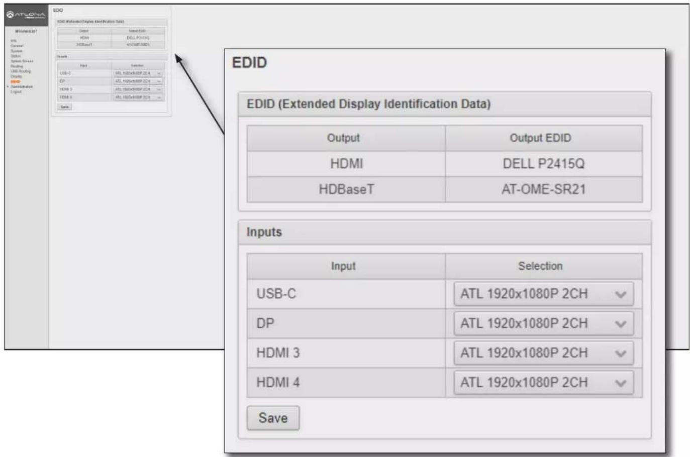
EDID
EDID (Extended Display Identification Data)
Displays the EDID assigned that is being used by each output. Press the Save button to save the EDID to a file.
Inputs
The Input column displays each of the inputs on the AT-OME-MS52W. Click the drop-down list, under the Selection column, to select the desired EDID to be used. The table below lists the available EDID presets.
The table below provides a listing of available EDID presets.
| EDID listing | |
| 4K60 2CH 1366x768@60 2CH | |
| 4K30 2CH 1280x800p60 2CH | |
| 4K30 4:4:4 2CH 1280x720p60 2CH | |
| 1920x1200p60 2CH 1024x768p60 2CH | |
| 1920x1080P 2CH (factory-default) 800x600p60 2CH | |
| 1600x900p@60 2CH |
Save
Click this button to commit changes.
Configuration and Management Interfaces
Administration > Telnet page
The Telnet page provides an emulated terminal for entering commands.
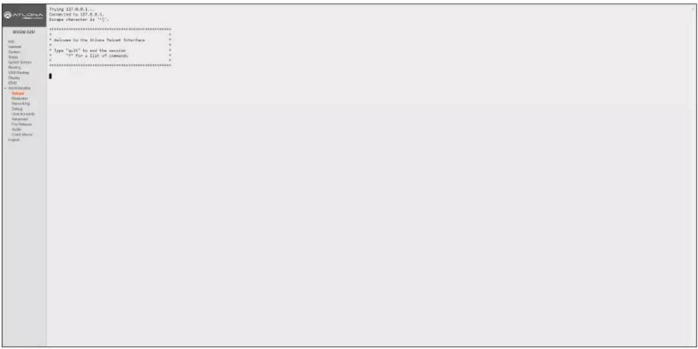
Configuration and Management Interfaces
Administration > Moderator page
The Moderator page provides control of which device, that are casting, are permitted to display content. Refer to Moderator Mode (page 66) for more information.
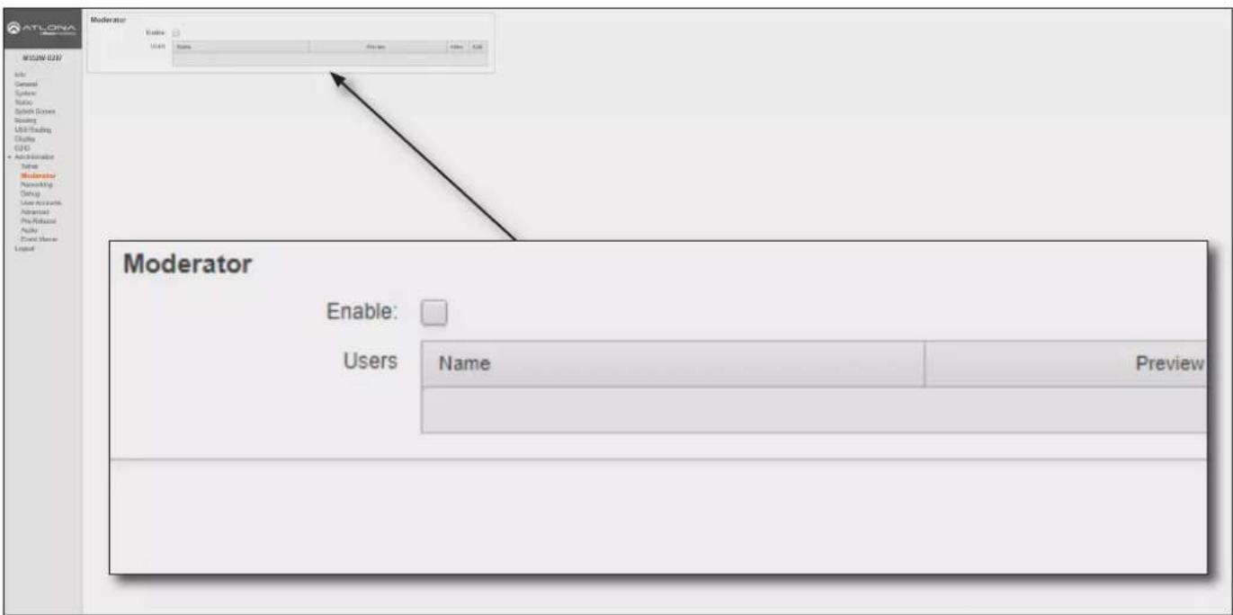
Moderator
Enable
Click this check box to enable or disable Moderator mode. If this box is checked, then Moderator mode is enabled. In order to monitor which devices are allowed to display content, this box must be checked before a device begins casting. If a device is already casting, then enabling this feature will have no effect.
Users
This table lists all users which are casting using the AT-OME-MS52W. Up to four users can be hosted at one time, but only one can be displayed at a time. Devices will only appear in this table when they are casting. Moderator mode must be enabled for devices to be displayed in this table. When casting devices are displays an Allow and Kick button will also be displayed.
Configuration and Management Interfaces
Administration > Networking page
This page contains a WiFi and Ethernet tab. Use the settings, under these tabs, to connect the AT-OME-MS52W to a network or wireless Access Point (AP). Refer to the IT Network Deployment Guide for detailed information on configuring the AT-OME-MS52W in various network environments.
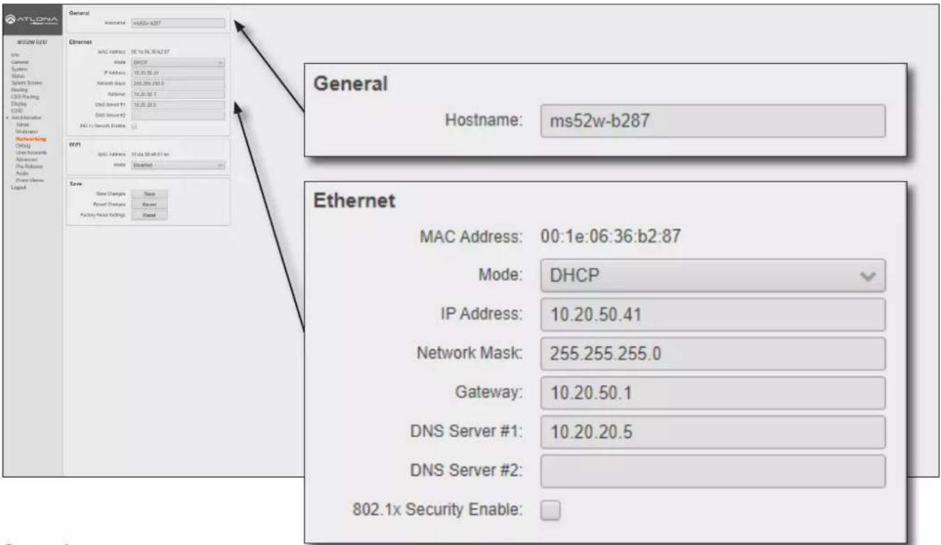
General
Hostname
The name assigned to the AT-OME-MS52W. This name can be changed, if desired. Refer to Changing the SSID (page 52) for more information.
Ethernet
MAC Address
Displays the MAC address of the AT-OME-MS52W.
Mode
Click this drop-down list to select the desired IP mode.
| Setting Description | |
| DHCP Select this option to have a DHCP server (if available) assign an IP address to the AT-OME-MS52W. | |
| Static | Select this option to enter a specific IP address. When set to Static mode, the subnet mask, gateway, and DNS servers can be specified. |
| Factory Static | Select this option to use the factory-default wired network settings. In this mode, only the DNS Server fields can be modified. The IP Address, Network Mask, and Gateway fields will be set to the following values:IP Address = 192.168.1.254Network Mask = 255.255.0.0Gateway = 192.168.1.1 |
Configuration and Management Interfaces
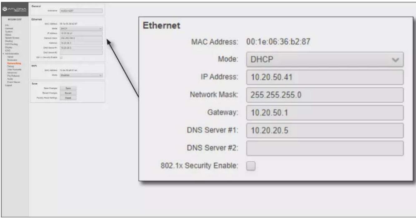
IP Address
Enter the desired IP address for the AT-OME-MS52W in this field. This field can only be changed when Mode is set to Static.
Network Mask
Enter the subnet mask in this field. This field can only be changed when Mode is set to Static.
Gateway
Enter the gateway (router) address in this field. This field can only be changed when Mode is set to Static.
DNS Server #1 / DNS Server #2
Enter the DNS server addresses in the DNS Server #1 and DNS Server #2 fields. If the AT-OME-MS52W will be used within an internal LAN, this information is not required. This field can only be changed when Mode is set to Static.
802.1x Security Enable
Click this checkbox to enable 802.1x authentication mode. When enabled, the RADIUS server, RADIUS port, and RADIUS secret fields will be available. Refer to 802.1X Authentication (page 53) for more information.
Configuration and Management Interfaces
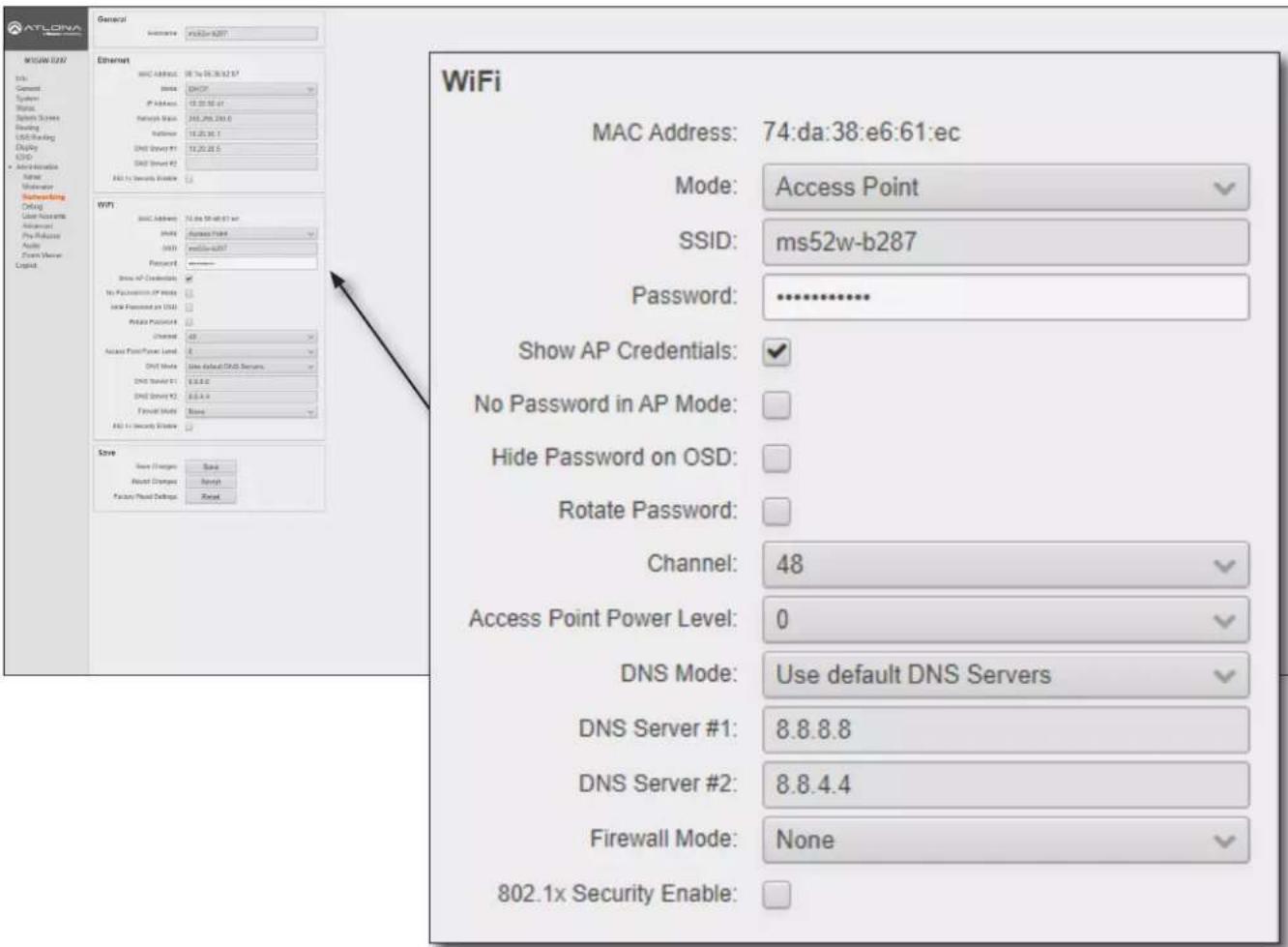
WiFi - Access Point Mode
Mode
Click this drop-down list to select the desired WiFi mode.
| Setting Description | |
| Access Point Select this option | to configure the AT-OME-MS52W as a Wireless Access Point,allowing other wireless devices to connect to the same wired network as the AT-OME-MS52W. |
| Connect to WiFi Select this mode | to connect the AT-OME-MS52W to the specified SSID of a wireless host. |
| Disabled Select this mode to disable Wi-Fi on the AT-OME-MS52W. | |
SSID
The SSID assigned to the AT-OME-MS52W. The SSID name can be changed. Refer to Changing the SSID (page 52) for more information.
Password
Enter the password required to connect to the AT-OME-MS52W.
Show AP Credentials
Check this box to display the Username and Password credentials on the splash screen.
Hide Password on OSD
By default, the password will be displayed on the splash screen. Check this box to hide the password on the splash screen.
Configuration and Management Interfaces
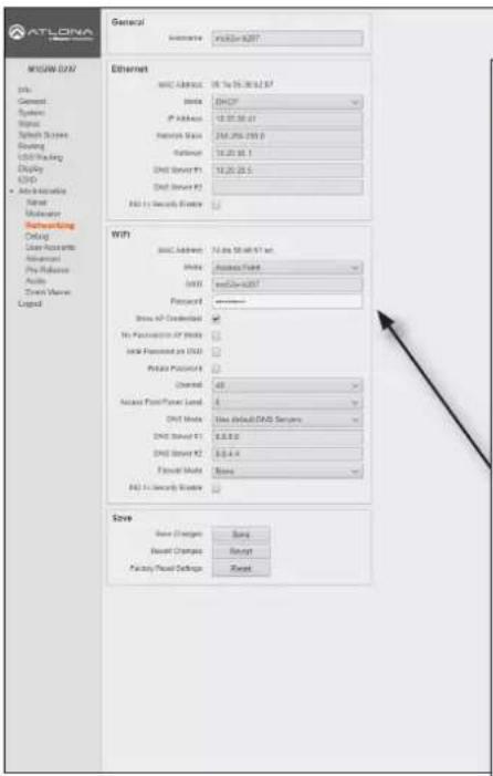
Rotate Password
Click this check box to randomly generate a new password after the specified time interval has expired.
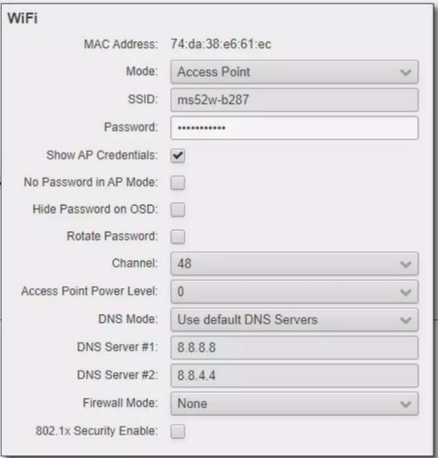
Channel
Click this drop-down list to select the desired wireless channel. Channels 1 through 11 are 2.4 GHz channels.
Channels 36 and above are 5 GHz channels. Contact the network administrator if necessary.
Access Point Power Level
Sets the transmission power of the USB WiFi antennas. Click the drop-down list to select the power level. Available values are integers 0 through 13. Lower values will reduce transmission power of the USB WiFi antenna, thus limiting the range of the Access Point on the AT-OME-MS52W.
DNS Mode
Click this drop-down list to select the desired DNS mode.
DNS Server #1 / DNS Server #2
Enter the DNS server addresses in the DNS Server #1 and DNS Server #2 fields. If the AT-OME-MS52W will be used within an internal LAN, this information is not required.
Firewall Mode
This feature is only available when the WiFi mode is set to Access Point. Click the Firewall Mode drop-down list to select the desired mode. This feature allows control of incoming and outgoing network traffic. The AT-OME-MS52W provides the following firewall modes: Block Private Network, Block Internet, Block All, and None. Refer to Firewall Mode (page 48) for more information.
802.1x Security Enable
Click this checkbox to enable 802.1x authentication mode. When enabled, the RADIUS server, RADIUS port, and RADIUS secret fields will be available. Refer to 802.1X Authentication (page 53) for more information.
Configuration and Management Interfaces
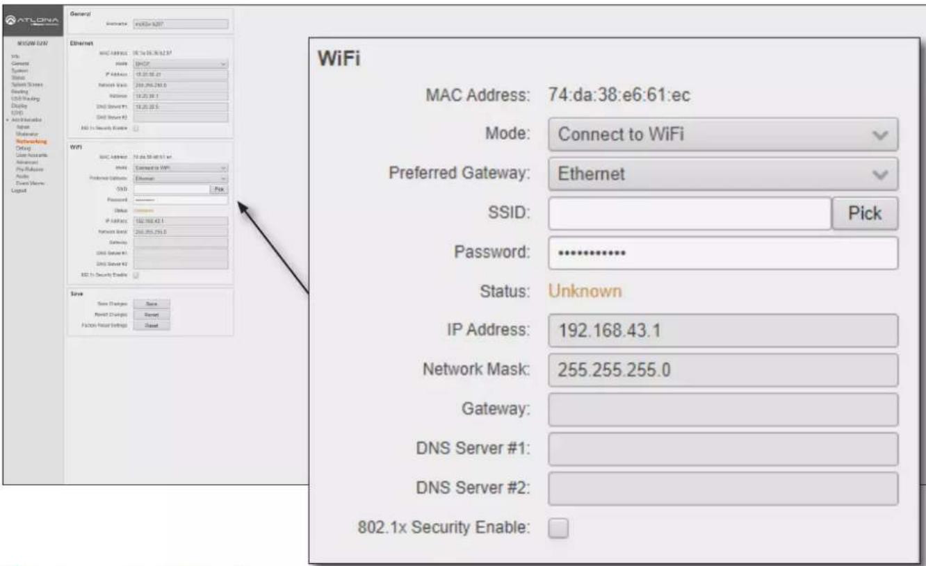
WiFi - Connect to WiFi Mode
Mode
Click this drop-down list to select the desired WiFi mode.
| Setting Description | |
| Access Point Select this option | to configure the AT-OME-MS52W as a Wireless Access Point,allowing other wireless devices to connect to the same wired network as the AT-OME-MS52W. |
| Connect to WiFi Select this mode | to connect the AT-OME-MS52W to the specified SSID of a wireless host. |
| Disabled Select this mode to disable Wi-Fi on the AT-OME-MS52W. | |
Preferred Gateway
When set to Connect to WiFi mode, the AT-OME-MS52W can only be accessed though the same network, over Ethernet or WiFi, not both. For example, if Ethernet is selected, then the AT-OME-MS52W can only be accessed from the same network over Ethernet. However, it should be noted that casting is supported on both interfaces, simultaneously.
SSID
Click the Pick button to display a pop-up dialog displaying all available WiFi networks. Click the desired WiFi network from the list and click the OK button to accept the selection or click Cancel to return without making a WiFi network selection. When a wireless network is selected, its name will appear in the SSID field.
Password
Enter the password required to connect to the wireless network, in this field.
Status
This field indicates the connection state. If no connection is present, then this field will indicate Unknown. Once a valid wireless connection has been established, this field will indicate Connected.
Configuration and Management Interfaces
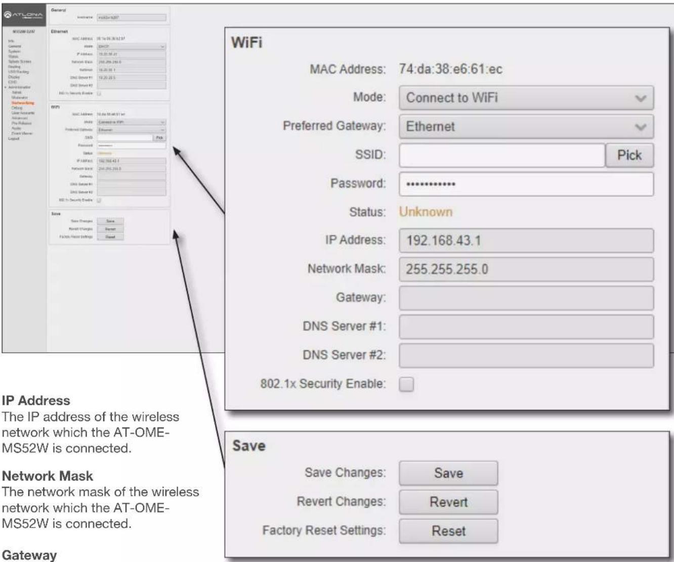
IP Address
The IP address of the wireless network which the AT-OME-MS52W is connected.
Network Mask
The network mask of the wireless network which the AT-OME-MS52W is connected.
Gateway
This field cannot be changed.
DNS Server #1 / DNS Server #2
These fields cannot be changed.
802.1x Security Enable
Click this checkbox to enable 802.1x authentication mode. When enabled, the RADIUS Server, RADIUS Port, and RADIUS Secret fields will be available. Refer to 802.1X Authentication (page 53) for more information.
Save
Save
Click this button to commit changes within the Network menu.
Revert
Click to abort changes.
Reset
Click this button to reset the network settings to factory-default settings.
Configuration and Management Interfaces
Administration > Debug page
Click the Download Logs button to download the debug logs. Debug logs are downloaded in a .zip file. Debug logs are used by Atlona Technical Support Engineers to identify functionality issues.
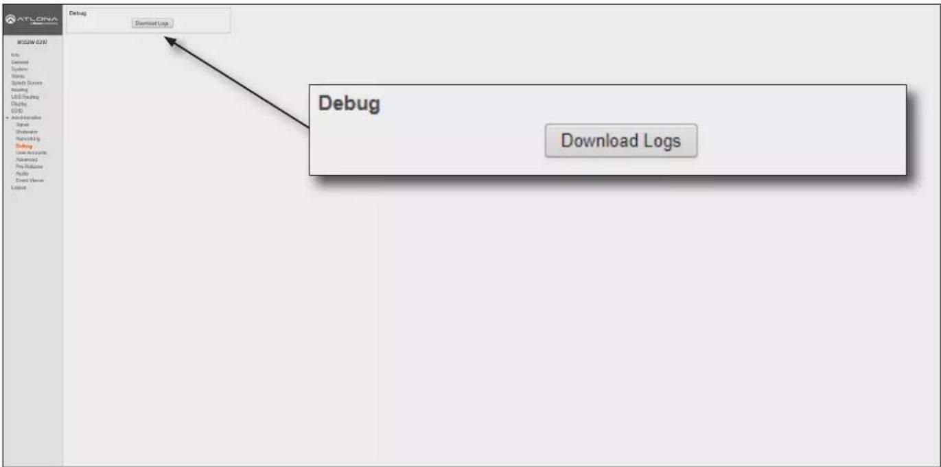
- Click Debug on the side menu bar.
- Click the Downloads Logs button to display the Save As dialog box.
- Browse to the desired folder where the .zip file will be downloaded.
- Click the Save button on the Save As dialog to save the debug log file.
Configuration and Management Interfaces
Administration > User Accounts page
This page allows the default password to be changed.
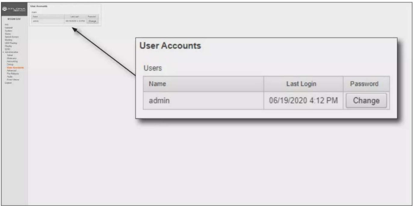
- Click the Change button to display the Change Password dialog box.
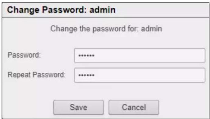
- Enter the new password in the Password field.
- Re-enter the same password in the Repeat Password field.
- Click the Save button to commit changes or click Cancel to abort the process.
Configuration and Management Interfaces
Administration > Advanced page
This page provides options for advanced functionality.
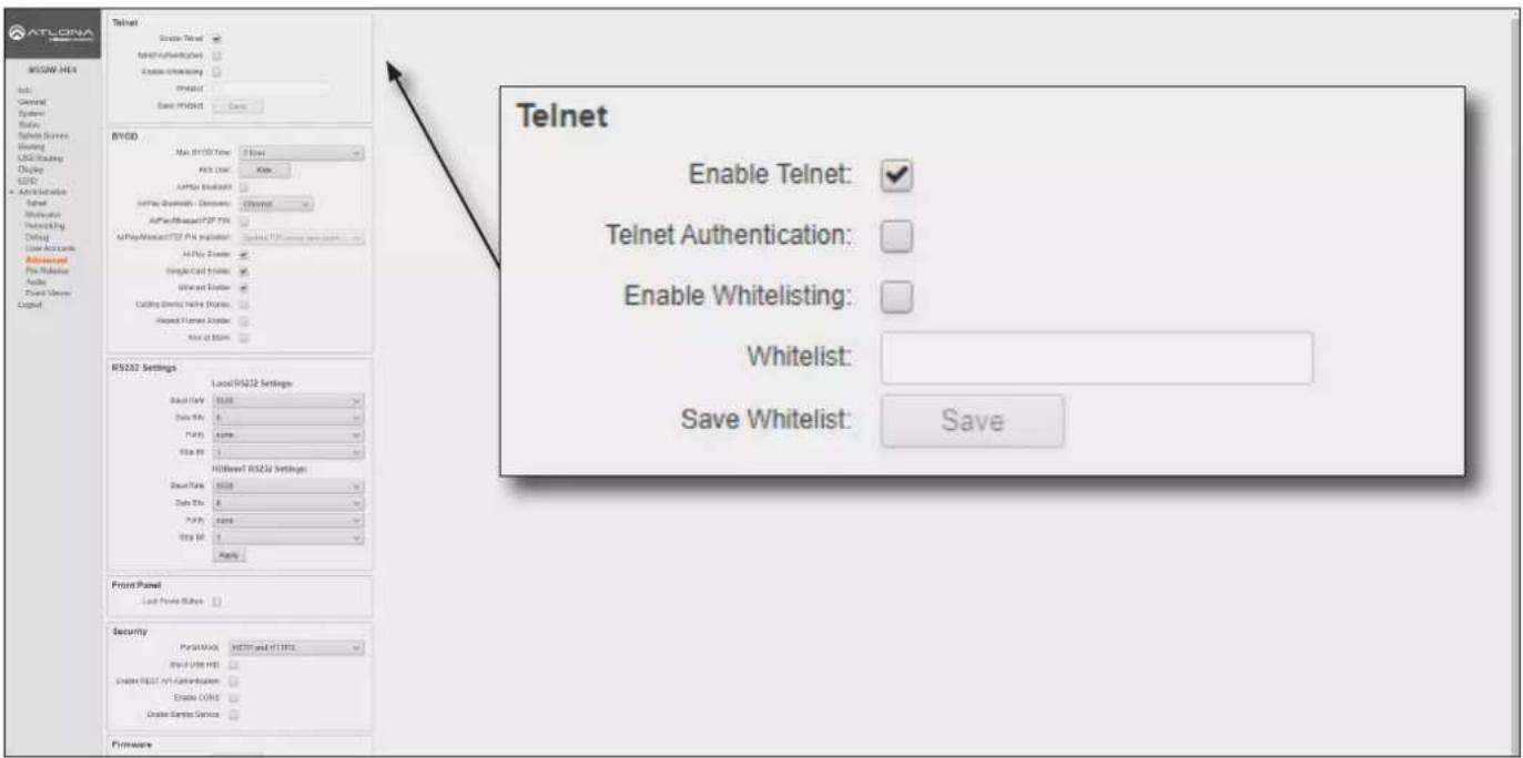
Telnet
Enable Telnet
Click this check box to enable or disable the Telnet protocol for the AT-OME-MS52W. When checked, Telnet is enabled.
Telnet Authentication
Click this check box to enable or disable the Telnet authentication. When checked, Telnet is enabled. When this feature is enabled, username and password credentials will be required at the beginning of the Telnet session.
Enable Whitelisting
Click this check box to enable whitelisting. Whitelisting only allows Telnet access to those users within the specified network. Users outside the network will not be granted access.
Whitelist
Enter the network IP address using CDIR notation (e.g. 192.168.11.1/24), in this field. Multiple network IP addresses can be specified with a comma and space: 192.168.11.1/24, 10.0.1.1/24.
Save Whitelist
Click the Save button to save the whitelist field.
Configuration and Management Interfaces
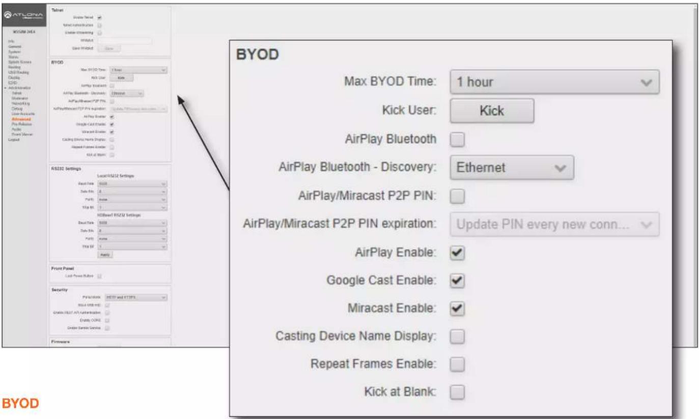
Max BYOD Time
Click this drop-down list to select the desired time interval before the connected BYOD is automatically disconnected from the AT-OME-MS52W. Available options are 35 minutes to 5 hours.
Kick User
Click this button to disconnect the current BYOD.
Airplay Bluetooth - Ethernet
Click this check box to enable Bluetooth discovery when using an Ethernet connection. Refer to AirPlay Bluetooth Discovery (page 62) for more information.
Airplay Bluetooth - WiFi
Click this check box to enable Bluetooth discovery when using a WiFi connection. Refer to Refer to AirPlay Bluetooth Discovery (page 62) for more information.
Airplay/Miracast P2P PIN
Click this check box to allow the ability to add randomized PIN codes when connecting using AirPlay.
Airplay/Miracast P2P PIN expiration
Click this drop-down list to select the time interval before a new PIN code is requested by the system. This drop-down list is only available if the Airplay/Miracast P2P PIN check box is checked.
| Setting Description | |
| Update Pin every new connection | A new PIN code is generated each time a device attempts to connect to the AT-OME-MS52W. |
| Update Pin every 15 minutes A | new PIN is generated every 15 minutes, whether or not a connection request is made. |
| Update Pin every 60 seconds A | new PIN is generated every 60 minutes, whether or not a connection request is made. |
Configuration and Management Interfaces
Airplay Enable
Click this check box to enable AirPlay. This option is enabled by default.
Google Cast Enable
Click this check box to enable Google Cast™. This option is enabled by default.
Miracast Enable
Click this check box to enable Miracast. This option is enabled by default.
Casting Device Name display
Check this box to show the hostname of the casting device on the splash screen.
Kick at Blank
Click this check box to allow the AT-OME-MS52W to kick the wireless BYOD client when the device goes to sleep.
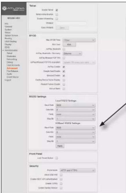
RS232 Settings
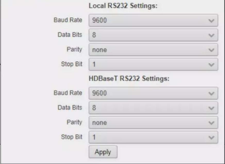
RS232 Settings
Baud Rate, Data Bits, Parity, and Stop Bits
The RS-232 settings for the selected RS-232 mode.
| Setting Description | |
| Baud rate Sets the baud rate. | The following options are available: 9600, 14400, 19200, 38400, 57600, 115200. |
| Data bit Sets the number of data bits used to represent each character of data. | The following options are available: 7 or 8. |
| Parity Sets the parity bit, which can be included with each character to detect errors during the transmission of data. | The following options are available: None, Odd, or Even. |
| Stop bit Sets the stop bit. | Stop bits are sent at the end of each character, allowing the client to detect the end of a character stream. The following options are available: 1 or 2. |
Apply
Click this button to apply changes to the RS232 settings.
Configuration and Management Interfaces
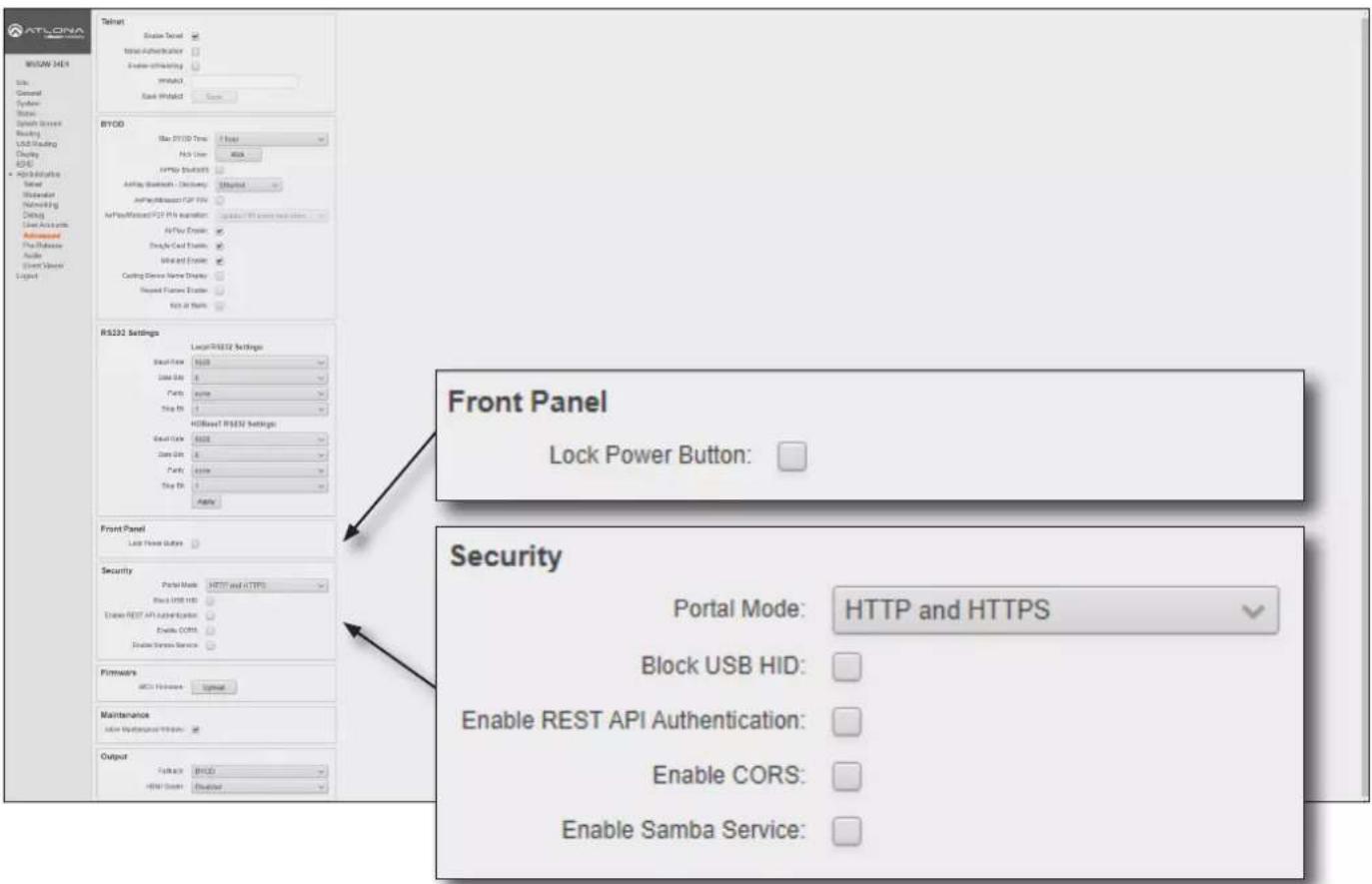
Front Panel
Lock Power Button
Check this box to enable or disable the locking of the POWER button on the front panel. Locking this button will prevent accidental pressing of the POWER button and powering-off the unit.
Security
Portal Mode
Click this drop-down list to select the desired HTTP protocol.
| Setting Description | |
| HTTP and HTTPS Provides either HTTP or HTTPS connections at the login screen. | |
| HTTPS Used for secure connections only. | |
Block USB HID
Deactivates / disables the USB ports on the rear panel of the AT-OME-MS52W.
Enable REST API Authentication
Enables or disables REST authentication when using the AT-OME-MS52W API. Click this check box to enable the feature.
Enable CORS
Check this box to enable Cross-Origin Resource Sharing (CORS). This allows the AT-OME-MS52W to connect with certain servers. CORS is a method which allows restricted resources on a web page to be requested from another domain. Resources can include stylesheets (CSS), scripts, and other embedded elements.
Enable Samba Service
Check this box to enable file and print services for various Microsoft Windows clients using Samba.
Configuration and Management Interfaces
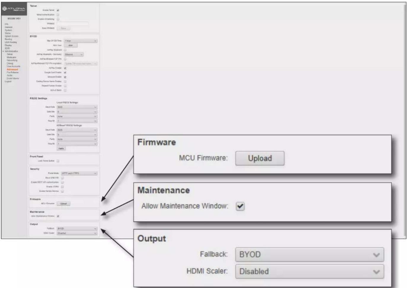
Firmware
Upload
Click this button to upload the latest MCU firmware to the AT-OME-MS52W. Refer to Updating the Firmware (page 115) for more information.
Maintenance
Allow Maintenance Window
Check this box to enable maintenance mode. This feature can only be enabled if the local time has been set. Refer to Setting the System Date and Time (page 22) for more information. When enabled, the system will automatically restart all of its processes at 3:30 AM, every day.
Output
Fallback
This bypasses the default behavior of the system to fallback to the BYOD splash screen. If no video is detected, the AT-OME-MS52W immediately mutes the output instead of falling back to the splash screen.
HDMI Scaler
Click this drop-down list to enable or disable the scaler on the HDMI output. The default setting is disabled.
Configuration and Management Interfaces
Administration > Pre-Release page
This page lists beta features, which are currently in the pre-release / testing stage. It should be noted that these features may not function reliably.
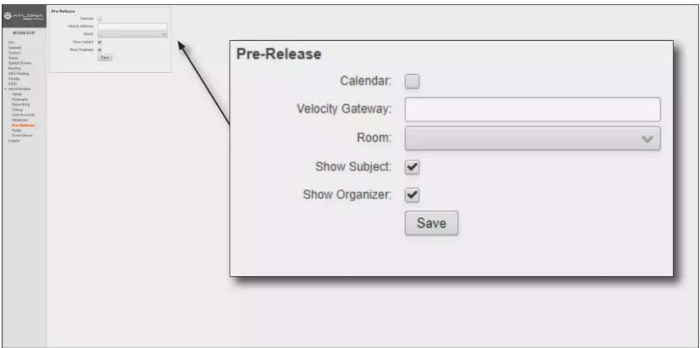
Pre-Release
Features listed under this window group can change between versions. As these features are not officially released, they are not documented.
Configuration and Management Interfaces
Administration > Audio page
This page provides control over the audio output level, as well as selecting analog or digital audio sources for each input.
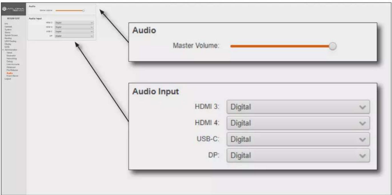
Audio
Master Volume
Click and drag this slider to adjust the output volume. Output is adjustable from -80 to 0 dB.
Audio Input
HDMI 3, HDMI 4, USB-C, DP
Click these drop-down lists to select the desired audio input source. If Analog is selected, then the analog audio source, connected to the 3.5 mm AUDIO IN port, will be heard on that output. Refer to Audio Management (page 61) for more information.
Configuration and Management Interfaces
Administration > Event Viewer page
This page displays a dynamic list of events, returned in JSON format. The image below, shows a list of sample events. This page is useful for monitoring events and troubleshooting the AT-OME-MS52W.
![ATLONA MEGA-021 Info General System Status Switch Devices Routing USB Loading Clutch GHD • Administration Total Bluetooth Networking Outlog User Accounts Advanced Pro-Release Audio Brent Manager Legend [766 - 1592584625858] : {"event":"log":"line":"Total Mem: 1758596 KB, Avai" [767 - 1592584906237] : {"event":"mcuCommand":"wait":false,"cmd":"Versio" [768 - 1592585206238] : {"event":"mcuCommand":"wait":false,"cmd":"Versio" [769 - 1592585225872] : {"event":"log":"line":"Total Mem: 1758596 KB, Avai" [770 - 1592585506238] : {"event":"mcuCommand":"wait":false,"cmd":"Versio" [771 - 1592585806239] : {"event":"mcuCommand":"wait":false,"cmd":"Versio" [772 - 1592585825886] : {"event":"log":"line":"Total Mem: 1758596 KB, Avai" [773 - 1592586106239] : {"event":"mcuCommand":"wait":false,"cmd":"Versio" [774 - 1592586406240] : {"event":"mcuCommand":"wait":false,"cmd":"Versio" [775 - 1592586425900] : {"event":"log":"line":"Total Mem: 1758596 KB, Avai" [776 - 1592586706240] : {"event":"mcuCommand":"wait":false,"cmd":"Versio" [777 - 1592587006241] : {"event":"mcuCommand":"wait":false,"cmd":"Versio" [778 - 1592587025914] : {"event":"log":"line":"Total Mem: 1758596 KB, Avai" [779 - 1592587306241] : {"event":"mcuCommand":"wait":false,"cmd":"Versio" Events [766 - 1592584625858] : {"event":"log":"line":"Total Mem: 1758596 KB, Avai" [767 - 1592584906237] : {"event":"mcuCommand":"wait":false,"cmd":"Versio" [768 - 1592585206239] : {"event":"mcuCommand":"wait":false,"cmd":"Versio" [769 - 1592585225872] : {"event":"log":"line":"Total Mem: 1758596 KB, Avai" [770 - 1592585506238] : {"event":"mcuCommand":"wait":false,"cmd":"Versio" [771 - 1592585806239] : {"event":"mcuCommand":"wait":false,"cmd":"Versio" [772 - 1592585825886] : {"event":"log":"line":"Total Mem: 1758596 KB, Avai" [773 - 1592586106239 ] : {"event":"mcuCommand":"wait":false,"cmd":"Versio" [774 - 1592586406240] : {"event":"mcuCommand":"wait":false,"cmd":"Versio" [775 - 1592586425900] : {"event":"log":"line":"Total Mem: 1758596 KB, Avai" [ 776 - 1592586706240] : {"event":"mcuCommand":"wait":false,"cmd":"Versio" [777 - 1592587006241] : {"event":"mcuCommand":"wait":false,"cmd":"Versio" [778 - 1592587025914] : {"event":"log":"Line":"Total Mem: 1758596 KB, Avai" [779 - 1592587306241] : {"event":"mcuCommand":"wait":false,"cmd":"Versio}](/content/2026/05/896898/images/5cf3246eaa4618c9af49255210677b5ebbfa2daf8decd1c69925a36e5dbae60c.jpg)
Appendix
Updating the Firmware
Updating the firmware is performed using the built-in web server.
Requirements:
- AT-OME-MS52W
-
Firmware files
• Computer on the same network as the AT-OME-MS52W -
Download the firmware from atlona.com and extract the contents of the .zip file to a folder on the computer desktop.
-
Connect an Ethernet cable from the computer, containing the firmware, to the same network where the AT-OME-MS52W is connected.
-
Login to the web server. Refer to Logging in to the Web Server (page 20) for more information.
-
Click System in the side menu bar.
![AT-LONEA MS52W 34.4 File General Systems Basis Sample Series Reading USB Reading Clarity ISO A Administration Legend System Driver Name: MS52W 34.4 Default Default Default Default Default Time System Date / Time: Jul 1, 2012, 16:10 [UTC] • System time read by set as UTC. Find the current time data Local Date / Time: Jul 1, 2012, 16:10 [80:00] MIP/NAV: post-up.org Firmware Model Name: AT-OME-MS52W Master Version: 2.9.6 Firmware Version: 10.2 Update Check: Check Update Firmware: Update Configuration Default: Download Option: Update Documentation User Wizard: Download IT Department Guide: Download API Documentation: Download Firmware Model Name: AT-OME-MS52W Master Version: 2.9.6 Firmware Version: 1.0.23 Firmware Check: Check Update Firmware: Upload • Please do not attempt to downgrade Master or MCU firmware. Firmware Model Name: AT-OME-MS52W Master Version: 2.9.6 Firmware Version: 1.0.23 Firmware Check: Check Update Firmware: Upload • Please do not attempt to downgrade Master or MCU firmware.](/content/2026/05/896898/images/a4a4e96a405b92afe8d90c6aa40f8117e0d0902a57d3778a955ebab5f545a661.jpg)
- Under the Firmware window group, click the Upload button.
- Browse to the location of the SW52-[version].bin firmware file, select it, and click the Open button.
- During the update process, the following message will appear in the upper-right corner of the screen. The unit will automatically reboot as part of the update process.

Server connection lost, trying to reconnect...

IMPORTANT: Note that the firmware update process could take anywhere from 8 to 10 minutes to complete. Do not disconnect power or touch the unit during the firmware update process.
Appendix
- After the firmware process has completed, the AT-OME-MS52W will automatically reboot and the following message will appear at the top of the screen.
Communication problem Take note of any unsaved data, and click here or press ESC to continue.
-
Click the message or press the ESC key to return to the Login screen. Enter the login credentials.
-
The firmware update process is complete.
Mounting Instructions
The AT-OME-MS52W can be mounted in different ways, based on the number of units that are being installed. The AT-OME-MS52W can be mounted in a rack or on/under any flat surface.

NOTE: Rack ears (Altona part no. AT-UHD-SW-510W-RM) are sold separately. Contact Altona for more information.
Single-unit Rack Installation
- Attach the included small rack ear (sold separately) to one side of the AT-OME-MS52W, using the included screws.
- Attach the included longer rack ear (sold separately) to the opposite side of the AT-OME-MS52W using the included screws.
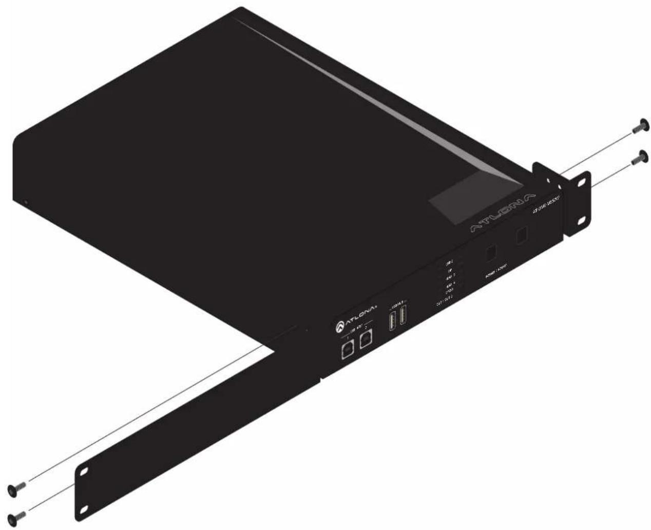
natural_image
Exterior view of a black ATLORA network device with attached cable and connectors (no visible text or symbols on main body)Appendix
Dual-unit Rack Installation
- Turn both units upside-down on a flat surface, next to each other, as shown.
- Position the included mounting plates over the holes on the bottom of the enclosure. When attaching mounting plates, the countersink bevels on the mounting plate should face upward.
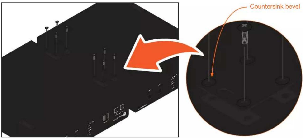
- Turn the attached units over and install the rack ears (sold separately) to one side of each enclosure using the included screws.
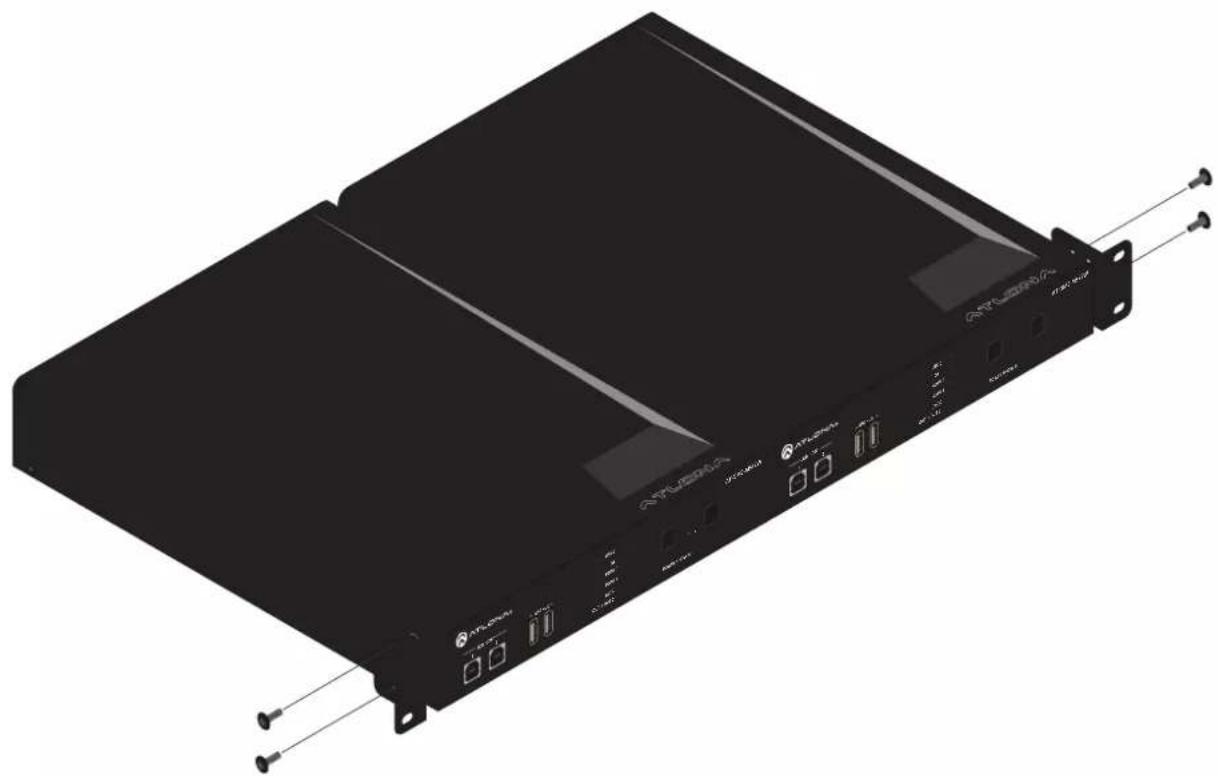
natural_image
3D rendering of a black server rack with attached ports and connectors (no visible text or symbols)Appendix
Flat Surface
-
Turn the unit upside down, on a flat surface.
-
Position the included mounting plates over the pre-drilled holes on the bottom of the enclosure. When attaching mounting plates, the countersink bevels on the mounting plates should face upward.
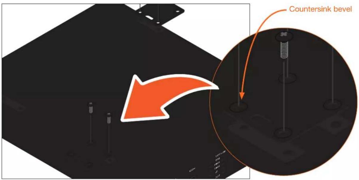
- Mount the unit using the circular holes, on each mounting plate. If using a drywall surface, a #6 drywall screw is recommended. Mounting screws are not included.
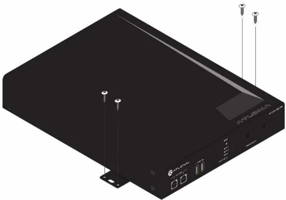
natural_image
Exterior view of a black electronic device labeled 'ATLORA' with ports and screw indicators (no readable text beyond branding)
NOTE: The unit can also be mounted under a flat surface, such as a table, by turning the unit upside down.
Specifications
| Video | ||
| HDMI 2.0 | (2) | |
| HDCP 2.2 (wired-device connections, only) | ||
| UHD/HD | 4096×2160 @ 60^(3) /50/30/25/24 Hz | 1280×720p @ 60/59.94/50 Hz |
| 3840×2160 @ 60^(3) /50/30/25/24 Hz | 720×576p @ 50 Hz | |
| 1920×1080p @ 60/59.9/50/30/29.97 | 720×576i @ 50 Hz | |
| /25/24/23.98 Hz | 640×480p @ 60/59.96 Hz | |
| 1920×1080i @ 30/29.97/25 Hz | 640×480i @ 30 Hz | |
| VESA | 2560×1600 | 1280×800 |
| All resolutions are 60 Hz | 2048×1536 | 1366×768 |
| 1920×1200 | 1360×768 | |
| 1680×1050 | 1152×864 | |
| 1600×1200 | 1024×768 | |
| 1440×900 | 800×600 | |
| 1400×1050 | 640×480 | |
| 1280×1024 | ||
| USB-C(4) | Up to 4K/UHD @ 60 Hz for devices supporting USB-C Alternate Mode video output | |
| Wireless Up to 1080p @ 30 Hz | 4:2:0 (up to 1080p @ 60 Hz with Miracast ^TM ); dependent on wireless signal quality | |
| Color Space YUV, RGB | ||
| Chroma Subsampling 4:4:4, 4:2:2, 4:2:0 | ||
| Color Depth 8-bit, 10-bit, 12-bit | ||
| HDR(5) | HDR10, Hybrid-Log Gamma (HLG), and Dolby® VisionTM @ 60 Hz | |
| Audio | ||
| HDMI / HDBaseT Pass-Through Formats | LPCM 2.0 Dolby® Digital | DTS® Digital SurroundTM |
| Dolby Digital PlusTM | DTS-HD Master AudioTM | |
| Dolby TrueHD | DTS:X® | |
| Dolby Atmos® | ||
| Bit Rate 24 Mbits/s max | ||
| Analog Audio | ||
| Format 2-channel stereo | ||
| Balanced Output +4 dBu, nominal gain; +20 dBu headroom | ||
| Frequency Response 20 Hz to 20 kHz, ±0.5 dB | ||
| THD + N < 0.009% @ 20 Hz to 20 kHz | ||
| SNR > 94 dB @ 1 kHz, zero clipping @ 0 dBFS, unweighted | ||
| Sample Rate 32 kHz, 44.1 kHz, 48 kHz, 88.2 kHz, 96 kHz, 176.4 kHz, 192 kHz | ||
| USB | |
| Signal | 2.0 |
| Maximum Data Rate | 120 Mbps |
| USB-C | Supports Audio, Video, device and host data, and up to 60W power charging |
| USB-C Device Charging Capability | Up to 20 V, 3 AOutput: 60 W @ 20 V, 36 W @ 12 V, 15 W @ 5 V |
| Internal Hubs | 1 USB hub when connected to USB type B host port, 2 cascaded USB hubs when connected to USB-C port |
Appendix
| Protocols | |
| Addressing DHCP, static | |
| Security | HTTPS, SSL, TLS |
| Authentication | IEEE 802.1x |
| Wi-Fi | IEEE 802.11n/ac 2.4 GHz / 5 GHz |
| Wi-Fi Security | WPA, WPA2, PSK |
| Wi-Fi | Frequency Range / Band | Power Output | Number of Channels | Channel Spacing | Modulation Type |
| WLAN (USB Dongle) | 2400 – 2483.5 MHz | 11b (11 Mbps): 16 dBm ±1.5 dBm | 13/9 | 5 MHz | DSSS/OFDM |
| 11g (54 Mbps): 14 dBm ±1.5 dBm | |||||
| 11n (20 MHz, MCS7): 14 dBm ± 1.5 dBm | |||||
| 11n (40 MHz, MCS7): 14 dBm ± 1.5 dBm | |||||
| 5150 – 5825 MHz | 11a (54 Mbps): 12 dBm ±1.5 dBm | 9/2 | 20 MHz | OFDM / QPSK / 16QAM / 64QAM / 256QAM | |
| 11n (20 MHz, MCS7): 12 dBm ± 1.5 dBm | |||||
| 11n (40 MHz, MCS7): 12 dBm ± 1.5 dBm | |||||
| 11ac (80 MHz, MCS9): 10 dBm ± 1.5 dBm |
| Control | ||
| RS-232 Device control and configuration | ||
| IP Protocols: HTTPS, Telnet, mDNS | ||
| CEC Yes | ||
| Resolution / Distance 4K/UHD - Feet / Meters 1080p - Feet / Meters | ||||
| HDMI IN/OUT 15 5 30 10 | ||||
| CAT5e 295 90 330 100 | ||||
| CAT6/6a/7 330 100 330 100 | ||||
Appendix
| Connectors | |
| HDMI IN | 2 - Type A, 19-pin female |
| HDMI OUT | 1 - Type A, 19-pin female |
| DP IN | 1 - 20-pin female |
| USB-C IN | 1 - USB Type-C v3.1, 24-pin female, AV input (Alternate Mode) |
| USB | 3 - USB 2.0 Type A for Wi-Fi® antenna modules |
| USB HOST | 2 - Type B, female |
| USB HUB | 2 - Type A, 4-pin female |
| RS-232 | 1 - 3-pin captive screw (bidirectional) |
| RELAY | 1 - 3-pin captive screw, normally open (NO), with adjustable Toggle and Pulse modes; Electrical rating: 48 V @ 1 A (max.) |
| TRIGGER I/O | 1 - 4-pin captive screw, supports 3 - 30 V DC input range, power supply is 24 V @ 100 mA max. |
| AUDIO IN | 1 - 3.5 mm, unbalanced 2-channel |
| AUDIO OUT | 1 - 5-pin captive screw, balanced / unbalanced 2-channel |
| HDBaseT OUT(5) | 1 - RJ45 |
| LAN | 1 - RJ45, 10/100/1000 Mbps |
| DC 24V | 1 - 4-pin DIN, locking |
| Indicators and controls | |
| Output IndicatorsUSB-C, DP, HDMI 3, HDMI 4,BYOD | 5 - LED, blue (OUT1: HDMI)5 - LED, blue (OUT2: HDBaseT) |
| Control Buttons 4 - momentary | tact-typePOWER: Power-off the unitSHOW IP: Displays the IP address of the unit on the connected displayIP MODE: Toggles IP modeRESET: Resets the unit to factory-default settings |
| Environmental Fahrenheit Celsius | |
| Operating Temperature +32 to +122 °F 0 to 50 °C | |
| Storage Temperature -4 to +140 °F -20 to 60 °C | |
| Operating Humidity (RH) 20% to 90%, non-condensing | |
| Power | ||
| Consumption | 143 W | |
| External Power Supply | 100 - 240 V AC, 50/60 HzOutput: 24 V / 6.25 A DC | |
| Dimensions Inches Millimeters | ||
| Device (H x W x D) 1.65 x 8.62 x 10 42 x 219 x 254 |
| Weight | Pounds | Kilograms |
| Device | 3.89 | 1.77 |
| Certification | ||
| Device CE, FCC | ||
| Power CE, FCC, UL | ||
| Compliance | ||
| NDAA-899 Yes | ||
(1) 18 Gbps supported for HDMI 2.0 output.
(2) HDMI output supports 4K/UHD @ 50 or 60Hz with 4:4:4 chroma sampling. HDBaseT output supports 4K/UHD @ 50 or 60 Hz with 4:2:0 chroma subsampling.
(3) USB-C does not support the following input resolutions: 2560x2048, 2048x1536, 2028x1080, and 1440x1050.
(4) HDR not supported on HDBaseT output.
(5) Maximum limit of 6 USB hubs when traversing an HDBaseT link.
- for HDMI, USB-C, DisplayPort, and HDBaseT™ with USB and Wireless Link
- Version Information
- Sales, Marketing, and Customer Support
- Operating Notes
- Warranty
- Safety and Certification
- CAUTION
- FCC Compliance
- Copyright, Trademark, and Registration
- Table of Contents
- Configuration and Management Interfaces 77
- Appendix 115
- Introduction
- Features
- Package Contents
- Panel Description
- USB HOST
- USB HUB
- OUT 1 / OUT 2 LED Indicators
- POWER
- SHOW IP
- IP MODE
- RESET
- INPUT (USB-C)
- AUDIO
- INPUT (HDMI)
- USB HUB
- OUTPUT (HDMI)
- OUTPUT (HDBaseT)
- RELAY
- TRIGGER I/O
- LAN
- RS-232
- DC 24V
- Installation
- Connectors
- RS-232
- Audio
- Relay
- Trigger I/O
- Connection Instructions
- IP Configuration
- Getting the IP Address
- Getting the IP Address without a Display
- Switching the IP Mode Using the Front Panel
- Auto IP Mode
- Setting the IP Address using the Web Server
- Resetting to Factory-Default Settings
- Device Operation
- LED Indicators
- Logging in to the Web Server
- Login Registration
- Logging in after registration
- Setting the System Date and Time
- Automatic Adjustment
- Document Tools: Download
- Setting Local Date and Time
- Using an NTP Server
- Selecting the Input
- Switching Modes
- Matrix Mode
- Matrix Mode w/ Static Route
- Auto-Switching
- Enabling / Disabling Auto Switching
- USB Modes
- Manual
- Auto Switch
- Follow Video Input
- The Splash Screen
- Customizing Text
- Displaying Metadata
- Displaying the Wireless Password
- Cycling Background Images
- Uploading Custom Images
- HTML Splash Screens
- Downloading the default splash screen
- Using a custom HTML file
- Resetting the HTML Splash Screen
- Wireless Configuration
- Access Point Mode
- Firewall Mode
- Connect to WiFi Mode
- Changing the SSID
- 802.1X Authentication
- Ethernet Connections
- WiFi Connections
- Casting
- iOS Devices
- OS X Devices
- - Mirroring
- - Extending
- - Turning Off AirPlay
- Microsoft Miracast
- Method 1
- Method 2
- Google Chrome
- Audio Management
- Using External Audio Sources
- Controlling Audio Output Volume
- AirPlay Bluetooth Discovery
- AirPlay / Miracast P2P PIN Codes
- Restart AirPlay/Miracast/Google Cast
- Changing the PIN Timeout
- Moderator Mode
- Display Control Methods
- Active Video Presence
- Active Video Presence with Occupancy Sensor
- Occupancy Sensor Control
- Occupancy Sensor
- Day and Time
- Access Point
- Changing the Password
- Configuration and Management Interfaces
- Web Server
- Login Register page
- User
- Password
- Confirm
- Register
- Login page
- Login
- Secure Login
- Info page
- Info
- Model Name
- UTC Date / Time
- Master Version
- Firmware Version
- HDBaseT Version
- General
- Name
- Display Name
- Derived
- Save
- Revert
- Restart
- Shutdown
- Factory Reset
- Time
- NTP Server
- Displayset Tools:
- Firmware
- Download
- Firmware Check
- Update Firmware
- Configuration
- Upload
- Documentation
- User Manual
- IT Deployment Guide
- API Documentation
- Status
- Splash Screen page
- Splash Screen
- Type
- Show Meta Data
- Show Panel
- Y Offset
- Title
- Subtitle
- Column Title
- Column #1
- Show Second Column
- Column #2
- Footer
- Legend
- Images
- Reset Splash Images
- Enable Image Rotation
- Image Rotation Time
- Routing page
- Input Selection
- Matrix Switching
- Matrix Switch
- Fallback to Static Source
- USB Routing
- USB Routing Mode
- Control
- AutoSwitch
- Display Control Method
- Lamp cool down timer
- Display Warm-Up Timer
- Auto power off timer
- Control Type
- Volume / Mute
- CEC Commands
- Enable Momentary Relay
- Relay Pulse Duration
- Enable Trigger On
- Enable Trigger Off
- RS-232 Mode
- RS-232/IP Commands
- Manufacturer
- Products
- Model
- Display Commands
- EDID
- EDID (Extended Display Identification Data)
- Inputs
- Administration > Moderator page
- Moderator
- Enable
- Users
- Administration > Networking page
- Hostname
- Ethernet
- MAC Address
- Mode
- IP Address
- Network Mask
- Gateway
- DNS Server #1 / DNS Server #2
- 802.1x Security Enable
- WiFi - Access Point Mode
- SSID
- Show AP Credentials
- Hide Password on OSD
- Rotate Password
- Channel
- Access Point Power Level
- DNS Mode
- Preferred Gateway
- Reset
- Administration > Debug page
- Telnet
- Enable Telnet
- Telnet Authentication
- Enable Whitelisting
- Whitelist
- Save Whitelist
- Max BYOD Time
- Kick User
- Airplay Bluetooth - Ethernet
- Airplay Bluetooth - WiFi
- Airplay/Miracast P2P PIN
- Airplay/Miracast P2P PIN expiration
- Airplay Enable
- Google Cast Enable
- Miracast Enable
- Casting Device Name display
- Kick at Blank
- RS232 Settings
- Baud Rate, Data Bits, Parity, and Stop Bits
- Apply
- Front Panel
- Lock Power Button
- Security
- Portal Mode
- Block USB HID
- Enable REST API Authentication
- Enable CORS
- Enable Samba Service
- Maintenance
- Allow Maintenance Window
- Output
- Fallback
- HDMI Scaler
- Administration > Pre-Release page
- Pre-Release
- Administration > Audio page
- Master Volume
- Audio Input
- HDMI 3, HDMI 4, USB-C, DP
- Administration > Event Viewer page
- Appendix
- Updating the Firmware
- Requirements:
- Mounting Instructions
- Single-unit Rack Installation
- Dual-unit Rack Installation
- Flat Surface
Brand : Atlona
Model : Omega AT-OME-MS52W
Category : Router