
FMD 2001 - Loudspeaker FBT - Free user manual and instructions
Find the device manual for free FMD 2001 FBT in PDF.


| Product Type | Active PA Speaker |
| Brand | FBT |
| Model | FMD 2001 |
| Dimensions (W x H x D) | 400 x 600 x 350 mm |
| Weight | 15 kg |
| Power Output (RMS) | 400 W |
| Frequency Response | 50 Hz – 20 kHz |
| Impedance | 8 ohms |
| Sensitivity | 97 dB (1W/1m) |
| Maximum SPL | 123 dB |
| Input Connectors | XLR, 1/4" Jack, RCA |
| Output Connectors | XLR Link |
| Amplifier Type | Class D |
| Woofer Size | 12" (300 mm) |
| Tweeter Size | 1" (25 mm) compression driver |
| Enclosure Material | Plywood with polyurea coating |
| Grille Material | Steel with acoustic foam |
| Power Supply | AC 100-240V, 50/60 Hz |
| Protection Features | Overload, thermal, limiter |
| Mounting Options | Pole mount, floor monitor angle |
| Operating Temperature | 0°C – 40°C |
| Included Accessories | Power cable, user manual |
Frequently Asked Questions - FMD 2001 FBT
User questions about FMD 2001 FBT
0 question about this device. Answer the ones you know or ask your own.
Ask a new question about this device
Download the instructions for your Loudspeaker in PDF format for free! Find your manual FMD 2001 - FBT and take your electronic device back in hand. On this page are published all the documents necessary for the use of your device. FMD 2001 by FBT.
USER MANUAL FMD 2001 FBT
natural_image
Two black electronic devices with earphones and control panels, one emitting a microphone (no visible text or symbols)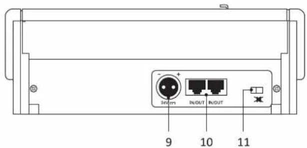
Fireman Microphone Desktop
| ○▶ FAULT | ALARM |
| ○▶ FAULT COM. | LOCAL POWER |
| ○▶ FAULT UNIT | REMOTE POWER |
| ○▶ DISABLE | RUN [SET] |
| ○▶ BUSY |
3.4 Chiamate broadcast
FMD 2001 and FMD 2012 remote stations for emergency calls enable live or recorded alert or evacuation messages to be sent out using a controlled microphone. The LEDs on the front panel provide the main information on the status of the emergency system and on any failures.
These remote stations, designed specifically for the VAIE 2250 system, are of two different types: the FMD 2001 station enables a single All-Call to be made; if the alarm messages have to be sent to separate zones, on the other hand, it will be necessary to use the FMD 2012 station, which enables a maximum of 12 zones to be selected.
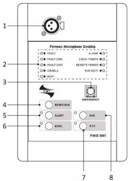
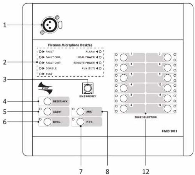
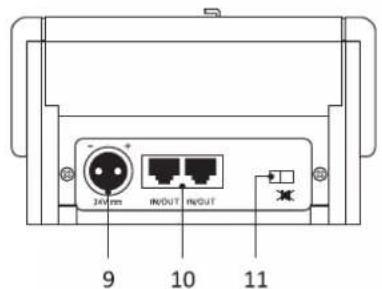
1.1 Numbered references
- Socket for stem or hand-held microphone.
- Status-indicator LEDs.
- Emergency key.
- Key for interrupting message/failure buzzer.
- Key for sending out pre-recorded alert message.
- Key for sending out pre-recorded evac messages.
- Call key.
- Key for calling up pre-set messages.
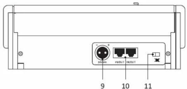
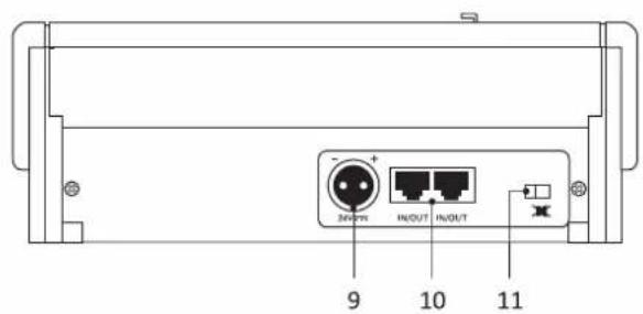
- Connector for external 24 VDC power supply.
- IN/OUT connectors.
- Buzzer switch (see note on page 22).
- Zone-selection keys with status-indicator LED (FMD 2012 only).
Each station must be completed with an additional microphone (not included in the supply) to be chosen from among the following models:

FMG 2000
Dynamic gooseneck microphone
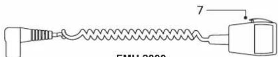
Dynamic hand-held microphone with P.T.T. key
UK
CONNECTIONS
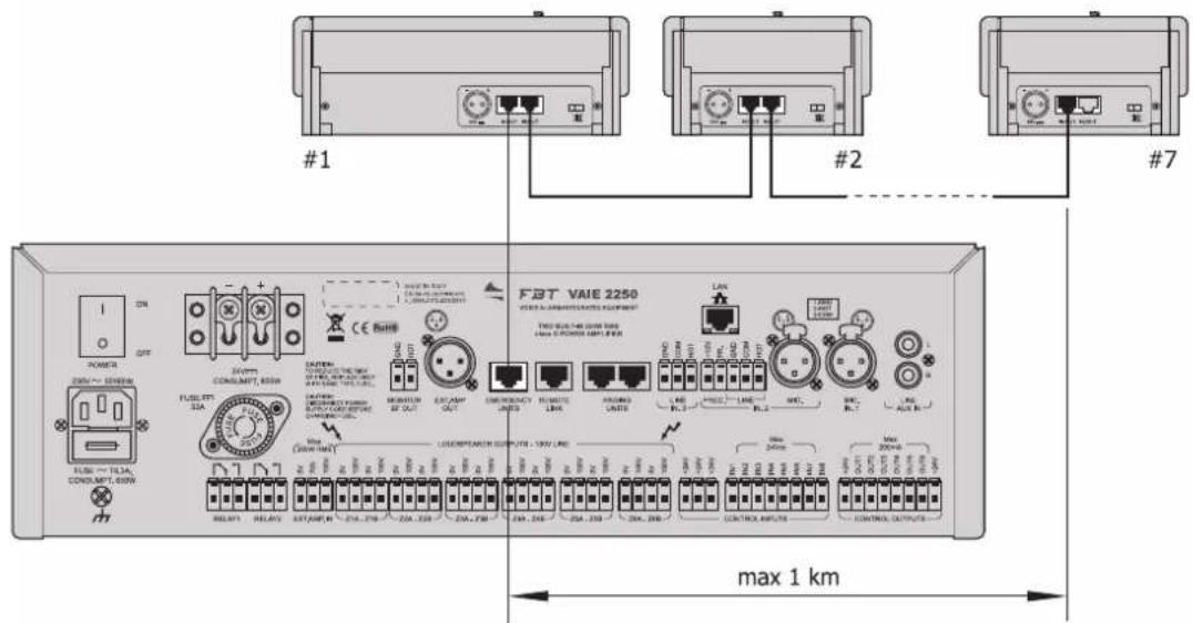
FMD 2001 and FMD 2012 stations must be connected to the 'EMERGENCY UNITS' of the VAIE 2250 system. It is possible to connect up to 7 remote stations in cascade formation by means of the IN/OUT (10) sockets provided for this purpose, which can be used as inputs or outputs as required. Special attention must be paid to assigning correctly the logical addresses to each station (see point 4.1, "Address", page 19).
The connections to the stations are made by means of CAT5e SF/UTP shielded cable and a shielded STP connector. For these cables EIA/TIA T568A and EIA/TIA T568B (and the associated RJ45 connectors) standards require the pinouts and colour schemes shown in the table:
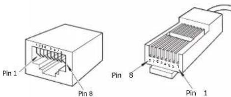
The table also shows the pinouts for the IN/OUT connectors (10).
N.B.!
Cross-cables are not permitted.
All the connectors must be shielded RJ45 connectors.
| T568A T568B IN/OUT | |||
| PIN Colour Colour Function | |||
| 1 White/Green White/Orange Audio + | |||
| 2 Green Orange Audio - | |||
| 3 White/Orange White/Green GND | |||
| 4 Blue | Blue | Not connected | |
| 5 White/blue | White/Blue | Not connected | |
| 6 Orange Green +Vdc | |||
| 7 White/Brown | White/Brown | Serial + | |
| 8 Brown | Brown | Serial - | |
| Shield | Shield Shield GND | ||
2.1 Sizing
Using shielded CAT5e SF/UTP cable, it is possible to apply the following limits:
1 station = total length max 300m
2 stations = total length max 200m
3 stations = total length max 100m
For systems with more than 3 stations connected to them, at distances greater than those indicated above, each station will also have a local power supply providing a continuous stabilised current of 24V_dc/500mA , using the socket provided for this purpose on the rear (9).
UK
USE
FMD 2001 and FMD 2012 stations are equipped with a set of LEDs for signalling the operating states of the system.
Following are details of the LED's and the corresponding statuses.
Fireman Microphone Desktop
| ○▶ FAULT | ALARM |
| ○▶ FAULT COM. | LOCAL POWER |
| ○▶ FAULT UNIT | REMOTE POWER |
| ○▶ DISABLE | RUN [SET] |
| ○▶ BUSY |
| FAULT Yellow | This indicates a generic “failure status” within the system.See the FAULTS menu of the VAIE 2250 to identify the failed components. | ||
| FAULT COM. Yellow | This indicates a lack of communication of data between the station in question and the VAIE 2250. See the FAULTS menu of the VAIE 2250 to identify the failed | ||
| FAULT UNIT Yellow | This indicates a generic failure of the station in question.See the FAULTS menu of the VAIE 2250 to identify the failed components. | ||
| DISABLE Yellow | This signals an active “disabled status”. It indicates the presence of at least one zone to which sending of emergency messages is not envisaged. | ||
| BUSY Yellow | This LED flashes on stand-by: it indicates that another station with a lower priority is occupying the system.Flashing: during a broadcast call, it indicates the duration of the chime signal.Steady ON: this indicates that another station with a higher priority is occupying the system. | ||
| ALARM Red This indicates an “alarm status” existing within the system. | |||
| LOCAL POWER Green | This indicates the presence of the local DC power supply applied to the external socket of the station. | ||
| REMOTE POWER Green | This indicates the presence of the power supply provided by the VAIE 2250 through the CAT5 cable. | ||
| RUN/SET Green | Flashing: this indicates that the station is working correctly and operating normally.Steady: this indicates that the station configuration stages is active (SET). | ||
N.B.: For further information about the operating states of the system, consult the “Operating conditions and Terminology” section of the VAIE 2250 manual.
Various different types of use can be identified:
- Sending of emergency messages in the live mode.
- sending of pre-recorded evacuation/alert messages.
- Broadcast calls.
• Zone selection (FMD 2012 only). - AUX function for calling up pre-configured messages.
- Resetting of emergency messages.
- Resetting the failure acknowledgement buzzer (ACK).
3.1 Manual emergency activation
To activate this procedure, press the EMERGENCY key (protected by a cover): as soon as the emergency procedure has been activated, the system switches automatically to the All-Call mode.
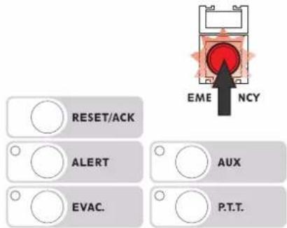
Fig. 3.1.1
It is possible to activate the emergency procedure only if the priority conditions as assigned enable this.
UK
USE
An existing emergency status can be stopped only from a station with a higher priority.
The red LED indicates the conditions of the system:
• off = manual emergency procedure de-activated.
- flashing = manual emergency procedure activated by another station. The P.T.T., ALERT, EVAC, RESET and AUX keys are not operational.
- steady ON = manual emergency activated by the station. The P.T.T., ALERT, EVAC, RESET and AUX keys can be used to manage the emergency.
3.2 Sending live emergency messages
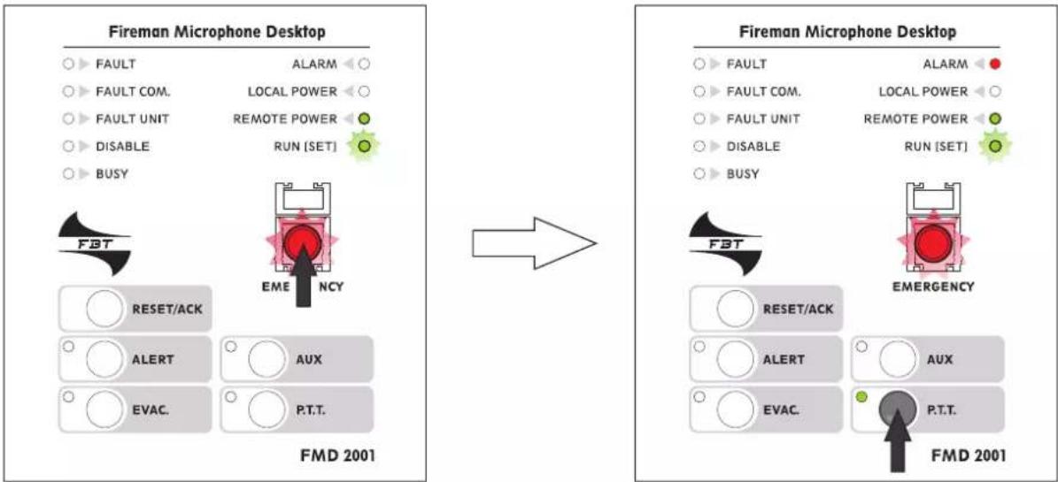
After activating the emergency procedure (Fig. 3.2.1), press the P.T.T. key: the red ALARM LED will light up. The green P.T.T. LED will also light up and it will be possible to speak into the microphone (Fig. 3.2.1).
The P.T.T. key has priority over any pre-recorded messages being sent out.
To terminate the live emergency message, release the P.T.T. key and press the EMERGENCY key again, taking care to close the cover again.
flowchart
graph LR
    subgraph_Fireman_Microphone_Desktop["Fireman Microphone Desktop"]
        A1["FAULT"] --> B1["ALARM"]
        A2["FAULT COM."] --> B2["LOCAL POWER"]
        A3["FAULT UNIT"] --> B3["REMOTE POWER"]
        A4["DISABLE"] --> B4["RUN (SET)"]
        A5["BUSY"] --> B5["EME NCY"]
        B5 --> C1["RESET/ACK"]
        B5 --> C2["ALERT AUX"]
        B5 --> C3["EVAC P.T.T."]
        C1 --> D1["FMD 2001"]
        C2 --> D2["FMD 2001"]
        C3 --> D3["FMD 2001"]
        D1 --> E1["EMERGENCY"]
        D2 --> E2["FMD 2001"]
        D3 --> E3["FMD 2001"]
    end
Fig. 3.2.1 Fig. 3.2.2
3.3 Sending pre-recorded emergency messages
To send pre-recorded alert or evacuation messages stored in the memory of the VAIE 2250, after activating the emergency mode (Fig. 3.1.1), press ALERT or EVAC. (Fig. 3.3.1) to send out the alert message or the evacuation message. The ALARM LED will light up and the corresponding yellow LED (ALERT) or red LED (EVAC) will light up by way of confirmation.
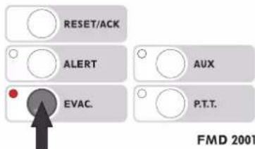
Fig. 3.3.1
3.4 Broadcast calls
It is also possible to make a livel call without the emergency mode. To do this, simply press the P.T.T. key and speak into the microphone. Activation will be confirmed by the corresponding green LED lighting up. To end the call, release the key.
Note
- Before making a broadcast call, check the status of the BUSY LED to see whether the line is being used by another station. After pressing the P.T.T. key, wait for the yellow BUSY LED to extinguish (it flashes while the chime tone is sounding).
- In the broadcast mode, FMD 2001 and FMD 2012 stations will always have a higher priority than any other broadcasting sources and stations of the MBT 1106/MBT 1112 range connected to the VAIE 2250.
UK
USE
3.5 Zone selection (FMD 2012 only)
The FMD 2012 has a key pad to be used for pre-selecting one or more zones to which handsfree messages can be sent or pre-recorded messages can be sent/reset. Each key has three LEDs that indicate the status of the zone concerned:
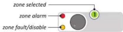
| LED Status Indication | ||
| Zone selected (green) | Flashing Zone selected | |
| Steady ON (in an emergency status) with the “zone alarm” LED illuminated | Live emergency announcement being sent out | |
| Steady ON (in the broadcasting status) Live announcement being broadcast | ||
| Zone alarm (red) | Flashing ALERT message being sent out | |
| Steady ON, with the “zone selected” LED OFF EVAC message being send out | ||
| Zone fault/disable (yellow) | Flashing | - Line failed or- Line not available due to amplifier failure |
| Steady ON Line set in “disabled status” | ||
• to send selective live messages
After activating the emergency mode (see Fig. 3.1.1), press the keys corresponding to the zones concerned. Only the green LED's of the selected zones will light up to indicate the booking (Fig. 3.5.1), while the others will extinguish. Press the P.T.T. key and hold it down. The green and red LEDs corresponding to the activated zones will light up and remain steady ON and it will be possible to speak into the microphone to send the handsfree emergency message only to the zones that have been selected (in the example in Fig. 3.5.2, these are zones 1-2-3-5-10-12). On releasing the key, the All-Call mode will be activated automatically (all the green LEDs will flash).
![ALARM LOCAL POWER REMOTE POWER RUN [SET] EMERGENCY AUX P.T.T.](/content/2026/05/896340/images/a514ae6a56901bd9f85b0631e6c4d9bc021292a9577e7a67a70409bd1cdaf868.jpg)
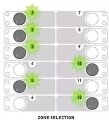
Fig. 3.5.1
• to send selective pre-recorded messages
After activating the emergency mode (see Fig. 3.1.1), press the keys corresponding to the zones concerned. Only the green LED's of the selected zones will light up to indicate the booking (Fig. 3.5.1). Then press ALERT or EVAC to send the alert or evacuation message only to those zones that have been selected. Activation will be confirmed by the red LED corresponding to the zones in question:
LED steady ON = EVAC
Led flashing = ALERT
Once the message has been sent out, the All-Call mode will be activated automatically (all the green LEDs will flash).
• to send selective messages in the broadcast mode
Select the required zones. The LEDs corresponding to the selected zones will light up. Then follow the instructions provided under point 3.4. The zone LEDs will light up steadily to confirm the activation.
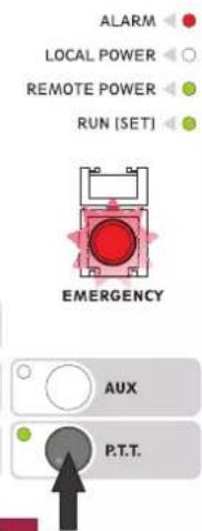
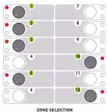
Fig. 3.5.2
UK
USE
3.6 AUX function
The AUX function can be used to call up a specific combination of messages/broadcasting zones set previously via the VAIE 2250. To do this, enter the emergency mode (Fig. 3.1.1), then press the AUX key.
The green AUX LED will light up to confirm activation. The red ALARM LED and those indicating the type of message sent (ALERT or EVAC) will light up to indicate the existing alarm.
If a FMD 2012 station is used, the LEDs referred to the zones concerned will also light up.
Once the messages have been sent out, press EMERGENCY again to leave the emergency mode, then close the cover again.
![FAULT FAULT COM. FAULT UNIT DISABLE BUSY FBT RESET/ACK ALARM LOCAL POWER REMOTE POWER RUN [SET] EMERGENCY AUX EVAC. P.T.T.](/content/2026/05/896340/images/b16feb005f96c29cb24d8cab666f86a9faedbf58357edd0b86726185cc018274.jpg)
Fig. 3.6.1
3.7 RESET/ACK function
The RESET/ACK key has multiple functions depending on the status of the system:
Message RESET (RESET function)
- ALL-CALL: When there is an on-going alarm and with the station in the emergency mode, hold the RESET/ACK key down for 2 seconds. This will enable the messages to be stopped, although the system will remain in an emergency status.
- PARTIAL: when there is an on-going alarm and with the station in the emergency mode, select the zones to be muted and hold the RESET/ACK key down for 2 seconds.
Resetting the failure acknowledgement buzzer (ACK function)
- In the event of failures with the station on stand-by, press the RESET/ACK key briefly. The buzzer will be reset only on the actual base, while the LEDs corresponding to the failure in question will remain ON.
- In the event of failures, press the EMERGENCY key to enter the emergency mode. Then press the RESET/ACK key briefly. The buzzer will be reset on all the devices of the system. The LEDs referred to the failure in question will in any case remain ON.

SETTINGS
4.1 Address
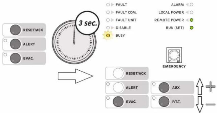
Each station must have its own individual address. To set these addresses press the ALERT, EVAC and RESET/ACK keys simultaneously, holding them down for more than 3 seconds.
flowchart
graph TD
    A["3 sec."] --> B["RESET/ACK"]
    A --> C["ALERT"]
    A --> D["EVAC."]
    A --> E["FAULT COM."]
    A --> F["FAULT UNIT"]
    A --> G["DISABLE"]
    A --> H["BUSY"]
    A --> I["ALARM"]
    A --> J["LOCAL POWER"]
    A --> K["REMOTE POWER"]
    A --> L["RUN (SET)"]
    A --> M["EMERGENCY"]
    M --> N["AUX"]
    M --> O["P.T.T."]
    N --> P["+"]
    O --> Q["-"]
When the RUN/SET LED stops flashing and remains steady ON, release the keys.
There are 7 addresses at disposal, from 1 to 7.
Press the EVAC. key. The LEDs will show the current address setting (factory default setting: 1).
To change an address, hold the EVAC key down, then press AUX (to increase the number) or P.T.T. (to decrease it). The LEDs corresponding to the addresses are shown in the following table.
| ADDRESS | |||||||
| 1 2 3 4 5 | 6 7 | ||||||
| LED | ○▶ FAULT○▶ FAULT COM.○▶ FAULT UNIT○▶ DISABLE●▶ BUSY | ○▶ FAULT○▶ FAULT COM.○▶ FAULT UNIT● ○ DISABLE○▶ BUSY | ○▶ FAULT○▶ FAULT COM.○▶ FAULT UNIT● ▶ DISABLE●▶ BUSY | ○▶ FAULT○▶ FAULT COM.●▶ FAULT UNIT○▶ DISABLE○▶ BUSY | ○▶ FAULT○▶ FAULT COM.●▶ FAULT UNIT○▶ DISABLE●▶ BUSY | ○▶ FAULT○▶ FAULT COM.●▶ FAULT UNIT● ▶ DISABLE○▶ BUSY | ○▶ FAULT○▶ FAULT COM.●▶ FAULT UNIT● ▶ DISABLE●▶ BUSY |
To leave the Settings mode and save the settings made, press the ALERT, EVAC and RESET/ACK keys again. The RUN/SET key will start flashing again.
If you do NOT want to save the changes made, simply wait for the timeout (about 10 seconds), after which the previous settings will be restored.
UK
SETTINGS
4.2 Priority
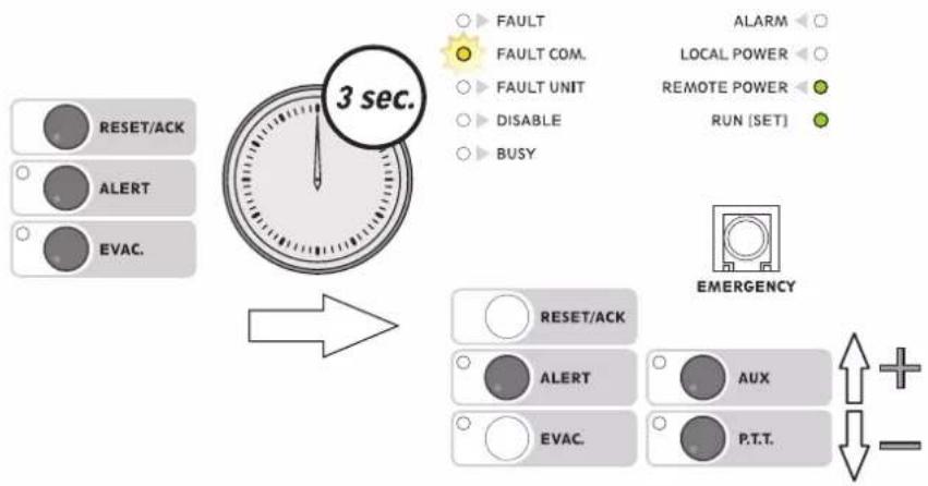
To set the priority of a station, it is necessary to press the keys ALERT, EVAC and RESET/ACK simultaneously for more than 3 seconds. When the RUN/SET LED stops flashing and remains steady ON, release the keys. There are seven priority levels at disposal (from 8 = lowest priority to 14 = highest priority).
flowchart
graph TD
    A["3 sec."] --> B["RESET/ACK"]
    A --> C["ALERT"]
    A --> D["EVAC."]
    A --> E["FAULT COM."]
    A --> F["FAULT UNIT"]
    A --> G["DISABLE"]
    A --> H["BUSY"]
    A --> I["ALARM"]
    A --> J["LOCAL POWER"]
    A --> K["REMOTE POWER"]
    A --> L["RUN [SET"]]
    M["EMERGENCY"] --> N["RESET/ACK"]
    M --> O["ALERT"]
    M --> P["EVAC."]
    M --> Q["AUX"]
    M --> R["P.T.T."]
    S["+/-"] --> T["-"]
On pressing the ALERT key, the LEDs will indicate the current priority setting (default factory setting: 8).
To change the priority, hold the ALERT key down and press AUX (to increase the number) or P.T.T. (to decrease it).
The LEDs corresponding to each priority level are shown in the following table.
To leave the settings mode and save the changes made, press the ALERT, EVAC and RESET/ACK keys again: the RUN/SET LED will start flashing again.
| PRIORITY | |||||||
| 8 9 10 | 11 12 13 | 14 | |||||
| LED | ○▶ FAULT●▶ FAULT COM.○▶ FAULT UNIT○▶ DISABLE○▶ BUSY | ○▶ FAULT●▶ FAULT COM.○▶ FAULT UNIT○▶ DISABLE○▶ BUSY | ○▶ FAULT●▶ FAULT COM.○▶ FAULT UNIT○▶ DISABLE○▶ BUSY | ○▶ FAULT●▶ FAULT COM.○▶ FAULT UNIT○▶ DISABLE○▶ BUSY | ○▶ FAULT●▶ FAULT COM.○▶ FAULT UNIT○▶ DISABLE○▶ BUSY | ○▶ FAULT●▶FAULT COM.○▶ FAULT UNIT○▶ DISABLE○▶ BUSY | ○▶ FAULT●▶ FAULT COM.○▶ FAULT UNIT○▶ DISABLE○▶ BUSY |
If you do NOT want to save the changes made, simply wait for the timeout (about 10 seconds), after which the previous settings will be restored.
Note:
The priority level set determines the operational status both in emergencies and in broadcasting conditions.
UK
SETTINGS
4.3 P.T.T. Toggle
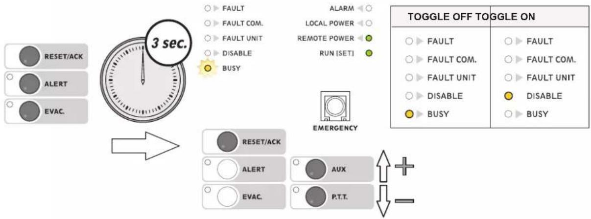
To set the P.T.T. key in the toggle mode, press the ALERT, EVAC and RESET/ACK keys simultaneously and hold them down for more than 3 seconds. When the RUN/SET LED stops flashing and remains steady ON, release the keys. On pressing the RESET/ACK key, the LEDs will show the current setting (default factory setting: toggle OFF). To change the status, hold the RESET/ACK key down and press AUX (to activate the toggle mode) or the P.T.T. key (to de-activate it). The LED's corresponding to the modes are shown in the following table.
flowchart
graph TD
    A["RESET/ACK"] --> B["3 sec."]
    C["ALERT"] --> B
    D["EVAC."] --> B
    B --> E["RESER/ACK"]
    E --> F["AUX"]
    F --> G["P.T.T."]
    H["FAULT"] --> I["LOCAL POWER"]
    J["FAULT COM."] --> K["REMOTE POWER"]
    L["FAULT UNIT"] --> M["RUN [SET"]]
    N["DISABLE"] --> O["BUSY"]
    P["ALARM"] --> Q["EMERGENCY"]
    R["TOGGLE OFF TOGGLE ON"]
    S["FAULT"] --> T["FAULT COM."]
    U["FAULT UNIT"] --> V["FAULT COM."]
    W["DISABLE"] --> X["DISABLE"]
    Y["BUSY"] --> Z["BUSY"]
To leave the settings mode and save the changes made, press the ALERT, EVAC and RESET/ACK keys again: the RUN/SET LED will start flashing again. If you do NOT want to save the changes made, simply wait for the timeout (about 10 seconds), after which the previous settings will be restored.
4.4 Microphone sensitivity
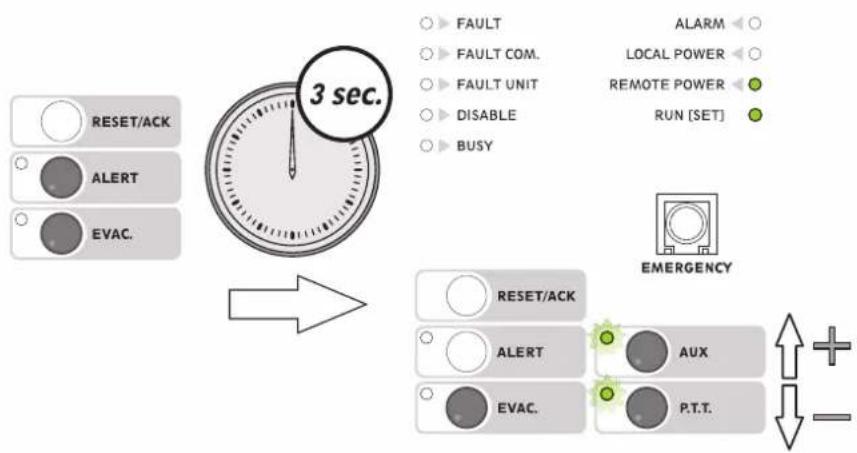
When the station is close to the speakers, it is possible that acoustic feedback may occur, resulting in a hissing noise from the loudspeakers (Larsen effect). To avoid this, it is necessary to lower the sensitivity of the microphone. To set the sensitivity of the microphone, press the ALERT and EVAC keys simultaneously and hold them down for more than 3 seconds. When the RUN/SET LED stops flashing and remains steady ON, release the keys. Holding the EVAC key down, press AUX to increase the sensitivity of the microphone or P.T.T. to decrease it.
flowchart
graph TD
    A["3 sec."] --> B["Arrow"]
    B --> C["RESET/ACK"]
    B --> D["ALERT"]
    B --> E["EVAC."]
    C --> F["FAULT"]
    D --> G["FAULT COM."]
    E --> H["FAULT UNIT"]
    F --> I["DISABLE"]
    G --> J["BUSY"]
    H --> K["REMOTE POWER"]
    I --> L["RUN [SET"]]
    J --> M["ALARM"]
    K --> N["LOCAL POWER"]
    L --> O["EMERGENCY"]
    M --> P["AUX"]
    N --> Q["P.T.T."]
    O --> R["+"]
    P --> S["-"]
The appropriate LEDs will flash to indicate that the adjustment is being made. Once the (minimum or maximum) limits have been reached, the LEDs will remain steady ON. To leave the settings mode and save the changes made, press the ALERT and EVAC keys again. If you do NOT want to save the changes made, simply wait for the timeout (about 10 seconds), after which the previous settings will be restored.
UK
SETTINGS
4.5 Output level
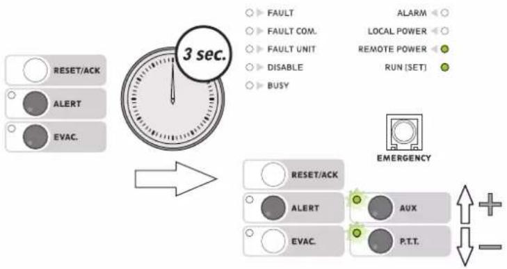
To set the output level, press the ALERT and EVAC keys simultaneously and hold them down for more than 3 seconds. When the RUN/SET LED stops flashing and remains steady ON, release the keys. Holding the ALERT key down, press AUX to increase the output level or P.T.T. to decrease it.
flowchart
graph TD
    A["3 sec."] --> B["WEIGHT"]
    B --> C["RESET/ACK"]
    B --> D["ALERT"]
    B --> E["EVAC."]
    C --> F["FAULT COM."]
    D --> G["FAULT UNIT"]
    E --> H["DISABLE"]
    E --> I["BUSY"]
    F --> J["ALARM"]
    G --> K["LOCAL POWER"]
    H --> L["REMOTE POWER"]
    I --> M["RUN [SET"]]
    N["EMERGENCY"] --> O["RESET/ACK"]
    N --> P["ALERT"]
    N --> Q["AUX"]
    N --> R["P.T.T."]
    O & P & Q & R --> S["+/-"]
The appropriate LEDs will flash to indicate that the adjustment is being made. Once the (minimum or maximum) limits have been reached, the LEDs will remain steady ON. To leave the settings mode and save the changes made, press the ALERT and EVAC keys again. If you do NOT want to save the changes made, simply wait for the timeout (about 10 seconds), after which the previous settings will be restored.
4.6 LOW-CUT filter
To set the LOW-CUT filter, press the ALERT and EVAC keys simultaneously and hold them down for more than 3 seconds. When the RUN/SET LED stops flashing and remains steady ON, release the keys.
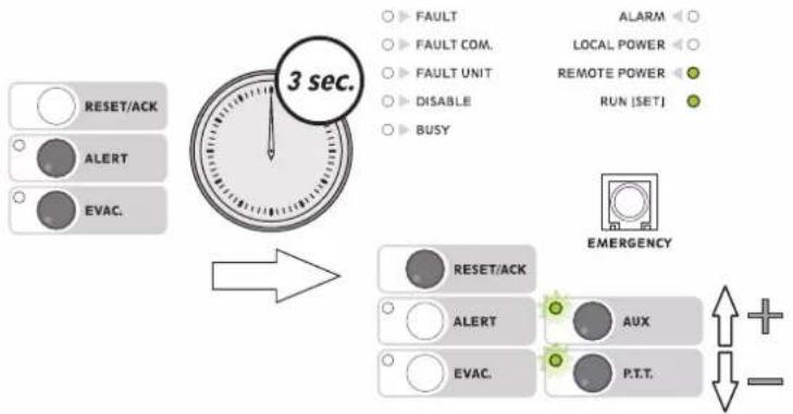
flowchart
graph TD
    A["3 sec."] --> B["RESET/ACK"]
    A --> C["ALERT"]
    A --> D["EVAC."]
    B --> E["FAULT"]
    C --> F["FAULT COM."]
    D --> G["FAULT UNIT"]
    E --> H["DISABLE"]
    F --> I["BUSY"]
    G --> J["REMOTE POWER"]
    H --> K["RUN (SET)"]
    I --> L["ALARM"]
    J --> M["LOCAL POWER"]
    K --> N["EMERGENCY"]
    L --> O["RESSET/ACK"]
    M --> P["AUX"]
    N --> Q["P.T.T."]
    O --> R["+"]
    P --> S["-"]
Press the RESET/ACK. key. The LEDs will indicate the current settings:
AUX LED ON = filter ON
P.T.T. LED ON = filter OFF
Holding the RESET/ACK key down, press AUX to activate the filter or P.T.T. to de-activate it.
To leave the settings mode and save the changes made, press the ALERT and EVAC keys again. The RUN/SET LED will start flashing again. If you do NOT want to save the changes made, simply wait for the timeout (about 10 seconds), after which the previous settings will be restored.
Note: To check the effects of the changes described under points 4.3 to 4.6 above, a normal call so as to listen to your own voice is recommended.
Note for INSTALLERS:
While installing and configuring the system, it may be necessary to mute the failure signalling buzzer temporarily. To do this, there is a switch (11) on the rear panel, which has to be positioned with a small screwdriver. Remember to re-activate the buzzer after completing the operations.
UK
TECHNICAL DATA
| FMD 2001 FMD 2012 | ||
| N° of zones selectable - 12 | ||
| Power supply voltage 24 Vdc | ||
| Maximum absorption @24Vdc 60 mA 130 mA | ||
| Typical output level 300 mV | ||
| Distortion < 1% | ||
| S/N ratio > 60 dB | ||
| S/N ratio (weighted “A”) > 65 dBA | ||
| Frequency response 130 ÷ 19.000 Hz | ||
| Low-Cut Filter -3 dB / 380 Hz | ||
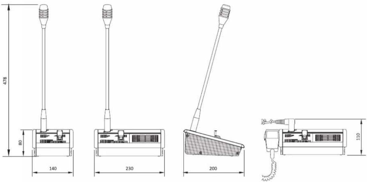
| Dimensions (W x H x D) 140 x 80 x 200 mm 230 x 80 x 200 mm | ||
| Net weight | 0,77 kg | 1,55 kg |
- Note -
FBT will not accept any liability for damage to property and/or persons arising out of incorrect use of the equipment or of procedures that do not comply with the instructions provided in this booklet. FBT strive to improve their products continuously, and therefore reserve the right to make changes to the drawings and technical specifications at any time and without notice.
D
Fireman Microphone Desktop
| FAULT | ALARM |
| FAULT COM. | LOCAL POWER |
| FAULT UNIT | REMOTE POWER |
| DISABLE | RUN [SET] |
| BUSY |
Abb. 3.1.1

![Fireman Microphone Desktop FAULT FAULT COM. FAULT UNIT DISABLE BUSY ALARM LOCAL POWER REMOTE POWER RUN [SET] FBT EMERGENCY RESET/ACK ALERT AVIC. P.T.T. FMD 2001](/content/2026/05/896340/images/2e92a0b180f95ba8e4e5ab5159474b8ef07bfa87a93cb7af65c671adc1ce4e71.jpg)
Abb. 3.2.1 Abb. 3.2.2
All information included in this operating manual have been scrupulously controlled; however FBT is not responsible for eventual mistakes. FBT Elettronica S.p.A. has the right to amend products and specifications without notice.
- Chiamate broadcast
- Numbered references
- UK
- CONNECTIONS
- N.B.!
- Sizing
- USE
- Various different types of use can be identified:
- Manual emergency activation
- Sending live emergency messages
- Sending pre-recorded emergency messages
- Broadcast calls
- Note
- Zone selection (FMD 2012 only)
- • to send selective live messages
- • to send selective pre-recorded messages
- LED steady ON = EVAC
- • to send selective messages in the broadcast mode
- AUX function
- RESET/ACK function
- Message RESET (RESET function)
- Resetting the failure acknowledgement buzzer (ACK function)
- SETTINGS
- Address
- Priority
- Note:
- P.T.T. Toggle
- Microphone sensitivity
- Output level
- LOW-CUT filter
- Note for INSTALLERS:
- TECHNICAL DATA
- - Note -
- D
Brand : FBT
Model : FMD 2001
Category : Loudspeaker