
V4 U - Microphone Schoeps - Free user manual and instructions
Find the device manual for free V4 U Schoeps in PDF.


| Product Type | Studio Vocal Microphone |
| Brand | Schoeps |
| Model | V4 U |
| Polar Pattern | Cardioid |
| Transducer Type | Classical condenser transducer with external polarization |
| Frequency Range | 50 Hz - 22 kHz |
| Sensitivity | 16 mV/Pa |
| Equivalent Noise Level | 15 dB (A-weighted), 25 dB (CCIR-weighted) |
| Signal-to-Noise Ratio | 79 dB-A |
| Maximum SPL | 144 dB SPL at 0.5% THD |
| Maximum Output Voltage | 4.8 V |
| Low-Cut Filter | 40 Hz (non-switchable, third-order) |
| Powering | 48 V phantom power (P48) |
| Current Consumption | 3.3 mA |
| Output Impedance | 50 Ohms (10 Hz - 30 kHz) |
| Minimum Load Impedance | 600 Ohms |
| Dimensions | Length 194 mm, diameter 34 mm, capsule head width 45 mm |
| Weight | 302 g |
| Surface Finish | Lacquered |
| Head Swivel Range | ±20° |
| Color Options | Blue or gray |
| Included Accessories | Rugged wooden case, owner's manual |
| Optional Accessories | SGV stand clamp, USM-V4 elastic suspension, K EMC 10U cable |
| Warranty | 24 months |
| Care | Clean with soft moist cloth; avoid solvents; store in closed container |
Frequently Asked Questions - V4 U Schoeps
User questions about V4 U Schoeps
0 question about this device. Answer the ones you know or ask your own.
Ask a new question about this device
Download the instructions for your Microphone in PDF format for free! Find your manual V4 U - Schoeps and take your electronic device back in hand. On this page are published all the documents necessary for the use of your device. V4 U by Schoeps.
USER MANUAL V4 U Schoeps
natural_image
Close-up of a metallic microphone with a neck-mounted head and attached shaft, against a solid maroon background (no text or symbols visible)SCHOEPS
Mikrofone

V4 U
Studio Vocal Microphone
Inhaltsverzeichnis
Seite
Charakteristika 2
Table of Contents page
General Description 9
Applications for the V4 U/Startup 10
Phantom Powering 11
Avoiding Interference 12
Care and Maintenance 13
Specifications 14
Warranty / Declaration of Conformity 15
Bedienungsanleitung
User Guide
natural_image
Open wooden box containing a mechanical tool and a circular object, no visible text or symbolsnatural_image
Three industrial sensors labeled SGV, USM-V4, and K EMC 10U, shown with no visible text or symbols on the devices themselves.Congratulations on your purchase of the SCHOEPS V4 U studio vocal microphone.
To get the most out of your microphone, there are a few basic principles to consider. This guide covers these principles, followed by some notes on maintenance and care. Specifications are provided in the appendix.
General Description
The V4 U is a classic condenser microphone with a cardioid pattern. It offers a small-diaphragm capsule with a 33 mm diameter beveled collar which controls the polar response, creating a sonic character like that of a large-diaphragm capsule.
The V4 U stands out:
– for its warm, clear sonic character, with smoothly rolled-off diffuse-field response
- for its capsule head with adjustable tilt angle
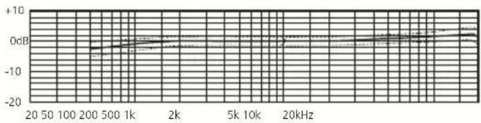
– for its optimal on-axis frequency response, featuring a mild high-frequency lift
– for its very smooth polar response, with carefully controlled narrowing of the pattern at high frequencies
– for its diffuse-field response, featuring a gentle roll-off at high frequencies
– for its newly-designed circuitry, which handles very high sound pressure levels without attenuation
natural_image
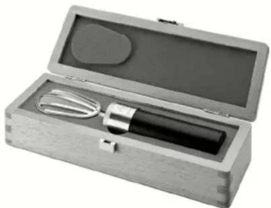
Open wooden box containing a mechanical tool and a circular object, no visible text or symbolsIncluded accessories:
- rugged wooden case
- owner's manual
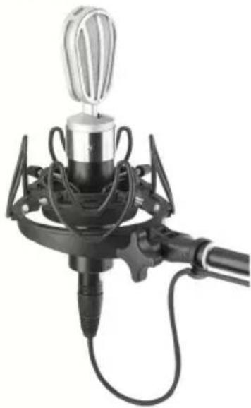
Optional accessories:
- SGV stand clamp
- USM-V4 elastic suspension
- microphone cable, e.g. K EMC 10U (10 m, with RF-protected XLR-3 connectors)
SGV

natural_image
Close-up of a handheld industrial sensor or probe with a metallic head and black cable, no visible text or symbols.USM-V4
natural_image
Close-up of a black-and-white photo of a microphone device with a metallic top and attached tubing (no visible text or symbols)
natural_image
Coiled black cable with two connectors (no text or symbols visible)K EMC 10U
Applications for the V4 U
The V4 U is the ideal microphone for vocal and instrumental solo work in recording and broadcast studios. It offers the typical SCHOEPS sound quality, with warmth and fidelity to detail.
It is extremely resistant to overload, since its amplifier circuitry can handle very high sound pressure levels (up to 144 dB SPL) without distortion. That is a far higher level than occurs at the bell of a trumpet, for example (ca. 130 dB SPL).
The capsule head features a sturdy yet elegant swivel joint which allows the capsule to be tilted. Thus the microphone can remain vertically oriented even when the sound source is above or below the capsule.
Pop Screening
The V4 U has a two-layer screen built in. The coarser layer offers protection from accidental damage, while the finer layer guards the transducer from plosives and air movement.
For very close placement, a conventional popscreen should also be used.
Capsule Swivel
The microphone capsule can be tilted ±20^ by means of a swivel joint, which does not require (or permit) any lubrication.
Filters
When designing the V4 U, SCHOEPS consciously chose to omit any switchable filters or attenuators. The microphone's very high maximum SPL makes it practically overload-proof. But low-frequency disturbances, due to plosive sounds or handling noise for example, could produce disproportionately large signal amplitudes at the output. For this reason the V4 U has a third-order filter which effectively suppresses noise below 40 Hz.
From a technical point of view, the V4 U is
built as a combination of two main components: a transducer (capsule) and a microphone amplifier.
The capsule is the component that converts sound into a varying electrical voltage. It also determines the polar pattern and, for the most part, the sound quality of the microphone.
The amplifier of the V4 U generates the voltage needed to polarize (charge) the capacitive capsule. Its audio circuitry only amplifies the current, making the signal low-impedance so that it can be sent through a cable. The output is electrically balanced in order to eliminate electromagnetic interference in the cable. This also prevents "AC hum," for example. The V4 U has a transformerless output stage without coupling capacitors, which allows both the output impedance and the distortion to be kept very low. Special RFI filtering prevents any radio frequency energy picked up via the cable (e.g. from mobile phones) from entering the microphone's output circuitry.
Startup
The amplifier of the V4 U is electrically active and requires operating current. This will most often be supplied by the inputs of a mixer, preamplifier or recorder with suitable microphone powering built in.
Like most modern, solid-state professional microphones, the V4 U uses a standardized powering scheme known as "phantom powering." Most recording equipment offers a 48-Volt supply for such microphones.
Please note: Our microphones are developed for, and tested with, power supplies that conform to the requirements of this standard. Proper operation with non-standard power supplies cannot be guaranteed. Circuit arrangements that deviate from the standard can cause operational problems (i.e. distortion or partial loss of signal), particularly at high sound pressure levels.
PhantomPoweringtoStandard DIN EN 61938
"Phantom" powering is the standard way to power studio condenser microphones via two-conductor, shielded cables. Both conductors are at the same DC voltage, and exactly the same supply current flows through both of them. Fig. 1 shows the only valid 48 V phantom powering circuit (abbreviation: P48) that can be built using resistors as opposed to a center-tapped input transformer. This illustration is based on the international standard document EN 61938.
The permissible tolerance of the feed resistor values as such is ±20% . However, the difference between the resistors of any one pair should be less than 0.4% (i.e. 27 Ohms). This close matching is necessary to maintain adequate impedance balance, which in turn is required for the sake of common mode rejection. It also avoids the flow of DC in an input transformer (should one be present), which could lead to distortion or reduced dynamic range.
A microphone designed for 48 V phantom powering may draw as much as 10 mA according to the standard. The SCHOEPS V4 U will draw only about 3.3 mA, well within this limit.
Although there is nothing particularly complicated or demanding about phantom powering, there are some power supplies, preamplifiers, and mixing desks which fail to meet this standard, and hence may not be able to power SCHOEPS microphones (or other modern, transformerless studio condenser microphones) adequately. If in doubt, equipment should be checked to verify its suitability for professional work with SCHOEPS microphones. A quick and easy way to check a phantom supply is described on page 15.
Unbalanced Operation
You may encounter a situation in which there is no balanced microphone input with phantom power available, but only an unbalanced microphone input – most likely without standard phantom powering, or perhaps with a different microphone powering scheme.
We strongly advise against connecting the V4 U directly to such inputs; the microphone is not designed for such operation, and the advantages of phantom powering (noise and interference rejection) will be completely lost. Instead, a high-quality microphone input transformer could be used to turn the unbalanced input into a balanced one, and then phantom powering can be supplied. This will allow the signal leads from the microphone to be kept balanced for best rejection of interference.
In this case one side of the transformer's output should be connected to ground, and if the unbalanced input has DC powering, the other lead from the transformer's output should be connected via a capacitor, to prevent DC from flowing through the transformer's secondary winding.
Fig. 1
Input with transformer
(or balanced, ungrounded
transformerless input)

* Tolerance: ±20%, however, the difference between the resistors of any one pair should be less than 0.4% (i.e. 27 Ohms)
Simultaneous Connection to Multiple Inputs
If a microphone has to be connected to multiple inputs simultaneously, an active microphone splitter should be used in order to preserve the loading and powering conditions for the microphone, as well as to prevent interference. In no event may the outputs of several microphones be connected in parallel to a single input.
Maximum CableLength
In the typical application of a studio vocal microphone, cables of just a few meters are used. The V4 U can be connected to cables up to 300 m in length. The practical limit depends on the electrical capacitance of the cable, which is sometimes an unknown quantity. The lower this capacitance is per unit length, the longer the cable can be. All SCHOEPS cables have very low capacitance (100 pF/m between the conductors).
The main risks with excessively long microphone cables are gradual losses at high frequencies due to the cable capacitance, some reduction in the ability to handle very high sound pressure levels, and increased pickup of interference.
Notes on Electromagnetic Compatibility
The SCHOEPS V4 U microphone is virtually immune to magnetic, electric and electromagnetic fields.
Due to the wide dynamic range of studio microphones, the smallest signal amplitudes are in the microvolt range (1/1,000,000 Volt). A microphone can therefore never be expected to be immune to all possible disturbances in all circumstances, but the following suggestions can help to reduce any noise induction:
1) Keep both the microphone and the cable away from known sources of interference such as monitors, digital equipment (computers), RF emitters (mobile phones and other personal communication devices that emit radio frequency energy), power transformers, power lines, SCR dimmers, switching power supplies, etc.
2) Use only high-quality cables with a high degree of shield coverage and low shield resistance, e.g. SCHOEPS K EMC 5U.
3) Keep all cables as short as possible.
4) Dress audio cables away from power cables. If they must cross, it should be at right angles
5) At the preamp or mixer input, the shield of the microphone cable should connect to the chassis ground in the shortest, lowest-impedance way possible. This coupling can be capacitive rather than galvanic; see AES standard AES48-2005.
Vibration
If noise from mechanical vibration is likely to reach a stand- or boom-mounted microphone, a shock mount (elastic suspension, e.g. SCHOEPS USM V4) should be used, and a loop of slack cable isolated and clamped or tied off so that it does not become another way for vibrations to reach the microphone. When properly set up, the cable should not "pull" on the microphone.
Overload
... practically never happens with the V4 U, because of its very high maximum SPL. Only strong air currents (e.g. from plosive consonants very close to the microphone) can cause very high signal amplitudes and possible overload.
The input circuitry of a mixer, preamp or recorder can be overloaded even when the microphone itself is not. This is true particularly with consumer audio equipment, though even today some professional equipment is still designed primarily for use with dynamic microphones or with earlier, less sensitive condenser microphones. If an input sensitivity control is available, it should be set low enough to avoid input overload, but not so low as to cause excess noise (though a few dB of hiss is generally preferable to hard clipping). Level meters and overload indicators may not detect input overload even in fully professional equipment; often they operate only at later stages of the circuitry.
If overload occurs when microphone powering, high sound pressure levels and air currents are not the problem, and an input sensitivity
control cannot be turned down, the next logical step is to plug in a balanced resistive "pad" (attenuator) such as the SCHOEPS MDZ 10 or MDZ 20 at the preamp input. If the sound quality improves, leave the pad in place. With respect to RF interference it is always better to pad the preamp input than the microphone; this is part of why the V4 U has no such pad.

resistive attenuator
MDZ 10
Low-frequency disturbances may not be directly audible as such, but infrasonic noise can still cause overload in some stage of the signal chain. To avoid this, the V4 U has a non-switchable active filter that suppresses any noise below 40 Hz.
If there is a risk of motion being transmitted through floorboards, etc., the use of an elastic suspension is recommended.
Any other overload for which there seems to be no sensible explanation may actually be a symptom of incorrect or inadequate microphone powering. Powering systems and their requirements are discussed near the beginning of this User Guide on page 11.
Care and Maintenance
Use only a soft, slightly moist cloth to clean the exterior of the V4 U; never use solvents or cleaning fluids, which can attack the surface finish of the microphone.
Prevent any kind of liquid from getting into the microphone, since that can lead to damage and loss of functionality.
Because of the acoustically open design of the capsule head, among other reasons, avoid using the V4 U in dirty or dusty environments, which can affect the functioning of the microphone. Especially in combination with humidity, this can lead to popping and crackling noises
(often described as "frying sounds").
After use, particularly if the microphone will be sitting unused for some length of time, it should be stored in a closed container such as the supplied wooden case.
If the microphone should require cleaning in the area around the swivel joint, we recommend using a soft brush or a miniature vacuum cleaner. Do not use compressed air or propellant of any kind, since that could force dirt into the mechanism.
We definitely advise against opening the microphone. The swivel joint is designed to work maintenance-free for many years, but if problems should somehow arise, please send the microphone to the factory for adjustment.
What to do if...
the microphone is noisy (clicks and pops) in high humidity?
If the microphone is brought in from the cold outdoors to a warm (and especially humid) environment, snapping or clicking noises can result from the condensation of moisture. In this event the microphone should be given 30 to 60 minutes to warm up, and will then generally perform flawlessly.
If this treatment does not eliminate the noise, it is possible that dirt has gotten inside the transducer (capsule) itself – in which case the microphone must be sent back to the factory for cleaning. We strongly advise customers not to open the microphone or attempt to clean it themselves. Doing so would also invalidate all warranties.
Polar pattern: . . . . . . . . . . . . . . cardioid
Transducer type ..... classical condenser transducer with external polarization
Frequency range: 50 Hz - 22 kHz
Sensitivity: 16 mV/Pa
Equivalent noise level: ..... 15 dB (A-weighted)*, 25 dB (CCIR-weighted)*
Signal-to-noise ratio (A-weighted): 79 dB-A
Maximum SPL: 144 dB SPL at 0.5% THD
Maximum output voltage: ..... 4.8 V
Low-cut filter: 40 Hz
Powering: 48 V phantom
Current consumption: ..... 3.3 mA
Output impedance: ..... 50 Ohms (10 Hz - 30 kHz)
Minimum load impedance: .... 600 Ohms
Length: 194 mm (24.4")
Diameter of cylinder: 34 mm (1.34")
Width capsule head: 45 mm (1.77")
Weight: 302 g (10.65 ounces)
Surface: lacquered
Head swivel degree span: .....+/- 20°
Standard color options: ..... blue or gray * according to IEC 60268-1
line
| Frequency | Value | | --------- | ----- | | 20 | -5 | | 50 | -3 | | 100 | -2 | | 200 | -1 | | 500 | 0 | | 1k | 1 | | 2k | 2 | | 5k | 3 | | 10k | 4 | | 20kHz | 5 |Frequency response (tolerances shown)

radar
| Frequency (Hz) | Value (dB) | | -------------- | ---------- | | 0 | 0 | | 90 | -10 | | 180 | -30 | | 270 | -10 |Polar diagram
Warranty
We guarantee our products for a period of twenty-four months. The warranty period begins on the date of purchase.
Please provide your bill of sale in all cases as proof of warranty; without it, repairs will be undertaken only at the owner's expense.
We reserve the right to satisfy all warranty requirements regarding defects of workmanship or materials by means of repair or partial or complete replacement of the product, at our sole discretion.
Excluded from this warranty are defects due to misuse (e.g. incorrect operation; mechanical damage), abuse or "acts of God". This warranty becomes void in the event of tampering by unauthorized persons or agencies.
To secure your rights under this warranty, send the product with proof of purchase and a precise description of the malfunction, at your expense, either to SCHOEPS (if you are a customer in Germany), or to our representative (if you are a customer outside Germany).
Prior to sending your defective product for repair, please contact your local dealer or distributor for instructions. In exceptional cases you can, by prior arrangement with SCHOEPS, send the product directly to us from a foreign country.
This warranty does not affect any contractual agreements which may exist between the buyer and seller of the equipment.
This warranty is world-wide.
Declaration of Conformity
The CE-mark guarantees that all products conform to relevant standards approved by the European Community. The products described in this User Guide comply with current, relevant standards when used with cables from SCH0EPS.
Relevant directives:
EMC Directive: 2004/108/EC
Relevant standards:
EN 55 103-1, -2 and those referred to by them.
Verifying correct 48 V phantom powering
These measurements should be made at an unused input. Reduce the channel gain to the minimum to protect loudspeakers, etc. If microphones are connected to other inputs at the same time, no substantial difference should occur in the results.
There are three methods:
Method 1
Measure the open-circuit voltage between ground (pin 1) and either pin 2 or pin 3 of the XLR input. Given the permitted tolerances, this voltage should be between 44 and 52 VDC for P48. Then, measure the short-circuit current between ground (pin 1) and either pin 2 or pin 3 of the XLR input. Given the permitted tolerances, this current should be between 5.9 and 8.5 mA DC for P48.
Note: Well-designed phantom power supplies must tolerate at least a temporary short circuit without damage; an unbalanced connection (which is occasionally necessary) would cause the same current to be drawn. To be safe, however, do not leave the short circuit in place any longer than necessary.
Method 2
Measure the DC voltages on the modulation leads with a microphone connected, e.g. by opening the connector shell of the cable. The two voltages (from pin 2 and pin 3 to pin 1) must be identical. They should fall in the range from 33.5 Volts to 40 Volts.
Method 3
Use a SCHOEPS PHS 48 tester. Plug it in; if the LED glows and stays lit, all is well.
Änderungen und Irrtümer vorbehalten. Not responsible for errors or omissions. Subject to change without notice.
140101
SCHOEPSGmbH
Spitalstr. 20
D-76227 Karlsruhe (Durlach)
Germany
Tel: +49 (0)721 943 20-0
Fax: +49 (0)721 943 2050
www.schoeps.de
mailbox@schoeps.de
Schall
Technik

CE


- SCHOEPS
- Mikrofone
- V4 U
- Studio Vocal Microphone
- Inhaltsverzeichnis
- Table of Contents page
- Bedienungsanleitung
- User Guide
- General Description
- Applications for the V4 U
- Pop Screening
- Capsule Swivel
- Filters
- Startup
- PhantomPoweringtoStandard DIN EN 61938
- Unbalanced Operation
- Simultaneous Connection to Multiple Inputs
- Maximum CableLength
- Notes on Electromagnetic Compatibility
- Vibration
- Overload
- Care and Maintenance
- Warranty
- Declaration of Conformity
- Verifying correct 48 V phantom powering
- Method 1
- Method 2
- Method 3
Brand : Schoeps
Model : V4 U
Category : Microphone