B 40 L EC F - Cooker SCHOLTES - Free user manual and instructions
Find the device manual for free B 40 L EC F SCHOLTES in PDF.
User questions about B 40 L EC F SCHOLTES
0 question about this device. Answer the ones you know or ask your own.
Ask a new question about this device
Download the instructions for your Cooker in PDF format for free! Find your manual B 40 L EC F - SCHOLTES and take your electronic device back in hand. On this page are published all the documents necessary for the use of your device. B 40 L EC F by SCHOLTES.
USER MANUAL B 40 L EC F SCHOLTES
Electrical connection
Gas connection
Data plate
Burner and nozzle specifications
Description of the appliance, 24
Overall view
Start-up and use, 25-27
Practical advice on using the burners
Precautions and tips, 28
General safety
Disposal
Maintenance and care, 29
Switching the appliance off
Cleaning the appliance
Gas tap maintenance
Troubleshooting, 30
! Before operating your new appliance please read this instruction booklet carefully. It contains important information concerning the safe operation, installation and maintenance of the appliance.
! Please keep these operating instructions for future reference. This manual contains important information relating to appliance installation, operation and safety.
Positioning
! Keep packaging material out of the reach of children. It can become a choking or suffocation hazard. (see Precautions and tips).
! The appliance must be installed by a qualified professional in compliance with the instructions provided. Incorrect installation may cause harm to people and animals or may damage property.
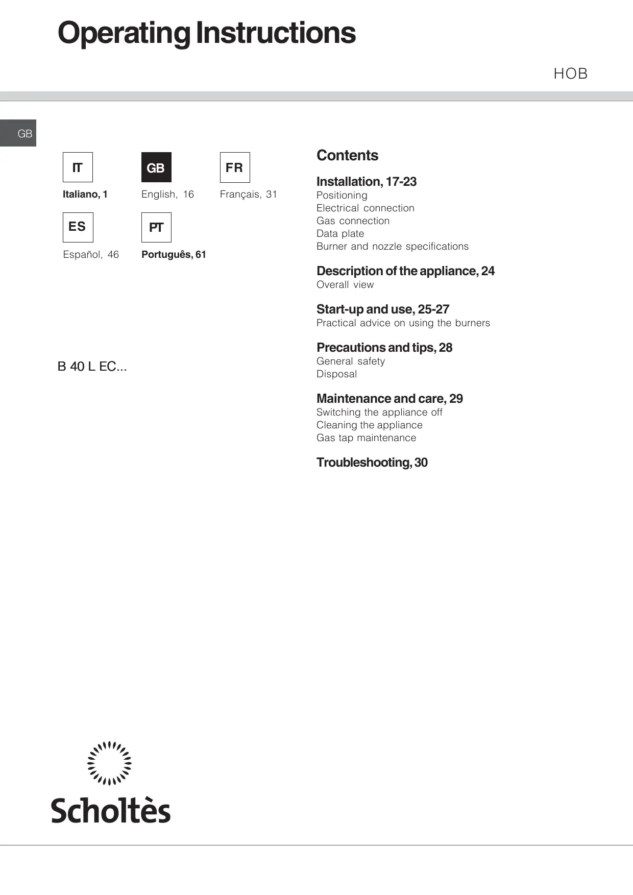
! This unit may be installed and used only in permanently ventilated rooms in accordance with British Standard Codes Of Practice: B.S. 6172 / B.S. 5440, Par. 2 and B.S. 6891 Current Editions. The following requirements must be observed:
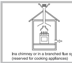
The following requirements must be observed:
- The room must be fitted with an air extraction system which expels any combustion fumes. This may consist of a cooker hood or an electric fan which starts automatically every time the appliance is switched on.
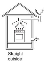
- The room must also allow proper air circulation, as air is needed for combustion to occur normally. The air flow must not be less than 2m^3/h per kW of installed power.
The air circulation system may take air directly from the outside environment by means of a pipe with an inner cross section of at least 100~cm^2 ; the opening must not be vulnerable to any type of blockages.
The system can also provide the air needed for combustion indirectly, i.e. from adjacent
rooms fitted with air circulation ducting as described above. However, these rooms must not be communal rooms, bedrooms or rooms which may present a fire hazard.
- Liquid petroleum gas sinks to the floor as it is heavier than air. Therefore, rooms containing LPG cylinders must also be equipped with vents to allow gas to escape in the event of a leak. As a result LPG cylinders, whether partially or completely full, must not be installed or stored in rooms or storage areas which are below ground level (cellars, etc.). It is advisable to keep only the cylinder currently being used in the room, positioned so that it is not subject to heat produced by external sources (ovens, fireplaces, stoves, etc.) which could raise the temperature of the cylinder above 50^ .
Built-in appliance
Gas and mixed hobs are manufactured with type X degree protection against overheating. The following precautions must be taken when installing the hob:
- Kitchen cabinets which are adjacent to the appliance and taller than the top of the hob must be at least 140
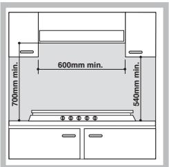
mm from the edge of the hob.
- Cooker hoods must be installed in accordance with their relative installation instruction manuals and at a minimum distance of 700 mm from the hob.
- Place wall cabinets which
are adjacent to the cooker hood at a minimum height of 540mm from the hob (see figure).
If the hob is installed beneath a wall cabinet, the latter must be situated at a minimum of 700 mm above the hob.
Installation
Make sure you take all the necessary precautions to guarantee proper installation in compliance with the applicable norms in force regarding accident-prevention for electrical connection. For the correct operation of the appliance when built into the cabinet, it is vital that the minimum distances illustrated in Fig. 1 be respected. The hob features a type Y degree of protection against overheating in compliance with norms. All surfaces adjacent to the cabinet and the back panel should be made of materials resistant to a temperature of 65^ .
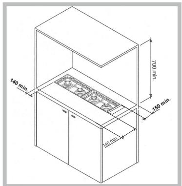
Fig. 1
Securing the appliance to the cabinet
There are three different groups of appliance as far as installation is concerned:
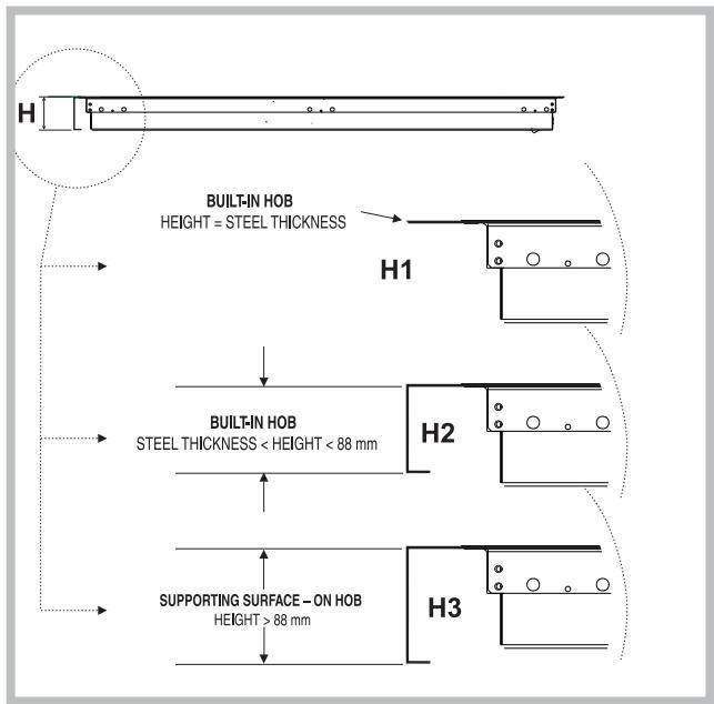
Fig. 2
1- Built-in hobs to be slotted in (Class 3 - see figure 2, detail H1). In this case it is necessary to make a hole in the worktop whose measurements match those of the hob. The measurement at the side should be reduced by 10mm for horizontal sides and 6mm for vertical sides, in order to ensure that 10mm of the hob perimeter overlaps with and rests on top of the supporting surface for horizontal sides (this figure should be 6mm for vertical sides, see figure 4a-4b). To slot in the hob flush with the worktop, the cut-out on this supporting surface must be lowered, so that both the edge of the hob and the seal under it can be positioned there.
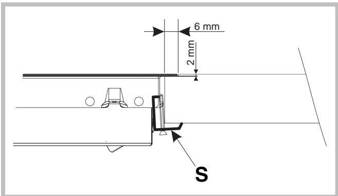
Fig. 3
Before fitting the hob to the worktop, position the seal provided along the perimeter of the hob, as illustrated in Fig. 5. Brackets for fixing worktops to the cabinet have been provided, and these should be fitted as shown in detail (Fig. 3).
2-Built-in hobs (Class 3) with edges lower than 88 mm (see figure 2, detail H2); to install this type of hob, a hole large enough to accommodate the whole lower casing of the appliance must be made on the worktop intended to be under the hob. Remember to leave a gap of at least 1cm between the lower casing and the worktop around the whole perimeter of the appliance (the underside of the casing can, however, touch the surface below it). To fit the appliances, follow the instructions given above in point 1 or use any supplementary instruction leaflet that is provided in special cases.
3- Sit-on hobs (Class 1) with edges higher than 88 mm (see figure 2, detail H3). In this case, the lower casing of the hob does not protrude further than the edge of the appliance. Even when the hob is resting on the worktop, it will suffice to leave space for the gas supply tube and electricity supply cable.
N.B.: If the appliance is installed above an oven, a wooden panel must be fitted underneath the hob as insulation. It should be fixed at least 20mm away from the hob casing.
The appliance must be fitted to the kitchen cabinets using suitable fixing accessories (these are provided) which may vary according to the type of installation required and the proportions of the appliance.
Built-in appliance B 40 L EC F
Fig. 4a
Built-In appliance B 40 L EC.1 SF
Fig. 4b
Fig. 5
Electrical connection
THE EQUIPMENT MUST BE EARTHED CORRECTLY.
The hobs are designed for operation with an alternating current at the power supply voltage and frequency indicated on the data plate (this is located underneath the hob; alternatively the information may be found at the end of the instruction manual). Make sure that the local power supply voltage value is the same as the value indicated on the data plate.
Connecting the power supply cable to the mains.
If direct connection to the electricity mains supply is required, an omnipolar switch with a minimum contact opening of 3mm must be installed between the appliance and the mains. The switch must be suitable for the charge indicated and must comply with current electrical regulations.
The yellow-green wire must not be interrupted by the switch.
The supply cable must not be placed in areas where it could reach temperatures higher than 50^ .
If the appliance is to be installed above a built-in electric oven, the electrical connection of the hob and the oven must be performed separately, both for electrical safety purposes and to make extracting the oven easier.
Do not use reduction devices, adaptors or shunt devices, as these may cause overheating or burning. Before connecting the appliance to the power supply, make sure that:
- The modulating valve and the electricity supply can withstand the maximum power of the appliance (see the data plate for details);
- The supply system is earthed correctly, in compliance with current laws and regulations;
- The power socket or omnipolar switch may be reached easily once the hob has been installed.
WE HEREBY DECLINE ALL LIABILITY WHEREV ACCIDENT PREVENTION LEGISLATION HAS NOT BEEN OBSERVED.
Replacing the cable
! The cable must be checked regularly and replaced by authorised technicians only.
Use a H05RR-F rubber cable (or H05VV-F cable for non-/CS models) with a cross-section of 3 × 0.75 mm^2 . The yellow-green wire should be 2 or 3 cm longer than the other wires.
Gas connection
- Check that the appliance is set for the type of gas available and then connect it to the mains gas piping or the gas cylinder in compliance with current regulations and standards.
- This appliance is designed and set to work with the gas indicated on the label situated on the actual hob. If the gas supply is other than the type for which the appliance has been set, proceed with replacing the corresponding nozzles (provided), following instructions given in the paragraph "Adaptation to different types of gas".
- For trouble-free operation, suitable use of energy and longer life of the appliance, make sure that the supply pressure complies with the values indicated in the table 1 "burners and nozzles specifications, otherwise install a special pressure regulator on the supply pipe in compliance with current standards and regulations.
- Connect in such a way that the appliance is subjected to no strain whatsoever.
Either a rigid metal pipe with fittings in compliance with the standards in force must be used for connecting to the nipple union (threaded 12 G male fitting) situated at the rear of the appliance to the right (Fig.6), or flexible steel pipe in compliance with the standards in force, which must not exceed 2000 mm in length.
Should it be necessary to turn the fitting, the gasket (supplied with the appliance) must be replaced. Upon completion of installation, check the gas circuit, the internal connections and the taps for leaks using a soapy solution (never a flame). Also check that the connecting pipe cannot come into contact with moving parts which could damage or crush it. Make sure that the natural gas pipe is adequate for a sufficient supply to the appliance when all the burners are lit
Important: A pressure regulator, in compliance with the standards in force, must be inserted when connecting to a liquid gas supply (in a cylinder).
Adapting to different types of gas
To adapt the hob to a different type of gas other than the default type (indicated by the label placed on the upper part of the hob or on the packaging), the burner nozzles should be replaced as follows:
- remove the hob grids and slide the burners off their seats;
- unscrew the nozzles (fig. 7) using a 7 mm socket spanner, and replace them with nozzles for the new type of gas (see table 1 "Burner and nozzle characteristics").
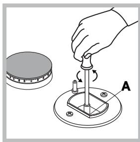
Fig. 7
After replacing the nozzles, change the hob setting using the control panel as follows:
While the hob is switched off, press the power button T1.
Press the lock button T2 (D1 lights up).
Press the buttons T2, T7 and T11 simultaneously, holding them down until a numerical value appears on the display D2.
At this point, with the hob set to methane G20 20 mbar, the display shows 01; to convert the hob to operation with G30 29 mbar, press the T4 button once, so that the value 02 appears on the display D2. The hob will allow 2 adjustments to be made: 01 and 02, which correspond to G20 20 mbar and G30 29 mbar respectively. To save the new setting, press the buttons T2, T7 and T11 simultaneously (hold them down for a few seconds, until you exit the function - approximately 5 seconds); the hob will appear to be switched off with the keypad locked. Press the unlock button T2 to operate the hob.
NOTE: if, during the gas conversion procedure, no buttons are pressed for a period of longer than 1 minute, the appliance automatically exits the function without saving the new setting.
Once this procedure is complete, replace the old rating sticker with one indicating the new type of gas used. Stickers are available in nozzle kits or can be obtained from any of our Technical Assistance Centres.
Setting the burners to minimum (only for gasG20) While the hob is switched off, press the power button T1. Press the lock button T2 (D1 lights up).
Press the buttons T2, T5 and T9 simultaneously and hold them down until the numerical value 01 appears on the display 02; on the displays D3, 4, 5 and 6 a numerical value appears which indicates the set minimum level. This level ranges from 9. (the point corresponds to a negative indication, i.e. -9) to 9: there are therefore 19 minimum levels to choose from. Press the + or - button corresponding to the burner you are adjusting; the burner will be activated at its maximum level to begin with, and will then be adjusted to the minimum setting value indicated at that moment by the display corresponding to that burner. Use the + or - buttons corresponding to the relevant burner to increase or decrease the minimum level; if the minimum level is too low, causing the burner to switch off or operate at such a low level that the thermocouple does not detect the flame, the burner operates at its maximum level for a few seconds and then returns to the minimum level. Repeat the process until the minimum level is high enough. To save the minimum level setting for the burner, as soon as it has been adjusted press the corresponding + and - buttons simultaneously; if this procedure is not performed the new setting will not be saved. Once the adjustment procedures have been completed for the various burners, press the T2, T5 and T9 buttons simultaneously (in this case the T2 button should be pressed slightly before the other two); hold the buttons down for approximately 5 seconds, until the hob returns to the status of being
switched off with the keypad locked.
To use the hob, unlock the keypad by pressing button T2.
NOTE: if none of the buttons on the keypad are pressed for more than 1 minute during the adjustment stage, the appliance exits the function automatically.
SAFETY TIMES FOR EACH BURNER:
The safety time when the appliance is switched off (the interval between the flame being switched off and subsequent P.C.B. reaction, namely re-ignition) is less than 10 seconds.
The safety time (the interval between the opening of the valve and its closure if no flame is detected; this coincides with the maximum spark duration) is 6 seconds.
BREAKDOWN SITUATIONS AND RESULTING BEHAVIOUR OF THE APPLIANCE:
1 - Flame monitoring device breakage: the burner cannot remain lit and therefore enters its safety mode. A fault signal is shown on the display.
2 - No sparks: it is not possible to light the burner. The P.C.B. blocks the gas supply to the burner after the safety time has elapsed.
3 - Tap seizes up in any of the operating positions: the burner loses its ability to modulate the flame but can still be switched off and left in safe mode.
4 - The magnet seizes up in an open position: it is, nevertheless, possible to switch the appliance off.
5 - The magnet seizes up in a closed position: it is not possible to light the burner.
6 - Any breakdown of the P.C.B. will mean that it is not possible to operate the appliance at all.
| DATA PLATE | |
| Electrical connections | voltage of 230V ~ 50Hz (see data plate) |
| CE | This appliance conforms to the following European Economic Community directives: -2006/95/EEC dated 12/12/2006 (Low Voltage) and subsequent amendments - 2004/108/EEC dated 15/12/04 (Electromagnetic Compatibility) and subsequent amendments - 93/68/EEC dated 22/07/93 and subsequent amendments. - 2209/142/EEC dated 30/11/09 (Gas) and subsequent amendments. - 2002/96/EC and subsequent amendments. |
Burner and nozzle specifications
| Table 1 | Liquid gas | Natural gas | |||||||||
| BURNER | Diameter (mm) | Thermal power kW (H.s.*) | By-pass 1/100 G20 Reduc. G30/G31 | Injector 1/100 mm | Flow* g/h | Injector 1/100 mm | Flow* l/h G20 | ||||
| Nomin. | Reduc. G20 | Reduc. G30/G31 | G30 | G31 | |||||||
| C.Rapid | 100 | 3.00 | 0.7 | 0.7 | 39 | 86 | 218 | 214 | 116 | 286 | |
| B. Semi-rapid | 75 | 1.65 | 0.4 | 0.5 | 29 | 64 | 120 | 118 | 96 | 157 | |
| A. Auxiliary | 55 | 1.00 | 0.4 | 0.4 | 28 | 50 | 73 | 71 | 71 | 95 | |
| Supply pressure | Nominal Minimum Maximum | 28-30 20 35 | 37 25 45 | 20 17 25 | |||||||
- At 15°C and 1013 mbar - dry gas
Propane P.C.S. = 50.37 MJ/Kg
* Butane P.C.S. = 49.47 MJ/kg
Natural P.C.S. = 37.78 MJ/m³
! The hob can only be installed above built-in ovens with a cooling ventilation system.
B 40 L EC
GB
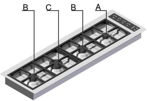
Overall view
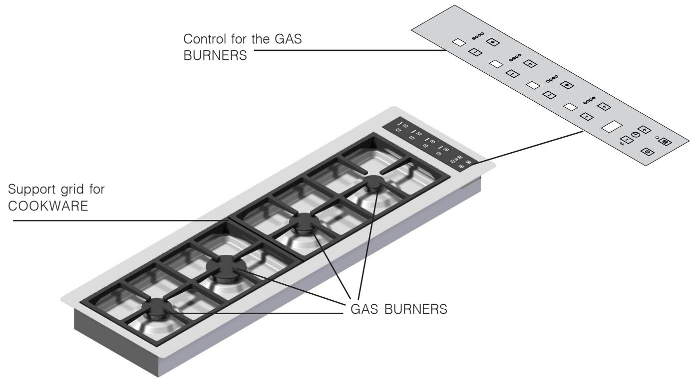
- GAS BURNERS differ in size and power. Select the most suitable burner in accordance with the diameter of the cookware you wish to use.
Control for the GAS BURNERS: used for flame or power adjustment. - GAS BURNER ignition enables a specific burner to be lit automatically.
- SAFETY DEVICE: stops the gas flow if the flame is accidentally extinguished.
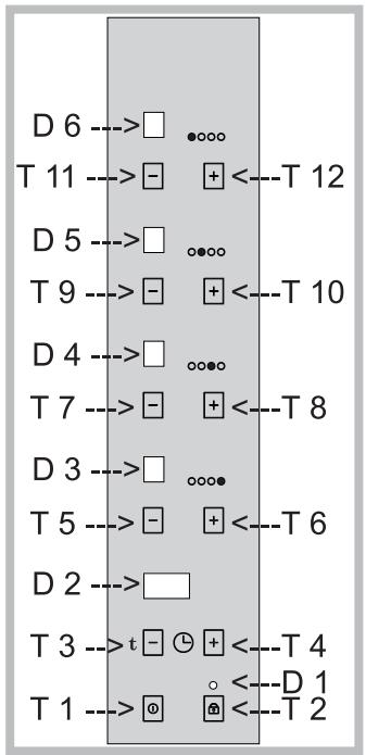
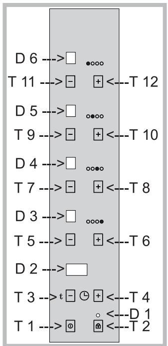
LEGEND: FUNCTION BUTTONS AND DISPLAY WINDOWS
T1 = ON/OFF
T2 = KEYPAD LOCK
T3 = - BUTTON USED TO SET TIMER AND SELECT GAS TYPE
T4 = + BUTTON USED TO SET TIMER AND SELECT GAS TYPE
T5 = - BUTTON USED TO IGNITE THE BURNER INDICATED ON THE GRAPHIC DISPLAY, AT THE MAX POWER LEVEL WITH SUBSEQUENT POWER REDUCTION UNTIL IT IS SWITCHED OFF.
T6 = - BUTTON USED TO IGNITE THE BURNER INDICATED ON THE GRAPHIC DISPLAY, AT THE MIN POWER LEVEL WITH SUBSEQUENT POWER INCREASE UNTIL IT REACHES THE MAX LEVEL.
T7 = - BUTTON USED TO IGNITE THE BURNER INDICATED ON THE GRAPHIC DISPLAY, AT THE MAX POWER LEVEL WITH SUBSEQUENT POWER REDUCTION UNTIL IT IS SWITCHED OFF.
T8 = + BUTTON USED TO IGNITE THE BURNER INDICATED ON THE GRAPHIC DISPLAY, AT THE MIN POWER LEVEL WITH SUBSEQUENT POWER INCREASE UNTIL IT REACHES THE MAX LEVEL.
T9 = - BUTTON USED TO IGNITE THE BURNER INDICATED ON THE GRAPHIC DISPLAY, AT THE MAX POWER LEVEL WITH SUBSEQUENT POWER REDUCTION UNTIL IT IS SWITCHED OFF.
T10 = + BUTTON USED TO IGNITE THE BURNER INDICATED ON THE GRAPHIC DISPLAY, AT THE MIN POWER LEVEL WITH SUBSEQUENT POWER INCREASE UNTIL IT REACHES THE MAX LEVEL.
T11 = - BUTTON USED TO IGNITE THE BURNER INDICATED ON THE GRAPHIC DISPLAY, AT THE MAX POWER LEVEL WITH SUBSEQUENT POWER REDUCTION UNTIL IT IS SWITCHED OFF.
T12 = + BUTTON USED TO IGNITE THE BURNER INDICATED ON THE GRAPHIC DISPLAY, AT THE MIN POWER LEVEL WITH SUBSEQUENT POWER INCREASE UNTIL IT REACHES THE MAX LEVEL.
D1 = LOCK ENABLED INDICATOR
D2 = COOKING TIMER AND SET TYPE OF GAS INDICATOR
D3 = POWER LEVEL INDICATOR (FROM 0 TO 9 = 10
POWER LEVELS + 0), BURNER HOT
INDICATOR (SIGNALLED BY A FLASHING H
WHEN THE BURNER IS SWITCHED OFF AND THE HOB SWITCHED ON, AND A FIXED H WHEN THE HOB IS SWITCHED OFF)
D4 = POWER LEVEL INDICATOR (FROM 0 TO 9 = 10
POWER LEVELS + 0), BURNER HOT
INDICATOR (SIGNALLED BY A FLASHING H
WHEN THE BURNER IS SWITCHED OFF AND
THE HOB SWITCHED ON, AND A FIXED H
WHEN THE HOB IS SWITCHED OFF)
D5 = POWER LEVEL INDICATOR (FROM 0 TO 9 = 10 POWER LEVELS + 0), BURNER HOT INDICATOR (SIGNALLED BY A FLASHING H WHEN THE BURNER IS SWITCHED OFF AND THE HOB SWITCHED ON, AND A FIXED H WHEN THE HOB IS SWITCHED OFF)
D6 = POWER LEVEL INDICATOR (FROM 0 TO 9 = 10
POWER LEVELS + 0), BURNER HOT
INDICATOR (SIGNALLED BY A FLASHING H
WHEN THE BURNER IS SWITCHED OFF AND
THE HOB SWITCHED ON, AND A FIXED H
WHEN THE HOB IS SWITCHED OFF)
THE FIRST TIME THE HOB IS CONNECTED TO THE ELECTRICITY MAINS, THE KEYPAD WILL BE LOCKED, AS IS THE CASE EVERY TIME ELECTRICITY IS RESTORED AFTER A BLACKOUT OR DISCONNECTION; THE T2 BUTTON SHOULD THEREFORE BE PRESSED IN ORDER TO UNLOCK THE KEYPAD.
AT THIS POINT THE APPLIANCE IS READY FOR OPERATION.
The burners differ in size and power. Select the most suitable burner in accordance with the diameter of the cookware you wish to use.
The oo symbols in the control area (M) indicate the position of the relevant burner on the hob.
The burners have thermocouple safety devices which offer protection against gas leaks. If the burner flame is extinguished during operation, the ignition device is activated in an attempt to re-ignite the flame. If this fails, after less than 6 seconds, the flow of gas to the burner is blocked and the corresponding display shows the text "F2".
Do not attempt ignition again for at least 1 minute, so that the escaped gas in the vicinity of the burner is able to disperse properly.
In some cases the non-ignition of a burner may be due to air which has become trapped in the gas piping. To make it easier for this air to escape, we recommend that one of the other burners is activated.
SWITCHING ON THE HOB
Press button T1 (general on/off device):
NOTE: the "on" status of the hob is indicated by the fact that all the burner displays show "0" (or a flashing "H" if the corresponding burner is hot due to previous use).
Press one of the buttons (+ or -) which corresponds to the burner you wish to ignite.
If the + button is pressed, the burner is ignited in its safety mode and after approximately 3 seconds automatically begins operating at its minimum power level; at this point, if you continue pressing the + button, it is possible to increase the power level until it reaches level 9 (max).
If the - button is pressed, the burner is ignited in its safety mode and after approximately 3 seconds begins operating at its maximum power level (power level 9) and remains there; at this point, if you continue pressing the - button, it is possible to decrease the power level until it reaches level 1 or the burner is switched off (level 0).
SWITCHING OFF A BURNER
Press the + and - buttons corresponding to the burner you wish to switch off simultaneously.
Alternatively:
Press the - button until level 0 is reached.
Alternatively:
Press button T1 (all burners switch off, even if the lock function has been activated; window D1 is activated).
SETTING A COOKING TIME
An operating duration may be set for one burner (the procedure can be performed on all burners but only one at a time; it is not possible to have several burners operating with a set duration).
The burner may be operating already or still switched off (it can only be switched on after the cooking duration has been set).
To select and set this option:
Press button T3; windows D3, 4, 5 and 6 flash alternately, displaying the symbol "t" and window D2 displays the figure "99" (the maximum time value which may be set).
Select the desired burner using + or -
Use timer buttons T3 and T4 to set the desired cooking time.
The power level indication appears on the "timed" burner as usual (although this may be modified during the operating period), interrupted every 10 seconds by the indication t;
At the end of the operating period, the burner switches off and a buzzer sounds;
The timer operating period can be set to a duration of anywhere between 0 and 99 minutes.
To shut of the timer function before the time has elapsed, press the - button (T3) until the value 0 is reached, or press the buttons + and - (T3 and T4) simultaneously.
ADDITIONAL NOTES
If a burner cannot be switched on or off, after attempting automatic re-ignition (for a maximum period of 6 seconds), the signal F2 (fault indication) will flash on the display corresponding to that burner.
When the hob is ON and the burners switched off, if no activity is detected on the keypad after 1 minute, a buzzer sounds and the keypad is locked (the display D1 is activated); after a further minute a buzzer sounds again and the hob switches off once and for all, with the keypad remaining locked.
Nevertheless, in every operating status (off, hob on and burners off, or hob and burners on), after 1 minute of inactivity on the keypad it will become locked.
After an hour of operation with no adjustments made to a particular burner, the burner will switch off.
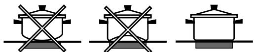
To achieve the maximum burner performance level, we recommend that only cookware with a suitable diameter for the relevant burner is used, thereby preventing the flame from leaking out from under the base of the pan (see table below).
Furthermore, when a liquid begins to boil, we recommend that the flame is reduced to the lowest level possible to keep the pan contents boiling.
BURNER 0 Pan diameter (cm)
A. Auxiliary 6-14
B. Semi-rapid 15-22
C.Rapid 18-26
To ensure the burners operate efficiently: All types of deep casserole dish may be used on the burners, as long as the edges of the cookware do not overlap the perimeter of the hob. The most important thing is that the base of the cookware is perfectly flat.
After a burner has been switched off, "H" will flash on the corresponding display to indicate that the burner is still hot.
If the hob is switched off (button T1), this signal will become fixed instead of flashing, until the burner has cooled completely.
When the appliance is not being used, make sure that it is switched off (the burner displays are switched off, or showing "H" if the burner is still hot).
We also recommend that the main valve on the gas supply piping is shut off.
! The appliance was designed and manufactured in compliance with international safety standards. The following warnings are provided for safety reasons and must be read carefully.
General safety
- This is a built-in appliance:
- Category II 2H3+ ; all models
- Class 1: all models with edges that are higher than 88 mm (see fig. 2, detail H3).
- Class 3: all models with edges that are lower than 88 mm (see fig. 2, details H1 and H2).
- Gas appliances require regular air exchange in order to maintain efficient operation. When installing the hob, follow the instructions provided in the paragraph relating to "Positioning" the appliance.
- These instructions are only valid for the countries whose symbols appear in the manual and on the serial number plate.
- The appliance was designed for domestic use inside the home and is not intended for commercial or industrial use.
- The appliance must not be installed outdoors, even in covered areas. It is extremely dangerous to leave the appliance exposed to rain and storms.
- Do not touch the appliance with bare feet or with wet or damp hands and feet.
- The appliance must be used by adults only for the preparation of food, in accordance with the instructions provided in this booklet.
- Make sure that the power supply cables of other electrical appliances do not come into contact with the hot parts of the oven.
- The openings used for the ventilation and dispersion of heat must never be covered.
Always make sure the knobs are in the "0" position when the appliance is not in use. - When unplugging the appliance, always pull the plug from the mains socket; do not pull on the cable.
- Never perform any cleaning or maintenance work without having disconnected the appliance from the electricity mains.
- If the appliance breaks down, under no circumstances should you attempt to perform the repairs yourself. Repairs carried out by inexperienced persons may cause injury or further malfunctioning of the appliance. Contact an Assistance Centre (see Assistance).
- Always make sure that pan handles are turned towards the centre of the hob in order to avoid accidental burns.
- Do not close the glass cover (if present) while the gas burners or electric hotplates are still hot.
- Do not use unstable or warped pans.
- As it is a potential hazard, make sure that children and disabled individuals do not have access to the glass
ceramic cooking zones (if present) during and immediately after cooking, as these zones remain hot for at least half an hour after they have been switched off.
- If the glass ceramic surface breaks, please contact any assistance centre which has been authorised by the manufacturer.
- If the glass ceramic surface breaks, it is best to disconnect the appliance from the electricity supply.
- Remove any liquids on the cover before opening it.
- The glass ceramic hob is resistant to mechanical shocks, but it may crack (or even break) if hit with a sharp object such as a tool. In these situations, or if cracks appear in the sealant, disconnect the appliance from the electricity network and contact an assistance centre which has been authorised by the manufacturer.
- Monitor any children to make sure they do not play with the appliance.
- This appliance is not intended for use by persons (including children) with reduced physical, sensory or mental capabilities or lack of experience and knowledge, unless they are supervised or trained by someone responsible for their safety.
- Intensive and prolonged operation of the appliance may require additional ventilation, for example a window should be opened or more efficient ventilation provided (the power of any mechanical ventilation system could be increased, for instance)
- The appliance is not intended to be operated by means of an external timer or separate remote control system.
Disposal
-
When disposing of packaging material: observe local legislation so that the packaging may be reused.
-
The European Directive 2002/96/EC relating to Waste Electrical and Electronic Equipment (WEEE) states that household appliances should not be disposed of using the normal solid urban waste cycle. Exhausted appliances should be collected separately in order to optimise the cost of re-using and recycling the materials inside the machine, while preventing potential damage to the atmosphere and to public health. The crossed-out dustbin is marked on all products to remind the owner of their obligations regarding separated waste collection.
Exhausted appliances may be collected by the public waste collection service, taken to suitable collection areas in the area or, if permitted by current national legislation, they may be returned to the dealers as part of an exchange deal for a new equivalent product.
All major manufacturers of household appliances participate in the creation and organisation of systems for the collection and disposal of old and disused appliances.
Switching the appliance off
Disconnect your appliance from the electricity supply before carrying out any work on it.
Cleaning the appliance
! Do not use abrasive or corrosive detergents such as stain removers, anti-rust products, powder detergents or sponges with abrasive surfaces: these may scratch the surface beyond repair.
! Never use steam cleaners or pressure cleaners on the appliance.
- It is usually sufficient simply to wash the hob using a damp sponge and dry it with absorbent kitchen towel.
- The removable parts of the burners should be washed frequently with warm water and soap and any burnt-on substances removed.
- For hobs which light automatically, the terminal part of the electronic instant lighting devices should be cleaned frequently and the gas outlet holes should be checked for blockages.
- Stainless steel can be marked by hard water that has been left on the surface for a long time, or by aggressive detergents containing phosphorus. After cleaning, rinse well and dry thoroughly. Any remaining drops of water should also be dried.
Gas tap maintenance
Over time, the valves may become jammed or difficult to turn. If this occurs, the valve must be replaced.
! This procedure must be performed by a qualified technician who has been authorised by the manufacturer.
It may happen that the appliance does not function properly, or even at all. Before calling the service centre for assistance, check if anything can be done. First check to see that there are no interruptions in the gas and electrical supplies, and, in particular, that the gas valves for the mains supply are open.
Problem
The burner does not light or the flame is not even.
The flame dies in models with a safety device.
The burner does not remain lit when set to minimum.
The cookware is unstable.
Possible causes / Solutions:
- The gas holes on the burner are clogged.
- All the movable parts that make up the burner are assembled correctly.
- There are draughts near the appliance.
-
The gas holes are blocked in the area corresponding to the safety device.
-
The gas holes are blocked.
-
There are draughts near the appliance.
-
The minimum setting has not been adjusted properly.
-
The bottom of the cookware is perfectly flat.
- The cookware is positioned correctly at the centre of the burner.
- The pan support grids have been positioned correctly.
If, despite all these checks, the hob does not function properly and the problem persists, call the nearest Customer Technical Assistance Centre. Please have the following information to hand:
- The appliance model (Mod.).
- The serial number (S/N).
This information can be found on the data plate located on the appliance and/or on the packaging.
! Never use the services of unauthorised technicians and never accept replacement parts which are not original.
T
Italiano, 1
GB
English, 16
FR
Français, 31
ES
Espanol, 46
PT
Portugués, 61
B 40 L EC...
Sommaire
Installation, 32-38
Positionnement