GGS75WAX - Cooker GORENJE - Free user manual and instructions
Find the device manual for free GGS75WAX GORENJE in PDF.

| Product type | Gas range |
| Brand | Gorenje |
| Model | GGS75WAX |
| Power source | Natural gas (G20/G25) convertible to propane/butane |
| Number of burners | 4 (including one wok burner) |
| Burner types | Simmer, normal, powerful, wok burner |
| Oven | Integrated gas oven |
| Cooktop material | Enameled deep pan |
| Controls | Removable rotary knobs |
| Safety | Taps with thermal safety |
| Gas conversion | Possible with conversion kit (injectors and economy screws) |
| Cleaning | Removable enameled deep pan for cleaning |
| Maintenance | Checking injectors and seals |
| Spare parts | Injectors, economy screws, seals, rating plates |
| Repairability | Conversion by qualified technician recommended |
| Installation | Gas and electrical connection, leveling |
| Dimensions (approx.) | Width 60 cm, Depth 60 cm, Height 85 cm |
| Weight (approx.) | 50 kg |
| Electrical supply | 230 V, 50 Hz |
Frequently Asked Questions - GGS75WAX GORENJE
User questions about GGS75WAX GORENJE
0 question about this device. Answer the ones you know or ask your own.
Ask a new question about this device
Download the instructions for your Cooker in PDF format for free! Find your manual GGS75WAX - GORENJE and take your electronic device back in hand. On this page are published all the documents necessary for the use of your device. GGS75WAX by GORENJE.
USER MANUAL GGS75WAX GORENJE
Conversion instruction
Adjusting for a different gas type
Consigne de conversion
Instilling for annen gasstype
Introduction (A) 4
Dismantling (B) 5
Converting (C) 5
Check for gas tightness and operation (D) 6
Final assembly 7
Start up 7
Checking operation (E) 8

Attention: Performing of these instructions by a non-qualified engineer can lead to dangerous situations
The supplier is not responsible for the consequences (the arising of a hazardous situation and/or damage to persons or goods) caused by incorrect performance of these instructions by engineers who are not employees of the supplier. Consequential damage arising through inexpert performance of these instructions is not accepted.
This conversion-set consists of original parts. Original parts are tested for suitability and safety during the type approval of the appliance. Frequently performed batch-approvals guarantee the quality of original parts.
The supplier recommends, when converting an appliance to another gas type, to have this performed by an engineer of the service department.
Contact the supplier to make an appointment with a service engineer.
For addresses see the guarantee regulations of the appliance.
Introduction (A)
With this conversion-set you can convert your gas hob from natural gas (G20/ G25) to propane/butane gas. Before you start conversion, check whether your gas hob is genuinely set to natural gas.
Tools

7

4

T20

P2
A. Socket spanner
B. Screw driver flat blade
C. Screw driver Torx
D. Screw driver cross head
E. Nose pliers

7

F. Open end spanner
G. Leakage test spray
Contents of conversion set:
- Injectors for the burners (see illustration A1, at the back of this instruction);
- Simmer setting screws for the gas taps;
- Gaskets;
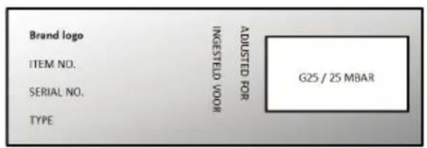
- Three data labels with the modified gas setting;
• Fiber rings for enamelled appliances; - Silicon sealing plugs.
Dismantling (B)

Please note: disconnect the appliance from the power supply before you remove the drip tray. Prevent damage of the worktop. Lay down parts of the appliance on a protected base.
- Remove the pan supports, burner heads and burner cups. Pull off the control knobs vertically and remove them.
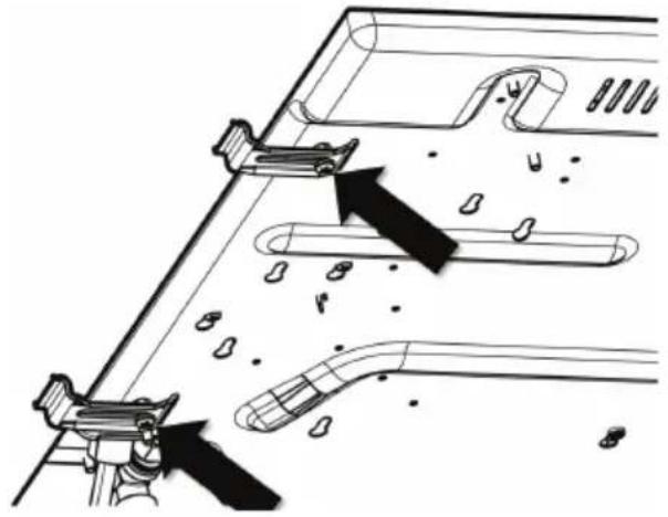
- Loosen the screws of the mounting brackets at the underside of the appliance (see illustration B1, at the back of this instruction).
- Unscrew the screws that are holding the burners (see illustration B2, at the back of this instruction).
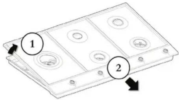
- Lift the drip tray on the back of the appliance, dismount the earth wire (if applicable), and slide the drip tray to the front (see illustration B3, at the back of this instruction).
- Remove the drip tray.
Converting (C)
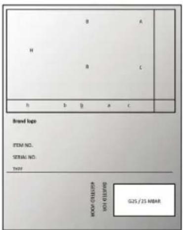
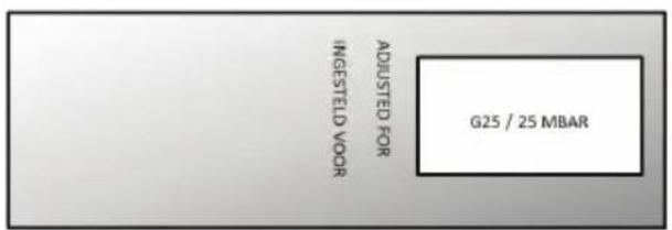
For verification, you can find the values of the injector and simmer setting screws on the holder of the injectors. The characters of the sets correspond with the characters on the label inside the lower tray of the appliance (upper case characters for injectors and lower case characters for simmer setting screws). The values are also indicated on the injectors and simmer setting screws (see table 1, at the back of this instruction).
The following sets can occur:
- Set 'A-a' for auxiliary burner;
- Set 'B-b' for semi rapid burner;
- Set 'C-c' for rapid burner;
- 'H1-h', 'H2' and 'J-j' sets for wok burner.

It is possible that not all the injectors in the set will be used for the conversion of your appliance.
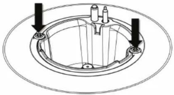
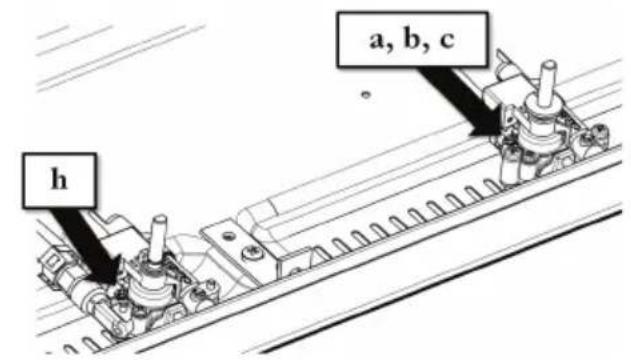
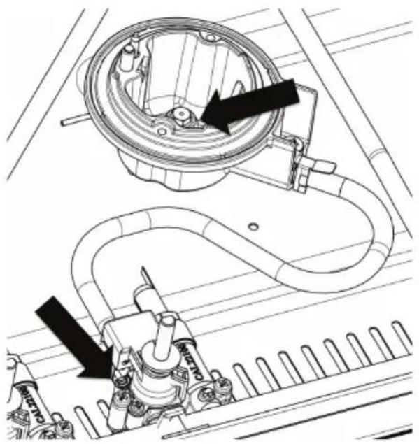
- Replace the injectors in the burners.
Use a socket spanner (7) for disassembling/assembling the injectors in the burners (see illustration C2, at the back of this instruction). - Replace the simmer setting screws in the taps.
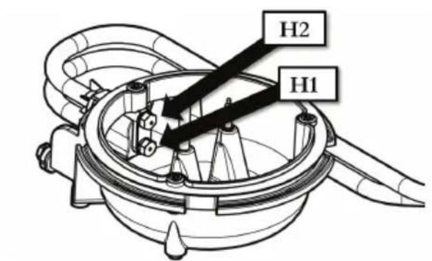
Use a screwdriver, flat-blade 4, for disassembling/assembling of the simmer setting screw (see illustration C4, at the back of this instruction) and when necessary use pliers. - On the wok burner, replace the injectors for outer (H1) and inner (H2) burner using an open end spanner (7).
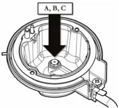
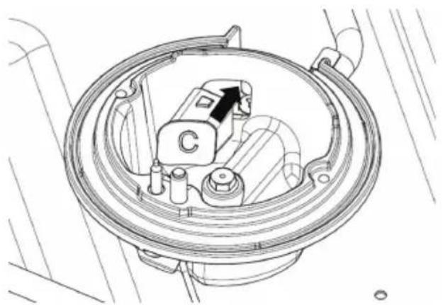
The injector for the outer burner is the one at the bottom, the upper injector is for the inner burner. (Illustration C3, at the back of this instruction) - Install the silicon sealing plugs, marked with a letter A, B and C in the air holes of the corresponding burners (see illustration C7).
If applicable (see table 1, at the back of this instruction). - Place the label 'H1' in the appropriate box on the current appliance identification card in the bottom tray of the appliance (see illustration C1, at the back of this instruction).
- Place the label 'H2' in the appropriate box on the current appliance identification card at the underside of the appliance (see illustration C5).
- Place the label 'G2' in the appropriate box on the current appliance identification card on the back of the user manual (see illustrations C6, at the back of this instruction).
Check for gas tightness and operation (D)
When the appliance is connected to the gas supply, use leakage test spray to check the gas tightness:
- Seal the injector.
- Open the gas tap.

Attention; press and open tap with thermo electric safety device and keep it pressed down.
-
Spray leakage test spray on the connections and check for gas tightness (see illustration D, at the back of this instruction).
-
Repeat for every burner.
When the appliance is not connected to the gas supply, check the gas tightness with a pressure pump:
- Connect the pressure pump to the gas pipe and close all gas taps.
- Increase the pressure to 150 mbar and close the tap between the pressure pump and the pressure gauge. Check the pressure. The maximum pressure drop is allowed up to 5 mbar per minute. After checking, open the tap between the pressure pump and the pressure gauge. Open one of the taps and close the corresponding injector.

Attention; press and open a tap with thermo electric safety device and keep it pressed down.
- Increase the pressure to 150 mbar and again close the tap between the pressure pump and the pressure gauge. Check the pressure. The maximum pressure loss may amount to 5 mbar per minute.
- Repeat for every burner.
Final assembly
- Replace gaskets on top of the burners.
- Place the drip tray on the appliance starting with the front side. The hooks on the front of the drip tray must be placed under the edge of the under tray. For enamelled drip trays, do not forget to connect the earth cable to the drip tray.
- Install the screws around the burner to secure the drip tray. For enamelled drip trays, use new fiber rings under the screws.
- Tighten the screws of the brackets at the underside of the appliance.
Start up
- Install the knobs, the burner parts and pan supports.
- Check whether the appliance is connected to the correct type of gas and gas pressure.
- Open the main gas valve and insert the plug into the power socket.
Checking operation (E)
- Ignite the burners.
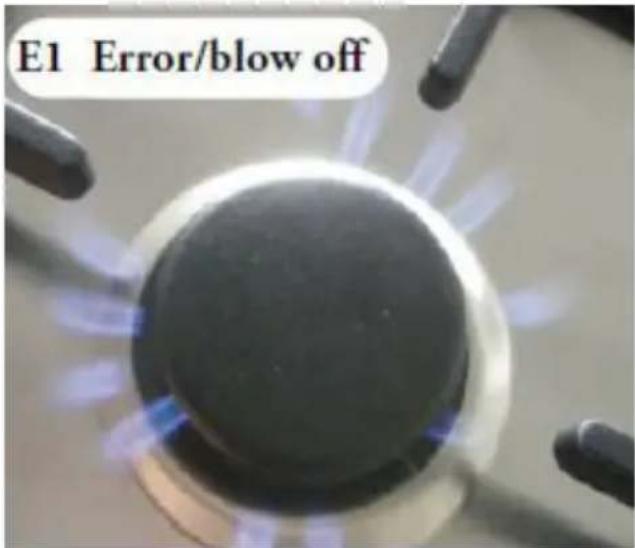
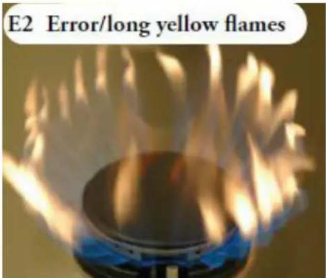
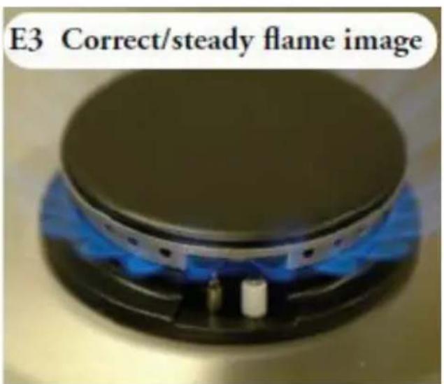
- Check whether the flame profile is uniform and stable for the complete ratio (see illustrations E1, E2 en E3, at the back of this instruction).
- Check if the flame does not smother in simmer rate;
- Check if the flames are not ‘blowing off’ at maximum rate;
- No long, yellow flames should be visible during operation.
SOMMAIRE
F. Schraubenschlüssel

[Non-Text]
natural_image
Line drawing of six identical mechanical components arranged in a cluster (no text or symbols)A1
natural_image
Technical diagram showing mechanical assembly with arrows indicating motion or force direction (no text or symbols)B1
natural_image
Technical diagram of a mechanical component with two arrows indicating assembly or alignment (no text or symbols present)B2
B3
C1
C2
C3
C4
C5
C6
natural_image
Technical line drawing of a mechanical component with no visible text or symbolsC7
natural_image
Technical diagram of a mechanical assembly with two views showing internal components and directional arrows (no text or labels)D1
Table 1
| Gas | P (mBar) | A | a | B | b | C | c | H1 | H2 | h | Plug |
| G20 | 20 | 0.75 | 0.40 | 1.05 | 0.45 | 1.27/ 1.20 | 0.53 | 1.51 | 0.55 | 0.40 | |
| G25 | 25 | 0.77 | 0.40 | 1.08 | 0.45 | 1.34 | 0.53 | 1.56 | 0.55 | 0.40 | |
| G30 | 30 | 0.46 | 0.26 | 0.6 | 0.30 | 0.72 | 0.36 | 0.93 | 0.26 | 0.40 | √ |