
AV Bridge 2x1 - Commutateur audiovisuel Vaddio - Free user manual and instructions
Find the device manual for free AV Bridge 2x1 Vaddio in PDF.


| Product Type | Presentation Switcher / AV Bridge |
| Brand | Vaddio (Legrand AV) |
| Model | AV Bridge 2x1 |
| Video Inputs | 2x HDMI (HDCP supported) |
| Video Outputs | 1x HDMI, 1x USB 3.0, IP streaming (RTSP/RTMP) |
| Audio Inputs | 2x Mic/Line (with phantom power), 2x HDMI audio, Dante (up to 4 inputs) |
| Audio Outputs | 2x Line, HDMI audio, Dante (up to 4 outputs), USB record, IP stream |
| USB Streaming | USB 3.0, up to 1080p/60, always enabled |
| IP Streaming | Up to 1080p/30, RTSP or RTMP, enable/disable via web |
| Power | PoE+ (Power over Ethernet Plus) via included injector |
| Control Interfaces | Front panel buttons, web interface (HTTPS), RS-232, Telnet, serial API, Vaddio Deployment Tool |
| Mounting | Half-rack width (mounting kit included), optional dual half-rack and under-table mounts |
| Operating Temperature | 0°C to 40°C (32°F to 104°F) |
| Storage Temperature | 0°C to 40°C (avoid temperatures above 40°C or below 0°C) |
| Compliance | FCC Part 15 Class A, ICES-003 Class A, CE |
| Included Accessories | PoE+ injector with AC cord(s), half-rack mounting kit, 4x Phoenix connectors, Cat-5 cable (0.9 m), USB 3.0 cable (1.8 m), Quick-Start Guide |
| Care and Cleaning | Wipe with clean, soft cloth. Do not use abrasive chemicals. Keep away from liquids. |
| Safety | Indoor use only. Do not install in humid environment without protective enclosure. Do not expose to liquids. |
| Repairability | No user-serviceable parts inside. Contact Vaddio technical support for service. |
Frequently Asked Questions - AV Bridge 2x1 Vaddio
User questions about AV Bridge 2x1 Vaddio
0 question about this device. Answer the ones you know or ask your own.
Ask a new question about this device
Download the instructions for your Commutateur audiovisuel in PDF format for free! Find your manual AV Bridge 2x1 - Vaddio and take your electronic device back in hand. On this page are published all the documents necessary for the use of your device. AV Bridge 2x1 by Vaddio.
USER MANUAL AV Bridge 2x1 Vaddio
Complete Manual for the
AV Bridge 2x1
Presentation Switcher
Document 411-0042-30 Rev A
March 2020
Contents
Overview 1.
About this Guide.1....
Features 1
Unpacking the AV Bridge 2x1.2....
A Quick Look at the AV Bridge.2x1.3....
Front Panel 3.
Connector Panel 4.
Installation 5.
Don't Void Your Warranty! 5.
Cabling Notes.5....
Basic Connections.... 6
Basic Connections for Conferencing 7
Using Dante Devices with AV Bridge .2x1.... 7
RS-232 Serial Communication Settings and Port Pin-outs 8
Powering Up....8
Initial Device Set-Up and System Administration Tasks....9
About the Web Interface.... 10
Browser Support 10
About the Vaddio Deployment Tool 10
Initial Device Set-Up from the Web Interface.... 11
Getting the Device's IP Address.... 11
Initial Access to the Web Interface.... 11
Setting up the Web Interface.13....
Initial Device Set-Up Using the Vaddio Deployment.Tool 14
Next Steps for New Deployments.... 15
Setting Passwords and Access.... 16
Configuring Other Security Settings.... 17
For Non-DHCP Environments: Configuring the Device with a Static IP Address 18
Changing the Device's Hostname.... 18
Optional For DHCP Environments: Changing from a DHCP Address to a Static IP Address ... 19
Adding Room Information.... 19
Setting System Time and Time Zone 20
Identifying Dante Devices.... 21
Performance and Behavior Settings.... 23
Configuring Audio Settings 24
Muting and Setting Volume 25
Microphone Settings and Adjustments 26
Enabling Phantom Power to Microphones 27
Speaker Adjustments.... 28
Synchronizing Audio with Video in the IP Stream 29
Routing Audio 30
Setting Gain Between Input and Output (Crosspoint Gain).31
Configuring Streaming Settings 32
Supported Input Resolutions and Frame Rates 32
Configuring USB Streaming 32
Set IP Streaming Video Settings 33
RTSP Streaming Settings 35
RTMP Streaming Settings 36
Stopping the IP Stream 37....
Advanced: Changing MTU 37
Working with Video Inputs 38
Configuring the Video Output 38....
Setting Video Transition Type and Speed 39
Working with Graphics.... 39
Setting up Macros and Triggers 40
Configuring Standby Behavior 41
Locking the Front Panel 41
Customizing Labels 42
System Maintenance 43
Exporting and Importing Configuration Data 43
Updating the Firmware 45
Rebooting 46
Contacting Vaddio Technical Support 47
Viewing Diagnostic Logs 47
Operating the AV Bridge 2x1 48
About Viewing Streams 48
Muting and Video: Quick Steps You Can Take from Any Page 49
Working with Cameras 50
Working with Camera Presets 50
Controlling Movement 50
Working with Audio 51
Working with Macros 51
Going to Standby (Low Power) Mode 52
Serial Command API 53
audio volume 54
audio mute 55
audio route 56
audio crosspoint-gain 57
streaming settings get 58
streaming ip enable 59
camera home 59
camera pan 60
camera tilt_60
camera zoom.61....
camera preset 62
camera ccu get 63....
camera ccu set 64
camera ccu scene 65
camera focus 66
camera comm host 67....
camera standby 67
video program pip.68....
video mute 69
video type 69
trigger .70....
network ping....70
network settings get 71
system standby 71
system reboot 71
system factory-reset 72
version 72
history 73
help 73
exit 73
Specifications 74
Troubleshooting and Care 75
Power Issues 75
Control Issues 76
Network and Communication Issues 76
Video and Audio Issues 77
Restoring Factory Defaults 77
Restoring Factory Defaults from the Web Interface 77
Restoring Factory Defaults from the Front Panel 77
Operation, Storage, and Care 78
Glossary 79
Compliance and Conformity Statements 82
FCC Part 15 Compliance 82
ICES-003 Compliance 82
European Compliance 83
Photo Credits 84
Index 85
Overview
This guide provides information about the AV Bridge 2x1 presentation
switcher:
■ 999-8250-000 – North America
■ 999-8250-001 – Europe/UK
■ 999-8250-009 – Australia/New Zealand

About this Guide
This guide covers:
■ Unpacking and installing the device
■ The device's physical features and user interfaces
■ Administration and configuration tasks
Operation
■ Serial API command reference
■ Specifications
■ Troubleshooting and maintenance
■ Glossary
■ Compliance/conformity information
For your convenience, information on installing this product is also available in the smaller, stand-alone Installation Guide for the AV Bridge 2x1 Presentation Switcher, which covers unpacking, physical features, switch settings, installation, and initial power-up.
Features
■ The perfect solution for rooms where you only need two cameras: 2x1 video switcher bridges two HDMI cameras or other video sources into a soft-client conferencing or IP streaming environment
■ Simultaneous USB 3.0 and IP streaming (RTSP or RTMP), video and audio
■ Delivers IP stream resolution up to 1080p/30 and USB stream resolution up to 1080p/60
■ Supports HDCP
■ Multiple audio formats: USB and IP stream, analog, HDMI,®Dante
■ Phantom power to microphones
■ Connections for up to five external trigger devices
Unpacking the AV Bridge 2x1
Make sure you received all the items you expected. Here is the packing list for the AV Bridge 2x1.
AV Bridge 2x1, North America: 999-8250-000
AV Bridge 2x1, Europe and UK: 999-8250-001
AV Bridge 2x1, Australia and New Zealand: 999-8250-009
■ AV Bridge 2x1
■ PoE+ power injector with AC cord set(s)
■ Half-rack mounting kit
■ 3-position Phoenix-style connectors (qty. 4)
■ Cat-5 cable, 3 ft (0.9 m)
■ USB 3.0 cable, type A to type B, 6 ft (1.8 m)
■ Quick-Start Guide
Optional dual half-rack and under-table mounts are also available on legrandav.com. Contact us if you can't find the mount you need.

natural_image
Product photo of a vaddia air bridge 241 connected to various electronic components including connectors, cables, and electrical socket (no readable text or symbols)A Quick Look at the AV Bridge 2x1
Physical features of the device – controls, indicators, and connectors.
Front Panel
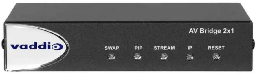
Swap button:
- Changes the selected input.
- Exchanges the PIP and main image on the HDMI output, if the PIP is turned on.
- PIP button:
- Toggles the PIP on or off.
- Illuminated: PIP is on.
Off: PIP is off.
- Toggles the PIP on or off. - Illuminated: PIP is on. - Off: PIP is off.
■ Stream button:
- Toggles the stream on or off.
- Illuminated: Stream is available.
- Off: Stream is not available.
IP button:
- Press to display the device's IP address in the streams. Press again to dismiss the IP address information.
- Illuminated: Streams and local HDMI output are displaying the IP address.
- Off: Normal display.
■ Reset button:
- Press to reboot the device.
- Illuminated: Normal operation.
- Off: No power to the device.
- Blinking: Error.
■ Dimensionally enhanced puffy badge: We have spared no expense to provide a lovely, dimensionally enhanced logo badge to elevate your visual experience. It's quite shiny. We hope you'll enjoy it.
Connector Panel
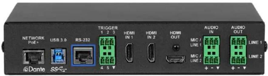
■ Network/PoE+ – Power, control via web interface, Dante audio, and IP streaming.
■ USB 3.0 – Uncompressed video output with PCM audio for conferencing applications.
■ RS-232 – Connect to an optional third-party control system.
- Trigger – Connect up to five trigger devices.
■ HDMI In 1 and HDMI In 2 – HDMI video (and audio, if available) from the connected camera or other HDMI source.
■ HDMI Out – Output video (and audio, if available) from the selected input.
- Audio In Mic/Line 1 and Mic/Line 2 – Microphone or other audio inputs. Can be configured to supply phantom power.
■ Audio Out Line 1 and Line 2 – Far-end audio from conferencing application or as configured in the audio matrix.
Installation
This section covers how to install and connect the product. It also provides safety information and other guidance related to installing the product.
Note
This product is intended for installation and use only in environments where all RS-232 and PoE connections originate within the building.
Or in UL's preferred phrasing...
PoE-type networks connected to this equipment are for intra-building use only and should not be connected to lines that run outside the building in which this product is located.
Don't Void Your Warranty!
Caution
This product is for indoor use. Do not install it outdoors or in a humid environment without the protective enclosure. Do not allow it to come into contact with any liquid.
Do not install or operate this product if it has been dropped, damaged, or exposed to liquids. It is things happen, return it to Vaddio for safety and functional testing.
Cabling Notes
Use Cat-5e or better cable and standard RJ-45 connectors (568B termination). We recommend using high-quality connectors and a high-quality crimping tool.
Caution
When building cables for Vaddio products, do not use pass-through RJ-45 connectors. If they are crimped incorrectly, they can cause intermittent connections and degrade signal quality. Incorrectly crimped pass-through connectors can also damage the connectors on the product, which will void your warranty.

Intact – will make reliable contact with cable connector

Damaged – Bent contact fingers will NOT make reliable contact with cable connector
Use Cat-5e or better cable. We recommend using high-quality connectors and a high-quality crimping tool. We recommend shielded cabling if the cables will be coiled, run tightly with other cables, or placed close to sources of electromagnetic interference such as power lines.
Caution
Check your cables. Connecting a cable to the wrong port or using the wrong pin-out can result damage and will void the warranty.

Pro Tip
To prevent tragic mishaps, label both ends of every cable.
Basic Connections
This diagram shows a basic installation. Cameras or other HDMI sources may be used for both HDMI inputs. The AV Bridge 2x1 does not power the speaker(s). The HDMI output displays video from the selected source; the picture-in-picture (PIP) is from the video source not currently selected – a camera, laptop, or other video source.

flowchart
graph TD
    A["Network"] -->|Data & Power OUT| B["Device"]
    B --> C["Power"]
    B --> D["PoE+"]
    B --> E["Network"]
    B --> F["Video"]
    B --> G["Audio"]
    C --> H["Speaker Line 1"]
    D --> I["Speaker Line 2"]
    E --> J["Speaker Line 3"]
    F --> K["Speaker Line 4"]
    G --> L["Speaker Line 5"]
    H --> M["Micro Line 1"]
    I --> N["Micro Line 2"]
    J --> O["Micro Line 3"]
    K --> P["Micro Line 4"]
    L --> Q["Micro Line 5"]
    M --> R["Micro Line 6"]
    N --> S["Micro Line 7"]
    O --> T["Micro Line 8"]
    P --> U["Micro Line 9"]
    Q --> V["Micro Line 10"]
    R --> W["Audio IN"]
    S --> X["Audio OUT"]
    T --> Y["Audio IN"]
    U --> Z["Audio OUT"]
Basic Connections for Conferencing
Add a laptop and a second HDMI display for conferencing.
In this diagram, the laptop connects to the room's main display, which shows the far-end video from the soft conferencing application on the laptop. (In contrast to the previous diagram, our friend at the podium is on the far end of the call.) The soft conferencing application manages the PIP(s) in this image. The display connected to the HDMI output shows near-end video.
The HDMI output from the AV Bridge 2x1 goes to a "confidence display" showing near-end video only. The image on this display is used as the near-end PIP on the main display. If the PIP is enabled on the AV Bridge 2x1, this is part of the image that others in the conference will see, and the room's main display shows a PIP within the near-end PIP.

flowchart
graph TD
    A["Network"] --> B["Data & Power OUT"]
    B --> C["Device 1"]
    B --> D["Device 2"]
    C --> E["TRIGGER 1 2 3"]
    D --> F["TRIGGER 1 2 3"]
    E --> G["USB 3.0"]
    F --> H["USB 3.0"]
    G --> I["RS-232"]
    H --> J["RS-232"]
    I --> K["4.5"]
    J --> L["4.5"]
    K --> M["4.5"]
    L --> N["4.5"]
    M --> O["4.5"]
    N --> P["4.5"]
    O --> Q["4.5"]
    P --> R["4.5"]
    Q --> S["4.5"]
    R --> T["4.5"]
    S --> U["4.5"]
    T --> V["4.5"]
    U --> W["4.5"]
    V --> X["4.5"]
    W --> Y["4.5"]
    X --> Z["4.5"]
    Y --> AA["4.5"]
    Z --> AB["4.5"]
    AA --> AC["4.5"]
    AB --> AD["4.5"]
    AC --> AE["4.5"]
    AD --> AF["4.5"]
    AE --> AG["4.5"]
    AF --> AH["4.5"]
    AG --> AI["4.5"]
    AH --> AJ["4.5"]
    AI --> AK["4.5"]
    AJ --> AL["4.5"]
    AK --> AM["4.5"]
    AL --> AN["4.5"]
    AM --> AO["4.5"]
    AN --> AP["4.5"]
    AO --> AQ["4.5"]
    AP --> AR["4.5"]
    AQ --> AS["4.5"]
    AR --> AT["4.5"]
    AS --> AU["4.5"]
    AT --> AV["4.5"]
    AU --> AW["4.5"]
    AV --> AX["4.5"]
    AW --> AY["4.5"]
Using Dante Devices with AV Bridge 2x1
The AV Bridge 2x1 presentation switcher is compatible with Dante audio products. These products connect to the AV Bridge 2x1 over the network.
To work with Dante devices, you will need to download and install the free Dante Controller application from Audinate Pty. Ltd.:
www.audinate.com/products/software/dante-controller
Things to know about Dante Controller:
■ Dante Controller does not work over Wi-Fi or across subnets. Your computer must be on the same subnet as the Dante devices you need to work with.
■ Device names and IP addresses shown in Dante Controller do not match the corresponding information shown in Vaddio devices' web interfaces.
■ Dante Controller allows you to rename devices, so you can make their identifying labels match what's displayed in the Vaddio web interface.
Audinate provides information, training, and documentation for Dante technology on their website.
RS-232 Serial Communication Settings and Port Pin-outs
The RS-232 serial port (color-coded blue) on the back panel connects to a third-party controller.
RS-232 connector pin-out:
■ Pin 1: Not used
■ Pin 2: Not used
■ Pin 3: Not used
■ Pin 4: Not used
■ Pin 5: Not used
■ Pin 6: GND
■ Pin 7: TXD
■ Pin 8: RXD

Communication parameters:
| Parameter Value | |
| Communication Speed 38400 bps | |
| Start bits 1 | |
| Stop bits 1 | |
| Data bits 8 | |
| Parity None | |
| Flow control None | |
Caution
Check your cables. Connecting a cable to the wrong port or using the wrong pin-out can result damage and will void the warranty.
Depending on the equipment connected to the RS-232 port, you may need a null-modem (crossover) cable.
Powering Up
Power up the AV Bridge 2x1 and the connected equipment at the same time, or power up the connected equipment before you power up the AV Bridge 2x1.
Initial Device Set-Up and System Administration Tasks
When any Vaddio product is shipped from the factory, there is no admin password and the administrative controls are not available. This is also true if you restore factory defaults, which returns the device to a "like new" state.
Initial device set-up includes setting the admin password, and may include additional tasks.
There are two ways to access the AV Bridge 2x1 device for initial device set-up:
- Access the Initial Device Set-up page of the web interface directly – You must know the IP address of the device so you can browse to its web interface. See Web Interface.
- Locate and set up the product using the Vaddio Deployment Tool – This tool is available as a free download at https://info.legrandav.com/VaddioDeploymentTool. The tool scans the network for Vaddio devices, lists them by model and IP address, identifies all devices that are not set up, provides the controls to complete the initial device set-up, and provides links to each device's web interface. See Vaddio_Deployment_tool.
After initial device set-up is complete, you will also need to complete system administration tasks to define how the device behaves as an element of your network.
■ Network settings – Depending on the requirements of your network, the device's default network settings may need to be changed. Work with the site's network specialist to determine the right settings.
■ Security settings – Depending on the organization's security requirements, some of these settings may need to change.
■ Time zone – Set the device to the appropriate time zone to ensure that timestamps in the event log are accurate.
- Room labels – Add helpful information such as the room location and phone number to the web interface of each device.
- Dante device identification – Use the Dante Controller application to locate and optionally rename the Dante devices in your installation.
About the Web Interface
The AV Bridge 2x1 presentation switcher provides a web interface to allow configuration via the IP network connection, using a browser. The web interface allows you to:
■ Set idle session behavior and passwords
■ Manage network and streaming settings
■ Add identifying information to the web interface
■ Back up, reboot, reset, or update the device
■ View information about the device's firmware and current settings
You can access the web interface either through the network or from a computer connected directly to the network port. If the device has never been in service, or if factory defaults have been restored, you will need to do the initial setup before you can access the rest of the web interface.
Browser Support
Supported web browsers:
Chrome®
■ Firefox®
■ Microsoft® Internet Explorer®
■ Safari®
Other browsers may also work.
About the Vaddio Deployment Tool
The Vaddio Deployment Tool simplifies provisioning and system administration for most Vaddio products, and provides a shortcut to each device's web interface. This tool is available as a free download at https://info.legrandav.com/VaddioDeploymentTool.
Ways the Vaddio Deployment Tool makes your tasks easier:
- Easily scan your network for Vaddio devices – no more complicated procedures for discovering devices' IP addresses.
■ View scan results as a dashboard; easily identify unprovisioned and unauthenticated devices.
■ Provision new devices or update device firmware from the dashboard. - Import or export device configurations, reboot, or restore a device to factory defaults from its detail page.
■ Access devices' web interfaces directly.
■ Change a device's admin password from its detail page.
■ Standby and mute controls available on the dashboard for authenticated devices. - Organize Vaddio devices into groups – for example, by product type or physical location.
Initial Device Set-Up from the Web Interface
To complete the initial device set-up from the web interface, you will need to do these things:
■ Discover the device's IP address. If you do not use the Vaddio Deployment Tool, you will need to be able to view the HDMI output.
■ Browse to the device's IP address using HTTPS. This will generate warnings from your browser.
■ Complete the initial device set-up.
Getting the Device's IP Address
To see the current IP address for the AV Bridge 2x1, press the IP button on the front panel. The IP address and other network information is displayed on the video outputs.
If the IP address is 169.254.1.1, you will need to connect your computer's network port directly to the DATA IN port of the device's mid-span power injector. After completing the initial device set-up, you will need to configure the device with a static IP address. Work with your network administration.
Initial Access to the Web Interface
Before the product is configured, HTTP access is disabled. This is also true after restoring factory defaults. When you access the web interface, you may encounter this message:
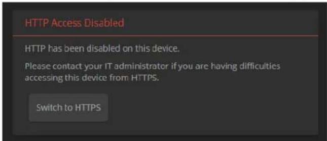
Switch to HTTPS if you see this message.
Expect a security warning from your browser the first time you access the device's web in. Different browsers will respond with different messages and options. Your browser will probably present a message indicating one of these things:
■ The connection is not private
■ The site is not secure
■ The site is not trusted
■ The site poses a security threat
This is because the certificate (the product's website security credential) is self-signed rather than being issued by an external certificate authority. The HTTPS connection is secure and traffic is encrypted, however.
You will need to make the selections that your browser's security message discourages. Depending on the browser, the warning presents an option to learn more, view details, or go to the "Advanced" page. When you select this, your browser provides an explanation and a button or link to continue to the IP address you entered, with a reminder that it may be unsafe. Select the option to continue. Your HTTPS connection is safe.
Here is a sample HTTPS warning page from Firefox, showing the "Advanced" information:

Warning: Potential Security Risk Ahead
Firefox detected a potential security threat and did not continue to 10.30.20.94. If you visit this site, attackers could try to steal information like your passwords, emails, or credit card details.
What can you do about it?
The issue is most likely with the website, and there is nothing you can do to resolve it.
If you are on a corporate network or using anti-virus software, you can reach out to the support teams for assistance. You can also notify the website's administrator about the problem.
Learn more...
Go Back (Recommended)
Advanced...
Websites prove their identity via certificates. Firefox does not trust this site because it uses a certificate that is not valid for 10.30.20.94.
Error code: SEC_ERROR_UNKNOWN_ISSUER
View Certificate
Go Back (Recommended)
Accept the Risk and Continue
After you have accessed the product's web interface once, your browser may remember its IP address and not present the security message again.
Setting up the Web Interface
If the device has never been in service, or if factory defaults have been restored, the web interface opens to the initial device set-up page.
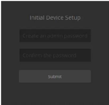
Set the admin password. If there are other tasks on the page (such as reading and accepting policies and agreements), complete them also.
Note
Be sure you have a way to remember the admin password. We cannot reset it for you. If the lost, you will need to restore factory defaults.
The full administrative interface opens when you finish.
Initial Device Set-Up Using the Vaddio Deployment Tool
Be sure you have the current version of the Vaddio Deployment Tool. This tool is available as a free download at https://info.legrandav.com/VaddioDeploymentTool. If you have a copy of the tool already, compare its version information to the version shown on the release notes. You can find this document at https://www.legrandav.com/en/products/vaddio/accessories/vaddio_deployment_tool under the Resources tab.
To complete the initial device set-up with the Vaddio Deployment Tool:
-
Download and install the Vaddio Deployment Tool if you have not done so already, then open it.
-
Power up the AV Bridge 2x1 device if you have not done so already.
-
On the Find Devices page, click Scan. If the scan does not locate the AV Bridge 2x1 device, your computer may be on a different subnet from the device. Click Advanced and specify the appropriate portion of the network to scan.
-
In the list of equipment that the scan discovers, locate the devices marked Not Set Up.

- For each device that you need to work with, click the Not Set Up button and set the admin password on the device detail page that opens.

The device shows up as unlocked after you set the admin password.
After the password is set, you will be able to log in to the administrative web interface to complete system administration and other configuration tasks.
Next Steps for New Deployments
After initial device set-up is complete, you will also need to complete system administration tasks to define how each device behaves as an element of your network.
Security settings – In each device's administrative web interface, you can configure product security features to conform to the IT policies for your environment. See Setting Passwords and Access.
Network settings – Depending on the requirements of your network, you may need to change the hostname. See Changing the Hostname. If additional network changes are required, work with the site's network specialist to configure the Luxul switch.
Do not change network settings without guidance from an on-site network specialist.
Time zone – Set the device to the appropriate time zone to ensure that timestamps in the event log are accurate. See Specifying Time Zone and NTP Server.
Room labels – Add helpful information such as the room location and phone number to the web interface of each device. See Adding Room Information to the Device's Web Interface.
Dante device identification – Locate and manage Dante devices on the network. See Identifying Dante Devices.
Setting Passwords and Access
EACH DEVICE - SECURITY PAGE
The Account Passwords and Web Server areas of the Security page provide basic security for the web interface:
- Admin password – Required for access to the admin pages of the web interface and for Telnet access to the device.
- User password – When set, allows password-protected, non-administrative access to the operator's web interface.
- Guest access – When enabled, allows non-administrative access to the operator's web interface without a password.
- Expire idle sessions – By default, the web interface automatically logs you out after 30 minutes of inactivity.

Configuring Other Security Settings
EACH DEVICE - SECURITY PAGE
Depending on your environment, you may want to make these changes:
- Enable HTTP access – When selected, administrators and operators can access the product's web interface using the less-secure HTTP protocol.
■ Enable Telnet access – When selected, the device accepts Telnet connections.
Default security-related settings:
■ HTTP access is disabled
■ Telnet access is disabled
■ Device discovery is enabled
Note
Consult your network security specialist before changing any of these settings.
- Select Show Advanced Settings. The advanced options open.

- In consultation with your network security specialist, make the desired changes.

For Non-DHCP Environments: Configuring the Device with a Static IP Address
Caution
Consult your IT department before editing network settings. Errors in network configuration can make device inaccessible from the network. Do not change DHCP/Static addressing, IP address, subnet r or gateway unless you are very familiar with the characteristics and configuration of the network install the device.
By default, the device is set to DHCP and you do not need to configure it with a static. However, if no DHCP server is available to automatically assign an address, the device will use the default IP address of 169.254.1.1. Other devices may default to the same IP address. If this is the case, you may need to follow this procedure.
If you install more than one device on a network that does not automatically assign IP addresses (a non-DHCP network), follow this procedure to prevent IP address conflicts.
Note
If the device is currently at an IP address other than 169.254.1.1, skip this section unless you instructed to configure it with a static IP address.
To access the device's Networking page during installation (skip this procedure if the device already been in service on this network):
- Connect the device according to the connection diagram, but do not connect it to the network.
- Connect the network port on the device to the network port on a computer. You may need a crossover cable.
- Open a browser and access the device's web interface at the address shown on the connected display.
- Log in as admin.

- Navigate to the Networking page.
To configure the device with a specific static IP address:
- Work with your IT department to determine the correct IP address, subnet mask, and gateway to assign.
- On the Networking page, set IP Address to Static.
- Enter the IP address, subnet mask, and gateway as directed by the IT staffer; then save your work.
The device is now ready to be connected to the network.
Changing the Device's Hostname
If your network supports hostname resolution, you may find it convenient to change the device's hostname to something easy to remember. Work with your IT department to ensure that the new hostname conforms to the organization's naming conventions.
Optional For DHCP Environments: Changing from a DHCP Address to a Static IP Address
NETWORKING PAGE
In a network that assigns IP addresses automatically, the device's IP address may change from time to time. To keep this from happening, set the IP address to Static after the device has received an IP address. Do not change the IP address, subnet mask, or gateway.
You may wish to change the IP addresses of other connected equipment to static addresses as well. For all Vaddio products with web interfaces, this setting is on the Networking page.

Adding Room Information
ROOM LABELS PAGE
Enter information about the location of the equipment and the local IT or A/V help line. This information will be displayed on all pages of the web interface.
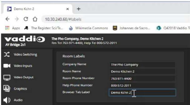
Setting System Time and Time Zone
NETWORKING PAGE
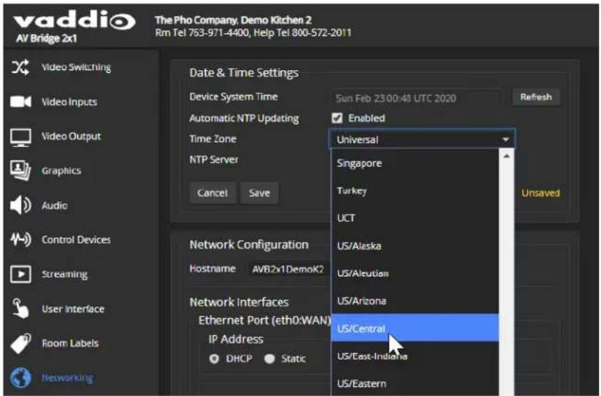
Using automatic NTP updating ensures that the timestamps in the device's diagnostic log are accurate. Specifying your time zone may make it easier to match logged events with other actions and external events.
- To make the time zone and NTP server editable, enable Automatic NTP Updating.
- Select the desired time zone from the list.
- Optional: Specify the NTP server to use. If you are not sure about this, use the default.
- Save your changes.
- To update the system time immediately, select Refresh. Otherwise, the time will update the next time the device contacts the NTP server.
Identifying Dante Devices
Use the Dante Controller application to identify the Dante devices on your subnet and optionally rename them.
Note
The Dante chip in the AV Bridge 2x1 has its own IP address and device name. These do not the AV Bridge 2x1's device name and IP address in the web interface.
To physically locate Dante devices:
-
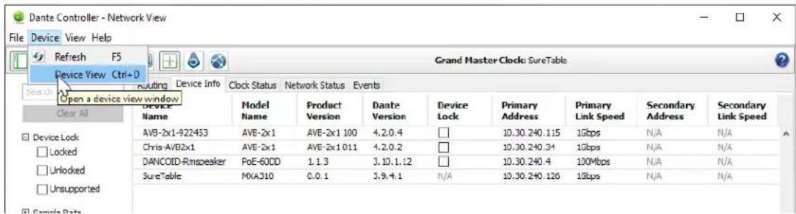
Open the Device Info tab to see the IP address and other information about each Dante device on the subnet that your computer is on.
-
From the main Network View, select Device : Device View. The Device View window opens.
Note that AV Bridge 2x1 devices will show the IP address of the Dante chip, not device's web server IP address. In the screen shot below, the device with a Dante chip at 10.30.240.115 is the same device used for the screen shots in this manual, at 10.30.240.68.
Your devices' IP addresses will probably be different from the ones in the screen shots.
- In the Device View window, select the device of interest. The window presents information about the device.

- Select the Identify icon. The way the device responds depends on the device. The AV Bridge 2x1 responds by blinking all the lights on the front panel. To stop the identifying behavior, select the Identify icon again.

To rename a device in the Dante Controller application:
In the Device View window, select the device and go to its Device Config tab. The Rename Device option is near the top of the tab.

Performance and Behavior Settings
This chapter covers performance and behavior settings for the AV Bridge 2x1.
Note
To locate or pair to Dante devices, use the Dante Controller application.
Other performance and behavior settings are in the AV Bridge 2x1 web interface.
| What do you need to do? Go to this page | |
| Adjust audio Audio | |
| Enable phantom power to microphones Audio | |
| Configure streaming Streaming | |
| Work with a connected camera Video Inputs | |
| Set up transitions between video inputs Video Switching or Video Output | |
| Set up keying Graphics | |
| Work with the PIP Video Switching or Video Output | |
| Create and edit macros (programmed sequences of actions); assign macros to triggers | Control Devices |
| Disable the Swap, PIP, and Streaming buttons on the front panel User Interface | |
| Specify which audio controls are available to the non-admin operator User Interface | |
Configuring Audio Settings
AUDIO PAGE (MULTIPLE TABS)
The web interface provides separate controls for each of the audio inputs and outputs:
- Analog – Line/Mic 1 and 2 (connections to the Audio In connectors, typically the room's microphones); Output 1 and 2 (connections to the Audio Out connectors, typically the room's speakers)
■ Dante – Up to four devices configured as audio inputs, and up to four devices configured as audio outputs - HDMI – Left and right audio channels from the two HDMI input devices, and left and right audio channels to the HDMI output.
- Streaming – Left and right audio channels for the IP stream, and for USB Playback (far-end audio) and USB Record (near-end audio).
- Matrix – Defines the source (vertical axis) for each audio output (horizontal axis). Note that USB playback cannot be the source for USB record.

Muting and Setting Volume
AUDIO PAGE – ANALOG, DANTE, HDMI, AND STREAMING TABS
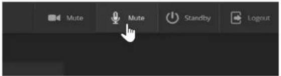
To mute all audio:
Use the microphone mute control at the top of any page.
To mute a specific audio input or output:
Go to the appropriate tab and click the icon button (microphone or speaker) associated with the input or output.

To change the volume of a specific audio input or output:
Move the volume slider associated with the input or output.
Note
Because Dante audio components connect to the network, unexpected behavior can occur. This can disruptive if the affected component is a speaker. Vaddio recommends muting Dante speakers or down their volume to the minimum setting when they are not in use.
Note
For best performance with most computers, we recommend setting the USB Record volume high.
Microphone Settings and Adjustments
AUDIO PAGE, ANALOG AND MATRIX TABS
| To accomplish this... Do this | |
| Help people to hear the person who is speaking. | Enable Speech Lift and select the microphone closest to the person who is speaking. The signal from the selected microphone goes to the speakers in the room. (Analog and Matrix tabs) |
| Automatically adjust for differences in volume as different people speak | Enable Automatic Gain Control. (Analog tab only) |
| Specify microphone priority when more one person is speaking. | Enable Chairman Override and select the microphone that has priority. (Matrix tab only) |
| Specify which audio output to use as the reference for acoustic echo cancellation | Select a Master Output/AEC Reference. (Analog and Matrix tabs) |
| Reduce hissing sounds that microphones pick up. | Enable Lowpass Filter and specify the highest frequency for the microphone to pick up. (Analog tab, per microphone) |
| Reduce low-frequency background noise (such as heating/air conditioning systems that the microphones pick up. | Enable Highpass Filter and specify the lowest frequency for the microphone to pick up. (Analog tab, per microphone) |
| Adjust the volume of specific frequency ranges to compensate for specific audio challenges. | Enable PEQ (parametric equalizer) and select Load to open the PEQ Filter window for the specified microphone. Adjust the filter settings as needed. (Analog tab, per microphone) |
Note
Use the equalizer to attenuate undesirable frequency ranges, not to boost the desirable frequencies

Enabling Phantom Power to Microphones
AUDIO PAGE, ANALOG TAB
To supply 48 VDC phantom power to a microphone connected to a Line/Mic input, check the Phantom Power checkbox below the controls for the appropriate input.

Speaker Adjustments
AUDIO PAGE, ANALOG TAB
| To accomplish this... Do this | |
| Compensate for differing speech volumes on the far end. | Select Compressor to reduce the dynamic range from the connected speakers. |
| Compensate for specific audio issues on the far end. | Use the equalizer settings for the analog outputs to attenuate specific frequency ranges. This can help if the far-end audio includes unwanted elements such as a rumbling HVAC system or a cricket in the room. |
Note
Use the equalizer to attenuate undesirable frequency ranges, not to boost the desirable frequencies

Synchronizing Audio with Video in the IP Stream
AUDIO PAGE, STREAMING TAB
If the video lags noticeably behind the audio in the IP stream, check the Delay box for the appropriate audio outputs and enter a delay value in milliseconds. The delay may differ from one output to the other.

Routing Audio
AUDIO PAGE, MATRIX TAB
The audio matrix defines where each audio output originates. Each column of the matrix shows one audio output, and each row shows one audio input. Table cells highlighted in blue mean that the input represented in that row is routed to the output represented in that column.
To specify how the AV Bridge 2x1 uses a given audio input, locate its row. Locate the column representing the desired output and select the table cell where the desired row and column intersect.
Example: In the screen shot below,
■ The left and right USB playback channels feed into all the available audio output channels. Left and right channels are separate for the HDMI output and IP stream.
■ The auto mic mixer feeds all audio inputs into the USB and IP streams.

Setting Gain Between Input and Output (Crosspoint Gain)
To adjust crosspoint gain between any input and the output to which it is routed, right-click the table cell in the matrix to open a gain control.

Configuring Streaming Settings
STREAMING PAGE
USB streaming cannot be disabled. IP streaming is disabled by default.
Supported Input Resolutions and Frame Rates
The AV Bridge 2x1 accepts the following resolutions and frame rates from the connected camera or other video input device:
■ 1920x1080p at 60, 59.94, 50, and 30 fps
■ 1920x1080i at 60, 59.94, and 50 fps
■ 1280x720p at 60, 59.94, and 50 fps
■ 1440x900 at 60 fps
■ 1280x800 at 60 fps
Configuring USB Streaming
STREAMING PAGE
To change the USB device name:
Edit the USB Device Name to change the way the AV Bridge 2x1 shows up in your soft client's device selection list.
To allow soft client control of the audio:
Check the Enabled box for HID Audio Controls to allow conferencing applications to control the audio.
Note
Most USB streaming settings are automatically negotiated with the conferencing application.

Set IP Streaming Video Settings
STREAMING PAGE
If you are not sure how to configure streaming settings, start with the Easy mode defaults. This configures most settings automatically.
To set up IP streaming in Easy quality mode:
-
Select Easy quality mode.
-
Select the desired IP streaming resolution. This determines the size of the window in which the stream is displayed.

- Easy quality mode only: Select Video Quality.
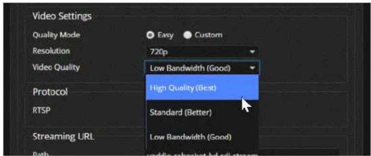
- Save your changes.
Pro Tip
If streaming video quality is poor, try a lower resolution or bandwidth.
To set up IP streaming in Custom quality mode:
-
Select Custom quality mode.
-
Select the desired resolution.

- Select the desired IP streaming frame rate.
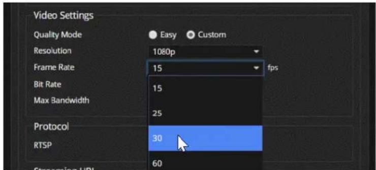
-
Select Constant or Variable bit rate.
-
Constant bit rate only: Set Max Bandwidth.

- Variable bit rate only: Set the Quality (Quantization) slider.
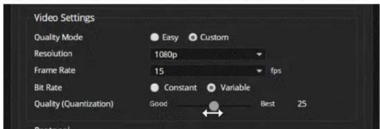
- Save your changes.
RTSP Streaming Settings
STREAMING PAGE
RTSP port: Vaddio strongly recommends using the default RTSP port number.
Path: The portion of the streaming URL that appears after the IP address. You may wish to change this to help identify the stream source – for example, demo-studio-3.
URL: The location where the stream can be viewed. This will change if you edit the path.

To view the RTSP stream:
- Open a stream viewer such as VLC Media Player.
- Select "Network stream" or your viewer's equivalent option.
- Copy the streaming URL from the device's Streaming page and paste it into the viewer as the URL for the network stream.
RTMP Streaming Settings
STREAMING PAGE
To use RTMP streaming, you must have an account with a streaming service.
Notes
When RTMP streaming is selected and a content service provider is configured, the device stream service until you stop the stream. Configure RTMP streaming before enabling it.
The RTMP stream can only be viewed from the content service provider. No local display or prn available.
To configure an RTMP streaming service:
-
Select RTMP streaming, then select Settings.
-
Expand the information box for the service.

-
Enter the name of the service.
-
Paste in the key and URL(s) provided by the service. This key is only used for sending video to the service. It is not needed to view the stream.
To select the enabled RTMP streaming service:
Expand the list of available streaming services, and select the one to use.

Enable IP streaming when you are ready to start sending content to the streaming service.
Stopping the IP Stream
STREAMING PAGE
Options:
■ To stop IP streaming entirely: Clear the Enable IP Streaming check box.
■ To stop local video and the video portion of the stream, but leave the stream running: Mute the video. Audio is available but the connected display is blank.
■ To stop the audio portion of the stream, but leave the stream running: Mute the audio. Video continues to stream, and local video is still displayed on the connected screen(s).
- To stop sending the stream to a content service provider but make it available as a network stream: Change from RTMP to RTSP streaming. Local video is still displayed on the connected screen (s).
Advanced: Changing MTU
STREAMING PAGE
The default packet size for streaming is 1400. Do not change this except in consultation with your network administrator.
Working with Video Inputs
VIDEO INPUTS PAGE
The web interface provides a control page with tabs for each camera and other video input device, allowing you to control the connected cameras without accessing their individual web interfaces. A red tally indicator identifies the tab for the current program source.
The tabs for connected Vaddio cameras present the same controls present in the cameras' own web interfaces.

Configuring the Video Output
The Video Output page provides controls to configure the video on the local HDMI output. Controls include:
■ Resolution/frame rate
- Color space
■ Video mute pattern
■ Video transition effect and time
■ Keying control and sources
■ PIP control and layout
Graphics and keying are managed on the Graphics page. See Working with Graphics.

Setting Video Transition Type and Speed
VIDEO SWITCHING PAGE OR VIDEO OUTPUT PAGE
The video transition settings determine how the video output behaves when you switch from one video input to the other.
Transition Effect and Transition Time settings are available on the Video Switching page and the Video Output page.
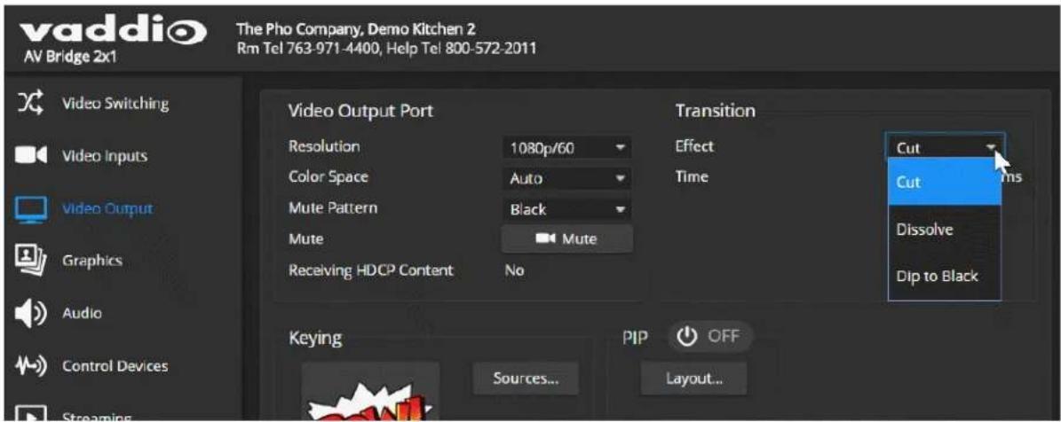
Working with Graphics
GRAPHICS PAGE, LIBRARY TAB
Use the graphics library to set up keying and placement for on-screen graphics.
To upload a graphics file:
-
Select Upload. The Upload Graphics box opens.
-
Select Choose Files and browse to the file(s). File type may be .png or .jpg.

To place the graphic on the canvas and work with it:
-
Select the expand/collapse arrow associated with the filename to open the file information.
-
Select the View icon associated with the filename. Initially the image is placed at the top left corner of the canvas (coordinates 0,0).

-
Drag the image to the desired location on the canvas, or enter the desired offset from top left.
-
Select the desired mask type - alpha, luma, chroma, or opaque.
-
After making changes, save your work and select the expand/collapse arrow to close the file information dialog box.
To manage the graphics library:
Right-click the filename to edit it.
Select the X to delete the file.
Setting up Macros and Triggers
CONTROL DEVICES PAGE
Macros may use any of the device's serial API commands. See Serial Command API.
To edit an existing macro:
Select the Edit button associated with the macro, or select the macro name. The macro opens in the Macro Editor.
To write and test a macro:
-
In the Macro Editor area, select New.
-
Give the macro a brief, descriptive name.
-
Enter the commands to perform the desired actions.
-
Save the macro.
-
Select Test to verify that the macro does what it needs to do. The Macro Execution Log displays each command as it executes, and indicates any syntax errors that may be present.
-
Make changes as needed, saving and testing until you get the desired results.
Configuring Standby Behavior
USER INTERFACE PAGE
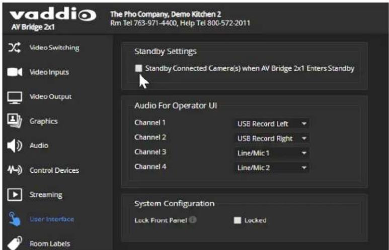
To place the cameras in standby mode along with the switcher, check the box marked "Standby Connected Cameras when AV Bridge 2x1Enters Standby."
Leave this check box unchecked if the cameras should remain powered up.
Locking the Front Panel
USER INTERFACE PAGE
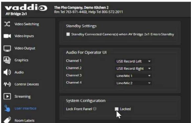
Select Lock Front Panel to disable the Swap, PIP, and Stream buttons.
The IP and Reset buttons cannot be disabled, as they may be needed if the administrator cannot access the device via the web interface or serial API.
Customizing Labels
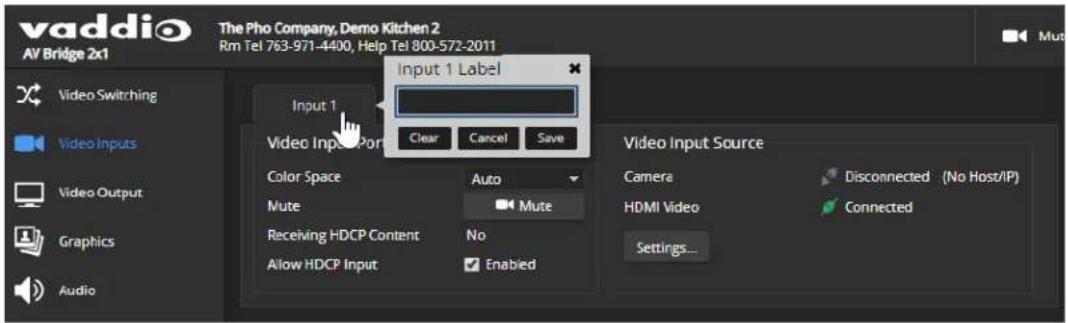
Some of the labels in the web interface are customizable – because you may find, for example, that "Podium" is a more useful label than "Line/Mic 1." You can rename:
■ Video inputs
■ Audio inputs and outputs
When in doubt, try it.
Right-click the label you want to rename. If it is customizable, it opens a dialog box.
System Maintenance
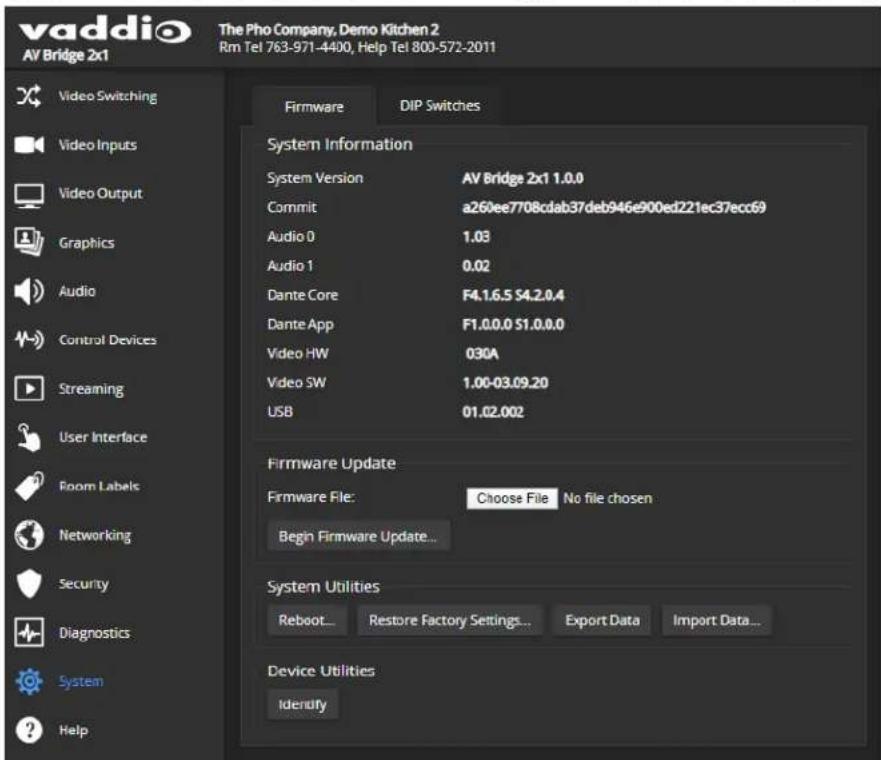
System maintenance tasks for the AV Bridge 2x1 are on the System page.
In the event that you need to contact Vaddio Technical Support, the Help page provides contact information.
Exporting and Importing Configuration Data
SYSTEM PAGE, FIRMWARE TAB
You can export a device's configuration and save it as a backup. This allows you to quickly restore customized information if you need to restore factory defaults or replace the unit, or configure additional devices the same way.
You can configure several devices the same way by configuring one device, exporting its configuration, and importing it to the other devices.
■ All the devices must be of the same model.
■ All the devices must have compatible firmware versions installed.
| What is included What is not included | |
| Room labelNTP and time zone informationAudio and video settingsStreaming settings | PasswordsHostname |
To export a configuration:
To save a copy of the current configuration, select Export Data.
The configuration exports as a .dat file and downloads to your default file download location. The filename is the device's hostname followed by the .dat file extension. If you only need to back up the configuration, you're done.
Note
This operation does not copy device-specific data such as hostname or sensitive data such as pa

To import a configuration:
- Select Import. The Import Data box opens.

- Select Choose File, and browse to the .dat file to be imported.
- Select Begin Importing Data. When the import is complete, the device reboots and you will need to log in again.
Updating the Firmware
SYSTEM PAGE, FIRMWARE TAB
From time to time, we issue new firmware to introduce new features and other product improvements, and to fix issues that turn up. We recommend keeping all your Vaddio products up to date, to get the most out of them.
Firmware updates do not typically change the configuration or password.
Note
It is rare for an update to generate errors. If this happens, please read them carefully and rec Screen shots of the error message may be very helpful in troubleshooting the problem. If the up not finish successfully, contact Vaddio technical support immediately.
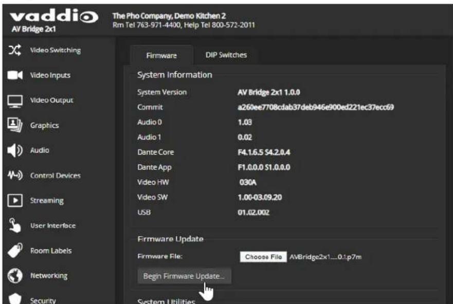
- In a separate browser tab or window, go to the appropriate product page and download the firmware update file.
- In the Firmware Update pane, select Choose File. Then browse to the update file and select it.
- Select Begin Firmware Update.
- READ the information in the Confirm dialog box and be sure you understand it.
- When you are ready to start the update, select Continue. The device reboots as the last step in the update process.
Rebooting
SYSTEM PAGE, FIRMWARE TAB
This can help if the device stops responding as you expect.
In the System Utilities section, select Reboot, then confirm. You will need to log in again after the reboot.

If rebooting the device doesn't fix the problem, you may need to restore factory defaults. Before you take that step, back up the configuration.
If the problem seems related to the device's Dante settings, you may need to correct it using the Dante Controller application.
Contacting Vaddio Technical Support
HELP PAGE
If you can't resolve an issue using your troubleshooting skills (or the Troubleshooting table in this manual), we are here to help. You'll find technical support contact information on the Help page. Each product displays a different link, to provide direct access to the product information.

Viewing Diagnostic Logs
DIAGNOSTICS PAGE
If you encounter a problem that you can't solve, your Vaddio technical support representative may ask you to download and email the log file available from the Diagnostics screen.
Note
The log may include large numbers of internal events even when no errors have occurred. Rebo generates over 100 log entries.
![vaddio AV Bridge 2x1 The Pho Company, Demo Kitchen 2 Rm Tel 763-971-4400, Help Tel 800-572-2011 Video Switching Video Inputs Video Output Graphics Audio Control Devices Streaming User Interface Room Labels Networking Security Diagnostics System Diagnostics Feb 23 03:49:30 AW2xDenk2 kernel: [ 1.001180] h264: devno is 0x3b00000, pdev id is 0 Feb 23 03:49:35 AW2xDenk2 kernel: [ 1.000660] h264: H264 Core Review 0x3b00000 Feb 23 03:49:35 AW2xDenk2 kernel: [ 1.011335] h264: Default mode is ENCODE Feb 23 03:49:35 AW2xDenk2 kernel: [ 1.015255] aze_h264s 88000000.h264_axis_core; h264: added driver successfully Feb 23 03:49:39 AW2xDenk2 kernel: [ 1.024486] inaizix i-8mm: power monitor inaizix (rsmnt = sseem vom) Feb 23 03:49:39 AW2xDenk2 kernel: [ 1.041679] inaizix i-8mm: power monitor inaizix (rsmnt = sseem vom) Feb 23 03:49:39 AW2xDenk2 kernel: [ 1.099611] inaizix i-8mm: power monitor inaizix (rsmnt = sseem vom) Feb 23 03:49:39 AW2xDenk2 kernel: [ 1.016111] inaizix i-8mm: power monitor inaizix (rsmnt = sseem vom) Feb 23 03:49:39 AW2xDenk2 kernel: [ 1.053607] sdnc1: secure digital host controller Interface driver Feb 23 03:49:39 AW2xDenk2 kernel: [ 1.070887] sdnc1: Copyright(<) Pierre Ossman Feb 23 03:49:39 AW2xDenk2 kernel: [ 1.054151] sdnc1-plete SDNCI platform and OF driver helper Feb 23 03:49:39 AW2xDenk2 kernel: [ 1.127211] mcc0: SDNCI controller on a0100000.mmc [e0100000.mmc using /DMV Feb 23 03:49:39 AW2xDenk2 kernel: [ 1.138635] lodtrig-cpu: registered to indicate activity on CPUs Feb 23 03:49:39 AW2xDenk2 kernel: [ 1.140763] nf.cnntrack version 0.5.0 (11264 buckets, 45066 max) Feb 23 03:49:39 AW2xDenk2 kernel: [ 1.156182] io_tables: (C) 2006-2006 Netfiller Core Tom Feb 23 03:49:39 AW2xDenk2 kernel: [ 1.163851] initializing XPRM netlink socket Feb 23 03:49:39 AW2xDenk2 kernel: [ 1.166133] NET: Registered protocol family t7 Feb 23 03:49:39 AW2xDenk2 kernel: [ 1.176618] BDCQ DRX.1g ULAB Support v1.8 Feb 23 03:49:39 AW2xDenk2 kernel: [ 1.178915] registering sum/sqm emulation handler Feb 23 03:49:39 AW2xDenk2 kernel: [ 1.178612] mcc0: new high speed so card at address over Feb 23 03:49:39 AW2xDenk2 kernel: [ 1.178613] mmcbid: mcc0!000? bDCQ NSA MIB Feb 23 03:49:39 AW2xDenk2 kernel: [ 1.188927] mccbluxp: pi p2 pi p4 < ps p6 p7 pi p9 >. Feb 23 03:49:39 AW2xDenk2 kernel: [ 1.215335] input: gpio_keys as /devices/socq/gpio_keys/input/input/ Feb 23 03:49:39 AW2xDenk2 kernel: [ 1.225557] ALSA device list: Feb 23 03:49:39 AW2xDenk2 kernel: [ 1.255331] #6: xylan-logi15s 0 Feb 23 03:49:39 AW2xDenk2 kernel: [ 1.233288] Freeing unused kernel memory; AOSK Feb 23 03:49:35 AW2xDenk2 kernel: [ 1.856759] f7f00086.serial: ttywnB at MTD Ox3f7l0000 (irq = 57, base_boud = 388125) is a mr_sart Feb 23 03:49:35 AW2xDenk2 kernel: [ 1.868816] f7f00086.serial: ttywnB at MTD Ox3f7l0000 (irq = 57, base_boud = 588175) is a mr_sart Download Refresh Clear Restore Auto-Refresh](/content/2026/05/883573/images/7a1e567d01fedbc451419a7216b28a1c54efb1970a50b8681de360f584863f51.jpg)
Operating the AV Bridge 2x1
The AV Bridge 2x1 provides a web-based user interface in addition to the front panel controls for basic functions. To access the web interface, you may need to log in with the user account credentials, depending on how the device is configured. The admin login is not required.
Contact the administrator for information on accessing and logging in to the web interface.
To operate the device effectively, you will need to be able to view one of these:
■ HDMI output (the display connected to the device)
USB stream
IP stream
About Viewing Streams
You will need additional information and software to view the IP and USB streams from the AV Bridge 2x1.
To view the IP stream:
■ The device must be configured to enable IP streaming.
- You will need to know the streaming URL for the IP stream. Contact the system administrator for this information. It is available from Streaming page in the admin portion of the web interface.
■ You will need a stream viewer application such as VLC Media Player.
To view the USB stream:
Connect your computer to the USB port on the AV Bridge 2x1, and do one of these things:
■ Open a stream viewer and select the camera as the video capture device.
■ Start or join a conference.
USB streaming is always enabled.
When viewing either stream, keep in mind that there is always inherent latency and network-dependent latency, so the video and audio may not be synchronized. An audio delay adjustment is available to administrators on the Audio page of the web interface. See Speaker Adjustments.
Muting and Video: Quick Steps You Can Take from Any Page
All non-administrative pages of the web interface provide controls to do these things:
- Mute all video – HDMI Out and the USB and IP streams send the selected video mute pattern, either black video or color bars. Audio remains on unless you mute it also.
- Mute all audio – Disables the microphone inputs and the audio portion of the stream. It does not disable PC audio input or HDMI audio output; if you mute audio while playing content from a PC, the audio portion of the content is not muted. Video remains on unless you mute it also.
- Change video input (Switching) – Toggle between input 1 and input 2.
- Turn keying on/off and select keying source – When you change the video input, you may want to change keying as well.
- Turn the PIP on/off and select PIP layout – Tailor the PIP behavior to what you need right now.
- Set the system to standby mode – Connected cameras may also go to standby mode, depending on how the system is configured.

Working with Cameras
The web interface shows the active video source in red.
Select the video source to display on the HDMI output and the IP and USB streams. If it is a camera, you do not need to log in to its web interface - you can control it directly from the AV Bridge 2x1 web interface. The Home page and Camera page both present the camera controls available. These depend on the camera's capabilities.
Working with Camera Presets
HOME PAGE (USER OR GUEST ACCESS)
If presets have been defined for the selected video input, they are available on the Home page. The administrator has the option to customize the labels for the video inputs and the presets for each.

Controlling Movement
CAMERA PAGE (USER OR GUEST ACCESS)
The Camera page presents the same controls that are available from the selected video input's web interface. Depending on the camera, these may include pan, tilt, zoom, and focus controls.

Working with Audio
AUDIO PAGE (USER OR GUEST ACCESS)
Up to four audio channels may be available on the operator's Audio page. Each provides a mute/unmute button, volume read-out, and volume slider control.
The system administrator selects the audio channels available on this page.

Working with Macros
MACROS PAGE (USER OR GUEST ACCESS)
Macros provide shortcuts for common sequences of actions. For example, the system administrator might create a macro that moves and zooms a camera to frame the presenter at the podium, then switches to that camera and the podium microphone.
If macros have been defined, you can select them from the Macros page.

Going to Standby (Low Power) Mode
ALL PAGES
The standby control is available at the top of each page of the web interface.
When the system is in standby, no audio or video is sent or received and most of the web interface controls are unavailable.
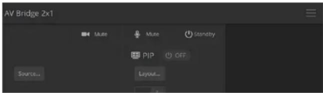
Depending on how the device is configured, connected cameras may also go to standby mode. See Configuring Standby Behavior.
Serial Command API
The Vaddio serial command API allows an external device such as an AMX or Crestron presentation system to control the device. It is also used for device macros. The serial command API can be accessed via Telnet or direct RS-232 connection. Commands are the same using either communication protocol.
Note
At the start of the session, you must log in using the admin account.
Network connection: Telnet connections use port 23. Windows provides a built-in Telnet client; PuTTY can also be used.
Usage notes:
■ The > character is the command prompt.
- Using a question mark as a command or command parameter will bring up a list of available commands, subcommands, or command parameters. For example, ? returns all top-level commands; system ? returns the valid subcommands for the system command; and system reboot ? returns the parameter available for the system reboot command.
■ CTRL-5 clears the current serial buffer on the device.
Typographical conventions:
■ {x | y | z} - Choose x, y, or z.
-
- < x..y > - A value in the range of x through y is required.
■ [optional] – This parameter (such as [speed]) is not required.
For information about the RS-232 serial interface, see RS-232 Serial Communication Settings and Port
Pin-out.
audio volume
Gets or sets the volume of the specified audio channel. The valid range depends on the channel.
| Synopsis audio [ channel ] volume {get | up | down | set } | ||
| Channels | master | The channel currently designated as master/AEC reference. |
| line_in_1line_in_2 | Line In 1 and 2 (microphones or other inputs) | |
| usb3_playback_leftusb3_playback_right | USB3 Playback left and right input channels | |
| hdmi_in_<1..2>_lefthdmi_in_<1..2>_right | HDMI inputs 1 and 2, left and right channels | |
| dante_in_<1..4> | Dante audio inputs 1 through 4 (microphones) | |
| line_out_1line_out_2 | Line Out 1 and 2 (speakers or other outputs) | |
| usb3_record_leftusb3_record_right | USB3 Record left and right output channel | |
| ip_out_leftip_out_right | Left and right channels of the IP stream's audio | |
| hdmi_out_lefthdmi_out_right | Left and right channels of the HDMI audio output. | |
| dante_out_<1..4> | Dante audio outputs 1 through 4 (speakers) | |
| Options | get | Returns the current volume of the specified channel. |
| up | Increases the volume of the specified channel by 1 dB. | |
| down | Reduces the volume of the specified channel by 1 dB. | |
| set | Sets the volume of the specified channel in dB. Valid ranges: | |
| Examples | audio line_in_1 volume upOK>Increases the volume for Line In 1 by 1 dB.audio line_out_1 volume getvolume -10.0 dBOK>Returns the current volume for the speaker connected to the line out port. | |
audio mute
Gets or sets the mute status of the specified audio channel.
| Synopsis audio <channel> mute {get | on | off | toggle} | ||
| Channels | master | The channel currently designated as master/AEC reference. |
| line_in_1line_in_2 | Line In 1 and 2 (microphones or other inputs) | |
| usb3_playback_leftusb3_playback_right | USB3 Playback left and right input channels | |
| hdmi_in_<1..2>_lefthdmi_in_<1..2>_right | HDMI inputs 1 and 2, left and right channels | |
| dante_in_<1..4> | Dante audio inputs 1 through 4 (microphones) | |
| line_out_1line_out_2 | Line Out 1 and 2 (speakers or other outputs) | |
| usb3_record_leftusb3_record_right | USB3 Record left and right output channel | |
| ip_out_leftip_out_right | Left and right channels of the IP stream's audio. | |
| hdmi_out_lefthdmi_out_right | Left and right channels of the HDMI audio output. | |
| dante_out_<1..4> | Dante audio outputs 1 through 4 (speakers) | |
| Options | get | Returns the current mute state of the specified channel. |
| on | Mutes the audio for the specified channel. | |
| off | Unmutes the audio for the specified channel. | |
| toggle | Changes the mute state for the specified channel – unmutes if it was muted, mutes if it was not. | |
| Examples | >audio master mute getmute: offOK>Returns the current mute state of master mute. It is off, so audio is not globally muted. Some audio channels may be muted, however.>audio line_out_1 mute onOK>Mutes the Line Out 1 port. | |
audio route
Gets or sets the input routed to the specified output.
| Synopsis audioroute {get | set} | ||
| Outputs | line_out_1line_out_2 | Line Out 1 and 2 (speakers or other outputs) |
| usb3_record_leftusb3_record_right | USB3 Record left and right output channel. Not permitted to have USB3 Playback Left/Right in its route list. | |
| ip_out_leftip_out_right | Left and right channels of the IP stream's audio. | |
| hdmi_out_lefthdmi_out_right | Left and right channels of the HDMI audio output. | |
| dante_out_<1..4> | Dante audio outputs 1 through 4 (speakers) | |
| Inputs | line_in_1line_in_2 | Line In 1 and 2 (microphones or other inputs) |
| usb3_playback_leftusb3_playback_right | USB3 Playback left and right input channels. Not permitted to be routed to USB Record. | |
| hdmi_in_<1..2>_lefthdmi_in_<1..2>_right | HDMI inputs 1 and 2, left and right channels | |
| dante_in_<1..4> | Dante audio inputs 1 through 4 (microphones) | |
| Options | get | Returns the routing for the specified output. |
| set | Sets the routing for the specified output. | |
| Examples | >audio usb3_record_left route get[auto_mic_mix]OK>Returns the current source of the left channel of USB3 Record. The auto mic mixer is currently routed to the left channel of the USB3 Record output.>audio ip_out_right route set line_in_1Routes Line Input 1 to the right channel of the outbound IP stream. | |
audio crosspoint-gain
Returns or sets the input routing gain, in dB, for a given output and input.
| Synopsis audio <output> crosspoint-gain {get | set} | ||
| Outputs | line_out_1line_out_2 | Line Out 1 and 2 (speakers or other outputs) |
| usb3_record_leftusb3_record_right | USB3 Record left and right output channel | |
| ip_out_leftip_out_right | Left and right channels of the IP stream's | |
| hdmi_out_lefthdmi_out_right | Left and right channels of the HDMI audio output. | |
| dante_out_<1..4> | Dante audio outputs 1 through 4 (speakers) | |
| Inputs | line_in_1line_in_2 | Line In 1 and 2 (microphones or other inputs) |
| usb3_playback_leftusb3_playback_right | USB3 Playback left and right input channels | |
| hdmi_in_<1..2>_lefthdmi_in_<1..2>_right | HDMI inputs 1 and 2, left and right channels | |
| dante_in_<1..4> | Dante audio inputs 1 through 4 (microphones) | |
| Options | get | Returns the routing gain from the specified input to the specified output. |
| set<-12.00..12.00> | Sets the routing gain from the specified input to the specified output. Valid range is -12.00 dB to 12.00 dB. | |
| Examples | >audio line_out_1 crosspoint-gain hdmi_in_left get3.95OK>Returns the current gain setting of the crosspoint between Line Output 1 and HDMI Input Left in dB.>audio usb3_record_left crosspoint-gain line_in_1 set 6.00OK>Sets the crosspoint gain of USB Record Left and Line In 1 to 6 dB. | |
streaming settings get
Returns current IP and USB streaming settings.
| Synopsis streaming settings get | ||
| Parameters | IP Custom_Frame_Rate | Frame rate selected in Custom mode. |
| IP Custom_Resolution | Resolution selected in Custom mode. | |
| IP Enabled | May be true or false. Specifies whether IP streaming is enabled. | |
| IP MTU | MTU for IP streaming. Default is 1400. | |
| IP Port | The RTSP port number used for IP streaming. Default is 554. | |
| IP Preset_Quality | Video quality selected in Easy mode. | |
| IP Preset_Resolution | Resolution selected in Easy mode. | |
| IP Protocol | The IP streaming protocol in use (RTSP or RTMP). | |
| IP URL | The URL where the stream is available. | |
| IP Video_Mode | Video quality mode selected (preset or custom). | |
| USB Active | Specifies whether USB streaming is active (in a conference). | |
| USB Device | The USB device name. | |
| USB Frame_Rate | The current frame rate for the USB stream. If the USB stream is not active, the frame rate is 0. | |
| USB Resolution | The current resolution for the USB stream. If the USB stream is not active, the resolution is 0x0. | |
| USB Version | The USB version in use (USB 3). | |
| Example | IP Custom_Frame_Rate 30IP Custom_Resolution 720pIP Enabled trueIP MTU 1400IP Port 554IP Preset_Quality High Quality (Best)IP Preset_Resolution 1080pIP Protocol RTSPIP URL vaddio-av-bridge-2x1-streamIP Video_Mode presetUSB Active trueUSB Device AV Bridge 2x1USB Frame_Rate 30USB Resolution 1080pUSB Version 3OK> | |
streaming ip enable
Set or change the state of IP streaming.
| Synopsis streaming ip enable {get | on | off | toggle} | ||
| Parameters | get | Returns the current state of IP streaming |
| on | Enables IP streaming. | |
| off | Disables IP streaming. | |
| toggle | Changes the state of IP streaming (on if it was off, or off if it was on).streaming ip enable toggle has the same effect as selecting the Enable IP Streaming checkbox in the web interface. | |
| Example | >streaming ip enable on>OKEnables IP streaming.>streaming ip enable getenabled: true>OKReturns the current state of IP streaming. | |
camera home
Moves the specified camera to its home position.
| Synopsis camera | <1..2> home | |
| Required <1..2> $pecify the camera to control. | ||
| Example | camera 1 homeMoves camera 1 to its home position. | |
camera pan
Moves the specified camera horizontally
| Synopsis camera | <1..2> pan { left [] | right [] | stop } | |
| Required <1..2> $pecify the camera to control. | ||
| Options | left | Moves the camera left. |
| right | Moves the camera right. | |
| stop | Stops the camera's horizontal movement. | |
| speed <1..24> Optional: integer | 1 - 24 specifies the speed for right or left movement.Default speed is 12. | |
| Examples | camera 2 pan leftPans camera 2 left at the default speed. | |
| camera 2 pan right 20Pans camera 2 right using a speed of 20. | ||
| camera 1 pan stopStops camera 1's horizontal motion. | ||
camera tilt
Moves the specified camera vertically.
| Synopsis camera | <1..2> tilt { up [] | down [] | stop } | |
| Required <1..2> $pecify the camera to control. | ||
| Options | up | Moves the camera up. |
| down | Moves the camera down. | |
| stop | Stops the camera's vertical movement. | |
| speed <1..20> Optional: integer | 1 - 20 specifies the speed for up or down movement. Default speed is 10 | |
| Examples | camera 1 tilt upTilts camera 1 up at the default speed. | |
| camera 2 tilt down 20Tilts camera 2 down using a speed of 20. | ||
| camera 1 tilt stopStops camera 1's vertical motion. | ||
camera zoom
Moves the specified camera in toward the subject or out away from the subject.
| Synopsis camera | <1..2> zoom { in [] | out [] | stop } | |
| Required <1..2> | Specify the camera to control. | |
| Options | in | Zooms the camera in. |
| out | Zooms the camera out. | |
| stop | Stops the camera's zoom movement. | |
| Optional - integer 1 – | 7 specifies the speed forzoom movement. Default speed is 3. | |
| Examples | camera 1 zoom inZooms camera 1 in at the default speed. | |
| camera 2 zoom out 7Zooms camera 2 out using a speed of 7. | ||
| camera 2 zoom stopStops camera 2's zoom motion. | ||
camera preset
Moves the camera to the specified preset, or stores the current camera position and optionally CCU information, either with or without specifying that Tri-Synchronous Motion is to be used when moving to this position.
| Synopsis camera | <1..2> preset { recall | store} <1..16> [tri-sync <1..24>] [save-ccu] | |
| Required <1..2> | $pecify the camera to control. | |
| Options recall | <1..16> Moves the camera to the specified preset,using Tri-Synchronous Motion if this was saved with the preset. If CCU information was saved with the preset, the camera switches to the CCU setting associated with the preset. | |
| store <1..16> Stores the current camera position as the specified preset. | ||
| tri-sync <1..24> Optional: Specifies that the camera uses Tri-Synchronous Motion to move to this position, using the specified speed. Valid only for cameras that have the Tri-Synchronous Motion feature. | ||
| save-ccu | Optional: Saves the current CCU settings as part of the preset. If not specified, the last color settings are used when recalled. | |
| Examples | >camera 2 preset recall 3OK>Moves camera 2 to its stored preset 3.>camera 2 preset store 1CK>Saves camera 2's current position as its preset 1.>camera 2 preset store 4 tri-sync 15CK>Stores camera 2's current position as preset 4. The camera will use Tri-Synchronous Motion at speed 15 when it is recalled to this preset.>camera 2 preset store 2 tri-sync 10 save-ccuCK>Stores camera 2's current position as preset 2. The camera applies the current CCU settings and uses Tri-Synchronous Motion at speed 10 when it is recalled to this preset. | |
camera ccu get
Returns or sets CCU (lighting) information for the specified camera.
Options | auto_white_balance | Current state of the auto white balance setting (on or off). |
| red_gain | Red gain value as an integer (0 to 255). | |
| blue_gain | Bue gain value as an integer (0 to 255). | |
| backlight_compensation | Current state of the backlight compensation setting (on or off). | |
| iris | Returns the iris value as an integer (0 to 11). | |
| auto_iris | Returns the current auto-iris state (on or off). | |
| gain | Returns the gain value as an integer (0 to 11). | |
| detail | Returns the detail value as an integer (0 to 15). | |
| chroma | Returns the chroma value as an integer (0 to 14). | |
| wide_dynamic_range | Returns the current state for Wide Dynamic Range (on or off). Returns null if the camera does not support this feature. | |
| all | Returns all current CCU settings. | |
| Examples | >camera 3 ccu get irisiris 6OK>Returns the current iris value.>camera 3 ccu get red_gainred_gain 201OK>Returns the current red gain value.>camera 3 ccu get allauto_iris onauto_white_balance onbacklight_compensation offblue_gain 193chroma 2detail 8gain 3iris 11red_gain 201wide_dynamic_range offOK>Returns all current CCU settings. | |
camera ccu set
Sets the specified CCU (lighting) information.
| Synopsis camera | <1..2> ccu set | |
| Required <1..2> S | Specify the camera to control. | |
Options auto_white | ite_balance {on | off} Auto white balance setting (on or off). Auto white balance overrides red gain and blue manual settings. | |
| red_gain <0..255> Red gain value (integer 0 to 255). Can only be used when auto white balance is off. | ||
| blue_gain <0..255> Blue gain value (integer 0 to 255). Can only be used when auto white balance is off. | ||
| backlight_compensation {on | off} Backlight compensation setting (on or off). Can only be used when wide dynamic range mode is off. | ||
| iris <0..11> Iris value (integer 0 to 11). Can only be used when auto-iris is off. | ||
| auto_iris {on | off} Auto-iris state (on or off). Disables manual iris and gain when it is on. | ||
| gain <0..11> Gain value (integer 0 to 11). Can only be used when auto-iris is off. | ||
| detail <0..15> Detail value (integer 0 to 15). | ||
| chroma <0..14> Chroma value (integer 0 to 14). | ||
| wide_dynamic_range {on | off} Wide Dynamic Range (on or off). Can only be used when backlight compensation is off. | ||
| Examples | >camera 2 ccu set auto_iris offOK>Turns off auto-iris mode for camera 2, returning the camera to manual iris control.>camera 2 ccu set red_gain 10OK>Sets camera 2's red gain value to 10. | |
camera ccu scene
Stores the current CCU scene to the specified camera, or recalls the specified ccu scene for the specified camera. Valid only if the specified camera supports CCU scenes.
| Synopsis camera | <1..2> ccu scene {recall {factory <1..6> | custom <1..3>} | store custom <1..3>} | |
| Required <1..2> | Specify the camera to control. | |
| Options recall | factory <1..6>recall custom <1..3> | Recalls the camera to the specified scene (factory 1 - 6 or custom 1 - 3). |
| store custom <1..3> Saves the current scene as the specified custom scene. | ||
| Examples | >camera 2 ccu scene recall factory 2OK>Sets camera 2 to use factory CCU scene 2.>camera 2 ccu scene store custom 1OK>Saves the current CCU scene to camera 2 as its custom CCU scene 1. | |
camera focus
Changes the camera focus.
| Synopsis camera | <1..2> focus {{ near [] | far []} | {mode [auto | manual | get]} | stop } | |
| Required <1..2> S | specify the camera to control. | |
| Options | near | Brings the focus nearer to the cameraCan only be used when camera is in manual mode |
| far | Moves the focus farther from the cameraCan only be used when camera is in manual mode. | |
| speed [1..8] Optional: integer 1 | - 8 specifies the speed for changing focus | |
| stop | Stops the camera's focus movement | |
| mode [auto | manual | get] | Specifies automatic or manual focus mode, or returns the current focus mode. | |
Examples | camera 3 focus nearOK>Brings the focus near at the default speed.camera 3 focus far 7OK>Moves the focus farther from the camera at a speed of 7.camera 3 focus mode getauto_focus: onOK>Returns the current focus mode. | |
camera comm host
Directory operations – get the IP address of the device at the specified input, add or delete a device.
| Synopsis camera | comm host {get | set| unset} | |
| OptionsInteger 1 to 4; specifies which input to manage. | ||
| get | Returns the IP address of the device at this input. | |
| setSet this input to the IP address or hostname of an input device. Equivalent to adding a device to the directory using the web interface. | ||
| unset | Delete the IP address information for the specified input. Equivalent to deleting a device from the directory using the web interface. | |
| Examples>camera 1 comm host gethost: 10.30.240.160 (connected)OK> | ||
camera standby
Set or change standby status for the specified camera.
| Synopsis camera | <1..2> standby { off | on | toggle | get} | |
| Required | <1..2> | Specify the camera to control. |
| Options | off | Brings the camera out of standby mode. |
| on | Stops video and puts the camera in standby mode. | |
| toggle | Changes the camera's standby state - if it was not in standby mode, it enters standby; if it was in standby mode, it "wakes up." | |
| get | Returns the camera's current standby state. | |
| Examples | camera 1 standby offBrings camera 1 out of standby mode.camera 2 standby onPuts camera 2 in standby mode.camera 2 standby getReturns the standby status of camera 2 in a form like this:standby: offOK> | |
video program pip
Get or set the state of the PIP.
When not in a call, the PIP source is the HDMI input that is not currently selected; the main image is from the selected input.
In a call, the PIP is near-end video (the selected HDMI input); the main image is far-end video.
| Synopsis video program pip {get | on | off | toggle | layout} | ||
| Options | get | Returns the current source of the PIP. |
| on | Enables the PIP. | |
| off | Disables the PIP. | |
| toggle | Changes the state of the PIP. | |
| layoutupper_rightlower_rightlower_leftupper_lefttop_bottomleft_right | Specifies the screen lay-out. The PIP may in any corner of the screen, or the screen be split vertically or horizontally. | |
| Examples | video program pip getsource: input2OK>Returns the source of the PIP.video program pip layout left_rightOK>Sets the video output to show side-by-side images of the video output and PIP. | |
video mute
Gets or sets the video mute status of the specified channel. When video is muted, the device sends a mute pattern such as blue or black video with an on-screen message stating that video mute is on. This can be desirable when preparing the room or when privacy is needed.
| Synopsis videomute {get | off | on | toggle} | ||
| Channels | master | All video channels. |
| input1 | Video from HDMI input 1. | |
| input2 | Video from HDMI input 2. | |
| Options | get | Returns the current video mute status. |
| off | Unmutes the video. (Normal video resumes.) | |
| on | Mutes the video. (Black screen with message) | |
| toggle Changes the video mute status. | ||
| Examples | video input1 mute onMutes video from HDMI input 1.video master mute getmute: offOK>Video is not globally muted. Note that individual video channels may be muted, however. If the two commands above were issued in the sequence shown, the audio from Input 1 would be muted although video is not globally muted. | |
video type
Gets or sets the video type (camera or other video source) of the specified channel.
| Synopsis videotype { get | set} | ||
| Channels | input1 | Video from HDMI input 1. |
| input2 | Video from HDMI input 2. | |
| Options | get | Returns the video type (camera or video) of the specified input. |
| set | Specifies the current video type (camera or video) of the specified input; for use when the AV Bridge 2x1 does not automatically detect what type of device is connected. | |
| video | Identifies the input as a non-camera video source. | |
| camera Identifies the input as a camera. | ||
| Example | video input1 type getinput type: cameraOK>The device connected to Input 1 is a camera. | |
trigger
Turn an existing trigger on or off. This command has no effect if the specified trigger has not been defined.
Note
If the web interface's macro/trigger test mode is in use, this command is disabled.
| Synopsis trigger <1..10> {off | on | block} | ||
| Required <1..10> | The trigger index (identifier) - triggers 1 through 10 are available. | |
| {off | on} | Set the state of the trigger. | |
| Optional | block | Block execution of subsequent command to allow macros to finish executing (similar to sleep). The default time to block is 60 seconds. |
| <seconds> Number of seconds to block. | ||
| Example trigger | 3 onTurns trigger 3 on.trigger 1 off block 10Turns off trigger 1, and blocks for up to 10 seconds while any macros in progress finish. | |
network ping
Sends an ICMP ECHO_REQUEST to the specified IP address or hostname.
| Synopsis network | ping [count] [size] | |
| Options | The number of ECHO_REQUEST packets to send. Default is five packets. | |
| The size of each ECHO_REQUEST packet. Default is 56 bytes. | ||
| The IP address where the ECHO_REQUEST packets will be sent. | ||
| Examples | >network ping 192.168.1.66PING 192.168.1.66 (192.168.1.66): 56 data bytes64 bytes from 192.168.1.66: seq=0 ttl=64 time=0.476 ms64 bytes from 192.168.1.66: seq=1 ttl=64 time=0.416 ms64 bytes from 192.168.1.66: seq=2 ttl=64 time=0.410 ms64 bytes from 192.168.1.66: seq=3 ttl=64 time=0.410 ms64 bytes from 192.168.1.66: seq=4 ttl=64 time=3.112 ms--- 192.168.1.66 ping statistics ---5 packets transmitted, 5 packets received, 0% packet lossround-trip min/avg/max = 0.410/0.964/3.112 ms>Sends five ECHO_REQUEST packets of 56 bytes each to the host at 192.168.1.66. | |
| >network ping count 10 size 100 192.168.1.1Sends 10 ECHO_REQUEST packets of 100 bytes each to the host at 192.168.1.1.The command returns data in the same form as above. | ||
network settings get
Returns the device's current network settings, including MAC addres, IP address, netmask, and gateway.
| Synopsis network | settings get |
| Example network | settings getName: eth0:WANMAC Address: 00:04:a3:85:0a:eeIP Address: 10.30.240.187Netmask: 255.255.255.0VLAN: DisabledGateway: 10.30.240.254Hostname: bergstromOK> |
system standby
Gets, sets, or toggles the camera controller's current standby status.
Cameras currently connected to the video inputs may also go to standby when you set system standby on. This depends on how the device is configured.
| Synopsis | system standby {get | on| off | toggle} | |
| Options | get | Returns the device's current standby status. |
| on | Sets the device to standby mode. | |
| off | Brings the device out of standby mode. | |
| toggle | Changes the device's standby status. | |
| Examples | system standby getReturns the factory reset status in this form:standby: off(the device is not in standby mode.) | |
| system standby onImmediately sets the device to standby mode. | ||
system reboot
Reboots the system either immediately or after the specified delay. Note that a reboot is required when resetting the system to factory defaults (system factory-reset).
| Synopsis | system reboot [] | |
| Options | The number of seconds to delay the reboot. | |
| Examples | >system rebootOK>The system is going down for reboot NOW! avb2x1-D8-80-39-62-A7-C5Reboots the system immediately.>system reboot 30Reboots the system in 30 seconds. The response is in the same form; the system message appears at the end of the delay. | |
system factory-reset
Gets or sets the factory reset status. When the factory reset status is on, the system resets to factory defaults on reboot.
Note
Factory reset does not affect settings managed in the Dante Controller application.
| Synopsis system | factory-reset {get | on | off} | |
| Options | get | Returns the device's current factory reset status. |
| on | Enables factory reset on reboot. | |
| off | Disables factory reset on reboot. | |
| Examples | >system factory-reset getfactory-reset (software): offfactory-reset (hardware): offOK>Returns the factory reset status.This evaluates the most recent system factory-reset on or off command, if one has been received, then reads the rear panel DIP switches and returns the status on if they are all in the down position.>system factory-reset onfactory-reset (software): onfactory-reset (hardware): offOK>Enables factory reset upon reboot.NoteThis command does not initiate a factory reset. The factory reset takes place on next reboot. | |
version
Returns the current firmware version.
| Synopsis version | |
| Example | versionReturns current firmware version information in a form something like this: |
history
Returns the most recently issued commands from the current Telnet session. Since many of the programs read user input a line at a time, the command history is used to keep track of these lines and recall historic information.
| Synopsis history | ||
| OptionsInteger value | specifying the maximum | number of commands to return. |
| Examples | historyDisplays the current command buffer. | |
| history 5Sets the history command buffer to remember the last 5 unique entries. | ||
| Additional information You | can navigate the command history using the up and down arrow keys.This command supports the expansion functionality from which previous commands can be recalled from within a single session. History expansion is performed immediately after a complete line is read.Examples of history expansion:* !! Substitute the last command line.* !4 Substitute the 4th command line (absolute as per 'history' command)* !-3 Substitute the command line entered 3 lines before (relative) | |
 | ||
help
Displays an overview of the CLI syntax.
| Synopsis help | |
Example | help |
Note
Use ? as a command parameter to see information about a given command's syntax.
exit
Ends the command session. If the session is via Telnet, the Telnet socket closes as the session ends. If the session is via RS-232 serial connection, the session ends and a new session automatically opens.
| Synopsis exit | |
| Example | exit |
Specifications
| USB Stream Video and audio; up to 1080p/60 resolution (Full HD) | |||
| IP Stream RTSP or RTMP video and audio; up to 1080p/30 resolution | |||
| HDMI Inputs Two HDMI inputs, video and audio; up to1080p/60 Resolution (Full HD) | HDMI Output Video and audio; up to1080p/60 Resolution (Full HD) | ||
| Audio Inputs Stereo USB Stereo HDMI Two balanced mic/line-level inputs Dante-compatible | Audio Outputs Stereo USB AAC IP audio stream Two balanced line-level outputs Dante-compatible | ||
| Control Browser-based user interface for configuration and administration; front panel controls for IP address toggle, power reset, and factory reset; Telnet a 232 for external control | |||
| Input Power PoE+ Phantom Power to Microphones | 48 VDC, 10 mA | ||
| Height | 1.72 in. (4.4 cm) | Width | 8.38 in. (21.3 cm) |
| Depth | 6.0 in. (15.2 cm) | Weight | 2.65 lb. (1.2 kg, or 127 plain M&M candies) |
| Temperature | Operating and Storage: 32° to 104° F (0° to 40° C) | ||
| Humidity | Operating and Storage: 20% to 80% RH non-condensing | ||
Troubleshooting and Care
If the equipment does not power up as expected, use this table to determine whether to call Vaddio Technical Support.
Note
If the equipment behaves in a way that suggests even a remote possibility of a bad cable, ple known good cable with the same pin-out. Factory-made cables can be defective. Cables can appe good but only work part of the time. A cable may pass a standard continuity check but be ur enough power to the connected device.
Crimping tools can crimp unevenly, contacts can break internally, and individual conductors in the can break inside the jacketing material. Any of these can result in a cable that passes a conti but does not work reliably.
(The author would like to confess having made more than a few almost-good cables. It happens.)
Power Issues
| What is it doing? Possible causes Check and correct | ||
Nothing. The buttons do not light up. | Power is not connected. Check the connections from the wall outlet to the PoE+ power injector and from the power injector to the device. | |
| The wall outlet is not active (Check by finding out if it powers something else, such as a laptop or phone charger.) | Use a different outlet. | |
| The device or its power injec is bad. | Contact your reseller or Vaddio Technical Support. | |
| Unresponsive camera (no video, unable to control the camera, or both) | A cable is connected to the wrong port. | Check and correct cable connections. |
| A cable is bad. (This can ev be a problem with factory cables.) | Check using a known good cable with the same pin-out. | |
| There is a problem with the camera. | Refer to the troubleshooting information in the camera manual. | |
Control Issues
| What is it doing? Possible causes Check and correct | ||
| Swap button does not do anything. | The front panel is locked. | This is normal.Change the selected input from the web interface or unlock the front panel (User Interface page). |
| PIP button does not do anything. | The front panel is locked. | This is normal.Change the selected input from the web interface or unlock the front panel (User Interface page). |
| Stream button does not do anything. | The front panel is locked. | This is normal.Unlock the front panel (User Interface page). |
| The device is behaving in unexpected ways. | More than one person has control of the device. | Solve this as a "people problem." |
Network and Communication Issues
| What is it doing? Possible causes Check and correct | ||
| Unable to access the web interface. | The device is not connected the network.Check the device's IP addressIf it is 169.254.1.1, the device not connected, or is on a no DHCP network and needs to configured with a valid IP address. | Check using a known good cable.Verify that the device is correctly configured for the network. See For Nos-DHCP Environments: Configuring the Device with a Static IP Address.be |
| The device is not at the IP address you browsed to. | Follow the procedure for Getting the Device's IP Address. If it is 169.254.1.1, the device needs to be configured for your network. See Configuring the Device for Your Network. | |
| Unable to log in successfully. | The web interface is out of Use the browser's page refresh button with the unit. This can happen if more than one person is controlling the device. | |
| The password has been changed. | Contact your system administrator. If you are the system administrator, call Vaddio Technical Support. | |
Video and Audio Issues
| What is it doing? Possible causes Check and correct | ||
| Video drops out when input content from a Mac. | The Allow HDCP Input setting is selected, and is interfering with non-HDCP input. | On the Video Inputs page, clear the checkbox labeled Allow HDCP Input. |
Restoring Factory Defaults
This operation returns the device to its original state.
■ Any settings you have customized will be lost.
■ Anyone who is logged in to the web interface is logged out.
■ You will need to do the initial device setup again to be able to communicate with the device.
To save and restore your customized settings, export the device configuration before restoring factory defaults. See Exporting and Importing Configuration Data. Then import the configuration after completing the initial device configuration. Device behavior settings and room labels are preserved in the configuration file; identity settings, such as passwords, device hostname, and IP streaming path and URL are not. You can restore factory defaults from the web interface, serial API, or the device's front panel.
Restoring Factory Defaults from the Web Interface
SYSTEM PAGE
- If you have customized the device's room label or behavior settings and will want to restore them, export the configuration. See Exporting and importing configuration data.
- Select Restore Factory Settings.

- A confirmation message informs you that the action cannot be undone. This is your cue to make sure you have successfully exported the configuration before you confirm.
Note
This operation does NOT reset Dante-related information. Use the Dante Controller application to m Dante devices and Dante-related settings on the AV Bridge 2x1.
Restoring Factory Defaults from the Front Panel
Press and release the Reset button, then immediately press and hold the IP button for 15 seconds.
When the process is complete, video is available again. When you access the web interface, it presents the Initial Device Set-Up page.
Operation, Storage, and Care
For smears or smudges on the product, wipe with a clean, soft cloth. Do not use any abrasive chemicals.
Keep this device away from food and liquids.
Do not operate or store the device under any of the following conditions:
■ Temperatures above 40^ C ( 104^ F) or below 0^ C ( 32^ F)
■ High humidity, condensing or wet environments
■ Inclement weather
■ Severe vibration
■ In any mode of transportation with Tom Hanks
■ Dry environments with an excess of static discharge
Do not attempt to take this product apart. There are no user-serviceable components inside

Glossary
AEC
Acoustic echo cancellation. Audio processing that subtracts the far-end (speaker) audio from the sound that your microphone picks up.
bandwidth
Data transfer rate (bits per second) for the stream. In some cases, using a high bandwidth can slow down other network traffic. On networks with very low bandwidth, video issues may result. Streaming at a lower resolution or frame rate can reduce bandwidth usage.
DHCP
Dynamic Host Configuration Protocol. A network management protocol that assigns an IP address to a device automatically when it is connected to the network.
DIY
Do It Yourself. As in, "You can copy information from this document to create a DIY room guide customized for your conference room." Yes! You can do that! In fact, the "Info for DIY Room Guides" document is specifically designed for you to adapt and customize.
EasyMic
Vaddio's proprietary connectivity standard for conferencing microphones.
echo cancellation
Audio processing that subtracts the far-end (speaker) audio from the sound that your microphone picks up.
far end
(conferencing) A location in the conference other than the one where you are. Far-end video is what you typically see in a conference – the people at the other end of the call.
felis catus
What the internet is made of.
full-duplex
Simultaneous two-way (or multi-way) audio; conference participants at the near end can talk and still hear the participants at the far end(s), as in a face-to-face meeting.
gateway
Network information automatically assigned in a DHCP network. If installing equipment on a non-DHCP network, get this information from the network administrator.
HDMI
(High-Definition Multimedia Interface) A video output format; may also carry audio information.
HID audio controls
(Human Interface Device) Controls to enable conference participants to use the conferencing client to control the audio.
HTTP
HyperText Transfer Protocol. The magic that makes websites work.
HTTPS
HyperText Transfer Protocol Secure. The magic that uses encryption to make websites work securely. See SSL certificate for more information.
IP address
Where a given device is on the IP network, logically. The IP address enables the network to route data to the right device – and that's why IP address conflicts are bad.
IP address conflict
Two or more devices attempting to use the same IP address on a network. Results are unpredictable but never good.
LED
Light-Emitting Diode. An indicator light.
MTU
Maximum Transmission Unit. The largest number of bytes allowed in a packet. If you don't know what that means, don't change MTU size.
near end
(conferencing) Your location in a conference. When you mute the video, your camera stops sending near-end video.
NTP
Network Time Protocol. Ensures that NTP-enabled devices on the network all show the same system time, so timestamps are accurate.
PoE, PoE+, PoE++
Power over Ethernet; a means of powering a device using its network connection. Requires a mid-span power injector. PoE+ and PoE++ deliver more power than PoE.
RCLB
Really Cool Logo Badge. A visual cue that the device is a genuine Vaddio product. Accept no substitutes!
RTMP
Real-Time Messaging Protocol. Used for livestreaming video (and audio, if available) to a service such as YouTube Live.
RTSP
Real-Time Streaming Protocol. Used for streaming video and audio over your network.
soft conferencing client
A conferencing application (such as Zoom, Google Hangouts, or Skype for Business) that uses a computer rather than requiring a conferencing codec.
SSL certificate
A file used with HTTPS proving that a web page really originates from its purported source. Vaddio devices use self-signed SSL certificates. Since these are not issued by a recognized certificate authority, your browser will pop up security warnings the first time you try to browse to the device's web interface.
standby mode
Low-power mode. All inputs and outputs are muted for privacy.
streaming protocol
A set of rules that define how video and audio data are sent over the network. See RTMP and RTSP.
subnet mask
Network information automatically assigned in a DHCP network. If installing equipment on a non-DHCP network, get this information from the network administrator.
trigger
An event that can be associated with a macro (defined command sequence). Devices that originate trigger events are sometimes called triggers or trigger devices.
UAC drivers
(Universal Audio Class) Standard USB audio drivers used by Vaddio conferencing products with audio capabilities.
UCC, UC conferencing
Unified Communications Conferencing; refers to soft-client conferencing (such as Zoom or Skype for Business) using a computer with USB-connected peripherals.
USB 2
An older, lower-speed USB protocol; good for audio but offers lower maximum resolutions for video conferencing. USB 2 products can be connected to USB 2 or USB 3 ports on your computer.
USB 3
A high-speed USB protocol, capable of handling high-quality video and audio as in conferencing applications. USB 3 products should be connected to USB 3 ports; performance may be degraded otherwise.
USB playback
Audio from other sites (far-end audio) in a conference call.
USB record
Audio from your site (near-end audio) in a conference call.
UVC drivers
(Universal Video Class) Standard USB video drivers used by Vaddio cameras. They're the reason your computer doesn't have to stop and download a driver when you connect your new Vaddio USB camera to it.
UVC extensions
Controls in UVC drivers to allow participants at the far end of a conference to control your camera, if it processes UVC commands. The administrator may choose to disable these.
Compliance and Conformity Statements
Compliance testing was performed to the following regulations:
| FCC Part 15 (15.107, 15.109), Subpart B Class A | |
| ICES-003, Issue 54: 2012 Class A | |
| EMC Directive 2014/30/EU Class A | |
| EN 55032: 2015 Class A | |
| EN 55024: November 2010 Class A | |
| IEC 60950-1:2005 (2nd Edition); Am 1: 2009 + Am 2: 2013 Safety | |
| EN 60950-1: 2006 + A11: 2009 + A1: 2010 + A12: 2011 + A2: 2013 Safety | |
| IEC 62368-1:2014 (2nd Edition) Safety |
FCC Part 15 Compliance
This equipment has been tested and found to comply with the limits for a Class A digital device, pursuant to Part 15, Subpart B, of the FCC Rules. These limits are designed to provide reasonable protection against harmful interference when the equipment is operated in a commercial environment. This equipment generates, uses, and can radiate radio frequency energy and, if not installed and used in accordance with the instruction manual, may cause harmful interference to radio communications. Operation of this equipment in a residential area is likely to cause harmful interference in which case the user will be required to correct the interference at his/her own expense.
Operation is subject to the following two conditions: (1) This device may not cause interference, and (2) This device must accept any interference including interference that may cause undesired operation of the device.
Changes or modifications not expressly approved by Vaddio can affect emission compliance and could void the user's authority to operate this equipment.
ICES-003 Compliance
This digital apparatus does not exceed the Class A limits for radio noise emissions from digital apparatus set out in the Radio Interference Regulations of the Canadian Department of Communications.
This product has been evaluated for Electromagnetic Compatibility under the EMC Directive for Emissions and Immunity and meets the requirements for a Class A digital device. In a domestic environment this product may cause radio interference in which case the user may be required to take adequate measures.
Standard(s) To Which Conformity Is Declared:
EMC Directive 2014/30/EU
EN 55032: 2015 – Conducted and Radiated Emissions
EN 55024: November 2010 – Immunity
IEC 60950-1: 2005 (2nd Edition); Am 1: 2009 + Am 2: 2013 – Safety
EN 60950-1: 2006 + A11: 2009 + A1: 2010 + A12: 2011 + A2: 2013 - Safety
IEC 62368-1: 2014 (2nd Edition) – Safety
Photo Credits
This guide may include some or all of these photos.
European Space Agency (ESA) astronaut Samantha Cristoforetti, a Flight Engineer with Expedition 42, photographs the Earth through a window in the Cupola on the International Space Station
By NASA - https://blogs.nasa.gov/ISS_Science_Blog/2015/03/06/women-in-space-part-two-whats-gender-got-to-do-with-it/, Public Domain, https://commons.wikimedia.org/w/index.php?curid=38834990
Carl Sagan, Bruce Murray, Louis Friedman (founders) and Harry Ashmore (advisor), on the occasion of signing the papers formally incorporating The Planetary Society
By credit NASA JPL - JPL, Public Domain, https://commons.wikimedia.org/w/index.php?curid=1180927
Main Control Room / Mission Control Room of ESA at the European Space Operations Centre (ESOC) in Darmstadt, Germany
By European Space Agency - ESOC flickr, Credit: ESA - Jürgen Mai, CC BY-SA 3.0-igo, https://commons.wikimedia.org/w/index.php?curid=36743173
Expedition 42 on orbit crew portrait, International Space Station, Mar. 7, 2015 – Barry Wilmore
(Commander) Top, Upside down, to the right cosmonaut Elena Serova, & ESA European Space Agency Samantha Cristoforetti. Bottom center US astronaut Terry Virts, top left cosmonauts Alexander Samokutyaev and Anton Shkaplerov.
By NASA - https://www.flickr.com/photos/nasa2explore/16166230844/, Public Domain, https://commons.wikimedia.org/w/index.php?curid=38931301
European Space Agency astronaut Luca Parmitano, Expedition 36 flight engineer, outside the International Space Station
By NASA - http://spaceflight.nasa.gov/gallery/images/station/crew-36/html/iss036e016704.html, Public Domain, https://commons.wikimedia.org/w/index.php?curid=27263573
Chris Cassidy, Luca Parmitano, and Karen Nyberg, ISS, 2013. Photo Credit: NASA
Nicolas Altobelli, Rosetta Scientist at ESA's European Space Astronomy Centre, Villanueva de la Cañada, Madrid, Spain
By European Space Agency - Nicolas Altobelli talks to the media, CC BY-SA 3.0-igo, https://commons.wikimedia.org/w/index.php?curid=36743144
Andrea Accomazzo, ESA Rosetta Spacecraft Operations Manager, providing a live update from the Main Control Room at ESA's European Space Operations Centre, Darmstadt, Germany during the Rosetta wake-up day.
By European Space Agency - Live update from the Main Control Room, CC BY-SA 3.0-igo, https://commons.wikimedia.org/w/index.php?curid=36743150
May also contain random images of the author's own cats. You're welcome.
Index
A
accessories 2
admin login 10
default 10
admin password 13, 16
changing 16
AGC (automatic gain control) 26
API 53-67, 69-73
syntax help 73
audio 4, 24-26, 28-32, 51, 55-57
adjustments 25-26, 28-29, 31, 51
allowing soft client to control 32
controls 24-26, 28
crosspoint gain 31, 57
delay 29
matrix, editing 30
muting 25, 51, 55
operator controls 51
ports 4
routing 30, 56
volume 25
Audio page (web) 24-30
auto focus 66
auto iris 63-64
auto white balance 63-64
automatic NTP updating (setting) 20
B
backing up a configuration 43-44
backlight compensation 63-64
bandwidth 33
baud rate 8
behavior settings (summary) 23
bit rate (IP streaming setting) 33
blue gain 63-64
browser 10-11, 19
compatibility 10
security warnings 11
tab label 19
C
cable 5, 8, 75
connectors 5
length, maximum 5
please test them (PLEASE) 75
RS-232 pin-out 8
camera home command 59
camera presets 50
cameras 38, 50
controlling 38, 50
capabilities 1, 74
CCU scenes 65
custom 65
recalling 65
CCU settings 62-64
chroma setting 63-64
cleaning 78
color settings 63-64
command history 73
commands 54-67, 69-73
compatibility, browsers 10
conferencing application 48
configuration data 44
exporting 44
importing 44
configuration, saving or restoring 43
connection diagram 6-7
connector panel 4
Constant Bit Rate (IP streaming setting) 33
Control Devices page 40
crosspoint gain 31, 57
D
damage, preventing 5, 8
Dante devices 7, 21-22
"identify" function 21
changing device name 22
discovering IP address 21
date and time settings 20
default IP address 10
default settings, restoring 72, 77
detail setting 63-64
device name, USB 32, 58
editing 32
DHCP addressing 18
diagnosing problems 75
Diagnostics page (web) 47
diagram, connection 6-7
dynamic range 26
E
echo cancellation 26
equalizer 26, 28
exporting configuration data 44
F
factory defaults, restoring 72, 77
fault isolation 75
filters, high-pass and low-pass 26
firmware 45, 72
update 45
version 72
focus command 66
Frame Rate (IP streaming setting) 33
G
gain 31, 57, 63-64
audio, crosspoint 31, 57
red/blue/iris 63-64
getting help 47
graphics 39
library 39
mask type 39
placement 39
Graphics Library page (web) 39
guest access 16
H
HDMI input 4
HDMI output 4
Help page (web) 47
HID audio controls 32
high-pass filter (microphone adjustment) 26
hostname 18
HTTP 17
enabling 17
HTTPS 11
browser warnings 11
|
Identify (device function) 21
importing a configuration 43-44
inactive sessions (web interface) 16
information, room 19
initial device set-up 9, 13-14
using Vaddio Deployment Tool 14
IP address 10-11, 18-19, 21
changing to static 19
configuring 18
conflicts, preventing 18
Dante device, discovering 21
default 10, 18
discovering 10
Vaddio device, discovering 11
IP streaming 33, 37, 48, 58-59
enabling 37
latency 48
settings 33, 58-59
viewing 48
iris settings 63-64
K
keying 39
graphics library 39
L
labels 19, 42
browser tab 19
inputs, outputs, presets 42
room 19
lighting settings 63-65
lip sync 29
log files 47
login 10
low-pass filter adjustment (microphones) 26
low-power state 67, 71
M
macros 40
testing 40
writing and editing 40
manual focus 66
Max Bandwidth (IP streaming setting) 33
maximum cable lengths 5
mic boost 26
microphones 25, 27, 51
adjusting volume 25, 51
filter adjustments 26
muting 51
PEQ (parametric equalizer) 26
powering 27
muting 25, 51, 55, 69
microphones 25, 51, 55
speakers 25, 51, 55
video 69
N
network configuration 10, 18, 71
current 71
default 10, 18
Network/PoE+ port 4
Networking page (web) 18-20
noise cancellation 26
NTP server 20
O
operating environment 5, 78
operator 50-52
controls 50-52
P
packing list 2
page 16-20, 24-30, 32, 38-40, 43, 45-47, 77
Audio 24-30
Control Devices 40
Diagnostics 47
Graphics Library 39
Help 47
Networking 18-20
Room Labels 19
Security 16-17
Streaming 32
System 43, 45-46, 77
Video Inputs 38
Video Outputs 39
Video Switching 39
pan command 60
pan speed 60
part numbers 2
passwords 13, 16
admin 13
PEQ (parametric equalizer) 26
performance specifications 74
phantom power 27
pin-out, RS-232 8
ping command 70
power down 52, 71
power up 8, 71
order 8
powering microphones 27
presets 50, 62
moving to 62
setting 62
product capabilities 1, 74
Q
quick reference 15
new device system administration 15
R
ready state 67, 71
rebooting 46, 71
red gain 63-64
remote operation 48
resolution 33
IP streaming 33
restoring a configuration 43-44
restoring default settings 72, 77
RJ-45 connectors 5
room information 19
Room Labels page (web) 19
routing audio 30
RS-232 4, 8, 53
cable pin-out 8
communication settings 8
port 4
S
safety information 5, 78
saving a configuration 43
Security page (web) 16-17
self-signed certificate 11
serial command API 53
settings, default, restoring 72
soft conferencing application 48
software update 45
solving problems 75
source 30
audio 30
speakers 25, 28-29, 51
adjusting for differing speech volumes 28
adjusting volume 25, 51
equalizer 28
muting 25, 51
synchronizing audio with video 29
speed 60-61, 66
focus 66
pan/tilt/zoom 60-61
SSL certificate 17
standby state 41, 52, 67, 71
behavior of connected devices 41
static IP address 18
storage environment 78
storing a configuration 43
streaming 25, 32-33, 37, 48, 58-59
audio 25
enabling 37
IP 33, 48
settings 32-33, 58
state 59
USB 32, 48
streaming media player 48
Streaming page (web) 32
supported web browsers 10
synchronizing audio with video 29
System page (web) 43, 45-46, 77
system time 20
T
technical support 47
Telnet 17
enabling 17
Telnet API syntax 73
Telnet commands 67
Telnet session 53, 73
ending 73
history 73
temperature, operating and storage 78
third-party control 53
tilt command 60
tilt speed 60
time and date settings 20
time zone 20
transitions, video 39
trigger input connections 4
triggers 70
troubleshooting 75
U
update, firmware 45
uploading graphics files 39
USB 4, 32, 58
conferencing 48
conferencing audio 32
device name 58
device name, editing 32
port 4
USB Device Name (setting) 32
USB Record volume (setting) 25
USB streaming 32, 37, 48, 58
enabling 37
settings 32
status 58
viewing 48
user login 10
default 10
user password 16
changing 16
V
Vaddio Deployment Tool 10, 14
check for the latest version 14
features 10
initial device set-up 14
Variable Bit Rate (IP streaming setting) 33
version, firmware 72
video 38-39, 69
inputs 38
muting 69
transitions (takes), configuring 39
type 69
Video Inputs page (web) 38
Video Outputs page (web) 39
Video Quality (IP streaming setting) 33
Video Switching page (web) 39
viewing streams 48
voilà, a small cat 78
volume 25, 51, 54
command 54
controls 25, 51
W
warranty 5
web browsers supported 10
web interface 10, 16-20, 24, 27-30, 32, 38-40, 43, 45-47, 77
Audio page 24, 27-30
Control Devices page 40
Diagnostics page 47
Graphics Library 39
Help page 47
Networking page 18-20
Room Labels 19
Security page 16-17
Streaming page 32
System page 43, 45-46, 77
Video Inputs 38
Video Outputs page 39
Video Switching page 39
what's in the box 2
wide dynamic range setting 63-64
Z
zoom command 61
zoom speed 61
Vaddio is a brand of Legrand AV Inc. · www.legrandav.com · Phone 800.572.2011 / +1.763.971.4400 · Fax +1.763.971.4464 · Email av.vaddio.support@legrand.com
Visit us at support.vaddio.com for firmware updates, specifications, drawings, manuals, technical support information, and more.
©2020 Legrand AV Inc.
Vaddio is a registered trademark of Legrand AV Inc. Audinate®, the Audinate logo and Dante® are registered trademarks of Audinate Pty Ltd. All other brand names or marks are used for identification purposes and are trademarks of their respective owners. All patents are protected under existing designations. Other patents pending.
A brand of legrand®
Commercial AV Brands Chief | Da-Lite | Middle Atlantic | Projecta | Vaddio
vaddio®
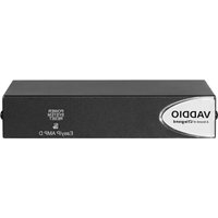
- AV Bridge 2x1
- Contents
- Overview
- About this Guide
- Features
- Unpacking the AV Bridge 2x1
- A Quick Look at the AV Bridge 2x1
- Front Panel
- Connector Panel
- Installation
- Note
- Don't Void Your Warranty!
- Caution
- Cabling Notes
- Pro Tip
- Basic Connections
- Basic Connections for Conferencing
- Using Dante Devices with AV Bridge 2x1
- RS-232 Serial Communication Settings and Port Pin-outs
- RS-232 connector pin-out:
- Powering Up
- Initial Device Set-Up and System Administration Tasks
- About the Web Interface
- Browser Support
- About the Vaddio Deployment Tool
- Initial Device Set-Up from the Web Interface
- Getting the Device's IP Address
- Initial Access to the Web Interface
- Warning: Potential Security Risk Ahead
- What can you do about it?
- Setting up the Web Interface
- Initial Device Set-Up Using the Vaddio Deployment Tool
- To complete the initial device set-up with the Vaddio Deployment Tool:
- Next Steps for New Deployments
- Setting Passwords and Access
- Configuring Other Security Settings
- For Non-DHCP Environments: Configuring the Device with a Static IP Address
- Changing the Device's Hostname
- Optional For DHCP Environments: Changing from a DHCP Address to a Static IP Address
- NETWORKING PAGE
- Adding Room Information
- ROOM LABELS PAGE
- Setting System Time and Time Zone
- Identifying Dante Devices
- To physically locate Dante devices:
- To rename a device in the Dante Controller application:
- Performance and Behavior Settings
- Configuring Audio Settings
- AUDIO PAGE (MULTIPLE TABS)
- Muting and Setting Volume
- Microphone Settings and Adjustments
- Enabling Phantom Power to Microphones
- Speaker Adjustments
- Synchronizing Audio with Video in the IP Stream
- AUDIO PAGE, STREAMING TAB
- Routing Audio
- AUDIO PAGE, MATRIX TAB
- Setting Gain Between Input and Output (Crosspoint Gain)
- Configuring Streaming Settings
- Supported Input Resolutions and Frame Rates
- Configuring USB Streaming
- Set IP Streaming Video Settings
- STREAMING PAGE
- To set up IP streaming in Custom quality mode:
- RTSP Streaming Settings
- To view the RTSP stream:
- RTMP Streaming Settings
- Notes
- To configure an RTMP streaming service:
- To select the enabled RTMP streaming service:
- Stopping the IP Stream
- Options:
- Advanced: Changing MTU
- Working with Video Inputs
- VIDEO INPUTS PAGE
- Configuring the Video Output
- Setting Video Transition Type and Speed
- Working with Graphics
- To upload a graphics file:
- To place the graphic on the canvas and work with it:
- To manage the graphics library:
- Setting up Macros and Triggers
- To edit an existing macro:
- To write and test a macro:
- Configuring Standby Behavior
- USER INTERFACE PAGE
- Locking the Front Panel
- Customizing Labels
- System Maintenance
- Exporting and Importing Configuration Data
- SYSTEM PAGE, FIRMWARE TAB
- To export a configuration:
- To import a configuration:
- Updating the Firmware
- Rebooting
- Contacting Vaddio Technical Support
- HELP PAGE
- Viewing Diagnostic Logs
- DIAGNOSTICS PAGE
- Operating the AV Bridge 2x1
- About Viewing Streams
- To view the IP stream:
- To view the USB stream:
- Muting and Video: Quick Steps You Can Take from Any Page
- Working with Cameras
- Working with Camera Presets
- HOME PAGE (USER OR GUEST ACCESS)
- Controlling Movement
- CAMERA PAGE (USER OR GUEST ACCESS)
- Working with Audio
- Working with Macros
- Going to Standby (Low Power) Mode
- ALL PAGES
- Serial Command API
- Usage notes:
- Typographical conventions:
- audio volume
- audio mute
- audio route
- audio crosspoint-gain
- streaming settings get
- streaming ip enable
- camera home
- camera pan
- camera tilt
- camera zoom
- camera preset
- camera ccu get
- camera ccu set
- camera ccu scene
- camera focus
- camera comm host
- camera standby
- video program pip
- video mute
- video type
- trigger
- network ping
- network settings get
- system standby
- system reboot
- system factory-reset
- version
- history
- help
- exit
- Troubleshooting and Care
- Video and Audio Issues
- Restoring Factory Defaults
- Restoring Factory Defaults from the Web Interface
- SYSTEM PAGE
- Restoring Factory Defaults from the Front Panel
- Operation, Storage, and Care
- Glossary
- AEC
- bandwidth
- DHCP
- DIY
- EasyMic
- echo cancellation
- far end
- felis catus
- full-duplex
- gateway
- HDMI
- HID audio controls
- HTTP
- HTTPS
- IP address
- IP address conflict
- LED
- MTU
- near end
- NTP
- PoE, PoE+, PoE++
- RCLB
- RTMP
- RTSP
- soft conferencing client
- SSL certificate
- standby mode
- streaming protocol
- subnet mask
- UAC drivers
- UCC, UC conferencing
- USB 2
- USB 3
- USB playback
- USB record
- UVC drivers
- UVC extensions
- Compliance and Conformity Statements
- FCC Part 15 Compliance
- ICES-003 Compliance
- Photo Credits
- Index
- A
- B
- C
- D
- E
- F
- G
- H
- |
- K
- L
- M
- N
- O
- P
- Q
- R
- S
- T
- U
- V
- W
- Z
- A brand of legrand®
Brand : Vaddio
Model : AV Bridge 2x1
Category : Commutateur audiovisuel