
MPC Live II - DJ Equipment AKAI - Free user manual and instructions
Find the device manual for free MPC Live II AKAI in PDF.


| Product Type | Standalone Music Production Center (MPC) |
| Model | MPC Live II |
| Display | 7-inch color touchscreen (1024x600) |
| Pads | 16 RGB velocity-sensitive pads (128 total with banks) |
| Q-Link Controls | 4 assignable Q-Link knobs |
| Storage | 16 GB internal (user available), SD card slot, USB drives |
| Audio I/O | 2 TRS inputs (Line/Phono switch), 2 TRS main outputs, 2 TRS headphone outputs |
| Audio Resolution | 24-bit / 96 kHz |
| MIDI I/O | 5-pin DIN In, Out, Thru; USB MIDI |
| Connectivity | Wi-Fi 802.11 b/g/n, Bluetooth 4.0, Ethernet 10/100 |
| USB Ports | 3 USB-A (host), 1 USB-B (device) |
| Power Supply | 12V DC, 3A (included adapter) or internal rechargeable battery |
| Battery Life | Up to 2 hours (built-in lithium-ion) |
| Dimensions (W x D x H) | 279.4 x 246.4 x 52.3 mm (11.00" x 9.70" x 2.06") |
| Weight | 1.32 kg (2.9 lbs) |
| Operating System | MPC 3 standalone (upgradable) |
| Main Functions | Sequencing, sampling, audio recording, drum programming, synthesizer plugins, song arrangement, effects processing, MIDI control |
| Care and Cleaning | Wipe with dry cloth; avoid liquids; remove protective film from touchscreen |
| Safety | Read included safety & warranty manual; turn off all devices before connecting |
| Spare Parts and Repairability | Contact Akai Professional support; internal storage upgrade not user-serviceable |
| General Information | Standalone operation; supports Ableton Live import (with Pro Pack); 128 tracks per project |
Frequently Asked Questions - MPC Live II AKAI
User questions about MPC Live II AKAI
0 question about this device. Answer the ones you know or ask your own.
Ask a new question about this device
Download the instructions for your DJ Equipment in PDF format for free! Find your manual MPC Live II - AKAI and take your electronic device back in hand. On this page are published all the documents necessary for the use of your device. MPC Live II by AKAI.
USER MANUAL MPC Live II AKAI
Recording Tracks with Main Mode 11
Main Mode Overview 11
Recording a Drum Sequence ....12
Creating and Recording a Keygroup Track ... 13
Adding and Recording with a Plugin Track .... 14
Working with Audio Tracks 15
Recording an External Instrument 15
Loading Sounds with the Browser ..... 16
Working with the Linear Arranger 17
Saving Your Work....19
Editing Note Events....20
Making Basic Sound Edits....22
Other Features Explained 24
Q-Links....24
Step Sequencer 25
Drum Loops & Chop Mode 26
Pad Muting & Track Muting 28
Sampling (Recording) 30
Sample Editing 32
Recording Automation with the XY Pad ..... 34
Creating a Song 35
Operation....37
General Features....37
Control Types 37
Knobs 37
Parameter Values 38
Drop-Down Menus / Lists.... 38
Selectors.... 39
Buttons 39
Checkboxes....39
Tabs....39
Sliders....40
Envelopes 40
Tracks 41
About Tracks.... 41
Audio Tracks 43
Drum Tracks 44
Keygroup Tracks 46
Plugin Tracks 48
MIDI Tracks....49
CV Tracks 51
Menu 52
Toolbar 53
Sync 53
Help....53
Undo History....53
Tuner 54
MIDI Monitor 54
Mode 54
System Resources.... 55
Project 56
Preferences....57
Info 57
Activations 57
Wi-Fi 58
Ethernet 58
Bluetooth 58
Audio Device....58
Audio/Export 59
MIDI / Sync 59
Hardware....60
Sequencer 61
Project Defaults.... 62
Project Load/Save 63
General 63
Splice 64
Save Window 65
Pull-Down Menu....67
Time Counter / Locate 69
Timing Correct (TC)....70
Metronome (Click/Metro) 72
Automation....73
Global 73
Tracks....73
16 Level 75
Pad Perform....76
Arpeggiator 79
Erase 82
Effects 83
Overview 83
Insert Effects 86
Pads and Keygroups....86
Tracks, Submixes, and Outputs 88
Send/Return Effects 90
Pads and Keygroups....92
Tracks and Submixes....94
Audio Mixdown 95
Keyboard Control 97
Touch Strip 99
Battery Usage 102
Modes 103
Main Mode 104
Overview 104
Toolbar 105
Shortcuts 105
Function Buttons....106
Sequence Section......107
Track Section....112
Drum Tracks....113
Keygroup Tracks....115
Plugin Tracks....116
MIDI Tracks 117
CV Tracks....118
Audio Tracks....119
Buses 120
Track Edit 121
Arrangement Section....124
Mixer Strips....128
Browser....131
Sample Assign....134
Channel Mixer 135
Volume....136
Pan & Volume 136
Sends 137
Effects....138
I/O 139
Pad Mixer 140
Volume....141
Pan & Volume 141
Sends 142
Effects....142
I/O 143
Sounds Mode 144
Favorites....145
Setlists....145
XYFX Mode 146
Arrange Mode 149
Recording Arrangements....151
Editing Arrangements....152
Arrangement Track Editor....159
Saving and Exporting the Arrangement .....160
Grid View 161
Audio Tracks....163
MIDI Tracks....166
Velocity/Automation Lane....172
Step Sequencer 173
Step Automation....177
List Edit Mode....178
Track Edit Mode 184
Drum Tracks 184
Global....186
Samples 188
Envelopes....196
Mods (Modulations)....199
Effects 200
LFO 203
Utilities 204
Mod Matrix 205
Keygroup Tracks....206
Global (Advanced and Legacy)....208
Samples (Advanced and Legacy) ......210
Filters (Advanced)....218
Envelopes (Advanced)....220
LFO (Advanced) 227
Utilities/Sensitivity (Advanced) 230
KG Stack (Advanced)....232
Mod Matrix (Advanced) 234
Randomize (Advanced) 235
Envelopes (Legacy) 236
LFO (Legacy) 239
Mods (Legacy) 240
Effects (Legacy)....241
Plugin Tracks 243
MIDI Tracks....244
CV Tracks 245
Anatomy of an Envelope....246
Track Mute Mode....247
Track Mute....249
Track Group....250
Pad Mute Mode 251
Pad Mute 253
Pad Group 254
Track View....255
Sample Edit Mode 258
Settings....260
Trim Mode 261
Assigning Samples....265
Processing Slices & Samples 266
Chop Mode....271
Converting or Assigning Slices 274
Processing Slices....277
Pad Mode....281
Assigning Samples....284
Processing Slices & Samples ....284
Sampler 285
Sample 288
Slice....290
Pad Tap....291
Pad Hold....292
Auto Sampler....293
Q-Link Edit....295
Learning Macro Assignments ......296
Editing Macro Assignments ....301
Q-Links 302
XY Pad 305
Crossfader 306
Next Sequence Mode 307
MIDI Learn 309
Live Control Mode 311
Setup 311
Control Bar....313
Matrix View 314
Mixer View....315
Device Control View 316
Q-Links 316
Song Mode 317
Key Ranges Mode 320
MIDI Control Mode 322
Pads 323
Buttons 324
Q-Link Knobs....325
XY Pad 326
Pad Color Mode 327
Looper....329
Hardware Features 333
MPC X / MPC X Special Edition 333
Top Panel 333
Navigation & Data Entry Controls......334
Pad & Q-Link Controls....334
Mode & View Controls....335
Transport & Recording Controls ....336
I/O & Level Controls 337
Front Panel....338
Rear Panel 339
MPC Live 340
Top Panel 340
Rear Panel 342
MPC Live II 343
Top Panel 343
Rear Panel....346
MPC One / MPC One+ ....347
Top Panel 347
Navigation & Data Entry Controls....347
Pad & Q-Link Controls....348
Mode & View Controls....348
Transport & Recording Controls ....349
Front Panel 350
Rear Panel....350
MPC Key 61 351
Top Panel 351
Rear Panel 355
MPC Key 37 357
Top Panel 357
Rear Panel....361
Appendix 362
Glossary 362
Effects & Parameters 366
Delay/Reverb....366
Dynamics 374
EQ/Filter 378
Harmonic....384
Modulation 393
Vocal 398
Plugins 400
Bassline....400
Electric 403
Hype....407
TubeSynth 412
DrumSynth 419
Mellotron 423
Solina 426
WayOutWare Odyssey 429
SATA Drive Installation 433
MIDI Machine Control (MMC) 434
Ableton Control Maps 435
MPC X / MPC X Special Edition 435
MPC Live 438
MPC Live II.... 440
Technical Specifications 442
MPC X / MPC X Special Edition 442
MPC Live 445
MPC Live II.... 447
MPC One / MPC One+ 449
MPC Key 61 451
MPC Key 37 454
Trademarks & Licenses 456
Addenda....457
MPC Pro Pack 457
MPC Clip Launching 457
Clip Matrix Mode....458
Navigate Mode....463
Clip Editor Mode 464
Main Mode - Arrangement & Clip Section .....466
Arrangement....466
Clips 467
Advanced CV Track Edit 472
Routing 472
Env 1-4....473
LFO 1-4....474
Stepper....475
Utilities 476
Matrix....476
Q-Link Edit – Envelope Follower / LFO ..... 477
Super Warp Algorithm 478
Pro Pack Plugins 479
AIR Visual EQ4....479
AIR Reverb Pro 480
AIR Utility 484
AIR Fabric Select....485
Import Ableton Live Projects 498
Introduction
Welcome to MPC 3, the latest advancement from Akai Professional for standalone MPC hardware.
This user guide explains how to create music using the MPC 3 operating system on first generation standalone MPC hardware, including: MPC X, MPC X Special Edition, MPC Live, MPC Live II, MPC One, MPC One+, MPC Key 61, and MPC Key 37.
Please note this manual does not cover the following:
- MPC Studio mk2 and MPC Touch, which are not supported on MPC 3.
- MPC Live III, which has a separate User Guide.
- Using MPC products with an LCD screen with the MPC software application.
- Using your MPC 3 supported hardware as a controller for the MPC Software.
For these products, or for information on MPC 2 operating systems, refer to the previous User Guides. To view these user guides, click the Help menu in the MPC software, select MPC Help, and select an option.
Support
For the latest information about this product (documentation, technical specifications, system requirements, compatibility information, etc.) and product registration, visit akaipro.com.
For additional product support, visit support.akaipro.com.
About This User Guide
This manual should help you get familiar with using your MPC X, MPC X Special Edition, MPC Live, MPC Live II, MPC One, MPC One+, MPC Key 61, or MPC Key 37 (from here on, "MPC hardware" unless otherwise noted) using the MPC 3 standalone operating system. For consistency, the terminology throughout is based on the MPC nomenclature. We also used specific formatting to indicate particular topics of significance:
Important/Note/Tip: Important or helpful information on a given topic.
Names of buttons, controls, parameters, settings, and other options are written in bold characters throughout the manual.
Examples: Press the Play button.
Turn Knob 4.
Tap the Mute icon.
The Velocity ranges from 0 to 127.
Set the Sample Play selector to One Shot.
Tap BPM, and then use the numeric keypad to enter a 120 as the tempo.
Some parts of this manual refer to other relevant chapters or sections, which are cited in bold, italic blue characters. Click the text to skip immediately to that section.
Examples: Read the Important Notes section before proceeding.
See Operation > General Features > Menu > Sync for more information.
To learn more about using send effects, see General Features > Effects > Send/Return Effects.
Important Notes
Read the included safety & warranty manual before using your MPC hardware.
Before getting started and connecting devices to your MPC hardware or turning the hardware on/off, make sure all devices are switched off.
MPC2 vs. MPC3
The transition from MPC2 to MPC3 introduces significant architectural changes, most notably the unification of tracks and programs into a single track container. This redesign aims to streamline and accelerate workflow, but also results in MPC2 projects not being loadable into MPC3 with identical behavior. Because of this, we strongly recommend saving a new copy of all MPC2 projects before importing to preserve editing capabilities.
Upon loading an MPC2 project, MPC3 will display a Project Import dialog. By default, the Import field is set to All Sequences. Using this method:
- MPC3 will attempt to import all sequences and tracks from the MPC2 project.
- If a single track was assigned to a single program in MPC2, MPC3 will create a corresponding track of the same type as the original program.
- If multiple tracks were assigned to the same program in MPC2, MPC3 will create one primary track of the same type as the program, and subsequent tracks will be converted to MIDI tracks with their Send To field pointing to the primary track.
Alternatively, you can set the Import field to Selected Sequences Import. Using this method:
- A list of sequences from the source MPC2 project will be displayed, and you can tick the sequences you wish to import into MPC3.
- The selected sequences will load into their original locations within the sequence list.
Updates in v3.6
MPC Pro Pack
MPC v3.6 provides support for the MPC Pro Pack. This is included automatically for all users of MPC Live III and can be purchased as an upgrade for users of other MPC standalone hardware that supports MPC3.
To purchase the MPC Pro Pack, visit thempcstore.com / akaipro.com. You can unlock the Pro Pack on up to three supported devices.
To unlock the Pro Pack, use the Activations tab of the Preferences.
The MPC Pro Pack includes:
- MPC Clip Launch: New Clip Matrix and Clip Edit modes.
• Advanced CV Track Edit.
• Advanced Q-Link Edit, including Envelope Follower and LFO.
• Super Warp algorithm - MPC3 Pro Pack Plugins: AIR Fabric Select, AIR Visual EQ4, AIR Reverb Pro, AIR Utility
- Import Ableton Live Projects
See Addenda > MPC Pro Pack to learn more about these features.
Project Time Signature Support
You can now change the time signature of your MPC project to suit your creative needs. Changing the project time signature updates all sequences to use the new setting. Sequences will retain their length in bars. If Clip workflow is enabled, clips will retain their length in pulses.
Project Time signatures can be changed in Main Mode. You can also set the default time signature in the Project Defaults section of the Preferences.
Track Edit Enhancements
MPC now includes an enhanced Track Edit mode for Drum Tracks, including:
- A powerful Drum Articulation Engine, allowing you access to typical drum articulations and rudiments like flams, paradiddles, and dynamic drum phrases which can be added to individual pads. You can also trigger and record different articulations using 16 Level, and Modifiers (editable in List Edit Mode) include an Articulation parameter.
- A 32-cell modulation matrix, for extensive routing options for complex modulation setups.
- New modulation sources, including an upgraded dual LFO, a Note Counter, dual Ramps, and Global and Per-Voice Drift LFOs.
- The Layer Play Offset parameter lets you shift a framed sample window—defined by Start, End, and Loop points—across the sample without altering their relative positions.
- The Global tab now includes a Pad Tuning parameter, altering the tuning of all layers on that pad.
Both Drums and Keygroups have the following additional enhancements:
- The Modulation Matrix now supports a hierarchical menu of sources and targets.
- Layer Play – Crossfade: This new setting allows you to crossfade between sample layers using modulation sources like Envelopes and LFOs in Drum and Keygroup tracks, enabling wave-sequencing or vector synthesis-like effects.
- Random Seeds: When Layer Play is set to Random, the Random Seed field displays a value between 1–999,999. This number can be copied and reused to reproduce the same random sequence across sessions or projects.
See Operation > Modes > Track Edit Mode > Drum Tracks or Keygroup Tracks to learn more.
MIDI Improvements
You can now configure individual pads within a Drum Track to send specific MIDI notes for triggering external gear, lighting, or video sources.
We've also expanded the MPC sequencer's MIDI capabilities with full per-event channel recording and routing. This update unlocks more flexible workflows for multi-timbral instruments and external MIDI gear.
Other Improvements
You can now input automation bounded by the length of a step in the Step Sequencer.
When using Pad Copy, pad colors are now copied.
In Main Mode, tapping and holding the Sequence field opens a new pop-up with the following settings:
Use the Name field to rename the Sequence.
Use the Auto-Select Track field to specify which track is selected when switching sequences. Select None to keep the current track selected when changing sequences, or select a specific track from your project.
Setup
Here is just an example of how to use MPC X in your setup. Items not listed under Introduction > Box Contents of your included Quickstart Guide are sold separately.
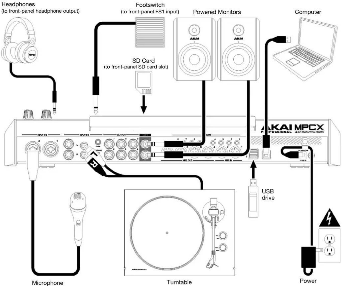
flowchart
graph TD
    A["Headphones (to front-panel headphone output)"] --> B["Footswitch (to front-panel FS1 input)"]
    B --> C["SD Card (to front-panel SD card slot)"]
    C --> D["Powered Monitors"]
    D --> E["Computer"]
    E --> F["Power"]
    F --> G["USB drive"]
    G --> H["Turntable"]
    H --> I["Microphone"]
    H --> J["Turntable"]
    J --> K["Microphone 1/2"]
    J --> L["Microphone 3/4"]
    J --> M["Microphone 5/7"]
    J --> N["Microphone 7/9"]
    J --> O["Microphone 9/11"]
    J --> P["Microphone 11/13"]
    J --> Q["Microphone 13/15"]
    J --> R["Microphone 15/17"]
    J --> S["Microphone 17/19"]
    J --> T["Microphone 19/21"]
Remember to remove the protective film from your MPC hardware touchscreen!
To use your MPC hardware in Standalone Mode, just connect it to a power outlet using the included power adapter, and power it on!
Note: We highly recommend checking akaipro.com for any available updates to the MPC software/firmware and/or drivers. You can also connect your device to Wi-Fi and check for updates in the Preferences menu.
Tutorial
For those new to MPC, this chapter should familiarize you with some of the basic features and modes. We'll create a short song to illustrate some of the most important features. To get the most out of this chapter, we recommend reproducing each of the described steps in order.
For in-depth information on the various features and modes in MPC3, proceed to the Operation chapter.
For a breakdown of all the controls on your MPC hardware, proceed to the Hardware Features chapter.
You can also access video tutorials from the Akai Professional YouTube page at youtube.com/AkaiProVideo.
Starting Up
When you first power on your MPC hardware, you will be presented with a welcome screen. Tap Next to continue.
Next, a help screen will appear with a QR code that links to this User Guide. Tap Got It to continue. You can also access this at any time from the Toolbar in the Menu.
You will then be prompted to connect your MPC hardware to the internet to check for the latest software update. We recommend always staying up-to-date with the latest software version. Tap Let's Go to dismiss this message. If you no longer want to see this message, tap the Don't show this again box before proceeding.
Your MPC will then display a list of demo projects to choose from. These projects cover a range of styles and are included to highlight the wide array of sounds available with MPC.
To begin this tutorial, we will instead start by selecting New Project at the bottom of the screen. In MPC 3, this will automatically load a small factory project by default. The configuration of this project varies depending on the type of MPC device in use.
For MPCs without a keyboard (MPC X/X SE, Live/Live II, One/One+):
- Drum Track Preset: A single drum track with samples loaded on Pad Bank A.
• Q-Link Screen Layout: Configured to control settings and features in Main Mode.
• Effects: AIR Reverb and AIR Delay are preloaded on Returns 1 and 2.
MPC Key 61:
- Drum Track Preset: Same as MPCs without a keyboard.
- Plugin Instrument Tracks: Four plugin instrument tracks are added before the drum track.
• Effects: AIR Reverb and AIR Delay are preloaded on Returns 1 and 2.
MPC Key 37:
- Drum Track Preset: Same as MPCs without a keyboard.
- Plugin Instrument Tracks: A single plugin instrument track is added before the drum track.
• Effects: AIR Reverb and AIR Delay are preloaded on Returns 1 and 2.
Recording Tracks with Main Mode
Main Mode Overview
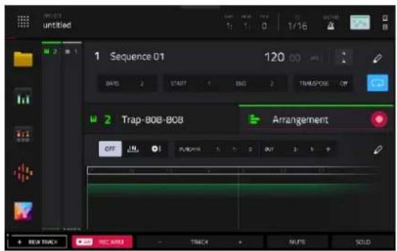
Your project will begin in Main Mode, which provides visual feedback and fast access to many of MPC's key features.
The image below shows an overview of Main Mode. You can view more information about all the features mentioned below in the Main Mode chapter later in this User Guide. For now, this will help familiarize you with the different parts of this page as you progress through the tutorial.
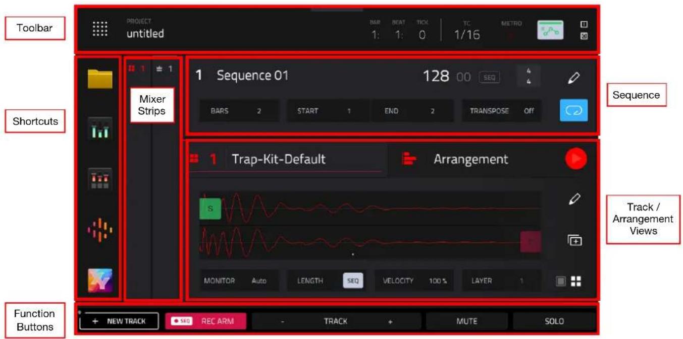
Begin with the Track / Arrangement View. When the new project is loaded, the Track view will be selected. This allows you to navigate between your project's available tracks.
Tap the track header and make sure the drum track is selected (MPC Key 61 users will want to scroll to Track 5, and MPC Key 37 users will want to scroll to Track 2). Once selected, you can hit each pad to hear the assigned sample and view a simple waveform editor, where you can adjust sample start and end points. Double-tapping this area will take you directly to Track Edit Mode, where you can apply more advanced editing techniques.
Next, tap the Arrangement header to show the Arrangement view. Here, you can see all the MIDI or audio events recorded on the selected track. Double-tapping this area will open the full Grid View, where you can edit your MIDI notes or audio events for the selected track.
Recording a Drum Sequence
Using these areas, and the pre-loaded drum kit track, let's start by recording a basic drum sequence:
- Make sure the ● SEQ REC ARM button at the bottom of the screen is enabled, and then press the REC button on your MPC hardware to arm the arrangement for recording.
- Select the Arrangement view by tapping the header.
- Press the Play button to start the actual recording. You will hear the metronome count-in for one measure before the recording starts. We recommend recording only one sound (pad) at a time, especially if you're not familiar with playing drums on the pads.
- Play a simple hi-hat pattern. The note events you just recorded will automatically be placed in the arrangement. The initial measure length is two bars. After the two bars, the recording will automatically activate Overdub; the sequence will play again from the beginning and keeps looping, allowing you to record further notes. Don't stop the recording!
Tip: Try spicing up your recorded pattern by enabling Note Repeat on your MPC hardware. Press and hold this button, and then tap to select 1/16 and T at the bottom of the screen. Now try adding some triplet hi-hat notes to your current sequence as you record.
- Next, play a kick drum part, and then a snare drum part.
- When you're done recording, press the Stop button.

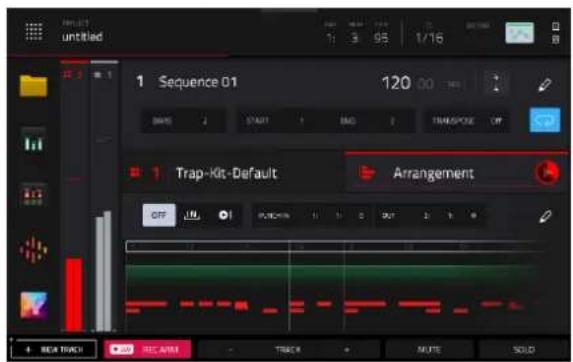
If you start recording again on this sequence, keep in mind that the pads you play in your new recording will replace existing notes played with the same pads. To prevent this, press the OVERDUB button before recording instead of the REC button. Overdub lets you record additional note events over the existing sequence.
If you made a mistake while recording, you can simply press UNDO on your hardware to undo the last event (or events) recorded if playback is stopped. If you are currently recording, the UNDO button will flash, and pressing it will erase all events from that recording (i.e., since PLAY or PLAY START was pressed).
Creating and Recording a Keygroup Track
With a basic drum part down, you can now start adding to your sequence. Pad 5 in the default drum kit features an 808 sound. We can use this sound to create a pitched bass sound by turning it into a Keygroup track. Keygroup tracks take a sample and allow you to play it chromatically with your MPC pads (or a MIDI keyboard).
- With the default drum track still selected, press Pad 5 on your MPC hardware to select it. Then, double-tap the sample area in the Track View of Main Mode. This will take you directly to Track Edit mode.
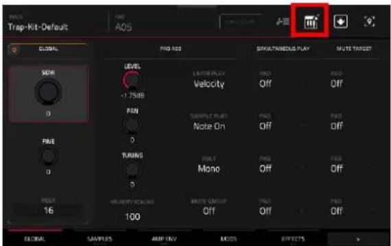
- Tap the keyboard+ icon at the top of the screen to instantly turn this 808 sample into a Keygroup Track.
- Press Main on your MPC hardware to return to Main Mode, and then select your new keygroup track. It will be added at the end of your current tracks.
- Your MPC hardware's pads will now be in Pad Perform mode as well. This will allow you to play the sample melodically.
- Make sure the ● SEQ REC ARM button at the bottom of the screen is enabled, and then press the REC button on your MPC hardware to arm the arrangement for recording.
- Press Play to begin playback and record a bass part using your MPC pads and the 808 sound.

Adding and Recording with a Plugin Track
Let's try adding another new track to the sequence. This time, we'll use one of MPC's built-in plugin instruments to add a melodic line.
- In Main Mode, tap + New Track at the bottom-left corner of the screen.
- A window will appear where you can select what type of track you want to add. Select Plugin to add a new plugin instrument track at the end of your current tracks.
- Use the Plugin field to select the desired plugin, and then use the Preset field to select a preset.
- Once you are ready, make sure the ● SEQ REC ARM button is enabled, and then press the REC button to arm the arrangement for recording.
- Press Play to begin playback and record a new melodic part on your MPC pads.


Working with Audio Tracks
So far, the tracks we have used and added have all been MIDI-based tracks. You can also use Audio tracks in your project to add recorded sounds in different ways. In the following sections, we will introduce recording an audio sample from an external instrument and adding samples using the Browser.
To begin, press Main to go back to Main Mode. Tap + New Track at the bottom-left corner of the screen, and then select Audio. A new audio track will be added to the project.
Recording an External Instrument
To record audio from an external instrument or microphone:
- Select the audio track in the Track View area, and then tap the icons at the top of the Channel Strips to expand them.
- Tap to select the I/O tab of the track channel strip.
- Tap the Monitor field to select it, and then turn the data dial on your MPC hardware until Auto is selected. With the track armed for recording, If you start playing your instrument, you should now hear it and see the signal coming into the track. This will allow you to hear your input when the track is armed for recording.
- Connect a line-level audio source to the 1/4" (6.35 mm) input/inputs on your MPC hardware's rear panel, and set the Line/Phono selector to Line (MPC X, MPC Live, MPC Live II), or set the Inst/Line selector to Line (MPC Key 61). Then, make sure the Audio In field is set to the input or inputs where you've connected your instrument.
- Press Rec to arm the arrangement for recording.
- If you start playing your instrument, you should now hear it and see the signal coming into the track. As needed, turn the 3/4 Rec Gain (MPC X), Rec Vol (MPC Live, MPC Live II, MPC One, MPC Key 37), or Gain (MPC Key 61) knob to set the input level while playing your audio source. Make sure it does not exceed the maximum level (the meter should not be “peaking” constantly).
- Press Play or Play Start to start recording. Now play your audio source! You should hear your existing sequence playing in the background.
To stop recording, press Stop.


Later in this manual, you can also learn about recording using the Sampler or Looper. You can also apply these same principles to recording audio directly into Drum Tracks.
Loading Sounds with the Browser
You can also browse and add previously recorded samples, either those included with MPC or your own, to an audio track.
To add a recorded audio sample to an audio track:
- From Main Mode, tap the file folder icon in the Shortcuts panel on the left side of the screen to open the Browser. You can also do this by pressing the Menu button and then tapping Browser.
- On the left side of the Browser screen, tap the Content header. This will allow you to browse files by content. Tap Samples to show the list of included audio samples with your MPC.
- Let's search for a vocal sample to add to our loop. Tap the Search bar and use the keyboard that appears on screen to search for the key word "Vocal." This will display included samples that are marked as vocal samples.
- As you scroll through the list, either by swiping up or down or using the encoder on your MPC hardware, you can preview a sample by tapping and holding the Play icon (▶). You can also adjust preview setting by tapping Audition at the bottom of the screen, and then using the window that appears to adjust the preview volume, enable auto-audition, and more.
- Once you have found a sample or samples you like, tap the Load to Pool button to add it to the project sample pool.
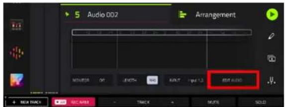
- Press Main to return to Main Mode. In the Track section of your audio track, tap the Edit Audio button. This will open Grid View, where you can add and edit samples in your audio track.
- Tap the Browse Samples button to open the Add Sample window, and then use the Sample field to select a sample you loaded. When the Place at start option is checked, this sample will be added at the start of your sequence. You can uncheck this to specify a different location, but you can also freely move and edit the sample after adding it.
- Once your sample has been added, see how it sounds as part of your sequence. You can use the Grid View editing tools to edit the start and end points of the sample, trim it, move it, apply fades, and even reverse it with the touch of a button. Try experimenting with some simple edits to your sample!

![[Internal] The Vault 2 Place Demand Options Vocal Sample Chill Trap-Vocal-CT1 Voc1.WAV Chill Trap-Vocal-CT1 Voc2.WAV Chill Trap-Vocal-CT1 Voc3.WAV Chill Trap-Vocal-CT1 Voc4.WAV Chill Trap-Vocal-CT2 Voc1.WAV Chill Trap-Vocal-CT2 Voc2.WAV Chill Trap-Vocal-CT3 Voc1.WAV SAMPLE ASSIGN LOAD TO POOL LOAD](/content/2026/05/883354/images/2dc05abb77779ce5fbef30856bd12a9a112d9f25592fc43f2c3500ebff48f529.jpg)


Working with the Linear Arranger
To take your track further, you can use Arrange Mode to record, edit, and arrange your sequences on a DAW-style linear timeline. Now that you've recorded a few tracks, open Arrange Mode by pressing Menu and then tapping Arrange.
Let's start by using the Arrange sequence editing tools to expand the length of our sequence.
- Tap the pencil Edit button at the top of the Arrange screen to open the Sequence Edit window.
- Tap the Double length button to instantly double the length of your sequence, including all recorded events. In this example, the sequence has been doubled from 2 bars to 4 bars. We will repeat this process again to double the sequence from 4 bars to 8 bars.
- Next, let's try adding a new section in between these bars. Tap the pencil Edit button again, and this time select Insert Bars. Set the # of Bars field to 2, set the Before Bar field to 5, and then tap Do It. This will add two blank bars between the two four-bar phrases.

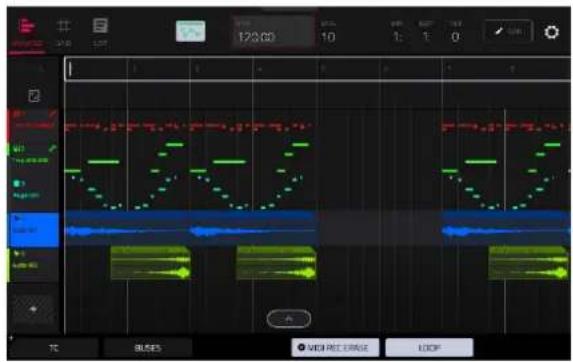
Next, let's fill in these empty bars in two ways. Perhaps you want to continue the same drum beat over these two bars, but change the melody. We can start by copying over notes from our drum track into this section. You can do this using the Copy Events function in the Sequence Edit window, but it is also easily accomplished using the Arrangement Track Editor.
- Tap your drum track to select it.
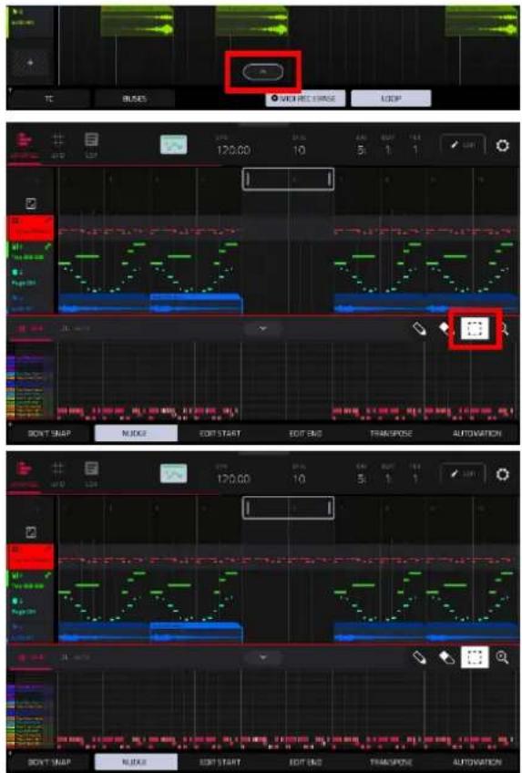
- At the bottom of the Arrange window, tap the up arrow ( ) to expand the Arrangement Track Editor. This is a fully featured grid editor (the same as Grid View mode) where you can add, remove, and edit note events.
- Tap the box icon to use selection mode.
- Tap and drag your finger over the recorded drum notes in the two bars before your empty bars.
- Once selected, press and hold Shift on your MPC hardware, and then tap Duplicate. This will instantly duplicate the selected events on the next available beat marker. As needed, tap Nudge at the bottom of the screen to enable note nudging, and then turn the data dial on your MPC hardware to adjust the position of the duplicated notes so they start on the downbeat of the bar.
You can also record into a section of the arrangement with a new performance.
- Tap the Loop button at the bottom of the screen to activate loop.
- Set the Loop Start and Loop End points by tapping and dragging the beginning and end of the loop region in the timeline. Tapping and dragging in the middle of the loop region moves both the Loop Start and Loop End points at the same time. Move the loop so it covers the two new bars we created.
- Select the track where you want to record by tapping the track header on the left side of the screen. If the ● SEQ REC ARM button was already enabled in Main Mode, this will automatically enable this track for recording. You can also double-tap the track header to bring up the Track Settings window, and then set the Rec Arm field to On.
- Press REC to arm recording and then Play to begin recording. The recording will begin at the Loop Start point, and once it reaches the Loop End Point, will switch to Overdubbing mode.
- Record a new melody using the MPC pads.


Saving Your Work
Now would be a good time to save your project. Press Menu to show the Menu, and tap the Save at the bottom of the screen to open the Save window.

The options displayed in this window may differ based on the type of track you have selected. For now, simply tap the Project As button to save your project as a new file. A new save window will appear where you can choose your save location and name your file.
To select the storage device you want to view, tap it in the Storage column on the left.
Internal is the internal drive of your MPC hardware.
MPC Documents is a shortcut to the MPC Documents folder on the internal drive of your MPC hardware.
If you have storage devices connected to USB ports or SD card slot of your MPC hardware, they will appear in this column, as well.
Double-tap a folder to enter it.
Tap New Folder to create a new folder. Use the virtual keyboard that appears to enter a name, and then tap Do It. You will immediately enter the new folder.

Tap the folder/ icon in the upper-left corner to move up one folder level.
Tap the File Name field at the bottom of the screen to name the file using the virtual keyboard that appears.
Tap Save to save the file.
Tap Cancel to cancel and return to the Menu. Alternatively, tap the ← icon in the upper-left corner.
Editing Note Events
As you record, you may want to make more in-depth edits to your note events or recorded audio. In the grid, you can see your recorded notes (or note events) as a sequence.
To enter the Grid View, press Menu, and then tap Grid View.
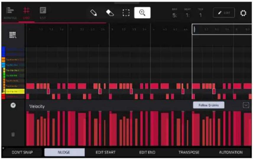
In the Grid View, you can do any of the following:
Tap the magnifying-glass icon in the upper-right corner to enable zoom control. Then, in the grid, spread two fingers apart or pinch two fingers together. You can do this for each axis, horizontal or vertical.
Tap the grid-and-magnifying-glass icon in the lower-left corner to automatically set the grid to view the active area, up to three pad banks and 32 bars.
Press Undo to undo your last action. Press Shift and Undo/Redo to redo the last action you undid.
To enter a note, tap the pencil icon at the top of the screen. Then, in the grid, tap a square.
To delete a note, tap the eraser icon at the top of the screen. Then, in the grid, tap a note.
To select a single note, tap the select box at the top of the screen. Then, in the grid, tap the note.
To select all notes for a pad, press the desired pad. (This can be enabled or disabled using the Hitting Pad Selects All Events option in the Grid Settings, accessed by tapping the gear icon in the upper-right corner of the screen.)
To move the selected notes, tap Nudge at the bottom of the screen, and then use the data dial or - / + buttons to shift the notes left or right. By default, you can position notes only by quantization values defined by the Time Correct value (learn about this feature in Operation > General Features > Timing Correct (TC)).
To move the selected notes without restricting ("snapping") them to the quantization grid, tap Don't Snap in the lower-left corner of the screen, and then use the data dial or - / + buttons to shift the notes. By default, each nudge is equivalent to one tick.
To adjust the start point or end point of the selected notes (without changing their position), tap Edit Start or Edit End at the bottom of the screen, and then use the data dial or - / + buttons.
To transpose the selected notes up or down, tap Transpose at the bottom of the screen, and then use the data dial or - / + buttons.
To open the Timing Correct window, tap the clock icon next to the automation parameter.

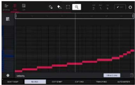
To show or hide the automation lane, tap the up arrow (∧) button in the lower-right corner of the screen to show the velocity lane below the grid. By default, note Velocity is selected, and each note's velocity is represented by a vertical bar. The higher and redder the bar is, the higher the velocity is.
To adjust the velocity of selected notes, tap Automation at the bottom of the screen, and make sure Velocity is selected as the automation lane parameter. Then, use the data dial or - / + buttons, or tap and drag up or down on a selected note. The numeric value will appear on the screen.
Making Basic Sound Edits
In addition to editing note events themselves, you may want to edit the sound of your samples, such as by changing the sample level and pitch, adjusting envelopes, or adding modulation and effects. These operations can be done using Track Edit Mode.
To enter Track Edit mode, press Menu, and then tap Track Edit to enter Track Edit Mode. Alternatively, press Prog Edit (MPC X, MPC One), or Edit (MPC Key 61, MPC Key 37).
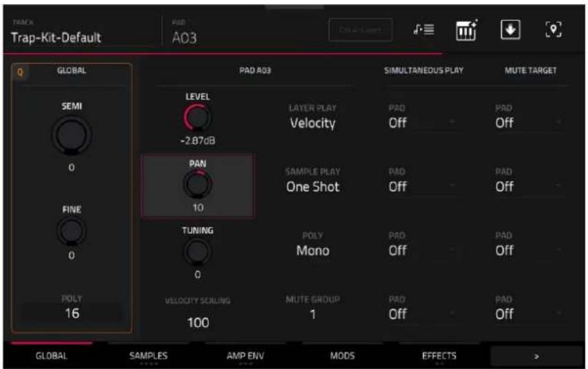
Let's make sure the samples are properly tuned and have good levels.
Press a pad to show its parameters on the screen.
To adjust its volume, tap and drag the Level knob up or down. Alternatively, use the data dial or - / + buttons. To make finer adjustments, double-tap the knob and adjust the larger version that appears. Tap anywhere else to return to the previous screen.
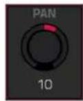
To adjust its stereo panning, tap and drag the Pan knob up or down. Alternatively, use the data dial or -/+ buttons. To make finer adjustments, double-tap the knob and adjust the larger version that appears. Tap anywhere else to return to the previous screen.
Adjust the level of each pad to suit your taste. We recommend spreading the panning of the bright sounds (e.g., cymbals, snare drum) a little. Additionally, you can tune the kick drum sound—tap the Samples tab so the second square under it is lit, and then adjust the Semi and Fine knobs next to the sample name.
The snare drum may need some reverb to give it a more spatial sound.
Tap Effects at bottom of the screen so the first square under it is lit to view the Insert Effects tab. Press the pad with your snare drum sound to select it.
![TRACK Trap-Kit-Default PAD A02 INSERTS 1 Reverb Medium [2 in 2 out] 2 NO EFFECT 3 NO EFFECT 4 NO EFFECT GLOBAL SAMPLES AMP ENV MODS EFFECTS ALL ON SEND 1 0 SEND 2 0 SEND 3 0 SEND 4 0 SEND 5](/content/2026/05/883354/images/b5ec77e6f35371879793908df37580630d9564768f52e1c5edf2847ba84f3765.jpg)
To add an effect:
- Double-tap the desired slot. A list of effects will appear.
- Swipe up or down to move through the list.
- To load an effect, double-tap it. Alternatively, tap it once and then tap Select or push the data dial. Let's try Reverb Medium.
- To close the list, tap Close.
To adjust the effect's parameters, tap the pencil icon.
To empty the effect slot, tap the trash can icon. Switch the effect on or off by tapping the On/Off button for the slot.
Other Features Explained
Now that you've learned some basic concepts, this chapter describes various advanced features. For a fuller explanation of these features, please refer to their corresponding sections in the Operation chapter.
Q-Links
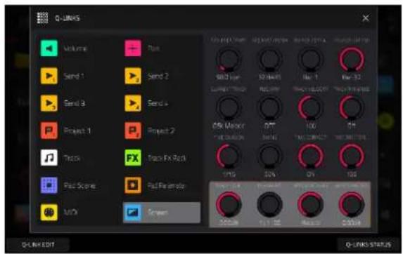
Your MPC hardware features Q-Link knob controls, which allow you to quickly manipulate various parameters on screen or in your project.
For MPC X/X SE users, the current Q-Link control parameters are shown on the display strips above each knob, and you can use the Q-Link buttons to switch between the different Q-Link modes.
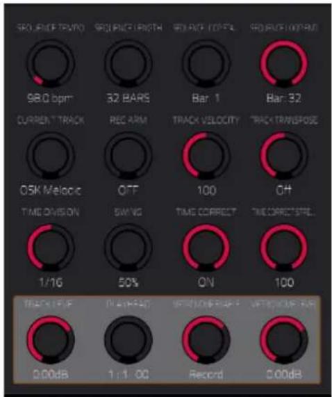
For all other MPC hardware, Q-Link controls are divided into four banks, which can be cycled through using the Q-Link button. In some modes, the current control or controls that are within Q-Link Screen mode control are outlined by a yellow box marked with a Q.
You can also press and hold the Q-Link button to open the Q-Link window, where you can switch between Q-Link modes and view the current Q-Link controls. If you are new to MPC, you may wish to enable the Q-Link Status feature, which will temporarily open a pop-up on the right side of the screen whenever a Q-Link is touched, displaying the current controls and values.
See the Q-Link Edit section to learn more about how to use Q-Links.

Step Sequencer
You've already learned how to record note events on a track, but you can also quickly enter note events in the Step Sequencer by using the pads as "step buttons," simulating the experience of a traditional step-sequencer-style drum machine.
To enter the Step Sequencer, press Menu, and then tap Step Sequencer. You can also press Step Seq (MPC X, MPC Live II, MPC One), or Shift and Grid/Step Seq (MPC Key 61, MPC Key 37).

bar
| Category | Value | |---|---| | Track Length | 32 | | Bar | 98.00 | | Speed | 6:3:24 | | Breakpoint | 1-16 | | Output | 16 | | Output Speed | 16 | | Output Step | 16 | | Output Time | 16 | | Output Duration | 16 | | Output Label | TC | | Output Label | - | | Output Label | BAR | | Output Label | + | | Output Label | PAD SEL | | Output Label | - | | Output Label | PAD | | Output Label | + |- Trying creating a new sequence. In Main Mode, tap Sequence 1 to select it, and then use the data dial or the + button to switch to Sequence 2. This will be shown as “(unused)” until it is edited.
- Select the original drum track from your first sequence, then enter Step Sequencer mode using the directions above.
- Tap the Bars field at the top of the screen, and then use the data dial or the - / + buttons to select a length.
Tip: The Track Length selector allows you to maintain tracks of different lengths by selecting Track instead of Sequence. For instance, you could play a 1-bar drum sequence repeatedly under a 4-bar bass line.
-
Tap the Bar -/+ buttons at the bottom of the screen to select the bar whose steps you want to create or edit. The bar number will appear in the Bar field in the upper-left corner.
-
Tap the Pad -/+ buttons at the bottom of the screen to select the pad whose steps want to create or edit. The pad number will appear in the Pad field in the upper-left corner.
-
Press Play to start your sequence. The current step is marked in green.
-
Each pad represents a step in the bar. If the pad already has note events on the selected track, the corresponding pads (steps) will be lit with colors corresponding to their velocities.
To enter a note at a step, press an unlit pad or tap an unlit step marker. The pad will light up with a color corresponding to its velocity. On the screen, the step marker will light up blue and a bar will appear showing the corresponding velocity.
To delete the note from a step, press a lit pad. The pad will become unlit.
To delete all notes from the current page view, press and hold Shift, and then tap Clear Page in the lower-right corner.
See Operation > Modes > Step Sequencer to learn more about this feature.
Drum Loops & Chop Mode
Modern music producers often use drum loops to add grit and nuance to programmed beats. This section explains how to use Sample Edit Mode to work with drum loops.
Use the Browser to locate a drum loop. If you have a pad selected in a Drum Track, you can tap Load to instantly add it to the kit. You can also tap Load to Pool to load it to the general sample pool of your project. The loop does not have to match the tempo of anything in the project.
To enter Sample Edit Mode, press Menu, and then tap Sample Edit. Alternatively, press Sample Edit (MPC X, MPC One, MPC Key 61, MPC Key 37), or Shift and Mute/Sample Edit (MPC Live II).

- Tap the Sample field at the top of the screen, and then use the data dial or - / + buttons to select a loaded drum loop. You can scroll through all loaded samples in the project. Alternatively, double-tap the Sample field, and then tap a sample to select it.
- Tap the Trim/Chop tab in the lower-left corner to switch between Trim Mode and Chop Mode. Select Chop Mode, which will let us cut the drum loop into slices.
- Tap Threshold, and then tap the Threshold field to the right of it. Use the data dial, - / + buttons, or numeric keypad (MPC X) to select a value. Alternatively, double-tap the Threshold field and use the numeric keypad on the screen. The lower the threshold, the more slices will be created. Be sure to select a value so that every transient peak of the drum loop has a corresponding a slice marker.
Tip: Each slice will be automatically assigned to a pad: Pad A01 plays Slice 1, Pad A02 plays Slice 2, etc. Press each pad to play the slice with the same number.
Let's use this chopped sample to create a new track in which each of these slices is an individual sample. We can also automatically create corresponding note events to play back these slices sequentially.
- Press and hold Shift and then tap Convert at the bottom of the screen to enter the Convert or Assign Slices window.
- Tap the Convert To field, and then use the data dial or -/+ buttons to select New Drum Track Using Slices.
- Make sure Create Events is checked. If it is not, tap it.
- Tap the Bars field, and then use the data dial or -/+ buttons to select how many bars the entire sample should use in your track.
- Tap Do It to proceed. Each slice will be assigned to a pad, and each pad will have a recorded note event in the track. When you play that track, it will play each pad (each slice) in the original order. Press Menu and then tap Grid View to see how the sample appears in your sequence.
- Press Play and listen to how the drum loop matches your song tempo now.
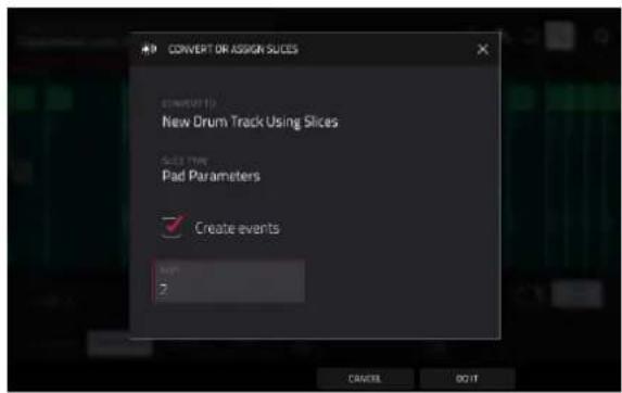
You can also edit the note events of the drum loop slices—enter Main Mode to do this. A new track with the note events playing their corresponding slices has been automatically created. Tap the TC/clock icon at the top of the screen to use the Timing Correct window to quantize the note events so they fall on exact, even time intervals.
You can also rearrange the note events, thus creating a new playback order for the slices. You can also edit each slice or sample in Track Edit Mode. You can add effects for slices or use the filter function to change the frequency range of a selected slice. You can even convert your chopped sample to an audio track instead, using the Audio Track from Samples option in the Convert menu. There are almost no limits to what you can do.
See Operation > Modes > Sample Edit Mode > Chop Mode to learn more about these features.
Pad Muting & Track Muting
Pad Mute Mode and Track Mute Mode let you silence different pads and tracks to see what the sequence sounds like without those samples or parts.
To enter Pad Mute Mode, press Menu, and then tap Pad Mute. Alternatively, press Shift and Track Mute/Pad Mute (MPC X, MPC One, MPC Key 37), or Shift and Mute/Pad (MPC Key 61).

- Press Play to play the sequence.
- Tap the Track field at the top of the screen, and then use the data dial or -/+ buttons to select your drum track. Alternatively, double-tap the Track field, and then tap a track to select it.
- Mute a pad by pressing it once or tapping it on the screen. The muted pad will be lit orange. You can mute multiple pads at the same time.
See Operation > Modes > Pad Mute Mode to learn more about pad mutes.
You can also mute entire tracks by using the similar Track Mute function.
To enter Track Mute Mode, press Menu, and then tap Track Mute to enter Track Mute Mode. Alternatively, press Track Mute (MPC X, MPC One, MPC Key 37), or Mute (MPC Key 61).
- Press Play to play the sequence.
- Tap the Sequence field at the top of the screen, and then use the data dial or - / + buttons to select the desired sequence. Alternatively, double-tap the Sequence field, and then tap a sequence to select it.
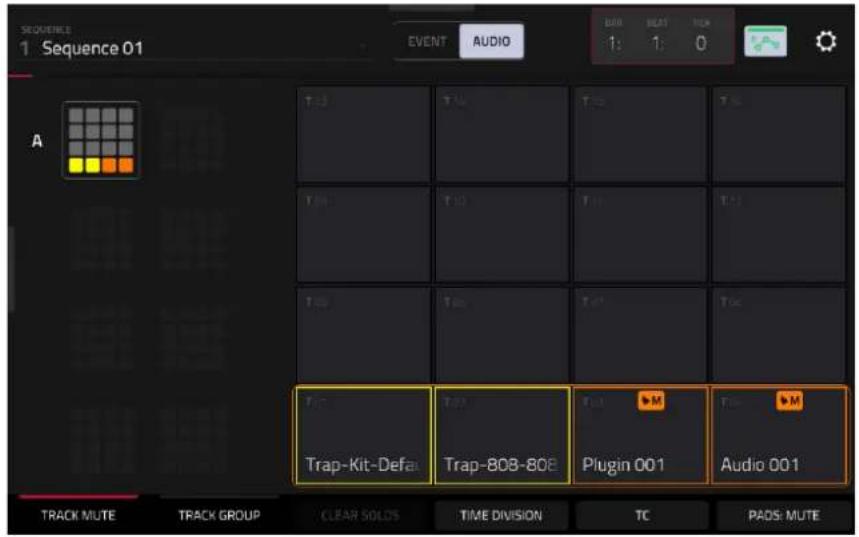
- Each pad is assigned to a track. Mute a track by pressing the corresponding pad or tapping it on the screen. The pad will be lit orange. You can mute multiple tracks at the same time.
Tip: To mute a track only at precise note intervals (“quantizing” your mutes, essentially), tap Time Division to set a musical timing value. Tap the desired musical value (e.g., 1 Bar). Tap Close to close the page. Now, when you press a pad in Track Mute Mode, the mute will occur precisely at the beginning of the following time division (in this example, one bar). This lets you test musical combinations of patterns—the preliminary stage to building a song structure.
See Operation > Modes > Track Mute Mode to learn more about track mutes.
Sampling (Recording)
Earlier in this tutorial, we described recording audio from an external instrument directly into your arrangement. You can also record from an external instrument to create samples that can be used in other ways in your project. This can be done using the Sampler function.
To open the Sampler, press Menu, and then tap Sampler. Alternatively, press Sampler (MPC X, MPC One), press Shift and Mix/Sampler (MPC Live II), or press Shift and Sample Edit/Sampler (MPC Key 61, MPC Key 37).
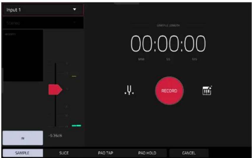
- Connect an audio source to the input/inputs of your MPC hardware.
- The Input __ menu in the upper-left corner should be set to Input 1,2 (the inputs of your MPC hardware). If it is not, then select Input 1,2.
- Turn the 3/4 Rec Gain (MPC X), Rec Vol (MPC Live, MPC Live II, MPC One, MPC Key 37), or Gain (MPC Key 61) knob to set the input level while playing your audio source. You should now see the level in the meter. Make sure it does not exceed the maximum level (the meter should not be “peaking” constantly).
- Tap and drag threshold slider to set the threshold. Alternatively, use the data dial or - / + buttons. Set it to a fairly low level (e.g., -50 dB).
- Tap Arm to record-arm the Sampler.
- Play your audio source. The Sampler will start recording immediately when the input level reaches the threshold value. Alternatively, tap the round Record button to manually start recording.
- To stop recording, tap the round Stop button. The Keep or Discard Sample window will appear.

In the Keep or Discard Sample window:
Tap the Name field to name the new sample using the virtual keyboard.
Use the Track field to select the desired track. Tap to select it, and then use the data dial or - / + buttons to select the track. You can also double-tap this field to open the list of tracks, and then tap to select your track.
Use the Assign To Pad field to assign the sample to a pad in your track. You can tap this field and then press the desired pad, use the data dial or - / + buttons to select the desired pad number, or double-tap the Pad field, and then tap a pad number.
Use the Root Note field to set the root note for the sample. Tap the field and then then use the data dial or - / + buttons to select the desired note.
Tap the Save button at the bottom of the screen to save the sample.
Tap the Play button at the bottom of the screen to play the recording.
Tap the Discard button at the bottom of the screen to discard the recording and return to the previous screen.
Tap Keep at the bottom of the screen to confirm your selections.
Tap the Edit button at the bottom of the screen to edit the sample in Sample Edit Mode.
See Operation > Modes > Sampler to learn more about this feature.
Sample Editing
You may need to edit your newly recorded samples using Sample Edit Mode.
To enter Sample Edit Mode, press Menu, and then tap Sample Edit. Alternatively, press Sample Edit (MPC X, MPC One, MPC Key 61, MPC Key 37), or press Shift and Mute/Sample Edit (MPC Live II).

In Sample Edit Mode:
Tap the Trim/Chop tab at the bottom of the screen to switch between Trim Mode and Chop Mode. In this example, use Trim Mode.
To set the sample's start point, use the first column of Q-Link knobs (when in the Screen Q-Link Edit Mode) to adjust the start point with varying degrees of resolution. Alternatively, tap and drag the S marker in the waveform. You can also double-tap the Start field and use the numeric keypad on the screen to enter a value (or tap the Start field and use the numeric keypad [MPC X only]).
To set the sample's end point, use the second column of Q-Link knobs (when in the Screen Q-Link Edit Mode) to adjust the end point with varying degrees of resolution. Alternatively, tap and drag the E marker in the waveform. You can also double-tap the End field and use the numeric keypad on the screen to enter a value (or tap the Start field and use the numeric keypad [MPC X only]).
To hear your edits, press Pad 10 to play the sample from the start point to the end point.
Let's apply some processing to the sample.
To open the Process Sample window, tap Process at the bottom of the screen.
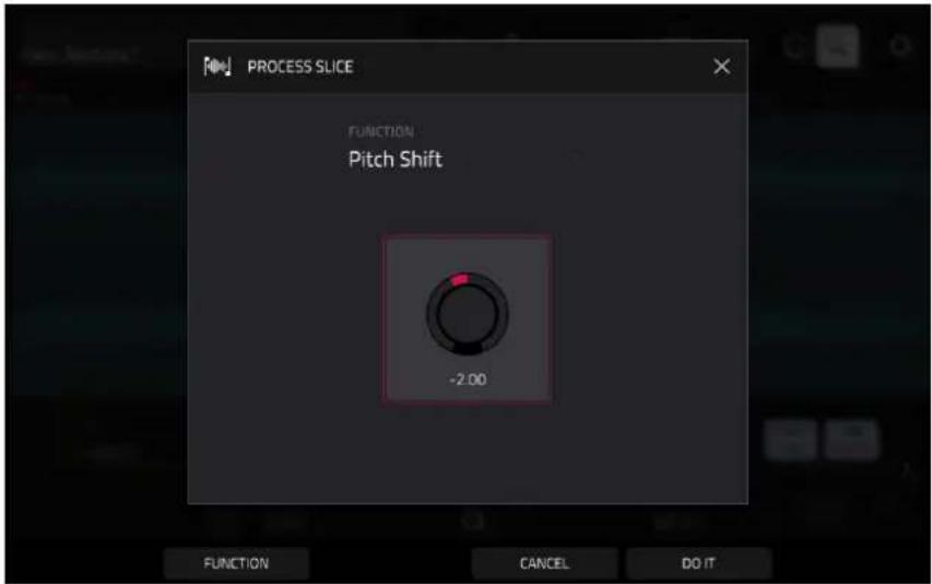
- Use the data dial or - / + buttons to select the desired process in the Function field. Alternatively, tap Function or double-tap the Function field, and then tap the desired process. Let's select Pitch Shift to change the overall pitch of your sample. This will transpose the sample without affecting its length.
- To set the pitch shift amount, tap and drag the knob in the center of the window up or down. Alternatively, use the data dial or -/+ buttons.
To make finer adjustments, double-tap the knob and adjust the larger version that appears. Tap anywhere else to return to the previous screen.
- Tap Do It to confirm your selections, or tap Cancel to cancel the process.
See Operation > Modes > Sample Edit Mode to learn more.
Recording Automation with the XY Pad
Automating various parameters is a good way to add some motion and dynamism to your sequences.
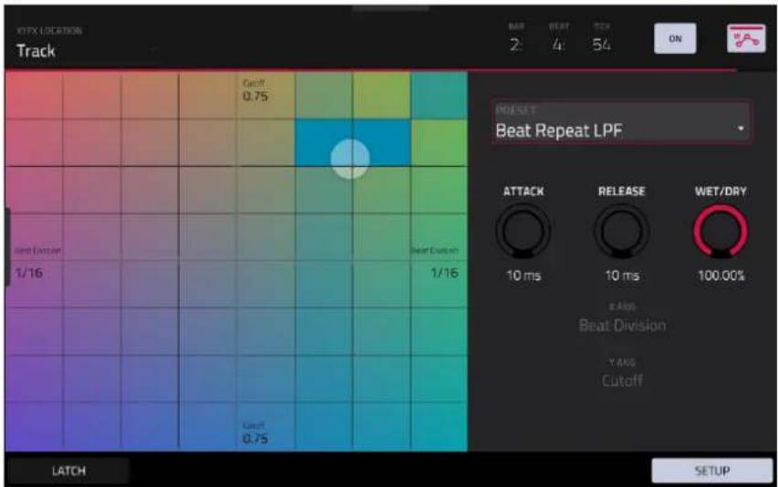
- Press Menu, and then tap XYFX to enter XYFX Mode.
- Tap the XYFX Location field, and select Track. This will add the XY effect to the currently selected track.
- When you first enter this mode in a project, you will be prompted to "load" XYFX to the track. Tap Insert XYFX to do this.
- Tap Setup to show the Setup panel, which controls how the XY pad behaves.
- Double-tap the Preset field, and tap an effect to select it. (These are just the effects available in XYFX Mode, not all MPC effects.) Swipe up or down to view the complete list.
- Tap and drag any of the knobs (Attack, Release, or Wet/Dry) up or down to set their values as desired. Below them, you can see what parameter the X axis and Y axis control.
Note: XYFX uses an envelope to control how quickly the effect crossfades between the dry signal and wet signal. The Attack knob determines how long it takes the completely dry signal to reach the wet signal (determined by the Wet/Dry knob) after you touch the XY pad. The Release knob determines how long it takes the wet signal (determined by the Wet/Dry knob) to return to the completely dry signal after you touch the XY pad.
-
Tap the automation button to cycle through the available automation modes. Make sure the button is red (the Write (W) option).
-
Press Play Start to start recording.
-
As you record, move your finger over the XY pad on the screen. The changes in the sound are being recorded as automation of both the X axis and Y axis parameters.
Tip: While touching the XY pad, tap Latch in the lower-left corner to keep the marker on the XY pad even after you release it. The marker will remain there until you touch another part of the XY pad or until you tap Latch again.
-
When you are done recording, press Stop.
-
Tap the automation button to select the green Read (R) option. This ensures your track uses the automation you just recorded when you play it back.
See Operation > Modes > XYFX Mode to learn more about using this feature.
Creating a Song
As your project grows, you may have multiple sequences of music that you want to piece together into a larger song for exporting. This can be done using Song Mode.
To enter Song Mode, make sure playback is stopped, then press Menu, and then tap Song. Alternatively, press Song (MPC X).

In Song Mode, each of the sequences you've created in this project are assigned to a pad. The sequence playlist is to the left of the pads, showing the song's structure.
As a song plays, it moves through each step of the sequence playlist. Each step contains a sequence you assigned. Each step can be repeated, determined by the value in the Repeat column (the repeat icon; a value of 1 means the sequence will play through only once). The Bars column on the right indicates the length of that sequence.
Each step can be set to play its sequence at an independent tempo, determined by the value in the BPM column.
Important: Each sequence has its own tempo, while the project itself may use a different global tempo. The BPM value for each sequence may be different from the global tempo. As long as playback is set to follow the global tempo, each sequence's individual tempo will be ignored. By default, each project is set to use the sequence tempo. We recommend tapping the SEQ/GBL button at the top of the screen (so the button displays GBL) and entering a global tempo to ensure all sequences use the same tempo.
Tap Insert to insert a step at the current position.
Tap Delete to delete the currently selected step.
To set which sequence plays for a step, tap the step's Sequence field, and then turn the data dial to select a sequence.
To set how many times a sequence repeats, tap the step's Repeat field (next to the sequence name), and then turn the data dial to select a number.
Want to share your new song? Just export it first.

To export a song:
- While in Song Mode, tap Export at the bottom of the screen.
- In the Audio Mixdown screen that appears, do the following:
• Make sure the Start field is set to 1, and set the End field to the last bar of your song.
- Tap the Audio Tail field and turn the data dial to set it to 2 seconds.
- As you'll likely share the song online, tap the mp3 file format option in the lower-left corner.
- Tap Export. Choose where you want to save the song.
To name the song, tap the File Name field, and use the virtual keyboard that appears to enter a new name, and then tap Save to start exporting.
See Operation > Modes > Song Mode to learn more about using this feature.
Operation
This chapter explains the complete features and functions of the MPC operating system. For a breakdown of the hardware controls on your MPC device, see the following Hardware Features section.
Important:
- When the left-most button at the bottom of the screen shows an upward arrow (↑), it means there are additional buttons you can use when you press and hold Shift. Press and hold Shift to show the secondary buttons. Release Shift to return to the previous buttons.
- Many modes shown on the screen have 1–6 buttons at the bottom. Each of these buttons select a different tab in that mode or perform a specific function in that mode. If there are more than six tabs available, use the < and > buttons to scroll between them.


- As an alternative to double-tapping an item on the screen to "enter" it, you can press the data dial.
- When a parameter is highlighted and has a red outline, this means that it is selected. You can then change it by turning the hardware's data dial or using the - / + buttons. If the parameter is a number, double-tap it to show a numeric keypad on the screen to enter a specific value.
General Features
Control Types
This section covers the types of control elements featured on the MPC touchscreen, and details how you can adjust them using the touchscreen or your hardware controls. In descriptions throughout the remainder of this manual, touchscreen controls are primarily referenced, but you can always use the hardware controls described below to adjust each control type.
Knobs
To set the value for a knob, do any of the following:
- Tap and drag the knob up or down.
- Tap the knob to select it, and then use the data dial or -/+ buttons to adjust the value.
- Double-tap the knob to show it in a larger screen. Alternatively, press data dial when the knob is selected.
Tap and drag the larger version that appears, or use the data dial or - / + buttons to adjust the value.
If the knob is bipolar (has positive and negative values with the center as the default position), double-tap the larger version to reset it to the center/0 position.
Tap anywhere else to return to the previous screen.
- Press and hold Shift while turning the data dial to adjust a value by smaller increments.
Parameter Values
To set the value for a parameter, do either of the following:
- Tap the field to select it, and then use the data dial or - / + buttons to adjust the value.
When the value has decimal places, you can sometimes press and hold Shift and then use the data dial or - / + buttons to adjust the value by smaller increments.
- Double-tap the field or hold your finger on it for a second. In the screen that appears, type in a value using the number pad, or use the data dial or the - / + buttons to adjust the value. Alternatively, tap and drag the value up or down.
You can also tap /2 to halve the value or x2 to double it.
To confirm the value and remain on this screen, tap Apply.
To confirm the value and return to the previous screen, tap Do It.
To return to the previous screen, tap the gray area in the upper-left corner of the screen. Unsaved changes made using the number pad will not be applied. All other changes will be saved.

Drop-Down Menus / Lists
To select an option for a drop-down menu, do any of the following:
- Tap the field to select it, and then use the data dial or - / + buttons to select an option.
- Double-tap the field. In the list that appears (examples below), tap the desired option. Alternatively, use the data dial or the - / + buttons to select an option.
In some windows, tap the relevant button at the bottom of the screen to confirm your selection or to cancel without changing anything.


Selectors
Selectors show all available options. One of them is always selected. The selected option is highlighted while the others are dark.
To select an option, tap it.
Buttons
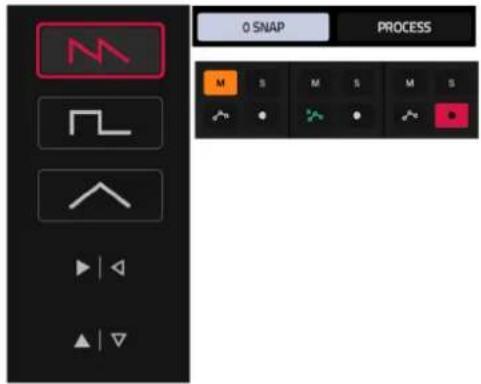
Buttons usually have two states: selected and deselected (active or inactive, respectively). Some may have more than two states.
To switch between or cycle through a button's states, do either of the following:
- Tap it.
- If it is outlined in red (and is not a mute button), use the data dial or -/+ buttons.
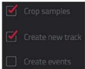
Checkboxes
Checkboxes have two states: checked and unchecked (enabled or disabled, respectively).
To check or uncheck a checkbox, tap it.
Tabs
Some modes have buttons at the bottom of the screen that let you cycle through several similar tabs. For example, you can toggle between Trim and Chop modes in Sample Edit Mode, or cycle between the Samples tabs in Track Edit Mode. With each tap, you will move to the next tab, indicated by the squares below it.
To select a tab, tap it. Each time you tap it, it will select the next tab.

Sliders
To adjust the position of a slider, do any of the following:
- Tap and drag the slider to the desired position.
- Tap the desired position (this works only on some sliders).
- Tap the slider to select it, and then use the data dial or - / + buttons to adjust the position (this works only on some sliders).
- Double-tap the slider, and then tap and drag the larger version that appears, or use the data dial or - / + buttons to adjust the value. Tap anywhere else to return to the previous screen.

bar
| Category | Value | |---|---| | BFCF | 3.0 | | ETEXX | 4.0 | | GAP | 5.0 | | OBB | 6.0 |Envelopes
To set the stages of an envelope, do either of the following:
Tip: Tap the expand-rectangle icon above the envelope to show a close-up view.
- Tap and drag a "handle" of an envelope stage in the desired direction.
- Set the numeric value of an envelope stage by adjusting or entering it as a parameter value (described earlier).


The Envelope tab in Track Edit Mode (Drum Tracks).


line
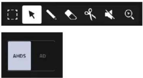
| Label | Value | |-------|-------| | ATTEND | 65 | | ASHARE | -25 | | HOLD | 25% | | DECAV | 81 | | D-SHARE | 9 | | SUSTAIN | 103 |Close-up of an AD-type filter envelope. Close-up of an AHDS-type amp envelope.
Tracks
About Tracks
Each sequence you create within a project is made up of tracks. There are six main types of tracks, each of which determines how the track sounds or for what it is used. A single project can hold up to 128 tracks.
To learn about editing your tracks to your preference, see the Modes > Track Edit Mode chapter.


An Audio track lets you record audio from an external source or by resampling another track to create a sample. See Audio Tracks for more information.

A drum track uses one or more samples as its sound source. It contains (1) a list of samples and (2) the settings for each sample (i.e., pad assignments, loop points, pitch tuning, effects, etc.). Drum tracks are used mostly for creating drum parts and quickly and easily assigning samples to pads. See Drum Tracks for more information.

A keygroup track uses one or more samples as its sound source. It contains (1) a list of samples and (2) the settings for each sample (i.e., pitch tuning, effects, etc.). Keygroup tracks are used to play samples chromatically with a MIDI keyboard or the MPC pads. See Keygroup Tracks for more information.

A plugin track contains an instance of a plugin through which you can send your track's MIDI data. See Plugin Tracks for more information.

A MIDI track lets you send your track's MIDI data to an external MIDI device like a synth or drum machine. See MIDI Tracks for more information.

A CV track lets you send your track's MIDI data to an external device that uses control voltage (CV), like a synth. See CV Tracks for more information.
To create a new track:
- Press Main to open Main Mode, or select Main from the Menu.
- Tap the New Track button at the bottom of the screen.
- A window will appear where you can select the track type. Tap to select a track type, which will be instantly added to your project.
Alternatively, tap the Advanced button at the bottom of the screen. In this window, use the Type field to select the track type. You can also use the Number of Tracks field to add multiple tracks of the selected type.
For Audio Tracks, you can also adjust the following options:
Use the Input field to select which inputs the audio track will use.
Check the Ascending box to determine if the channel numbers of the input sources will ascend across the new audio tracks you create. When checked, the first new audio track will use the input source you set above (e.g., Input 1), the second new audio track will use the next input source (e.g., Input 2), etc. When unchecked, all of the new audio tracks you create in this instance will use the same input source. This feature is relevant only if you are creating more than one new audio track (determined by Number of Tracks below).
Check the Record Enable box to set the new track to be automatically record enabled.
Use the Input Monitoring field to set the monitoring behavior: Off, On, Auto, or Merge.
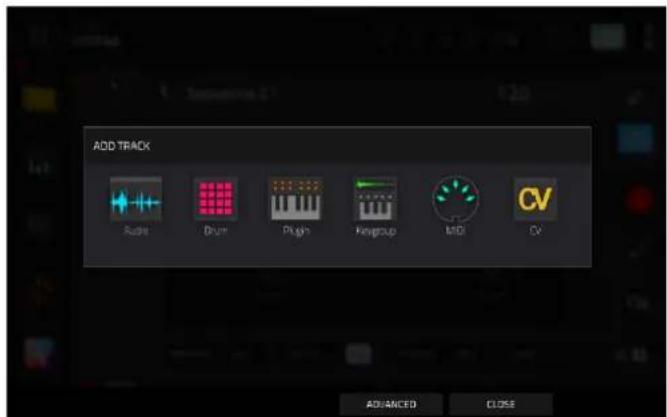
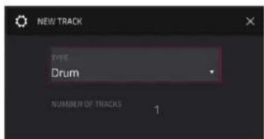

To change a track from one type to another, tap the track type icon/track number in the Track Section of Main Mode. A selector will appear where you can select from the five remaining track types.

To access the Track Settings window, described for each track type below, do either of the following:
- Tap and hold on the Track Name in the Track Section of Main Mode.
- Double-tap the track header in the Channel Mixer or Arrange Mode.
Audio Tracks


Settings:
Tap the track name field to rename the track. Use the virtual keyboard that appears to enter a new name, and then tap Do It to confirm or the gray bar at the top of the screen to cancel.
Use the Position field to change the location of the track, moving the other tracks in relation.
Use the Rec Arm field to arm (On) or disarm (Off) the track for recording.
Use the Monitor field to set the monitoring behavior of the track:
When set to Off, you will never hear any incoming audio.
When set to In, you will hear incoming audio whether or not the track is record-enabled.
When set to Auto, you will hear incoming audio while the track is record-enabled only.
When set to Merge, the track's input is always monitored, and you will hear playback of recorded events.
Use the Audio Input field to set the input source for the track.
Use the Audio Output field to set the output destination for the track.
Use the Color field to change the track color.
Tap Delete Track at the bottom of the screen to remove the track.
Tap Reset Strip at the bottom of the screen to reset all mixer settings for the track.
Tap the -/+ buttons at the bottom of the screen to move to the previous or next track.
Drum Tracks


Settings:
Tap the track name field to rename the track. Use the virtual keyboard that appears to enter a new name, and then tap Do It to confirm or the gray bar at the top of the screen to cancel.
Use the Position field to change the location of the track, moving the other tracks in relation.
Use the Rec Arm field to arm (On) or disarm (Off) the track for recording.
Use the MIDI Routing fields to edit the MIDI routing for the track:
MIDI Input Port: Select the MIDI port from which to receive MIDI data. When set to All Ports, the track will receive all incoming MIDI Data from any connected port. To view and edit the available ports, go to Preferences > MIDI / Sync.
MIDI Input Channel: Sets the MIDI Channel from which to receive MIDI data. Select Any to receive from any MIDI channel, or select 1–16.
MIDI Send: Sets where the MIDI data is sent. You can use this to send the MIDI data from one track to another track.
Use the MIDI Monitor field to set the monitoring behavior of the track:
Off: The track's MIDI input is not monitored, and playback of recorded events will be heard. This setting is useful when using keyboards with Local Control active.
In: The track's MIDI input is always monitored regardless of the track's Record Arm state, and playback from recorded events will not be heard.
Auto: The track's MIDI input is monitored when the track is record armed, and playback of recorded events will be heard.
Merge: The track's MIDI input is always monitored, and playback of recorded events will be heard.
Use the Color field to change the track color.
Tap Delete Track at the bottom of the screen to remove the track.
Tap Reset Strip at the bottom of the screen to reset all mixer settings for the track.
Tap the -/+ buttons at the bottom of the screen to move to the previous or next track.
To load a kit into a drum track:
- Press Menu and tap Browser to show the Browser.
- Tap the Drums content icon on the left side of the screen to display the factory kits, or navigate to another file location and use the four-squares icon above the file list to show only kit files. (See Modes > Browser to learn more about using the Browser specifically.)
- Find and select a kit, and then tap Load to load it to the track.
To load a sample into a drum track:
- Press Menu and tap Browser to show the Browser. If you have an empty pad selected, you can also tap the Browse button in the Track area to open the Browser.
- Find and select a sample, and then tap Load to load it to the track. Repeat this for any other samples you want to load into the project. (See Modes > Browser to learn more about using the Browser specifically.)
- Tap Sample Assign to view the pads and project's sample pool.
- Press or tap a pad to select it. The pad will be lit green.
- In the Sample Pool list, double-tap a sample or press the data dial to assign it to the pad. Alternatively, tap and drag from the Sample Pool list directly onto a pad to assign it.
To clear the assigned sample from a selected pad, tap Clear Pad.
To assign samples to additional pads, repeat Steps 3–4.
Tip: Remember that a drum track has 128 pads total—16 pads across eight banks.
![Trap-Kit-Default Bank B [Internal] The Vault 2 SAMPLE POOL Trap-HilHat-Hat 1 Trap-HilHat-Hat 2 Trap-Park-Kick Trap-Park-Chord Trap-Perc-Perc Trap-Perc-Tom Trap-Vocal-Vox 1 Trap-Vocal-Vox 2 Trap-Cymbal-Cym Trap-Kick-Kick Samples Diaminos My Files Search MIME (0072 here) Acoustic-Cymbal-Ac1 Crsh 1.WAV Acoustic-Cymbal-Ac1 Crsh 2.WAV Acoustic-Cymbal-AC1 Rd Bell.WAV Acoustic-Cymbal-AC1 Rd Bow.WAV Acoustic-Cymbal-Ac2 Crsh 1.WAV Acoustic-Cymbal-Ac2 Crsh 2.WAV Acoustic-Cymbal-Ac2 Rd Bell.WAV SAMPLE ASSIGN AUDITION CLEAR PRO SAMPLE ASSO! AUDITION LOAD TO POOL LOAD](/content/2026/05/883354/images/20e5bc678abff374713a4ed538354f7781f103c1bb7c9ad8f23e8d8b8978480d.jpg)
Alternatively, assign samples in a drum track in Track Edit Mode in one of these two ways:
- Press Menu, and then tap Track Edit to enter Track Edit Mode.
- Tap the Samples tab. This lets you view the samples assigned to all eight layers of the current pad as well as tuning and level parameters for each layer.
- Tap a pad to select it (and play its assigned samples, if any).
- Tap one of the Layer 1-8 fields under the sample waveform to select a layer. Tap the Sample field, and then use the data dial or - / + buttons to select a sample. Alternatively, double-tap the field for a layer, and then tap a sample to select it.

- Press Menu, and then tap Track Edit to enter Track Edit Mode.
- Tap the Samples tab until one of the last three pages are selected. This lets you view the samples assigned to all eight layers of the current pad as well as other parameters for each layer depending on the page.
- Tap a pad to select it (and play its assigned samples, if any).
- Tap the Layer 1-4/5-8 button to toggle between groups of layers. Tap a Sample field, and then use the data dial or - / + buttons to select a sample. Alternatively, double-tap the field for a layer, and then tap a sample to select it.

Keygroup Tracks

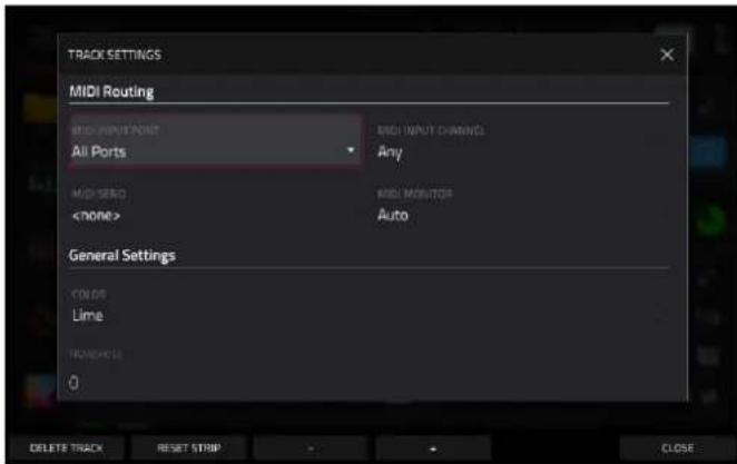
Settings:
Tap the track name field to rename the track. Use the virtual keyboard that appears to enter a new name, and then tap Do It to confirm or the gray bar at the top of the screen to cancel.
Use the Position field to change the location of the track, moving the other tracks in relation.
Use the Rec Arm field to arm (On) or disarm (Off) the track for recording.
Use the MIDI Routing fields to edit the MIDI routing for the track:
MIDI Input Port: Select the MIDI port from which to receive MIDI data. When set to All Ports, the track will receive all incoming MIDI Data from any connected port. To view and edit the available ports, go to Preferences > MIDI / Sync.
MIDI Input Channel: Sets the MIDI Channel from which to receive MIDI data. Select Any to receive from any MIDI channel, or select 1–16.
MIDI Send: Sets where the MIDI data is sent. You can use this to send the MIDI data from one track to another track.
Use the MIDI Monitor field to set the monitoring behavior of the track:
Off: The track's MIDI input is not monitored, and playback of recorded events will be heard. This setting is useful when using keyboards with Local Control active.
In: The track's MIDI input is always monitored regardless of the track's Record Arm state, and playback from recorded events will not be heard.
Auto: The track's MIDI input is monitored when the track is record armed, and playback of recorded events will be heard.
Merge: The track's MIDI input is always monitored, and playback of recorded events will be heard.
Use the Color field to change the track color.
Use the Transpose field to adjust the transposition amount of the track.
Tap Delete Track at the bottom of the screen to remove the track.
Tap Reset Strip at the bottom of the screen to reset all mixer settings for the track.
Tap the -/+ buttons at the bottom of the screen to move to the previous or next track.


To assign samples in a keygroup track:
- Press Menu, and then tap Track Edit to enter Track Edit Mode.
- Tap the Samples tab. This lets you view the samples assigned to all eight layers of the current keygroup as well as other parameters for each layer depending on the selected page.
- Use the Number of KG field to set the number of keygroups in the track (1–128).
- Use the Keygroup field to select a keygroup.
- Tap the Layer 1-4/5-8 button to toggle between groups of layers. Tap a Sample field, and then use the data dial or - / + buttons to select a sample. Tap the field for a layer, and then use the data dial or - / + buttons to select a sample. Alternatively, double-tap the field for a layer, and then tap a sample to select it.
To create complex keygroup track, you can add more keygroups (up to 128). This is useful when working with multi-samples (e.g., when programming a real piano).
Tip: Remember that a keygroup track offers up to 128 keygroups, and each keygroup can hold up to eight samples (Layers 1–8). This is a total of 1024 samples.
Plugin Tracks
To learn more about the plugins included with MPC, see Appendix > Plugins.

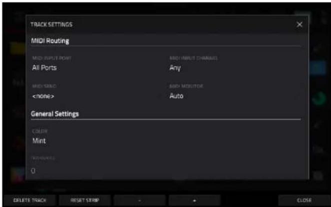
Settings:
Tap the track name field to rename the track. Use the virtual keyboard that appears to enter a new name, and then tap Do It to confirm or the gray bar at the top of the screen to cancel.
Use the Position field to change the location of the track, moving the other tracks in relation.
Use the Plugin field to open the Plugin window to select a plugin for the track.
Tap Type or Manufacturer to sort your plugins by type or maker.
Tap Select to select the plugin, or tap Close to cancel.
Use the Preset field to select a Preset from the loaded plugin.
Use the Rec Arm field to arm (On) or disarm (Off) the track for recording.
Use the MIDI Routing fields to edit the MIDI routing for the track:
MIDI Input Port: Select the MIDI port from which to receive MIDI data. When set to All Ports, the track will receive all incoming MIDI Data from any connected port. To view and edit the available ports, go to Preferences > MIDI / Sync.
MIDI Input Channel: Sets the MIDI Channel from which to receive MIDI data. Select Any to receive from any MIDI channel, or select 1–16.
MIDI Send: Sets where the MIDI data is sent. You can use this to send the MIDI data from one track to another track.
Use the MIDI Monitor field to set the monitoring behavior of the track:
Off: The track's MIDI input is not monitored, and playback of recorded events will be heard. This setting is useful when using keyboards with Local Control active.
In: The track's MIDI input is always monitored regardless of the track's Record Arm state, and playback from recorded events will not be heard.
Auto: The track's MIDI input is monitored when the track is record armed, and playback of recorded events will be heard.
Merge: The track's MIDI input is always monitored, and playback of recorded events will be heard.
Use the Color field to change the track color.
Use the Transpose field to adjust the transposition amount of the track.
Tap Delete Track at the bottom of the screen to remove the track.
Tap Reset Strip at the bottom of the screen to reset all mixer settings for the track.
Tap the -/+ buttons at the bottom of the screen to move to the previous or next track.
MIDI Tracks

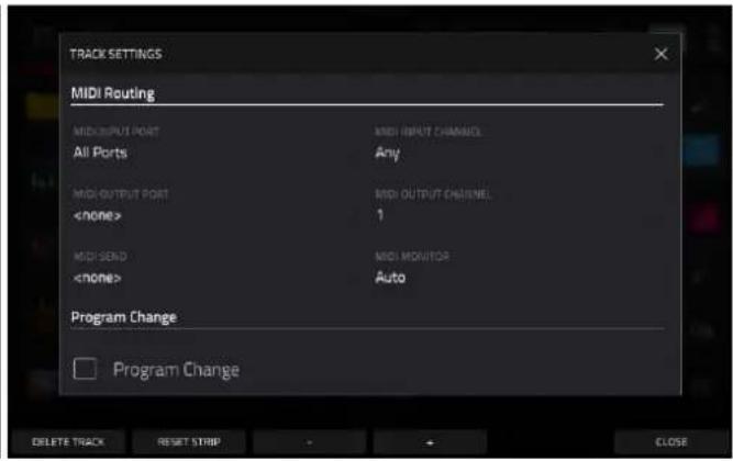
Settings:
Tap the track name field to rename the track. Use the virtual keyboard that appears to enter a new name, and then tap Do It to confirm or the gray bar at the top of the screen to cancel.
Use the Position field to change the location of the track, moving the other tracks in relation.
Use the Rec Arm field to arm (On) or disarm (Off) the track for recording.
Use the MIDI Routing fields to edit the MIDI routing for the track:
MIDI Input Port: Select the MIDI port from which to receive MIDI data. When set to All Ports, the track will receive all incoming MIDI Data from any connected port. To view and edit the available ports, go to Preferences > MIDI / Sync.
MIDI Input Channel: Sets the MIDI Channel from which to receive MIDI data. Select Any to receive from any MIDI channel, or select 1–16.
MIDI Output Port: Select the MIDI port to send MIDI data to. To view and edit the available ports, go to Preferences > MIDI / Sync.
MIDI Output Channel: Sets the MIDI Channel to send MIDI data to. Select Any to receive from any MIDI channel, or select 1–16.
MIDI Send: Sets where the MIDI data is sent. You can use this to send the MIDI data from one track to another track.
Use the MIDI Monitor field to set the monitoring behavior of the track:
Off: The track's MIDI input is not monitored, and playback of recorded events will be heard. This setting is useful when using keyboards with Local Control active.
In: The track's MIDI input is always monitored regardless of the track's Record Arm state, and playback from recorded events will not be heard.
Auto: The track's MIDI input is monitored when the track is record armed, and playback of recorded events will be heard.
Merge: The track's MIDI input is always monitored, and playback of recorded events will be heard.
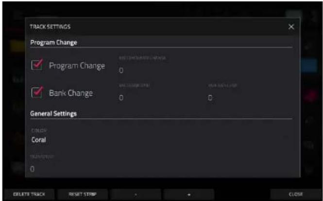
To select a MIDI program change value for the track to send, check the Program Change box to enable program changes, and then double-tap the MIDI Program Change field. Use the number pad that appears to enter a value from 1–127, then tap Do It. The track will send this value when played. Once enabled, you can also select a MIDI bank change value by checking the Bank Change box to enable bank changes, and then use the MIDI Bank MSB and MIDI Bank LSB fields to set the bank change values.
Use the Color field to change the track color.
Use the Transpose field to adjust the transposition amount of the track.
Tap Delete Track at the bottom of the screen to remove the track.
Tap Reset Strip at the bottom of the screen to reset all mixer settings for the track.
Tap the -/+ buttons at the bottom of the screen to move to the previous or next track.
CV Tracks

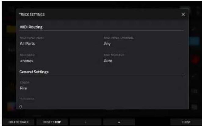
Settings:
Tap the track name field to rename the track. Use the virtual keyboard that appears to enter a new name, and then tap Do It to confirm or the gray bar at the top of the screen to cancel.
Use the Position field to change the location of the track, moving the other tracks in relation.
Use the Rec Arm field to arm (On) or disarm (Off) the track for recording.
Use the Type field to select Melodic or Drum CV track operation. Melodic CV tracks behave the same as previous MPC versions. Drum CV tracks can be used to configure any pad to output on any CV port.
When Melodic type is selected, there are five additional settings to configure for a CV track: the CV Port, the Gate Port, the modulation wheel port (Mod Wheel Port), Velocity Port and Note Priority. Tap each field and use the data dial or -/+ buttons to edit the setting.
When Drum type is selected, tap the Edit Map button to assign each pad to a specific CV port and data type.
Use the MIDI Routing fields to edit the MIDI routing for the track:
MIDI Input Port: Select the MIDI port from which to receive MIDI data. When set to All Ports, the track will receive all incoming MIDI Data from any connected port. To view and edit the available ports, go to Preferences > MIDI / Sync.
MIDI Input Channel: Sets the MIDI Channel from which to receive MIDI data. Select Any to receive from any MIDI channel, or select 1–16.
MIDI Send: Sets where the MIDI data is sent. You can use this to send the MIDI data from one track to another track.
Use the MIDI Monitor field to set the monitoring behavior of the track:
Off: The track's MIDI input is not monitored, and playback of recorded events will be heard. This setting is useful when using keyboards with Local Control active.
In: The track's MIDI input is always monitored regardless of the track's Record Arm state, and playback from recorded events will not be heard.
Auto: The track's MIDI input is monitored when the track is record armed, and playback of recorded events will be heard.
Merge: The track's MIDI input is always monitored, and playback of recorded events will be heard.
Use the Color field to change the track color.
Use the Transpose field to adjust the transposition amount of the track.
Tap Delete Track at the bottom of the screen to remove the track.
Tap Reset Strip at the bottom of the screen to reset all mixer settings for the track.
Tap the -/+ buttons at the bottom of the screen to move to the previous or next track.
Menu
The Menu displays the available modes in MPC, as well as project information, hardware information, preferences, save and load options, and more.
To open the Menu, press Menu, or tap the icon in the upper-left corner of the screen while in Main Mode.
When viewing the Menu, do any of the following:
To enter a mode, tap it.
To return to the previous mode, tap ← in the upper-left corner, or press Menu again.
To change menu pages, tap the < or > arrows.
Tap New Project to open a new project.
Tap Save to open the Save Window.
Tap Project to open the Project window.
Tap Preferences to open the Preferences menu.
To rearrange the menu layout, tap and drag a mode icon to the desired location. All other mode icons will shift to accommodate the new positioning. The five modes on the left side are also available to access in most screens by swiping the black touch handle to the right from the left edge of the touchscreen. Tap the three-dots icon next to the Sync setting and then tap Reset Mode Menu to revert all layout changes.

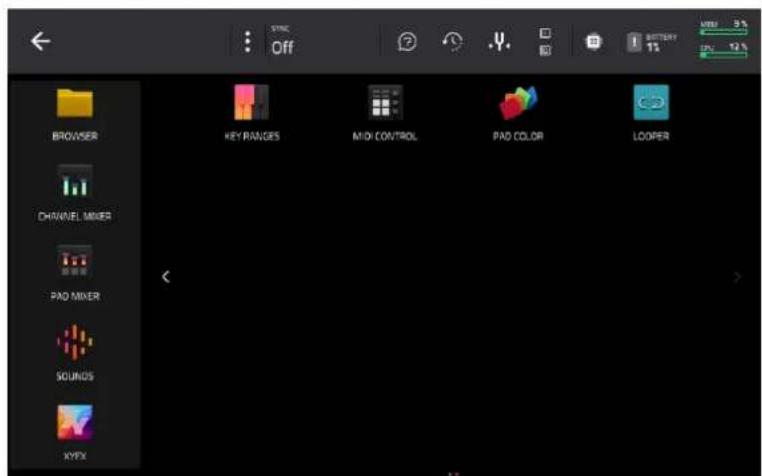
Click a part of the screen above to skip directly to that part of this user guide.
Toolbar
Sync
Tap the Sync field (in the center of the top of the screen) and then turn the data dial or use the -/+ buttons to set whether your MPC hardware receives MIDI Clock information (MIDI Clock), MIDI Time Code information (MTC), communication from Ableton Link, or none of these (Off). Alternatively, double-tap Sync and tap the desired option to select it.
This is the same setting as the Receive menu in the Preferences > MIDI / Sync tab.
Note: Ableton Link is a technology that synchronizes beat, phase, and tempo of Ableton Live and Ableton Link-enabled applications over a wireless or wired network. See Preferences > Wi-Fi or Preferences > Ethernet to learn how to connect to a network.
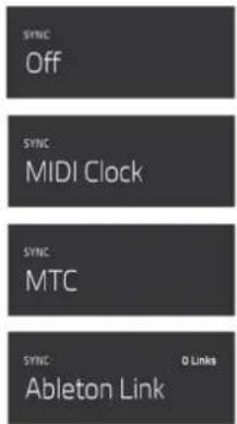
Help
Tap the ? icon to open the Help window. Scan the QR code that appears to open this User Guide.
Tap Close or the X to close the Help window.

Undo History
Tap the clock icon at the top of the screen to open the Undo History window. In the Undo History window, you can view a list of recent actions along with a detail about the action if applicable.
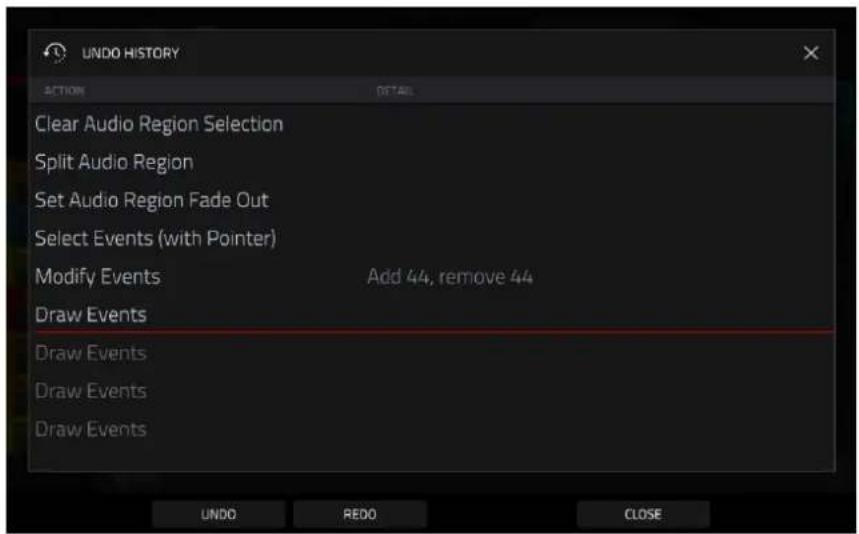
Tap Undo to undo an action.
Tap Redo to redo an action.
Alternatively, tap and drag the red line in the action list to quickly undo or redo multiple actions. Actions below the red line in grey have been undone.
Tap Close or the X to close the Undo History window.
Tuner
Tap the tuning fork at the top of the screen to open the built-in tuner. The tuner allows you to easily tune any connected audio sources such as guitars, basses, synth modules, and other pitched instruments.
To tune your instrument, play a note and use the indicator to adjust your instrument to the correct pitch.
Use the Input Channel field to select the input for the instrument you would like to tune.
Use the Frequency of A field to set the base tuning frequency.
Tap Close, the X in the upper-right corner, or anywhere outside the window to close the tuner screen.
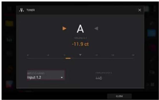
MIDI Monitor
Tap the I/O icons to open MPC's MIDI monitor. You can use this to view incoming and outgoing MIDI data from devices connected to your MPC hardware.
Tap the In button to view incoming MIDI data.
Tap the Out button to view outgoing MIDI data.
Tap the Clear button to clear the list of MIDI data.
Tap the Close button or the X to close the MIDI Monitor.
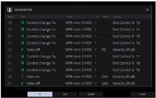
Mode
Tap this icon to switch MPC to Controller Mode. In the screen that appears, select whether you want to continue to Controller Mode or Cancel and return to your current mode and project. It is recommended to save your project before switching to Computer Mode since you cannot freely switch between Standalone and Controller Modes without also closing your current project.

System Resources
Tap one of these icons to show the System Resources window for MPC.

The indicators in this window show current usage statistics:
Battery: If you are using MPC Live/Live II, the first indicator shows the current battery life as a percentage. If these are connected to power, it will also show the charging status. (See Battery Usage to learn more about MPC Live/Live II's internal battery.)
CPU: The CPU indicator shows the current CPU as a percentage.
RAM Usage: The Mem indicator shows your MPC hardware's current RAM usage.
Important: If you encounter a warning that there is not enough memory to complete an action while using your MPC hardware, do the following to make more memory available:
Make sure all audio tracks in your project are not record-armed.
Remove unused samples from your project's sample pool that were there before the warning appeared, and discard unused regions of samples that have been loaded within the project.
If you are still seeing the warning, do the following:
- Manually undo the last action you performed before seeing the warning (you may not be able to use the Undo button for this due to how the undo history is stored in RAM).
- Save your project.
-
Do one of the following, and then load your saved project again.
-
Open the Menu, and then tap New Project at the bottom of the screen.
• Power your MPC hardware off and then on again. - Press Menu and then tap the gear icon to open the Preferences. In the Preferences, tap Reset at the bottom of the screen, tap OK, and then tap Restart to reset the Preferences.
- Enter Controller Mode and then reenter Standalone Mode.
Important: Although you can load multiple files at once, any samples you load into a project will be automatically converted to full-quality uncompressed audio files, so they may use more storage space than they do on your external storage device. If you are unable to load multiple files at once due to this, select fewer files and try again.
Drives: The Drives indicator shows the available storage space on any detected external storage devices or the internal drive of your MPC hardware.
To delete samples from the project (to create more free RAM space for sampling time, audio recording, etc.), tap Purge. In the screen that appears, tap Unused Samples to delete all unused samples from the project, tap All Samples to delete all samples from the project (from all tracks, sequences, and audio or MIDI tracks), or tap Cancel to return to the previous screen.
To close the System Resources window, tap OK, the X in the upper-right corner, or anywhere outside the window.
Project

To open the Project window, tap the Project button at the bottom of the Menu. The Project window shows an overview of all samples and tracks in the current project.
Tap Purge to delete samples from the project (to create more free RAM space for sampling time, audio recording, etc.). In the screen that appears, tap Unused Samples to delete all unused samples from the project, tap All Samples to delete all samples from the project (from all kits and audio or MIDI tracks), or tap Cancel to return to the previous screen. Alternatively, tap to select a sample and then tap Delete at the bottom of the screen.
Tap Memory and Streaming to show or hide files in memory or streaming from disk. Before doing this, you must first enable Disk Streaming by going to Menu > Preferences > Audio/Export and checking the Enable Disk Streaming box. Disk streaming allows audio files to be streamed from a disk drive rather than from memory.
Note: Disk streaming relies on the performance of the disk you are streaming from. For best operation, it is recommended to use an SSD (solid-state drive) connected to your MPC's internal SATA port (if available). Once you have saved a project to your SSD, your files will stream from that location. For an unsaved project, MPC uses a temporary file location from which to stream audio files. Go to Menu > Preferences > Project Load/Save and set the Temporary File Location to your SSD for best results.
To change a sample from streaming from memory to streaming from disk, tap and hold on a sample name in the Project list, and then select Stream From Disk in the menu that appears. A sample's streaming or memory state will be saved and recalled with your project.
Note: Using streamed samples with Drum and Keygroup tracks may cause performance issues when triggering multiple samples or retriggering at high rates.
If a project is too large to be loaded into memory, your MPC hardware will load the project and display the missing samples in the Project window with a waveform with a red minus icon. Once enough memory has been freed up, the missing samples can then be loaded from the Project window. Tap and hold on the sample name and then select Load To Memory from the menu that appears.
Tap a sample or select it using the data dial or -/+ buttons to preview it.
Tap Save at the bottom of the screen to save the selected sample.
Tap Rename at the bottom of the screen to rename the selected sample. Use the keyboard that appears to enter a name and then tap Do It to confirm.
Tap Edit at the bottom of the screen to open Sample Edit mode to edit the selected sample.
Tap Audition at the bottom of the screen to open the Audition settings.
Tap Auto to enable or disable automatic audition when a sound is selected.
Tap and drag the level slider up or down to set the audition volume level.
Tap Sync to enable or disable auditioning samples at the beginning of the next bar of the sequence when playback is active.
Tap Warp to enable or disable samples with an embedded tempo to be warped to the project tempo. Samples with no embedded tempo or externally-embedded tempo will not be affected by this setting.
Tap the Audition icon once more to hide the window.
Preferences
To open the Preferences, tap the Preferences at the bottom of the Menu.
To return to the Menu, tap the ← icon in the upper-left corner. Changes to the Preferences are saved automatically.
To restore your MPC hardware's default settings, tap Reset Preferences. In the screen that appears, tap OK to continue or Cancel to return to the Preferences. In the next window, tap Save to save your current project before restoring the default settings; tap Cancel to return to the Preferences; or tap Don't Save to restore the default settings without saving your current project.

Info
This screen shows current information about your MPC hardware: its current firmware version, which includes its standalone operating system (MPC Firmware); its hardware Serial Number; and its current firmware for the Control Surface.
Tap Update to update your MPC.
Select Online Update to automatically download and install the latest update (you must enable a network connection for this to work).
Select USB Drive Update to update from a file on a connected USB drive.
Select Switch to Update Mode to connect your MPC to your computer for updating. In the screen that appears, tap Save to save your current project before entering Update Mode; tap Cancel to return to the Preferences; or tap Don't Save to enter Update Mode without saving your current project.
Tap Reset Preferences to reset all MPC preferences to their default settings.
To view legal information relevant to MPC, press and hold Shift and tap Legal Info. For complete legal information, visit akaipro.com/product-legal.
To view additional version information, press and hold Shift and tap Version Info.
Activations
The settings on this screen allow you to sign in to your inMusic Profile to activate purchased plugin licenses.
- First, make sure you are connected to a Wi-Fi or Ethernet network.
- In the Activate Plugins menu, tap the Log In button to log into your inMusic Profile. You can scan the QR code with a mobile device or open the URL shown on the page in a browser of your choice. Enter the code shown on your device and log into your account. If you do not already have an account, you will be prompted to create one.
- Once you have been logged in, you can try out plugin instruments through a free trial, or activate your purchases.
To start a trial, tap the Get Trial button next to the desired plugin.
To register a purchase, use the Enter Serial field to enter your serial number and then tap Register.
To refresh the page with your latest purchases or activations, tap Refresh.
To activate a plugin on your device, tap the Activate button next to its name. Tap Deactivate to remove the plugin activation from your device.
To download a purchase to your device, first tap the Change button at the bottom of the touchscreen to select a Content Download Drive. This can be the internal storage drive or a connected SATA drive, USB drive, or SD card. Then, tap the download icon to begin downloading the plugin to your drive. The download icon will change to show the installation progress. Once the process is complete, you can use your plugin with standalone MPC.
To log out of your account, tap Log Out.
Wi-Fi
The settings on this screen will determine how your MPC hardware's wireless connection works, so you can use Ableton Link, a technology that synchronizes beat, phase, and tempo of Ableton Live and Ableton Link-enabled applications over a wireless or wired network.
Tap the On/Off selector to activate or deactivate wireless connectivity on your MPC hardware. The available wireless networks will appear in the panel below it.
Tap the desired wireless network to select it, then tap Connect to connect to it. If the Wi-Fi network is password-protected, use the virtual keyboard that appears to enter the correct password to connect to it. Tap Show to display the password as you type it.
To view the information of a selected wireless network, press and hold Shift and tap Info. The Network Information window that appears will show the network name, IPv4/IPv6 address (including the subnet mask and gateway), type of security, and signal strength (as a percentage).
To disconnect from a connected wireless network, select it and then tap Disconnect.
To clear the connection information (e.g., the password) from a selected wireless network, select it and then tap Forget.
Ethernet
The settings on this screen will determine how your MPC hardware connects to a wired network using a USB-to-Ethernet adapter or Ethernet cable (MPC One, MPC Live II, MPC Key 61 only). This allows you to maintain a tighter network connection when using Ableton Link or the Akai Network Driver. These settings are available only for MPC X, MPC X SE, MPC Live, MPC Live II, MPC One, MPC One+, MPC Key 61, and MPC Key 37 when used in Standalone Mode.
To activate or deactivate Ethernet connectivity on your MPC hardware, tap the Enabled box.
To determine how your MPC hardware connects to the network, use the Address Method dropdown. Select Automatic to have your MPC hardware set the Ethernet connection, or Manual to set it yourself.
When setting the Ethernet connection manually, tap the IP Address, Subnet Mask, Gateway, and DNS fields to input the values.
Bluetooth
The settings on this screen will determine how your MPC hardware's Bluetooth connection works, so you can use Bluetooth MIDI controllers (e.g., LPD8 Wireless or LPK25 Wireless) or a Bluetooth computer keyboard with it. These settings are available only for MPC X, MPC X SE, MPC Live, MPC Live II, MPC One+, MPC Key 61, and MPC Key 37 when used in Standalone Mode.
To activate or deactivate Bluetooth connectivity on your MPC hardware, tap the On/Off selector. The available Bluetooth devices will appear in the panel below it under Available Devices. The Bluetooth devices that have already paired to your MPC hardware will appear under Paired Devices.
To select a Bluetooth device, tap it.
To pair a selected Bluetooth device (in the Available Devices section), tap Pair.
To connect to a selected Bluetooth device (in the Paired Devices section), tap Connect.
To disconnect from a connected Bluetooth device (in the Paired Devices section), tap Disconnect.
To return an available Bluetooth device to its original state, tap Remove.
Audio Device
The settings on this screen allow you to set up an external USB and Linux class-compliant audio interface for use with your MPC hardware. Audio devices must also be set to 44.1 kHz sample rate and 128 sample buffer size.
Note: If you are unsure of your audio interface's compatibility, check with the original equipment manufacturer for more information.
Audio Device: This determines whether you are using the Internal sound device, or a selected class-compliant audio interface connected to your MPC hardware.
32 Inputs/Outputs: Check this box to enable use of up to 32 simultaneous inputs and outputs.
Note: Increasing the number of simultaneous inputs and outputs will also increase CPU overhead.
Audio/Export
The settings on this screen determine the settings for audio, recording, and exporting.
Enable Disk Streaming: This determines whether disk streaming is enabled or disabled. MPC will require a restart after disk streaming is enabled or disabled, which may require you to save or discard changes to the current project. Once enabled, a sample can be set to stream from disk or memory using the Project window. By default, Drum and Keygroup samples are loaded into memory, as this works better for on-demand, rapid triggering of multiple, simultaneous voices.
Note: Disk streaming relies on the performance of the disk you are streaming from. For best operation, it is recommended to use an SSD (solid-state drive) connected to your MPC hardware's internal SATA port, if available. Once you have saved a project to your SSD, your files will stream from that location. For an unsaved project, your MPC hardware uses a temporary file location from which to stream audio files. Go to Preferences > Project Load/Save and set the Temporary File Location to your SSD for best results.
Recording Bit Depth: This determines the bit depth of recorded audio.
Bounce/Extract Bit Depth: This determines the bit depth of audio bounced or extracted: 16-bit or 24-bit.
Audio Export: This determines what part of the sequence is exported when you click the Export Audio icon.
Track: When this is selected, Export Audio will export the currently shown track in the current sequence.
Main: When this is selected, Export Audio will export all tracks in that sequence that use programs routed to main outputs.
Audio Tail Length: This determines the length of an audio tail (silence) that will be applied to the exported audio file. When set to 0, the audio file will not have any additional audio tail.
Include Track Volume/Pan Settings: When enabled, the exported audio or MIDI file will include its volume and pan settings. When disabled, the volume and pan settings will be set to 0 dB and center (C), respectively.
Bypass Track Effects Plugins: When enabled, the exported audio or MIDI file will include any third-party effect plugins that are used with it, but those effects will be bypassed (deactivated). When disabled, those effects will be activated.
Default Audio Warp Algorithm: This determines the default time-stretching algorithm, which determines how a sample is “warped” when you adjust the length of a sample without changing its pitch (e.g., the Warp function in Audio Region Edit Mode for audio tracks or in Track Edit Mode for Drum/Keygroup tracks). Select Pro Ten or Repitch. When using Repitch, warping an audio sample will adjust its pitch to synchronize it with the MPC tempo. You can override the default algorithm by selecting another option in the Samples Tab or Track Edit Mode or by changing the algorithm in Grid View.
Note: Warp algorithms can be very CPU-intensive, and can result in audio drop-outs during playback if used too freely. Be mindful of how (and how often) you use the warp function.
Audio Track Auto Warp: This determines how recorded audio track regions are warped. When set to On, any audio track region that you record will be warped automatically to match the current project tempo. You can then adjust the project tempo while the audio track region remains in time.
Note: When you record an audio file, the current project tempo will be embedded with it. This information is stored within the sample file when you save the project. When you warp an audio track region, the warping algorithm uses this project tempo and the current value in the BPM field to generate the “stretch factor.”
BPM Auto Detection: This enables automatic detection of BPM from loaded samples.
BPM Detection Range: This defines the range of detectable BPM values when you use any automatic BPM detection function in the software or when you press the Tap button to enter a new tempo.
MIDI / Sync
The settings on this screen determine how your MPC hardware uses and synchronizes with connected USB and MIDI devices.
Input Ports: This displays all available MIDI input ports in a list. Double-tap the keyboard icon to rename a port to a custom name. When Global is enabled, MIDI data from this port will always go to the current track. When Control is enabled, MIDI data from this port will be sent to MIDI Learn. When Track is enabled, this MIDI port will appear in the list of available MIDI Inputs. Click the reset arrow to reset the MDI Port settings.
Output Ports: This displays all available MIDI output ports in a list. Double-tap the keyboard icon to rename a port to a custom name. When Sync is enabled, the MIDI output port will send MIDI sync messages according to the type set under Sync Send, below. When Track is enabled, this MIDI port will appear in the list of available track MIDI outputs. Click the reset arrow to reset the MDI Port settings.
Enable MIDI Ports When Discovered: When enabled, any time a MIDI device is plugged in the Track option is automatically enabled so the ports can be selected as an available MIDI input or output.
MIDI Control Mode Output: This determines which MIDI port the MPC hardware is using to send MIDI messages to external MIDI devices.
Receive: This determines whether your MPC hardware receives MIDI Clock information (MIDI Clock), MIDI Time Code information (MIDI Time Code (MTC)), communication from Ableton Link (Ableton Link), or none of these (Off).
Important: Audio recording is disabled when receiving MIDI Clock sync. Use MIDI Time Code to record audio while receiving MIDI sync.
Ableton Start/Stop Sync: When enabled, this allows devices connected with Ableton Link to share start/stop commands.
Receive MMC: When enabled, your MPC hardware will be able to receive MIDI Machine Control (MMC) information. When disabled, your MPC hardware will not receive this information. See Appendix > MIDI Machine Control (MMC) to learn about this.
Send: This determines whether your MPC hardware sends MIDI Clock information (MIDI Clock), MIDI Time Code information (MIDI Time Code (MTC)), or neither (Off).
Send MMC: When enabled, your MPC hardware will be able to send MIDI Machine Control (MMC) information. When disabled, your MPC hardware will not send this information. See Appendix > MIDI Machine Control (MMC) to learn about this.
MTC Frame Rate: This determines the frame rate used by MIDI Time Code (MTC), which is important for correct timing, especially when working on film scoring projects. In most cases, you should select 25.
Start Time: This is the starting time that will be sent when Send MIDI is set to anything other than Off. The time is formatted in hours:minutes:seconds:frames.
Filter 'All Notes Off' CC: When enabled, "All Notes Off" ("MIDI panic") messages will be ignored. This is useful if you are using an external MIDI device that can send these types of messages, but you want to filter them out. When disabled, "All Notes Off" messages will be received normally.
Program Change: This determines what an incoming MIDI program change message will change: a Sequence or Track.
Hardware
The settings on this screen determine the behavior of your MPC hardware's pads and touchscreen.
Pad Brightness: This determines the overall brightness of your MPC hardware's pads.
Battery Brightness Factor (MPC Live/Live II only): This determines how much the overall brightness is reduced when operating on battery power.
Pad Threshold: This determines how much force is required to strike the pads for them to trigger.
Pad Sensitivity: This determines how the pads respond to touch. At lower values, you need to use more force to generate a high-velocity note. At higher values, it is easier to generate high-velocity notes, even if you do not use much force while pressing a pad.
Pad Curve: This determines how striking the pads translates into velocity values. The A curve is essentially linear, while the B, C, and D curves are exponential (see graphic here).
Velocity & Aftertouch: View these meters when striking and pressing the pads to help gauge the force and pressure you are applying to them. These meters are useful when adjusting the Pad Threshold and Pad Sensitivity parameters (above).
Footswitch 1 & Footswitch 2 (MPC X/X SE only): These determine how connected footswitches will work.
Battery Power & Wall Power Dimming: These settings determine how much time must pass before your MPC automatically dims its touchscreen when on battery power (MPC Live/Live II only) and wall power.
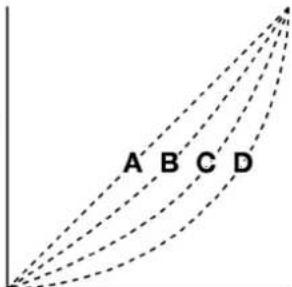
Battery Power & Wall Power Brightness: These settings determine the brightness of the screen during normal operation while on battery power (MPC Live/Live II only) and wall power: Dimmest, Dim, Bright, or Brightest.
Power On Screen (MPC Live, MPC Live II only): This determines if/when a special screen will appear when you power on your MPC Live/Live II. On this screen, you must tap and hold a button for a moment to begin using MPC Live/Live II or it will automatically power off. This feature prevents it from powering on accidentally and wasting battery life. You can set it to the following options:
Never: The screen will never appear.
When On Battery: The screen will appear only if you power on MPC Live/Live II while using battery power.
Always: The screen will always appear.
Tap Tempo: This determines how many times you must press the Tap button before the new tempo is recognized.
Flash Tap Tempo Light: When enabled, the Tap button's light will flash in time with the tempo. When disabled, the Tap button's light will be off.
Bank Button Press: This determines how the Pad Bank buttons work.
Select A-D: Pressing a Pad Bank button once will select the corresponding bank from Pad Banks A–D. Pressing and holding Shift while pressing a Pad Bank button will select the corresponding bank from Pad Banks E–H.
Select/toggle bank: Pressing a Pad Bank button will alternate between the corresponding bank from Pad Bank A–D and Pad Bank E–H. In other words, you do not need to hold Shift to select one of Pad Banks E–H.
Shift + Q-Link Press: This setting determines whether pressing Shift and the Q-Link button opens Q-Link Edit or Cycles Backwards between the Q-Link columns.
Global Pitch Bend: Enable this option to override the pitch bend settings of all tracks, so that those with pitch bend disabled or set to different ranges will only use the Global Range instead. When disabled, all tracks may use their individual pitch bend settings.
Range Down / Range Up: Use these fields to determine the range of pitch bend in semitones.
VU Meter Source (MPC X/X SE only): This determines what audio signal level is shown in the level meters (on the right side of the screen). When set to Main, the level meters show the audio signal sent out of Outputs 1/2 (the Main L/R outputs on the rear panel). When set to Current Track, the level meters show the audio signal of the currently selected track.
Date: This is the current date, formatted as Month / Day / Year. When saving files on MPC in Standalone Mode, the file will include the current date in its metadata. If you use MPC in Controller Mode, this setting will be overwritten with the current date of the host computer.
Time: This is the current time, formatted as Hour : Minute. When saving files on MPC in Standalone Mode, the file will include the current time in its metadata. If you use MPC in Controller Mode, this setting will be overwritten with the current time of the host computer.
Time Zone: This is the current time zone, formatted as Continent / City, which you can change here.
Sequencer
The settings on this screen determine how sequencing works in the Grid View and in the Step Sequencer.
Note Length (Playback): This determines if/how events are cropped if they exceed the length of the current track during playback.
As Recorded: Events will play back exactly as they were recorded, even if they overlap themselves when the sequence loops.
Truncate Length: If the length of an event exceeds the length of the sequence, it will be truncated. This ensures that the event will not overlap itself when the sequence loops.
Track Mute State Per Sequence: When enabled, you can maintain separate track mute statuses when changing sequences. This can allow you to create unique mute setups for each sequence, providing greater flexibility in live performance and arrangement creation.
Solo Behavior: This determines the behavior of the Solo buttons. When set to Single, only one track can be soloed at a time by default. However, you can still press and hold Shift to solo multiple tracks at the same time. When set to Multi, you can solo multiple tracks at the same time by default.
Rec Arm Behavior: This determines the behavior of the Record Arm buttons. When set to Single, selecting a different track will automatically arm that track and disarm all other tracks. This is the default mode and is the same as previous MPC releases. You can also arm multiple tracks on Single mode by holding Shift and tapping each track's record button. When set to Multi, you can tap any track's record button to add it to the group of armed tracks.
Record Track Mute and Solo Events: When enabled, track mute and solo events are recorded when you are in Track Mute Mode (timing correct settings will affect the recorded position events). When disabled, track mute and solo events will not be recorded while in Track Mute Mode. This feature is useful if you want to use Track Mute Mode to record track mutes or solos into your sequences as opposed to using Track Mute Mode for performance or listening purposes only.
Record Pad Aftertouch Events: When enabled, pad aftertouch data (from the MPC hardware's pressure-sensitive pads) will be recorded. When disabled, pad aftertouch data will be ignored.
Place Events Recorded During Count-In at Start Point: When enabled, pressing a pad during the recording's pre-count will record that note event at the start of the recording (this is how the MPC3000 worked). When disabled, no notes will be recorded until the pre-count is finished and recording has begun.
Note: This setting is ignored when recording with the Arpeggiator active.
Note Length (Recording): This determines if/how events are cropped if they exceed the length of the current Sequence during recording:
Truncate To Sequence Length: If the length of an event exceeds the length of the sequence, it will be truncated. This ensures that the event will not overlap itself when the sequence loops.
Truncate To Sequence End: If an event exceeds the length of the sequence, it will be truncated to the end of the current sequence. In other words, the event will stop playing when the sequence ends or loops.
As Played: Events will play back exactly as they were recorded, even if they overlap themselves when the sequence loops.
For example, if you record a note starting on the second bar of a 4-bar loop and hold it for 5 bars, the note will end: at bar 7 (As Played), at bar 6 (To Sequence Length), or bar 4 (To Sequence End). See image for details.

Q-Link Playhead Increment: This determines how the playhead moves when
controlled by the Q-Link knob. Select 1/16 Note to lock playhead movement to 1/16 notes, or select TC Division to have the playhead movement tied to the current Timing Correct division. This value can be set in the Timing Correct window in Grid View by tapping the clock icon at the bottom-left of the grid.
Q-Link Swing Control Applies TC Settings on Release: When enabled, turning the Q-Link knob assigned to Swing and then releasing it will immediately apply that Swing setting. When disabled, you must use the Timing Correct window to apply the Swing setting.
Display Resolution: This is the display resolution (in PPQN—pulses per quarter note) of pulse values in certain areas of the operating system. Please note that this setting affects the display resolution, not the timing.
Project Defaults
The settings on this screen determine various default values for any new project that you create.
Default Tempo: This is the default tempo in BPM.
Default Global Tempo: When enabled, the default tempo value will be used for the global tempo. When disabled, the default tempo will be used for sequences.
Default Mode: This determines the default mode when MPC is powered on; Main Mode or Sounds mode.
Default Q-Link Mode: This determines the default Q-Link Mode: Screen, Project 1–2, Track, Pad Scene, Pad Parameter, Track FX Rack, MIDI, Volume, Pan, Send 1–4.
Default Sequence Bars: This determines the default number of bars of a new sequence.
Default Sequence Loop: This determines whether loop is enabled by default or not.
Default Time Signature Numerator: This determines the default number of beats per bar in the time signature.
Default Time Signature Denominator: This determines the default note value of each beat in the time signature.
Default Pad Slice: This determines how new samples will play when you load them or record them into a project. When set to Pad, the Slice menu in Track Edit Mode will be set to Pad, which lets you set the start point, end point, etc. for the layer. When set to All, the Slice menu in Track Edit Mode will be set to All, in which the entire sample plays.
Default Drum Filter: This determines the default type of filter that drum tracks will use. See Appendix > Glossary > Filter to learn about this.
Default Plugin Synth: This determines the default instrument plugin that a new plugin track will use. Use the window that appears to select it.
Default Audio Monitor: This determines the default audio monitoring behavior: Off (default), In, Auto, or Merge.
Default MIDI Monitor: This determines the default MIDI monitoring behavior: Off, In, Auto (default), or Merge.
Use Fixed Track/Row Color: Check this box to enable all tracks to be created using a fixed color.
Default Track/Row Color: Use this option to select the default color used when the Use Fixed Track/Row Color option is enabled.
Enable Pads User Level By Default: Check this box to enable all pads to play at the set user level by default. Leave this box unchecked to use standard velocity response by default.
Default Pads User Level Velocity: This sets the default pad velocity that is used when the Enable Pads User Level By Default setting is on. You can also set the user level velocity by pressing and holding the Full Level button on your MPC hardware.
Project Load/Save
The settings on this screen determine if (and how) projects are automatically saved. If you are using MPC hardware as a controller, you can also define files to load automatically.
New Project Behavior: This determines what is loaded when a New Project is selected: and Empty Project, the default Factory Project, or the User Auto Load Project file.
User Auto Load File: Use this field to select a project (.xpj) or program (.xpm) to load automatically anytime you open the MPC software or your standalone MPC hardware.
Note: If the New Project Dialog setting under Project Defaults is set to Demo or Demo/Template/Recent, selecting Empty Project will load the Auto Load project if one is selected. If no Auto Load project is selected, choosing Empty project will load an empty project. If you have an Auto Load project selected and would still like to create an empty project, press and hold Shift and then tap Empty project. If the Project Defaults is set to Off, the Auto Load project will be loaded on startup.
New Project Dialog: This determines what options you see when you start a new project. When set to Off, a new project will be empty with no preconfigured settings except for the project defaults shown here. When set to Demo, you can choose to load a demo project (from several different genres) as a starting point or an empty project. When set to Recent, you can select from recently loaded projects. When set to Demo/Template/Recent, you can choose to load a demo project, a project template file, or a recently loaded project. You must have a project in the Template File field of the Project Load/Save tab to select a template in this window.
Template File: Use this field to select a project template that will load automatically when you select User Template in the New Project Dialog window. (If you select the Save as Template box when saving a file, it will be shown in this field.) For the User Template option to be available, New Project Dialog (in the Project Defaults tab) must be set to Demo or Demo/Template/Recent.
Temporary File Location: Use this field to select a location on your device or connected external media as a record path for temporary files.
Auto Save Enabled: When enabled, your project will automatically save after each Timeout interval. When disabled, your project will not be automatically saved; you may save only manually.
Auto Save Timeout: Use this field to select how often your project will automatically save.
General
The settings on this screen determine how other features work in the hardware and operating system.
Vintage Mode: This determines the type of emulation applied to the audio output. You can apply the particular sonic qualities of, for example, the MPC3000 or MPC60, or of course no emulation (None).
Audition Auto Play: This determines how long a sample will sound when auto-previewing it.
Audition Outputs: This determines which pair of outputs will play any auditioned sounds (Out 1,2–7,8 in Standalone Mode, Out 1,2–31,32 in Controller Mode; as available). These sounds include: samples, tracks, and projects in the Browser; sample playback, Cue Preview, and Slice Preview in Sample Edit Mode; and sample playback in the Keep or Discard Sample window in the Sampler.
Cue Preview: This determines if/how audio is played as you move the cue playhead. As you move the cue playhead through a sample waveform, you can set it to play the small part of the sample before the cue playhead (Before), play the small part of the sample after the cue playhead (After), or not play at all (Off). You can also set this in Sample Edit Mode (see Modes > Sample Edit Mode > Settings).
Slice Preview: This determines if/how audio is played as you move a slice marker. As you move the slice marker through a sample waveform, you can set it to play the small part of the sample before the slice marker (Before), play the small part of the sample after the slice marker (After), or not play at all (Off). You can also set this in Sample Edit Mode (see Modes > Sample Edit Mode > Settings).
Show Mode Shortcut Panel: When enabled, you can access the mode shortcut panel by swiping to the right on the grey bar on the left-edge of the screen. You can use the Mode Menu layout editing to put your five most-used modes in this shortcut panel for easy access. This is disabled by default.
BPM Detection Range: This defines the range of detectable BPM values when you use any automatic BPM detection function in the software or when you press the Tap button to enter a new tempo.
Show Q-Link Status When Touched: When enabled, touching the Q-Link knobs opens a pop-up showing the current Q-Link assignments and values.
Automation Lane Follows Q-Links: When enabled, touching a Q-Link will automatically show the current automation status in the Grid View automation lane.
Collect Usage Statistics: This determines whether or not your usage statistics will be sent occasionally to us, enabling us to improve the MPC experience.
Splice
The settings on this screen control integration with the Splice platform.
To access Splice from this page:
- First, make sure your MPC hardware is connected to a Wi-Fi network. See Preferences > Wi-Fi to learn how to connect to a wireless network. You will also need access to a web browser.
- Tap the Get Login Code button. (If you are not connected to a network, you will be prompted to do so before the Get Login Code button appears.)
- Follow the on-screen instructions to link your MPC to your Splice account via a web browser. It may take your MPC a few moments to successfully link.
- A message will appear on screen when the link has been successfully established. Tap OK to continue and return to the Splice Preferences page.
- Once the process is complete and your MPC has been paired to your Splice account, tap the Sync Files button to download samples from your Splice account via Wi-Fi to a drive of your choice.
By default, files will be stored on the Internal drive. You can change the selected drive by tapping the Change button under Sync Files To Drive.
To browse samples imported from Splice:
- Open the Browser.
- Under the Content tab, tap the Splice shortcut icon to view samples downloaded from your Splice account.
If nothing appears, make sure that you have connected your Splice account and synced your files by following the directions above. - The right-side of the browser will display your Splice samples organized into a series of top-level folders, allowing you to easily browse your sample library by BPM, Instrument, Key, Pack or Tag. The All Your Samples folder will show a list of all samples you have downloaded.
Note: The original sample files are stored in the By Pack folder on your drive. Other folders such as By Instrument contain internal links to help sort the samples by various tags. If the By Pack folder on your drive is deleted, the files in the remaining folders will become unusable. To fully remove all files, the entire Splice directory should be deleted.
IMPORTANT: Drives formatted using the FAT32 system do not support these internal links. For these drives, and on the internal storage drives of some earlier MPCs, samples will only be sorted in the By Pack folder. We recommend using an exFAT file system on external drives used with MPC, as it is the most robust one supported by both Windows and macOS.
To view the number of samples available to download from your account, tap the Check For Update button.
To log out of a Splice account, tap the Log Out button.
Save Window
The Save Window lets you save your project, tracks, and samples in a variety of ways.
To open the Save window, press Menu to open the Menu and then tap Save at the top of the screen.
On MPC Key 37, you can also press the Save button.
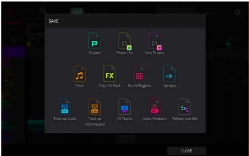
To save a project, tap Project or Project As. If a project has not been saved before, both options will open the Save window, described below. If a project has been saved before, tapping Project will automatically overwrite the most recently saved version.
Tap New Project to open a new project.
Tap Track to save the current track.
Tap Track FX Rack to save the current track inserts.
Tap Drum Program when a Drum track is selected to save the current drum kit.
Tap Plugin Program when a Program track is selected to save the current plugin program.
Tap Keygroup when a Keygroup track is selected to save the current keygroup.
Tap MIDI Program when a MIDI track is selected to save the current MIDI program.
Tap CV Program when a MIDI track is selected to save the current CV program.
Tap Sample when an audio sample is selected to save it.
Tap Track as Audio to save the currently selected track as audio.
Check the Include Track Volume/Pan Settings box to include these settings in the export.
Check the Bypass Track Effects Plugins box to not include track effects plugins in the export.
Use the Audio Tail field to set the amount, in seconds, of extra time added to the end of the resulting audio files.
Use the Bit Depth field to set the bit depth to 8, 16 or 24.
Use the Sample Rate field to set the sample rate to 44.1, 48, 88.2 or 96 kHz. In most cases, we recommend selecting 44.1 kHz.
Tap Track as MIDI/Pattern when a MIDI track is selected to save it as a MIDI pattern file.
Use the Export MIDI As field to set the export the track as MIDI files or MPC Pattern files.
Tap All Tracks to save all current tracks in the project.
Use the same settings for Track as Audio or Track as MIDI/Pattern depending on how you would like to save the tracks.
Tap Audio Mixdown to save the project as an audio mixdown.
Use the Start Bar and End Bar fields under Audio Length to set the time range that you want to mix down. You can add a number of seconds to the end of the mixdown to capture any ringing notes or effects (such as a reverb tail) by adjusting the Audio Tail field.
Use the fields under Render Source and Render Options to set the parameters for the audio mixdown. Check the Separate Tracks box to render each track of the arrangement as stems.
Use the fields at the bottom of the screen to configure the audio mixdown settings. You can set the File Format, Bit Depth, and Sample Rate.
Tap Ableton Live Set to save the project as an Ableton Live set.
Use the Export MIDI As settings to choose how MIDI tracks are exported, either as Audio files or MIDI files. When using Plugin, Drum or Keygroup tracks, you can render sequences as Audio to preserve the sound of the instruments, or render sequences as MIDI data.
Check the Include Track Volume/Pan Settings box to include these settings in the export. When disabled, the volume and pan settings will be set to 0 dB and center (C), respectively.
Check the Bypass Track Effects Plugins box to deactivate any third-party effect plugins used with the track for the export. When disabled, those effects will be activated.
Use the Audio Tail field to set the amount, in seconds, of extra time added to the end of the resulting audio files.
Use the Bit Depth field to set the bit depth to 8, 16 or 24.
Use the Sample Rate field to set the sample rate to 44.1, 48, 88.2 or 96 kHz.
Tap Drum Pads as Stems when a drum track is selected to render an audio stem for each pad with events in the drum track. This allows you to export your stems to a DAW for greater flexibility in mixing and post-production.
Use the Audio Tail field to set the amount, in seconds, of extra time added to the end of the resulting audio stem files.
Use the fields at the bottom of the screen to configure the audio mixdown settings. You can set the File Format, Bit Depth, and Sample Rate.
After selecting the save type, use the following to select a save location:
Tap a device from the Storage column on the left side to select it.
Internal is the internal drive of your MPC hardware.
MPC Documents is a shortcut to the MPC Documents folder on the internal drive of your MPC hardware.
If you have storage devices connected to USB ports or SD card slot of your MPC hardware, they will appear in this column, as well.
Double-tap a folder to enter it. You can also tap one of the five folder buttons in the upper-right to jump immediately to pre-assigned file paths set in the Browser.

Tap New Folder to create a new folder. Use the virtual keyboard that appears to enter a name, and then tap Do It. You will immediately enter the new folder.
Tap the folder/ icon in the upper-left corner to move up one folder level.
Tap the File Name field at the bottom of the screen to name the file.
Tap Save to save the file.
Check the Save as Template checkbox before tapping Save to save the file as a project template file. This file will be shown in the Template File field in the Preferences' Project Load/Save tab.
Tap Cancel to cancel and return to the Menu. Alternatively, tap the ← icon in the upper-left corner.
Pull-Down Menu
The pull-down can be accessed from any MPC3 mode, giving you quick and easy access to a variety of commonly used tools and information.
To open the pull-down menu, tap and drag from the middle-top of the screen.
Use the > and < buttons to cycle between the two pull-down menu pages.
To close the menu, simply swipe it back upwards to the top of the screen.
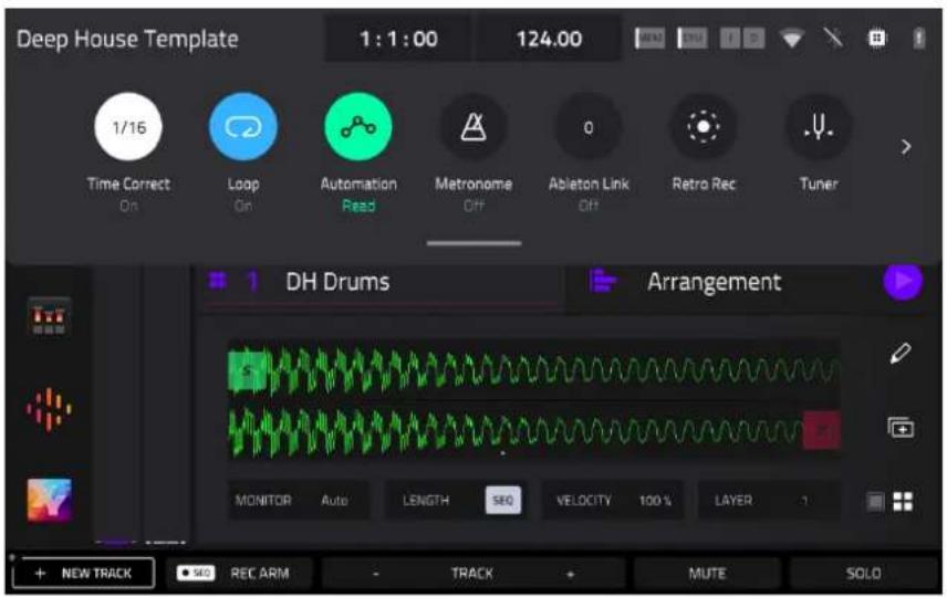
The pull-down menu contains the following controls on the first page:
The Project Name is shown at the top-left corner of the menu.
The time counter shows the current playhead position. Tap here to open the Locate window, which allows you to adjust the playhead position and quickly jump to specific points in your project.
The BPM field displays the tempo of the sequence. Tap here to open the Tempo window to adjust the BPM.
The Mem indicator shows your MPC hardware's current RAM usage, and the CPU indicator shows your MPC hardware's current CPU usage. Tap here to open the System Resources window.
The In and Out boxes indicate your MPC hardware is receiving or sending (respectively) MIDI messages from or to your computer. Tap here to open the MIDI Monitor and view the latest incoming or outgoing MIDI messages.
The Wi-Fi and Bluetooth icons display the current network and Bluetooth connection status. Tap each icon to open their respective setup pages in the Preferences.
The chip icon/computer icon shows whether you are in Standalone or Controller Modes. Tap here to switch modes.
The TC icon enables or disables global timing correct. Tap and hold this icon to open the Timing Correct (TC) window, which contains various settings to help quantize the note events in your sequence.
The Loop button enables or disables sequence looping.
The Automation button indicates the global Automation state. Tap to cycle between Read and Write. Press and hold Shift and tap here to turn global automation Off.
The Metronome button enables or disables the metronome. Tap and hold this icon to open the Metronome (Click/Metro) settings window.
The Ableton Link button displays the current Ableton Link status. Tap to turn Ableton Link on or off.
The Retro Rec button enables retrospective recording. Your MPC hardware will capture MIDI events in the background, so you can recall a performance when record was not enabled. Select your desired track, and then tap this button to capture the recently played notes.
The Tuner button opens the built-in Tuner, which allows you to easily tune any connected audio source.
On the second page of the pull-down menu are controls for creating macro controls. This allows you to set up controls for parameters that might not be shown in a particular mode, or set up controls with multiple parameters across different modes for expressive performances.
See Operation > Modes > Q-Link Edit for more information on creating macro assignments.
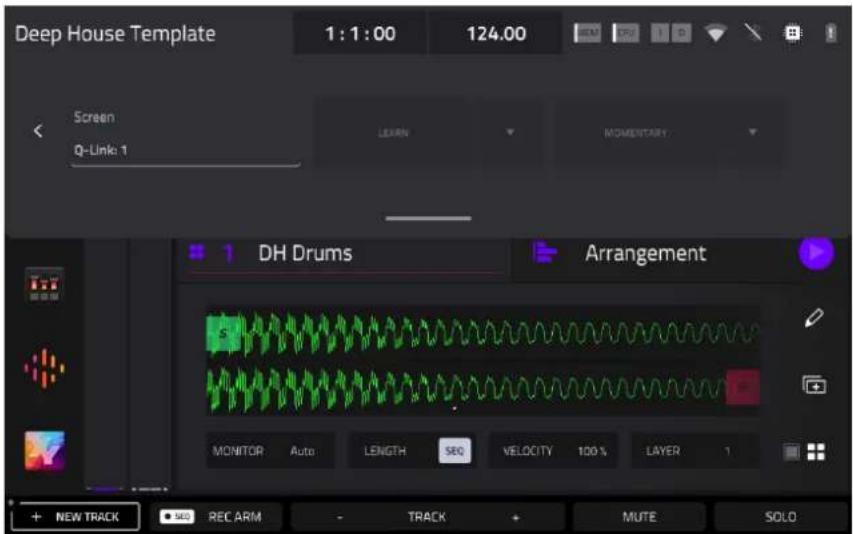
Tap the Current Control field to select the type of control you want to create an assignment for.
Tap the Learn button to activate MIDI learning. Once activated, the Q-Link Bank LED on your MPC hardware will blink. Navigate to the mode that displays the parameter you would like to learn, and then adjust that parameter. The screen will show a message, "Learned [parameter] to [macro control]." To lock in the assignment, tap the Learn button again.
To learn multiple parameters to a macro, simply navigate to more parameters while Learn is engaged (see Modes > Q-Link Edit > Learning Macro Assignments for more information on learning macros).
To learn another parameter to a macro that replaces the previous parameter, tap the down arrow next to the yellow Learn button, and then uncheck the Add box. Repeat the steps above to replace the previously learned parameter with a new one.
To learn a new parameter while also setting it to a range of values, tap the down arrow next to the yellow Learn button, and then check the Range box. While Learn is engaged, adjust the parameter to the low and high points of the value range that you want to control. When the assignment is locked in, the macro will control the parameter in the set value range.
To use a single macro to, for example, mute/unmute multiple tracks at the same time, tap the down arrow next to the yellow Learn button, and then check the Toggle box. Repeat the steps above to learn a parameter, which will toggle on/off when the control is touched or moved.
To use a macro to send the max value of a parameter, tap the down arrow next to the yellow Learn button, and then check the Trigger box. Repeat the steps above to learn a parameter, which will send its maximum value when the control is touched or moved.
Tap the Momentary button to turn momentary behavior on or off.
When on, moving the knob will adjust its parameter, but the parameter will immediately return to its original position (when you turned Momentary on) when you release the knob.
When off, moving the knob will adjust its parameter, and the parameter will remain at its new setting when you release the knob.
Tap the arrow next to the Momentary to adjust additional settings for when the macro control is released:
To revert the macro parameter(s) to its minimum value on release, check the Go to Minimum box.
To revert to the last value state before the macro was changed on release, check to Go to Previous box.
Time Counter / Locate
Many MPC modes feature a time counter in the toolbar. This displays the current playhead position in Bars:Beats:Ticks. Double-tapping the time counter opens the Locate window, where you can adjust the playhead position, manage loop and record settings, and quickly jump to specific points in your project.

![LOCATE TIME LOCATORS Locator 1 1: 1: 0 ✓ × Locator 2 9: 1: 0 ✓ × Locator 3 13: 1: 0 ✓ × Locator 4 21: 1: 0 ✓ × Locator 5 25: 1: 0 ✓ × SET [=] CLOSE](/content/2026/05/883354/images/4292b03a7c30fbd545c32adf1932b761f5b695d62d2c0a6d436505b77447f4de.jpg)
The Locate popup is divided into two sections:
The Time tab is used to adjust the position of the playhead in the arrangement, as well as adjust Loop and Record settings.
Use the Bars:Beats:Ticks fields to move the playhead in the arrangement. You can also tap the Step and Bars arrow buttons to move the playhead by the specified amount.
Tap the Loop button to enable loop in the arrangement. Use the Loop Start and Loop End fields to set the length of the loop. Alternatively, you can set the loop length according to the Locator markers in the timeline. When Set Loop Range By Locator is set to On, the loop range will automatically adjust to the length between the selected Locator and the next Locator. The current loop region is always displayed in the timeline of the arrangement whether it is activated or not.
Use the Auto Record field to enable automatic recording when the loop starts. When enabled, recording will begin immediately when the arrangement loops.
The Locators tab is used to edit the six Locator markers which can be applied to the timeline.
Tap Set to add a locator.
To rename a locator, tap the keyboard icon, and then use the keyboard to enter a new name.
Use the Bars:Beats:Ticks fields to adjust the position of the locator.
To edit the color of the locator, tap the eyedropper icon, and then select a color from the list.
Tap the X icon to delete the locator.
To close the Locate window, tap Close, the X in the upper-right corner, or anywhere outside the window to return to the arrangement.
Timing Correct (TC)
The Timing Correct window contains various settings to help quantize the events in your project. You can quantize note events on MIDI tracks or track regions on audio tracks (though you cannot apply all types of quantization to audio tracks).
To open the Timing Correct settings:
In Main Mode or List Edit Mode: Tap the TC field at the top of the screen.
In Arrange Mode, the Step Sequencer, or Track Mute Mode: Tap TC at the bottom of the screen.
In Grid View: Tap the clock icon in the bottom-left corner of the screen.
In Track View: Press and hold Shift and tap TC at the bottom of the screen.
Press the TC / On/Off button (MPC Live II/One/Key 61/Key 37 only).
To enable or disable global timing correct, tap the Global Timing Correct button so it is on. Alternatively, press and hold Shift and press the track 6 Track Assign button.
Tap Do It to apply the settings you selected, or tap Close to cancel and return to the previous screen.


Use the Type selector to set how timing corrections are applied.
- Start: The entire note event or audio track region will be nudged forward or backward so the start point aligns with the closest time division marker in the grid. You can apply this to MIDI tracks or audio tracks.
- End: The end points of note events will be extended or shortened to align with the closest time division marker in the grid. The start points will remain untouched. You can apply this to MIDI tracks only.
- Length: The end points of note events will be extended or shortened so that each event's length is a multiple of the time division, regardless of where it is in the grid. The start points will remain untouched. You can apply this to MIDI tracks only.
- Legato: The end points of note events will be extended or shortened to create a long, unbroken phrase from the first note event's start point to the last note event's end point. Each note event will sustain until another note event starts. If multiple note events start at the same time (and are not the last note events), their lengths will become identical. Selecting Legato disables all other options in this window. You can apply this to MIDI tracks only.
natural_image
Grid of colored rectangular blocks on black background, no text or symbols present
natural_image
Abstract pattern of orange and red horizontal bars on a black grid background (no text or symbols)Without legato applied. With legato applied.
Use the Time Division selector to set the quantization value. Events will “snap” to these time divisions on the grid. The T indicates a triplet-based value.
Use the Swing field to set the amount of swing from 50% to 75%. Swing lets you “shuffle” your beats—from subtle to extreme.
Use the Shift Timing field to shift all events by clock ticks.
Use the Window field to set how many events around a quantize value will be quantized. Any events outside this range will not be quantized; events inside will.
Use the Strength field to set how strictly events will be quantized (i.e., shifted toward the quantize value). Lower values move events a little bit towards the closest quantize value, resulting in a less mechanical feel than a strict quantization (a higher value).
Use the Events selector to set the target range for the time correction. You can apply the time correction to All note events or to just the Selected ones.
To select note events to which to apply time correction, either use the various tools in Event View or Region View or press the pad with the desired events (while Hitting Pad Selects All Events is set to On). You must do this before opening the Timing Correct window.
When Range is selected, you can define the locations (From and To) as well as the pads or keys that will be quantized.
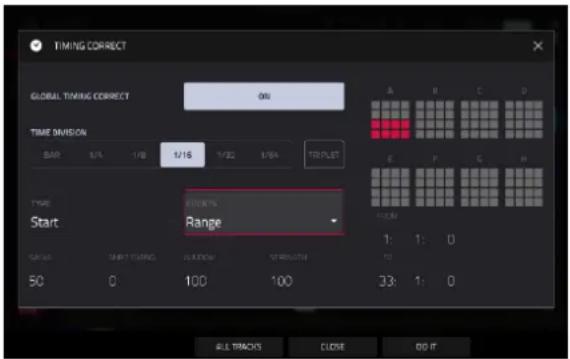
Metronome (Click/Metro)
The Click/Metro window contains all settings regarding the metronome (click track).
To enable or disable the metronome, press and hold Shift and press the Play Start button. You can also tap the Metronome icon in the Pull-Down Menu.
To open the metronome settings, tap the Metro icon at the top of the screen in Main Mode. You can also tap and hold the Metronome icon in the Pull-Down Menu.

Use the Count-In field to set if/when the metronome counts before recording.
• Off disables the metronome pre-count.
• Record enables the pre-count during recording only.
• Record + Play enables pre-count in both Record and Playback Modes.
Use the Enable field to set if/when the metronome is enabled.
• Off disables the metronome.
• Play enables the metronome sound during playback only.
• Record enables the metronome sound during recording only.
• Record + Play enables the metronome to happen in both Record and Playback Modes.
Use the Rate field to select the metronome click's time division: Auto, 1/4, 1/4T, 1/8, 1/8T, 1/16, 1/16T, 1/32 or 1/32T. T indicates a triplet-based time division. When set to Auto, the Metronome will automatically adjust to the current time signature's denominator value.
Use the Sound field to select the sound that you want to hear for the metronome: Sidestick 1, Sidestick 2, Clap, Metroclick, Shake, Tambourine, or MPC Click.
Use the Volume knob to set the volume of your metronome click.
Tap the On/Off button to enable or disable the metronome.
Use the Output field to set which pair of outputs will play the metronome click: Out 1,2, Out 3,4 or an individual Out 1–4.
Automation
You can set the global automation setting, or individual tracks' automation settings, to be "written," "read," or disabled entirely by using the automation buttons described below.
Global
Global automation buttons change the automation state for all tracks in the project. These buttons can be found in the toolbar of modes like Main Mode and Arrange Mode, and in the project Pull-Down Menu.
When you tap this button to change its state, it will change the automation state for all tracks in the project.
Tap the global automation button to cycle through its two states. Alternatively, press Read/Write (MPC X, MPC Key 61) or Automation (MPC Key 37).
When set to Read (R), automation data will be read but not recorded. (Think of this as a protective feature to prevent accidental changes to your automation while recording.)
When set to Write (W), automation can be recorded and will overwrite any existing automation. (Make sure not to touch the XY pad accidentally while you are recording.)
Press and hold Shift and tap the global automation button to disable global automation. When off, automation data will be ignored. Tap the global automation button again to enable global automation. Alternatively, press and hold Shift and press Read/Write (MPC X, MPC Key 61) or Automation (MPC Key 37).
Important: If you have already recorded automation and turn it off, the track will still use the effect and its parameter values at the point where you turned it off.
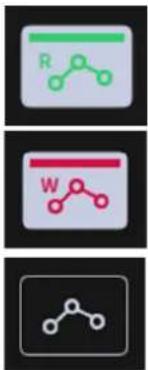
flowchart
graph TD
    A["R"] --> B["Node"]
    B --> C["Node"]
    C --> D["Node"]
    D --> E["Node"]
    E --> F["Node"]
    F --> G["Node"]
    G --> H["Node"]
    H --> I["Node"]
Tracks
In addition to global automation, you can set automation for individual tracks by using the track automation buttons. These are found in channel strips, such as those in Main Mode or in Channel Mixer Mode.
Note: Remember that tapping the global automation button will change the automation state for all tracks in the project; if they were originally different, all of them will then match the global automation state.
Tap the track automation button to cycle through its two states.
When set to Read (R), the track will read automation data but will not record any additional automation over it. (Think of this as a protective feature to prevent accidental changes to your automation while recording.)
When set to Write (W), the track can record automation. (If you have any Q-Link knobs assigned to automatable parameters, make sure not to touch any accidentally while you are recording.)
Press and hold Shift and tap the track automation button to disable track automation. When off, the track will ignore automation data. If you have already recorded or entered automation, tapping this will switch between Read (R) and Write (W) only, but you can override this and turn it off by pressing and holding Shift while pressing or tapping the button.
Important: If you have already recorded automation and turn it off, the track will still use the effect and its parameter values at the point where you turned it off.
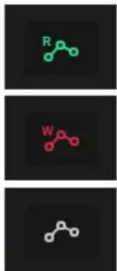
flowchart
graph TD
    A["R"] --> B["W"]
    B --> C["..."]
To record automation to a track:
- Make sure the Global or Track automation state is set to Write (W).
- Press the Play button to start recording. Record automation using the Q-Links, XY Pad, or by adjusting the onscreen controls.
Note: If you are recording MIDI CC automation, make sure the ● SEQ REC ARM button at the bottom of Main Mode is enabled, and then press the OVERDUB button on your MPC hardware to arm recording before playing. - When you are finished, press Stop to stop recording. Make sure to set the automation state back to Read (R) to listen back to your recorded automation.
You can also manually add and edit automation in Grid View, List Edit Mode, and the Step Sequencer. See these sections to learn more about how automation functions in each mode.
To quickly clear automation from a track:
- Tap the Sequence Edit pencil icon in Main Mode, and then select Erase from the Sequence Edit window. Alternatively, press the Erase button on your MPC hardware.
- Select Automation as the Erase type.
- Select the desired automation parameter(s) that you want to erase, and set the desired time frame.
- Tap Do It to clear the automation from the track in the current sequence.
Alternatively, you can delete individual automation events using Grid View, List Edit Mode, and the Step Sequencer.
16 Level
Press the 16 Level button on your MPC hardware to activate or deactivate 16 Level.
When first activated, the selected pad (Pad A01 by default) will be temporarily copied to all 16 pads. The pads will now output the same note number as the initial pad, but a selectable parameter will be fixed at values that increase as the pad numbers increase (e.g., Pad 1 is the minimum, Pad 16 is the maximum), regardless of how hard you press them.

In the 16 Levels screen that appears, use the Type selector to choose the parameter: Velocity, Tune, Filter, Layer, Slice, Articulation, Attack, Decay, Probability, or Ratchet.
To select a pad, do any of the following (while the 16 Levels window is open):
- Press and hold 16 Level, and then press the desired pad.
- Tap the 16 Levels checkbox to uncheck it (temporarily disabling the feature), press the desired pad, and then tap the 16 Levels checkbox again to check it.
- Tap the Pad field, and use the data dial or - / + buttons.
• Double-tap the Pad field, and tap the desired pad in the list that appears.
If Type is set to Tune, use the Original Pad field to select which you pad you want to use the original pitch of the sample/samples. Alternatively, hold Shift and press the desired pad.
If Type is set to Layer, pads with multiple samples will play back each layer according to the Velocity Start and Velocity End settings for each layer.
If Type is set to Slice, pads with multiple slices will play back each slice in order, starting with Pad 1.
If Type is set to Articulation, Pad 1 will play the original sample unchanged, and Pads 2–16 will play the first 15 articulations in the Articulation list. See Track Edit Mode > Drum Tracks > Effects to learn more about articulations.
If Type is set to Probability, the 16 pads will represent the probability that the note will play, from lowest to highest.
If Type is set to Ratchet, the 16 pads will represent increasing ratchet subdivision values.
Pad Perform
The Pad Perform window lets you assign musical scales/modes, chords, or progressions to the pads for more creative performance.
To open the Pad Perform window, do any of the following while using a keygroup track, MIDI track, plugin track, or CV track:
- Tap Pad Perform icon in the Track section of Main Mode.
- Press Pad Perform (MPC X).
- Hold Shift and press 16 Level (MPC Live, MPC Live II, MPC One, MPC Key 61, and MPC Key 37).
Although you can enter Pad Perform Mode while using a drum track, it does not work.

The touchscreen will show the current pad bank's mapping of notes or chords.
Use the type selector in the top-left to determine what will be mapped over the pads:
Chromatic: Each pad is assigned a note, ascending by one semitone with each pad. Pads with notes in the key determined by the Scale will be lit, while pads with notes between the scale degrees will be unlit.
Notes: Each pad is assigned a note, ascending by one scale degree with each pad.
Chords: Each pad is assigned a chord, the root note ascending by one scale degree with each pad. All available chords will play in the key determined by the Scale.
Chromatic Chords: Each pad is assigned a chord, the root note ascending by one scale degree with each pad. You can play any chord type regardless of the key determined by the Scale. Essentially, this is like the Chords setting but with more options to play chords out of the set key.
Progressions: Each pad is assigned a chord in a chord progression. You can play the pads in (or out of) order to construct songs quickly. The available chords are determined by the Chord field. User progressions can be created in the MPC software and transferred to your MPC hardware by creating a folder named Progressions on the root level an external storage device and copying your progression files (.progression) there. By default, progressions are saved here:
Windows: C:\Program Files\Akai Pro\MPC\Progressions and/or C:\ProgramData\Akai\MPC\Progressions macOS: \~/Library/Application Support/Akai/MPC/Progressions
Your MPC hardware will scan the Progressions folder you created and add them to the list of available progressions.
Custom: Each pad is assigned a custom note. Tap the Edit Note Map button to begin editing. Tap a pad or use the Pad field to select a pad, and then use the MIDI Note field to set the desired note. When you are finished editing, tap Close, the X, or anywhere outside the window. You can also choose from three Custom presets: Chromatic C1, Chromatic C2, or Classic MPC.
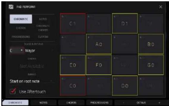

Chromatic Notes in Pad Perform Mode. Notes in Pad Perform Mode.
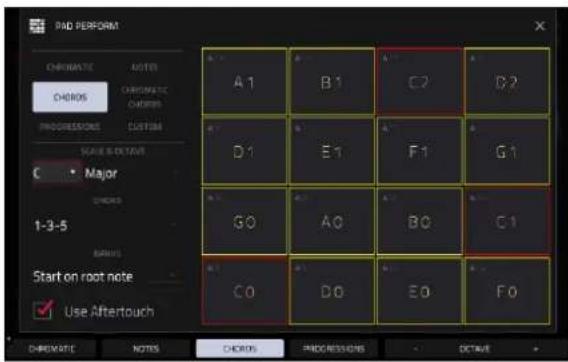

Chords in Pad Perform Mode. Chromatic Chords in Pad Perform Mode.

Progressions in Pad Perform Mode. Custom Map in Pad Perform Mode
Use the Scale & Octave fields to determine the root note and the scale type.
Root Note (pitch and register): This is the starting point of the scale. The available notes are all chromatic notes across the range of the pads. The pad that's assigned the root note will be lit differently (and highlighted on the screen) to indicate where the scale starts in each octave.
Scale Type: This is the scale or mode based on the root note (this is disabled when Type is set to Progressions). The available scales are:
Major Blues (minor) Major Bebop Lydian
Natural Minor Flamenco Whole Tone Mixolydian
Harmonic Minor Gypsy Chromatic Aeolian
Pentatonic Major Hungarian Gypsy Dorian Locrian
Pentatonic Minor Persian
Phrygian
Use the Chord fields to determine what chord type will play when pressing a pad. The chord will use those scale degrees based off the pad's root note. You can use this only when the Type is set to Chords or Chromatic Chords.
When set to Chords, the available chords are:
1-3-5 (major/minor) 1-3-5-7 (major7/minor7)
1-4-5 (sus4) 1-3-5-7b (dominant)
1-2-5 (sus2)
When set to Chromatic Chords, the available chords are:
| Major | Major7 | Augmented |
| Minor | Minor7 | Diminished |
| Sus2 | Major9 | |
| Sus4 | Minor9 |
Use the Banks field to determine how the notes are mapped across the pad banks.
Continuous: Pad 01 of one bank is always one scale degree higher than Pad 16 of the previous bank.
Start on Root: Pad 01 will always be the root note of the scale in every pad bank.
You can use the buttons at the bottom of the screen to quickly select different Types and Chords:
Tap Notes to automatically set the Type to Notes.
Tap Chords to automatically set the Type to Chords.
Tap Progressions to automatically set the Type to Progressions.
Tap Octave -/+ to shift the pad assignments down or up by an octave.
Press Shift+1-3-5 to automatically set the Type to Chords and set the Chord to 1-3-5 (major/minor).
Press Shift+1-4-5 to automatically set the Type to Chords and set the Chord to 1-4-5 (sus4).
Press Shift+1-3-5-7 to automatically set the Type to Chords and set the Chord to 1-3-5-7 (major7/minor7).
Press Shift+1-3-5-7b to automatically set the Type to Chords and set the Chord to 1-3-5-7b (dominant).
Press Shift+Note -/+ to shift the pad assignments down or up by a semitone, essentially raising or lowering the Root Note field by a half-step.
Arpeggiator
Your MPC hardware includes a full-featured arpeggiator and phrase player for melodic track types, as well as traditional note repeat functionality.
To open the Arpeggiator settings:
- Set the current track type to Plugin, Keygroup, MIDI, or CV.
- Open the Arpeggiator window by doing either of the following:
- Press and hold the Note Repeat button, then tap Arp at the bottom-right of the screen.
• Alternatively, press the Arpeggiator F-Key (MPC X).

Tap Enable so it is checked to activate the Arpeggiator. Tap again to Disable the Arpeggiator. Tap Latch so it is checked to latch the Arpeggiator. Tap again to Disable Latch.
The Setup section of the Arpeggiator window sets what kind of arpeggiator will be used and its functions:
Use the Action field to set the type: Arp, Note Repeat, Rhythm, and Pattern. See below for more details about these types and their additional parameters.
Use the Time Division selector to set the note value of each arpeggiator step from 1/1–1/64 beats, including T (triplet) variations. This parameter is not available when Action is set to Pattern.
Note: This setting is tied to the project's Time Division setting, and will not function if Time Division has been set to Off.
Use the Note Length slider to set the length of the played note in each step, from 1–100%.
Use the Velocity field to set the velocity of the arpeggiator notes. Choose As played, From first note, Accented, Full, 3/4, Half or 1/4.
Use the Swing field to set the amount of swing in the arpeggiator from 50% to 75%. Swing lets you "shuffle" your beats—from subtle to extreme.

The Arp mode section of the Arpeggiator window is available when the Action is set to Arp. When this action is selected, hold down a chord and the arpeggiator will play a pattern based on the notes held.
Use the Arp Pattern field to set how the arpeggiator triggers the held notes.
Use the Octaves field to set how many octaves of the held notes the arpeggiator will cycle through.
Use the Variation field to apply rhythmic variation to the set pattern.

The Rhythm section of the Arpeggiator window is available when Action is set to Rhythm. When this arpeggiator action is selected, hold down a chord and the arpeggiator will play the held notes in a rhythmic pattern.
Use the Rhythm Pattern field to choose the pattern played when notes are held.

The Pattern section of the Arpeggiator window is available when the Action is set to Pattern. When this arpeggiator action is selected, hold down a single note to trigger a melodic phrase. As you change what note is held, the melodic phrase will be transposed.
Use the Pattern field to choose the pattern.

The Settings section of the Arpeggiator window offers additional options to control the arpeggiator.
If you have a sustain pedal connected, you can enable Sustain Pedal Latches to use it to control latching.
Use the Latch Mode setting to set the action of the sustain pedal, either Reset or Add.

The Probability section of the Arpeggiator window lets you add further variation to your arpeggiator by adjusting the probability of how notes are played.
Use the Accent (%) field to set the percent probability that a note in the arpeggio is accented.
Use the Normal (%) field to set the percent probability that a note in the arpeggio is normally articulated.

bar
| Category | Probability (%) | | :--- | :--- | | ACCOUNT (10) | 100 | | NORMAL (52) | 100 |The Arpeggiator modifiers section of the Arpeggiator window enables additional controls to modify the arpeggiator.
Tap the Channel Pressure box so it is checked to enable Channel Pressure messages from external MIDI controllers to modify the arpeggiator.
Tap the Expression box so it is checked to enable Expression messages (MIDI CC #11) from external MIDI controllers to modify the arpeggiator.
Tap the Aftertouch box so it is checked to enable Aftertouch messages from the pads or external MIDI controllers to modify the arpeggiator.
Tap the Mod Wheel box so it is checked to enable Modulation messages (MIDI CC #1) from external MIDI controllers to modify the arpeggiator.

Use the Arpeggiator modifier settings field to select what arpeggiator settings are modified by the selected controls, and by how much.
Tap the Modify Time Division box so it is checked to enable modification of the arpeggiator time division. Use the Max Amount to set by how much the time division can be changed, from 1–4. For example, if the Time Division is set to 1/8 and the Max Amount is set to 2, adjusting the selected modifier control will increase the Time Division to 1/8T and 1/16, which are the next two higher time divisions.
Tap the Modify Octaves box so it is checked to enable modification of the arpeggio octave range. Use the Extra Octaves field to select how many additional octaves (on top of what the current Octaves setting is) can be added with the modifier control, from 1–4. For example, if the current Octaves setting is 1 and the Extra Octaves is set to 2, adjusting the selected modifier control will increase the total octaves up to 3.
Tap the Modify Note Length box so it is checked to enable modification of the arpeggio note length. Use the Max Amount (%) field to select by how much percentage the note length is increased, from 1–100%. For example, if the current Note Length setting is 50% and the Max Amount (%) is set to 20%, adjusting the selected modifier control will increase the note length up to 60%.
Tap the Modify Swing box so it is checked to enable modification of the arpeggio swing amount. Use the Max Amount (%) field to select by how much percentage the swing amount is increased, from 1–50%. For example, if the current Note Length setting is 50% and the Max Amount (%) is set to 20%, adjusting the selected modifier control will increase the swing amount up to 60%.
Tap the Modify Variation box so it is checked to enable modification of the arpeggio Variation setting. Use the Max Amount field to select by how the variation setting can be changed, from 1–4. For example, if the current Variation setting is Variation 1 and the Max Amount is set to 2, adjusting the selected modifier control will increase the Variation setting up to Variation 3.
Tap the Modify Probability box so it is checked to enable modification of the arpeggio probability amount. Use the Max Amount (%) field to select by how much percentage the probability amount is increased, from 1–100%. For example, if the current Probability setting is 50% and the Max Amount (%) is set to 20%, adjusting the selected modifier control will increase the probability amount up to 60%.

Erase
The Erase function erases all or part of a track in a specific sequence.
To open the Erase window, press the Erase button. Alternatively, while in Main Mode, tap the pencil icon on the right edge of the Sequence Section, and then tap Erase in the screen that appears.


Use the Sequence field to select the sequence you want to erase.
Use the Track field to select the track you want to erase within the sequence.
Use the Bar, Beat, and Tick fields to set the time range of the sequence you want to erase. The left fields set the start of the time range, and the right fields set the end of the time range.
To select what types of events you erase, select one of the Erase options:
All erases all pad events from the designated time range and reset all its settings.
Automation erases only automation from the designated time range. Use the Parameter field to select what type of automation is erased.
Note erases only specific pad events from the designated time range. In the diagram of the eight pad banks that appears, press each pad in each bank to select or deselect its notes.
Except Note erases everything except specific note events from the designated time range. In the diagram of the eight pad banks that appears, press each pad in each bank to select or deselect its notes.
Tap Do It to confirm your choice.
To cancel and return to the previous screen, tap the X, Cancel, or anywhere outside the window.
Effects
You can apply various effects to the pads, keygroups, tracks, main outputs and submixes, using insert and send/return effects. This chapter can help you get a good overall understanding of how the effects work.
See Appendix > Effects & Parameters for a list of all available effects (with a brief description of each) and their editable parameters.
Overview
Insert Effects can be added to specific Pads and Keygroups, or to entire Tracks, Submixes, and Outputs. Each location can have up to four insert effects applied to them.
Apply insert effects to specific pads or keygroups if you want to apply a particular effect to a single sound in a Drum Track (like a vocal sample), or a particular part of a keygroup (like the section that is providing the melody).
Apply insert effects to an entire track if you want all the track's sounds to have the effect applied in the same way.
For even further flexibility, apply insert effects to a submix and you can then route pads, keygroups, or tracks to that submix, which is then routed to a main output.
You can also apply insert effects directs to an output, which is particularly useful when working with mastering effects like a limiter.
Additionally, Send/Return Effects allow both Pads and Keygroups and entire Tracks and Submixes to be sent to (up to) four return channels, each of which can have up to four insert effects of their own. Their audio will be routed through the insert effects on those returns, and the processed audio will be sent to a main output.
When you create an audio mixdown of a sequence or song, you can choose whether or not main insert effects are included or send/return effects are included, depending on what you are mixing down:
If you are creating an audio mixdown of a pair of main outputs, you can choose whether or not main insert effects will be included in the mixdown.
If you are creating an audio mixdown of separate tracks, you can choose whether or not send/return effects will be included in the mixdown.
See Audio Mixdown to learn about these options.
There are three other modes that manage effects differently:
- The Sampler can use up to four insert effects, which are applied to the audio as you record it. This means that the effects cannot be “removed” from the sound later.
- Similarly, the Looper can use up to four insert effects, which are applied to the audio as you record it. This means that the effects cannot be "removed" from the sound later.
- In XYFX Mode, the effects act like a single insert effect on that track. In fact, XYFX is the name of the insert effect you have to load to the track before you can use this mode.
Finally, there is a special effect type called TouchFX, which is specially designed for use the touch strip controller on hardware such as MPC Key 61 and 37, but can be used on any MPC hardware and controlled using the onscreen touch slider or an external MIDI device. See the following Touch Strip chapter to learn more.
To view, load, edit, or clear effects, tap the Inserts button. This usually appears in a channel strip (next to a level slider and pan knob).
To view and edit an effect, tap the effect name below the Inserts button.

When viewing loaded effects, you will see this window:
To select an effect, use the field for each insert slot. A window (described below) will appear.
Tap the arrows next to the insert slot rearrange the insert effects. The selected effect will move up or down, and other loaded effects will be moved accordingly.
Tap the pencil icon next to the insert slot to edit the parameters of a loaded effect.
Tap the trash can icon to clear the insert slot.
Tap the On/Off button to enable or disable an effect slot.
Tap the All On/All Off button in the upper-right corner to disable all four effect slots at the same time. Tap it again to reactivate the previously active effects.
Tap the Akai folder icon to load a factory FX rack. Select the desired FX rack from the options and all associated effects will be added to the insert slots.
Tap the middle folder icon to load a user FX rack.
Tap the Save disk icon to save an FX rack.

When selecting an effect, you will see this window:
Swipe up or down to move through the list. Alternatively, use the data dial or -/+ buttons.
Tap Type or Manufacturer in the lower-left corner to sort or unsort the effects by type or manufacturer.
Double-tap an effect name to load it, or tap Select.
Tap Close or anywhere outside the list to cancel.

When you edit an effect, you will see this window:
Tap and drag a control to adjust a parameter. Alternatively, use the data dial or - / + buttons. To make finer adjustments, double-tap the control and adjust the larger version of it that appears.
Tip: Turn the Q-Link knobs to quickly adjust the corresponding four parameters.
Tap the tabs at the bottom of the screen to select another page of parameters, if available.
Use the Preset dropdown menu at the top of the screen to select an effect preset.
Tap the trash can icon to remove the effect from the insert slot.
Tap the folder icon at the top of the screen to load a saved preset.
Tap the disk icon at the top of the screen to save a preset.
Tap the Insert -/+ buttons at the top of the screen to edit parameters for another insert effect on the same pad, track, etc.
Tap the On/Off button in the upper-right corner to enable or disable the effect.
Tap the ← icon at the top of the screen to close the effect window and return to the previous page.

Insert Effects
Pads and Keygroups
You can load up to four insert effects to each pad or keygroup. You can do this in Main Mode, Pad Mixer, or Track Edit Mode.
Tip: When using pad insert effects, they will be applied to the selected pad or specific keygroup only. This means that you could apply unique combinations of effects to each pad within a kit, or load insert effects to multiple keygroups with overlapping note ranges and the effects will overlap in that range as well. If you want to apply the same effect to all pads and keygroups at the same time, do this with a track insert effect (see Insert Effects > Tracks, Submixes, and Outputs).


To load a pad or keygroup insert effect in Main Mode:
- Use the Track field to select the track that uses the desired pad or keygroup.
- If the channel strip is not already shown, tap the icons at the top of the channel strips to expand them.
- For pad effects, tap the single-pad / four-squares icons in the bottom-right corner of the Track/Arrangement Section to switch from showing the track channel strip to the pad channel strip.
For keygroup effects, tap the single-pad / keyboard icons in the bottom-right corner of the Track/Arrangement Section to switch from showing the track mixer strip to the keygroup mixer strip. - Press a pad to select it or its corresponding keygroup.
- Tap the FX header to show the insert effects controls in the channel strip.
- Tap an empty insert slot, indicated by a +, to add an insert effect. You can also tap the expand window icon to open the Inserts window, where you can load, change, and enable or disable the effects.


To load a pad or keygroup insert effect in the Pad Mixer:
- Tap the Effects tab at the bottom of the screen.
- Press the desired pad to select it or the corresponding keygroup, or tap it on the screen. Swipe your finger to the left to scroll through the banks of pads or keygroups.
- Tap an insert slot to open the effects window and use it to load or edit effects, or tap the Inserts box to open the Inserts window.
![OSK Melodic A14 INSERTS 1 AIR Noise Gate [2 in 2 out] 2 Granulator [2 in 2 out] 3 AIR Transient [2 in 2 out] 4 AIR Flavor [2 in 2 out] GLOBAL SAMPLES ENVELOPES LFD MODULATION EFFECTS ALL ON ON ON ON ON ON ON SEND 1 0 SEND 2 0 SEND 3 0 SEND 4 0](/content/2026/05/883354/images/3f28e1c81341aed1a57de39055f57cb689e17c9e307176b7292bf169f341cde9.jpg)
To load a pad or keygroup insert effect in Track Edit Mode:
- While using the desired track, press the desired pad to select it or the corresponding keygroup.
- Tap the Effects tab in the lower-right corner, and use it to load or edit effects.
Note: This tab is only available for Keygroups when using the Legacy Track Edit view.
Tracks, Submixes, and Outputs
You can load up to four insert effects to each track (Drum, Keygroup, Plugin, or Audio type), Submix 1–8, or the Outputs (a stereo pair of channels: Outputs 1/2 or Outputs 3/4). You can do this in Main Mode, the Channel Mixer, or XYFX Mode.
Note: In XYFX Mode, the effects act like a single insert effect on that track. In fact, XYFX is the name of the insert effect that is loaded when use this mode.

To load a track insert effect in Main Mode:
- Use the Track field to select the desired track.
- If the channel strip is not already shown, tap the icons at the top of the channel strips to expand them.
- If needed, tap the single-pad / four-squares icons in the bottom-right corner of the Track/Arrangement Section so the track channel strip is selected.
- Tap the FX header to show the insert effects controls in the mixer strip.
- Tap an empty insert slot, indicated by a +, to add an insert effect. You can also tap the expand window icon to open the Inserts window, where you can load, change, and enable or disable the effects.


To load a submix or output insert effect in Main Mode:
- Use the Track field to select the desired track, submix, or output.
- The Track/Arrangement section will automatically display the four insert effects slots.
Alternatively, you can use the channel strips by expanding them. When a Submix channel is selected, it will automatically be shown alongside the Main Output in the channel strips. When a Main Output is selected, it will automatically be shown by itself in the channel strip. - Tap an empty insert slot, indicated by a +, to add an insert effect. You can also tap the expand window icon to open the Inserts window, where you can load, change, and enable or disable the effects.

To load a track, submix, or output insert effect in the Channel Mixer:
- Tap the Effects tab at the bottom of the screen.
- Tap to select the desired track. Swipe left to display the Submix tracks and Outputs to select one.
- Tap an insert slot to open the effects window and use it to load or edit effects. You can also tap the Inserts button to open the Inserts window, where you can load, change, and enable or disable the effects.

To load XYFX for a track, submix, or output in XYFX Mode:
-
If you have not yet used XYFX Mode for this track, tap Insert XYFX on the screen to load it and show the XY pad. Note: If you already have four insert effects loaded, you will need to clear one of the insert effect slots before doing this.
If you have already used XYFX Mode for the selected track, the XY pad will appear. -
Tap XYFX Location in the upper-left corner, and select a Track, Submix, or Output.
-
If the Setup panel is not shown, tap Setup in the lower-right corner to show it.
-
Use the Preset field to load an effect. Use the controls below the Preset field to edit the effect.
Send/Return Effects
Send/return effects work in the following way:
- A pad, keygroup, track, or submix sends its audio to a return at a designated send level.
- That audio is processed by the effects on the return. Each return can have up to four insert effects loaded and activated.
- The processed audio is sent to a pair of main outputs (stereo) or a single main output (mono).
You can load send/return effects and set return levels in Main Mode and the Channel Mixer, described below. The rest of this section describes the different ways to set the desired send levels for pads or tracks.
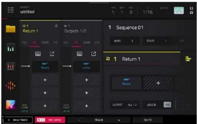
To load a send/return effect to a return in Main Mode:
- Tap the Track header and use the data dial or +/- buttons to change tracks until you reach the Return 1-4 buses. Alternatively, use the Track -/+ buttons at the bottom of the screen.
- Use the Inserts boxes to add or view inserts effects. Tap the + icon in an empty slot to add a new effect. Tap an insert slot with a loaded effect to view the effect's controls.
You can also add send/return effects using the Mixer Strips in Main Mode.

To load a send/return effect to a return in the Channel Mixer:
- In the Channel Mixer, swipe left to show the Returns (between the Submixes and Main Outputs).
- Tap the Effects tab at the bottom of the screen.
- Tap an insert slot to open the effects window and use it to load or edit effects. You can also tap the Inserts button to open the Inserts window, where you can load, change, and enable or disable the effects.

To set the return level:
- In the Channel Mixer, swipe left to show the Returns (between the Submixes and Main Outputs).
- Tap the Volume or Pan & Volume tab in the lower-left corner.
- In the screen, tap the track that corresponds to the desired return.
- Use the level slider in the channel strip to adjust the level of the currently selected return. To make finer adjustments, double-tap the level slider on the screen and adjust the larger version of the slider that appears.
Pads and Keygroups
You can set the send levels for individual pads in Main Mode, Track Edit Mode, or the Pad Mixer.


To set the send levels for a pad or keygroup in Main Mode:
- Use the Track field to select the track that uses the desired pad or keygroup.
- If the channel strip is not already shown, tap the icons at the top of the channel strips to expand them.
- For pad effects, tap the single-pad / four-squares icons in the bottom-right corner of the Track/Arrangement Section to switch from showing the track channel strip to the pad channel strip.
For keygroup effects, tap the single-pad / keyboard icons in the bottom-right corner of the Track/Arrangement Section to switch from showing the track mixer strip to the keygroup mixer strip. - Press a pad to select it or its corresponding keygroup.
- Tap the SEND header to show the insert effects controls in the channel strip.
- Use the Send knobs to set the send level for each return. To make finer adjustments, double-tap the knob on the screen and adjust the larger version of the knob that appears.
![TRACK Trap-Kit-Default A13 INSERTS 1 NO EFFECT 2 Reverb Medium [2 in 2 out] 3 NO EFFECT 4 NO EFFECT GLOBAL SAMPLES AMP ENV MODES EFFECTS SEND 1 4.1 SEND 2 0 SEND 3 0 SEND 4 0](/content/2026/05/883354/images/da8ec096546785ca146e8288d69ccd006bbe0eff45e3cd3ca79c0172cf13d642.jpg)

To set the send levels for a pad or keygroup in Track Edit Mode:
- While editing the desired track in Track Edit Mode, press the desired pad to select it or the corresponding keygroup.
- Tap the Effects tab in the lower-right corner.
Note: This tab is only available for Keygroups when using the Legacy Track Edit view. - Use the Send knobs to set the send level for each return. To make finer adjustments, double-tap the knob on the screen and adjust the larger version of the knob that appears.
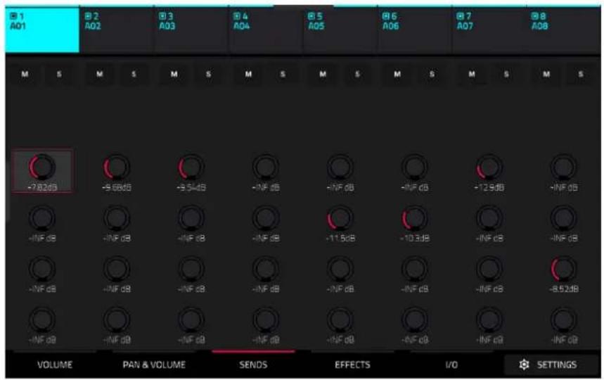
To set the send levels for a pad or keygroup in the Pad Mixer:
- Tap the Sends tab at the bottom of the screen.
- Press a pad to select it or the corresponding keygroup, or tap it on the screen.
- Use the Send knobs to set the send level for each return. To make finer adjustments, double-tap the knob on the screen and adjust the larger version of the knob that appears.
Tracks and Submixes
You can set the send levels for Drum, Keygroup, Plugin, or Audio type tracks, plus Submix 1–8, in Main Mode and the Channel Mixer.

To set the send levels for a track or submix in Main Mode:
- Use the Track field to select the desired track or submix.
- If the channel strip is not already shown, tap the icons at the top of the channel strips to expand them.
- If needed, tap the single-pad / four-squares icons in the bottom-right corner of the Track/Arrangement Section so the track channel strip is selected.
- Tap the SEND header to show the insert effects controls in the mixer strip.
- Use the Send knobs to set the send level for each return. To make finer adjustments, double-tap the knob on the screen and adjust the larger version of the knob that appears.

To set the send levels for a track or submix in the Channel Mixer:
- Tap the Sends tab at the bottom of the screen.
- In the screen, tap the send knob in the desired track.
- Use the Send knobs to set the send level for each return. To make finer adjustments, double-tap the knob on the screen and adjust the larger version of the knob that appears.
Audio Mixdown
The Audio Mixdown screen lets you render and export either the current sequence or song as an audio file.
To open the Audio Mixdown screen, press Menu to open the Menu, then tap Save at the bottom of the screen to open the Save window and select Audio Mixdown. On MPC Key 37, you can also press the Save button to open the Save window.
To open the Audio Mixdown screen in Song Mode, tap Export at the bottom edge of the screen.

Audio Length
Use the Start Bar and End Bar fields to define where the resulting audio file will start and end, respectively.
Use the Audio Tail field to add extra seconds to the end of the resulting audio file. This is useful if you are using effects or samples whose sounds exceed the defined audio length (e.g., long reverb or delay, one-shot samples with long decays, etc.). We recommend using an audio tail of at least a couple of seconds.
Render Source
Check Stereo Output and use the adjacent field to select a pair of outputs (Out 1,2–31,32 and Submix 1–8, availability depends on your MPC hardware type). The mixdown will be taken from these outputs.
Check Separate Tracks to create a mixdown of each track used in the sequence or song.
Important: Each pad or keygroup must have their output routed to Track to be included in the mixdown. This is the typical (and default) setting. See Modes > Pad Mixer > I/O to learn about this.
Render Options
If your Render Source is set to Stereo Output, check Main Inserts to include main insert effects in the mixdown.
If your Render Source is set to Separate Tracks, check Export Submixes to export the submix channel signals as separate files, and Export Returns to export the return channel signals as separate files.
If your Render Source is set to Stereo Output, tap Save as Project Preview to save the sequence or song as a project preview file (which you can play for reference in the Browser). If you check this box, Stereo Output will automatically be checked, as well.
File Formats
Tap WAV, AIFF, MP3, FLAC, or OGG to select the file format of the mixdown.
For WAV and AIFF files, use the Bit Depth field to select a bit depth of 8, 16, or 24 bits, or 32 bits, floating point (32 F). For FLAC files, you can select a bit depth of 16 or 24 bits. For MP3 and OGG files, you can select a Bitrate of 128, 160, 192, or 320 kbps.
Use the Sample Rate field to select a sample rate of 44.1 kHz, 48 kHz, 88.2 kHz, or 96 kHz. In most cases, we recommend selecting 44.1 kHz.

Tap Export to enter the Save screen where you can select a name and location to save your audio mixdown.
Tap Cancel or the ← icon in the upper-left corner to return to the previous screen.
Keyboard Control
The keyboard control screen allows you to edit the functions of the keypad on MPC Key 61 and MPC Key 37.
To access Keyboard Control, press the Keyboard Control button on your MPC Key 61 or MPC Key 37. You can then edit the following parameters.
Keyboard Input
Transpose: This determines the amount of transposition to the keyboard, up to 36 semitones up or down.
MIDI Channel: This determines which MIDI channel (1–16) the keyboard input will use to receive messages.
Aftertouch (Channel Pressure): This determines whether aftertouch is enabled (As Played) or not (Disable).
Note On Velocity: This determines the incoming velocity of note on messages. For velocity that is responsive to your playing, select As played. Alternatively, you can set a fixed velocity for all note on messages, at 12%, 18%, 25%, 31%, 37%, 43%, Half, 56%, 62%, 68%, 75%, 81%, 87%, 93% or Full velocity.
Scale Filter
Filter Input: This determines how specific notes are filtered. Select As Played to apply no filtering, Snap to Scale to shift non-scale notes played to the nearest scale degree, or Filter to Scale to disable non-scale notes from playing entirely.
Root Note: This determines the root note of the set scale.
Scale: This determines the type of scale used for note filtering. The available scales are:
| Chromatic | Pentatonic | Minor | Aeolian | Hungarian | Gypsy |
| Major | Dorian | Locrian | Persian | ||
| Natural Minor Phrygian Blues Major Bebop | |||||
| Harmonic Minor Lydian Flamenco | Whole | Tone | |||
| Pentatonic Major Mixolydian Gypsy | |||||
Internal Keyboard Routing
Keyboard Route: This determines where MIDI data from the keyboard is sent. Select from the following options:
Local Off: Keyboard MIDI data is only sent to the MIDI out. This may be useful if working with external sound modules.
Global: Keyboard MIDI data will always go to the current track.
Tracks: The Keyboard will appear as a port in the list of available track MIDI Inputs.
Global and Tracks: Keyboard MIDI data will go to the current track and be available as a track MIDI input.
External Keyboard Routing
MIDI Output Port: This determines the MIDI port where the keyboard will output MIDI externally.
Keyboard sends MIDI here: Check this box to send all MIDI from the keyboard to the selected MIDI Output port.
MIDI Channel: This determines which MIDI channel (1–16) the keyboard will use to send messages externally.
Minimum Note / Maximum Note: This determines the range of notes that will output MIDI externally.
Keyboard Settings
Velocity Response: This determines how playing the keys translates into velocity values. Select preset Light 1–3, Linear, or Heavy 1–3 responses, or select Custom to create your own response using the following settings:
Velocity Curve: Use this slider to adjust the velocity curve, from -50 to 0 to +50. At negative values, it takes more force to hit higher velocity values; at positive values, it takes less force.
Gain: Use this slider to apply additional gain to the velocity curve, from -20 to 0 to +20. Increasing the gain will make it easier to hit high velocity values, and decreasing it will make it harder.
Black Key Sensitivity: Use this slider to set the sensitivity of the keyboard's black keys, from -20 to 0 to +20.
White Key Sensitivity: Use this slider to set the sensitivity of the keyboard's white keys, from -20 to 0 to +20.
Pedal Settings
Pedal: This determines the pedal input port from MPC Key 61/MPC Key 37. Select Sustain, FS2, or Expression.
Type: This determines the pedal type, either Switch (on/off) or Variable (such as an expression pedal).
Polarity: This determines the polarity of the pedal input. Select Auto, Positive, or Negative. If you are having issues with your pedal, check the settings on your hardware or try adjusting this field for the correct behavior.
CC Assign: This is the MIDI CC assignment the pedal will send. Select Disable, Default (varies depending on the port used), or CC 000-126.
Pitch Bend / Mod Wheel
Pitch Bend: Use this field to select the MIDI function for the keyboard pitch wheel. Select Disable, Default - Pitch Bend, or CC 000-126.
Mod Wheel: Use this field to select the MIDI function for the keyboard modulation wheel. Select Disable, Default – CC 001: Modulation, or CC 000–126.
Global Pitch Bend Settings
Global Pitch Bend: Check this box to override the pitch bend settings of all programs, so that those with pitch bend disabled or set to different ranges will only use the Global Range instead. When unchecked, all programs may use their individual pitch bend settings.
Range Up/Range Down: Use these sliders to set the range of the pitch bend in semitones.
Touch Strip
To use the touch strip with MPC Key 61 or MPC Key 37:
- Press the Touch Strip button to cycle through the available Touch Strip modes, or press and hold Touch Strip to quickly select a mode from the touchscreen:
• Q-Link • Mod Wheel
- Pad Level
- Sustain
- Track Level
- Expression
- Touch FX
- Crossfader
- Notes
- Off
- Pitch Bend
You can also press Touch FX to instantly select TouchFX mode for the Touch Strip.
You can also set the default Touch Strip mode in the Hardware menu of the Preferences.
- Press your finger on the touch strip and move it up and down as an expressive control for the selected parameter.
- Press and hold Shift and press the Touch Strip or Touch FX buttons to configure settings for each mode, if available. See below to learn more.
Q-Link
Select this mode to use the touch strip as a Q-Link control.
To configure the Q-Link settings, press and hold Shift and press the Touch Strip button to open the Touch Strip Q-Link window in the software.
Q-Link: Use this field to select which Q-Link is controlled by the touch strip (1–16). You can also press one of the 16 pads to select that Q-Link while the Touch Strip Q-Link window is open in the software.
Pad Level
Select this mode to use the touch strip to control the current Pad Level.
Track Level
Select this mode to use the touch strip to control the current Track Level.
TouchFX
TouchFX is specially designed for use the touch strip controller on hardware such as MPC Key 61 and 37, but can be used on any MPC hardware and controlled using the onscreen touch slider or an external MIDI device. The effect you control acts like an insert effect on the selected output.
To load the Touch FX plugin, you can simply press and hold the Touch FX button on MPC Key 61 or 37. A window will appear with the included Touch FX presets. Tap a preset to select it, and it will automatically be added as an insert to the current track.
Alternatively, you can load Touch FX as you would any other insert effect when using other MPC hardware:
- Tap an empty slot in the Inserts section of any channel strip.
- Double-tap an empty insert slot in the Effects window to open the list of plugin effects
- Tap the + or - button to expand the Harmonic category.
-
Select the TouchFX plugin.
-
Tap the pencil icon to open the plugin window, where you can adjust the plugin settings and use the virtual touch strip to control the effect. You can also use the MIDI Learn function to assign the touch strip to an external MIDI device.
To configure the Touch FX settings from an MPC Key:
- Press and hold Shift and press the Touch FX button to open the Touch FX Setup window in the software.
- Use the Touch FX Destination field to select where the Touch FX should be applied. You can select the current Track, a Return, a Submix, or an Output. Click the Insert Touch FX button to add Touch FX to the selected destination.
- Once Touch FX has been inserted, you can press and hold Shift and press the Touch Strip button again to reopen the Touch FX Setup window in the software to configure additional settings:
Touch FX Preset: Use this field to select the desired effect for the touch strip. You can also use the data dial or -/+ buttons to cycle through the presets as shown on the display once Touch FX has been inserted to a destination. The specific parameters for each effect can be set by clicking the Touch FX Setup button at the bottom of the window.
Latch: Check this box to keep the current position on the touch strip even after you release it. The position will remain in place until you touch another part of the XY pad or until you uncheck Latch.
Touch > Wet/Dry: Check this box to use the touch strip to control the Wet/Dry amount in addition to the Assigned Parameter as set by clicking the Touch FX Setup button at the bottom of the window.
Wet/Dry: Use this slider to set the blend the original signal (dry) and the effect signal (wet).
Attack: Use this slider to set the length of the attack phase of the envelope, which is triggered when you make contact with the touch strip. In other words, this determines how long it takes the effect to fully respond to your touch.
Release: Use this slider to set length of the release phase of the envelope, which is triggered when you release the touch strip. In other words, this determines how long it takes the effect to fully deactivate after you release your finger from the touch strip.
Touch FX Setup: Tap this button at the bottom of the window in the software to open the effect plugin setup window to change the parameters for the selected preset.
In this window, you can also use the Assigned Parameter field to select a preset parameter to be controlled by the touch strip. This can be separate from or in addition to controlling the Wet/Dry amount, depending on the Touch > Wet/Dry setting.
To close the Touch FX Setup window, press and hold Shift and press the Touch Strip button again.
Use the controls on the left side of the Touch FX plugin window to adjust the settings for MPC Key's Touch Strip control. For other hardware, you can control the Touch Strip by assigning it to a MIDI control or by using the virtual touch strip on the touchscreen.
Touch Strip: This strip represents the MPC Key's touch strip control, and can also be controlled manually by clicking and dragging from the software, tapping and dragging from a hardware touchscreen, or by assigning it a MIDI control. Use this to control the selected Touch FX.
Touch Enable: Tap this box to enable touch control for the currently selected Touch FX.

Assigned Parameter: Use this field to select a preset parameter to be controlled by the touch strip. This can be separate from or in addition to controlling the Wet/Dry amount, depending on the Touch > Wet/Dry setting.
Touch Value: Use this slider to control the value of the Assigned Parameter controlled by the touch strip.
Wet Amount: Use this slider to set the blend the original signal (dry) and the effect signal (wet).
Touch Value / Wet/Dry Lock: Tap the lock icon to use the touch strip to control the Wet/Dry amount in addition to the touch value of the Assigned Parameter.
Touch Attack: Use this slider to set the length of the attack phase of the envelope, which is triggered when you move the touch strip control.
Touch Release: Use this slider to set length of the release phase of the envelope, which is triggered when you release the touch strip control.
Use the controls on the right side of the Touch FX plugin window to select a Touch FX type and adjust its settings. You can also select from the included presets at the top of the window.
See Appendix > Effects & Parameters > Harmonic > TouchFX for a full list of TouchFX preset settings.
Notes
Select this mode to use the touch strip as a control for playing notes in the selected track.
To configure the Note settings, press and hold Shift and press the Touch Strip button to open the Touch Strip Notes Config window in the software.
Root Note: Use this field to set the desired root note of the scale.
Scale: Use this field to set the type of scale.
Octave: Use this field to set the starting octave of the root note.
Velocity: Use this field to set the velocity of the notes played with the touch strip.
Number of Notes: Use this field to set the number of notes covered by the length of the touch strip.
Pitch Bend
Select this mode to use the touch strip as you would a pitch wheel on a typical keyboard to control pitch bend.
To configure the Pitch Bend settings, press and hold Shift and press the Touch Strip button to open the Pitch Bend Settings window in the software.
Relative Mode: When checked, the center pitch is set wherever you first place your finger along the touch strip. When unchecked, the touch strip is fixed with the center being the unchanged noted.
Bend Up Range: Use this field to set the range of the pitch bend up in semitones.
Bend Down Range: Use this field to set the range of the pitch bend down in semitones.
Note: Pitch Bend ranges are only applied to MPC instruments and not to third-party plugins.
Global Pitch Bend: Check this box to override the pitch bend settings of all tracks, so that those with pitch bend disabled or set to different ranges will only use the Global Range instead. When unchecked, all tracks may use their individual pitch bend settings.
Mod Wheel
Select this mode to use the touch strip as you would a mod wheel on a typical keyboard to control the MIDI CC1 modulation control.
Sustain
Select this mode to use the touch strip as you would a sustain pedal on a typical keyboard to enable or disable note sustain. When enabled, notes will continue sounding until sustain is disabled.
Expression
Select this mode to use the touch strip as you would an external expression pedal to control the MIDI CC11 expression control.
Crossfader
Select this mode to use the touch strip as a virtual crossfader. The center point of the touch strip is the center point of the crossfader. Move down to the A side or up to the B side. You can assign parameters to the Crossfader using Q-Link Edit > Crossfader.
Battery Usage
Important: Only MPC Live and MPC Live II may use battery power. MPC X, MPC One, MPC Key 61, and MPC Key 37 must be connected to a power outlet.
Although you can power MPC Live/Live II from a power outlet (using the included power adapter), you can use its internal battery, which typically has four hours of life, depending on CPU and how you're using MPC Live/Live II.
While powering MPC Live/Live II from its internal battery, the battery icon in upper-right corner of the touchscreen will show its current battery life. (The icon beside it indicates whether MPC Live/Live II is in Standalone Mode or Controller Mode.)
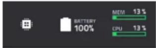
To view MPC Live's system resources (battery life, CPU, and RAM usage), tap the battery icon in upper-right corner of the touchscreen. The System Resources window will appear, showing percentages to indicate the current battery life, CPU, RAM usage (Mem), and storage device space usage.
See System Resources to learn more about the information shown in this window.
To charge MPC Live/Live II's internal battery, connect its power input to a power outlet using the included power adapter. The charging indicator light (behind the vent on the rear panel for MPC Live/Live II) will turn on while charging. When the battery is fully charged or when it is disconnected from a power outlet, then this light will turn off.

bar
| Category | Value (%) | |---|---| | SYSTEM RESOURCES | 100 | | | 6 | | | 25 | | | (Not labeled) |Modes
The MPC hardware has a Menu page that lets you select any one of several modes. This chapter describes the various features and functions of each one.
Click a button below to skip directly to that chapter.

You can also edit the Menu layout by tapping and dragging the menu icons to your preferred location. This is useful for putting your most-used modes in the left-most column so that they are easily accessed in any mode by swiping to the right from the left edge of the touchscreen.
To reset the Menu layout, tap the three-dots icon next to the Sync setting, and then tap Reset Mode Menu.
Main Mode

The enhanced Main Mode gives you an overview of the most-used functions in MPC, improving workflow efficiency and streamlining access to crucial visual feedback and editing functions.
To enter Main Mode, do one of the following:
- Press Main.
- Press Menu, and then tap Main.
Overview
Click or tap on part of the image below to jump directly to that section.
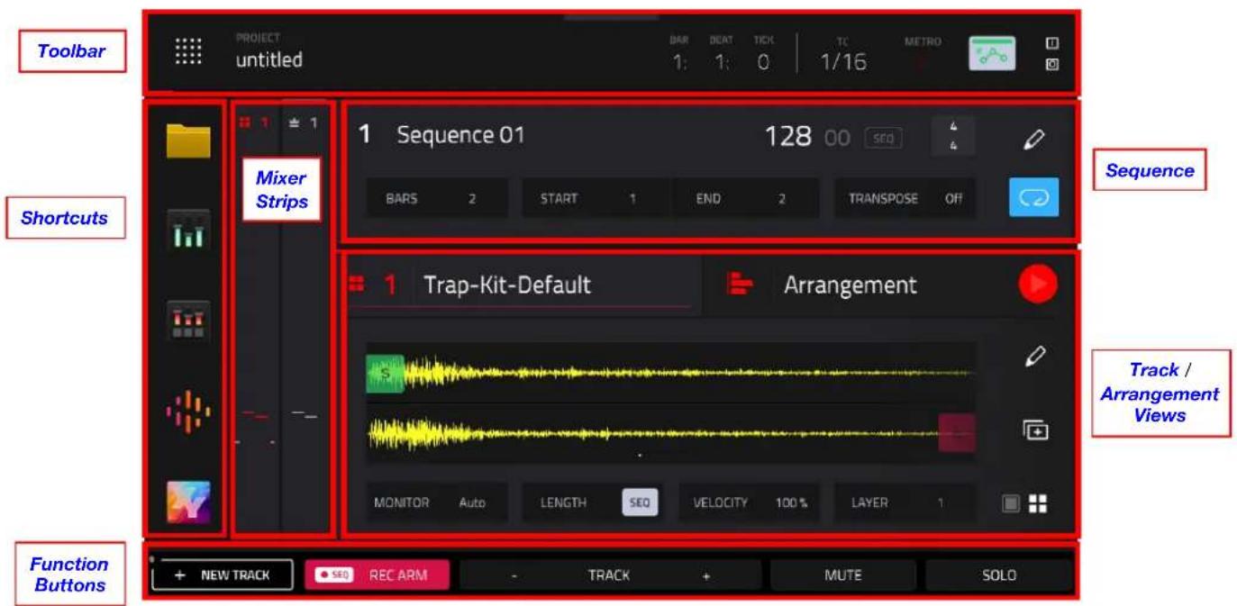
Toolbar
The top of the screen shows the project name and timing information.

The Project field shows the name of the current project.
The time counter shows the current playhead position, in bars:beats:ticks. This is shown in most of the modes. Double-tap to open the Locate window, where you can adjust the playhead position, manage loop and record settings, and quickly jump to specific points in your project.
The TC icon opens the Timing Correct (TC) window, which contains various settings to help quantize the note events in your sequence.
Press and hold Shift and tap the TC icon to enable or disable global timing correct.
The Metro/metronome icon opens the Metronome (Click/Metro) menu, which contains all settings regarding the metronome (click track).
Press and hold Shift and tap the Metro/metronome icon to enable or disable the metronome.
The automation button indicates the global Automation state. This is shown in several modes.
The In and Out boxes indicate your MPC hardware is receiving or sending (respectively) MIDI messages from or to your computer. Tap here to open the MIDI Monitor and view the latest incoming or outgoing MIDI messages.
Shortcuts
The five Mode Icons on the left side of the screen provide shortcuts to some of the most-used modes. By default, these are Browser Mode, Channel Mixer Mode, Pad Mixer Mode, Sounds Mode, and XY Mode.
You can change what mode icons appear here by going to the Menu and tapping and dragging the mode icons to rearrange them. Mode icons dragged into the left-most column will appear in the shortcuts on the Main menu and when sliding out the tab on the left side of the screen in other modes.
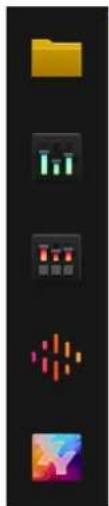
natural_image
Vertical black-and-white image showing five abstract icons: a yellow folder, green bars, red pixelated square, orange dot pattern, and a colorful abstract shape (no text or symbols)Function Buttons

The buttons at the bottom of the screen perform different functions depending on the current mode. In Main Mode, these functions are as follows:
New Track: Tap this button to add a new track to the project.
Rec Arm: Tap this button to arm Sequence recording.
Track -/+ : Tap one of these buttons to switch to the previous or next track, respectively.
Mute: Tap this button to mute the current track.
Solo: Tap this button to solo the current track.
Sequence Section
The Sequence section shows the current sequence and its information.
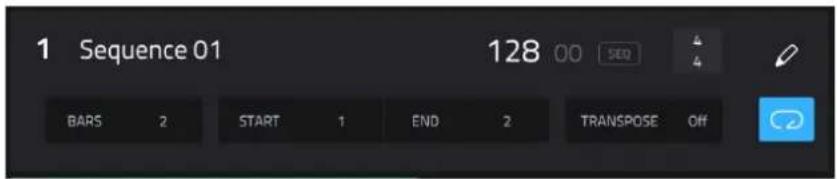
Use Sequence field to select a sequence.
Tap and hold the Sequence name to open the Sequence Settings window.
Use the Name field to edit the Sequence name.
Use the Auto-Select Track field to specify which track is selected when switching sequences. Select None to keep the current track selected when changing sequences, or select a specific track from your project.
Use the BPM field to adjust the tempo of the sequence.
To set whether the sequence follows its own tempo (Sequence) or a global tempo (Global), tap the Sequence/Global button under the BPM field. Alternatively, press and hold Shift and Tap.

Tap the Time Signature fields to adjust the time signature of the project. The numerator (top number) indicates the number of beats per bar (1–16). The denominator (bottom number) indicates the note value of each beat (4, 8, 16, 32). Time signature changes apply to all sequences within the project.
Tap Do It to apply the Time Signature change.
Tap Cancel, the X, or anywhere outside the window to close it.
Use the Bars field to adjust the length of the sequence in bars.

The Loop button shows whether the sequence (or a part of it) will loop or not.
To enable or disable looping, tap the button.
To set the start point and end point of loop, tap the Start or End field (respectively) and then use the data dial or the - / + buttons, or double-tap the field and use the numeric keyboard that appears.
Note: The Last Bar value of the Delete Bars and Copy Bars processes depends on the total length of the sequence.
Use the Transpose field to set the transposition (in semitones) of the entire sequence.
To edit the sequence, tap the pencil icon on the right edge of the section. The Sequence Edit window will open.

You can use any of these functions as described below, though there are fewer options for audio tracks than for MIDI tracks.
The Erase function erases all or part of a track in a specific sequence.
Use the Sequence field to select the sequence you want to erase.
Use the Track field to select the track you want to erase within the sequence.
Use the Bar, Beat, and Tick fields to set the time range of the sequence you want to erase. The left fields set the start of the time range, and the right fields set the end of the time range.
To select what types of events you erase, select one of the Erase options:
All erases all pad events from the designated time range and reset all of its settings.
Automation erases only automation from the designated time range.
Note erases only specific pad events from the designated time range. In the diagram of the eight pad banks that appears, press each pad in each bank to select or deselect its notes. This option is available only for MIDI tracks, not audio tracks.
Except Note erases everything except note events from the designated time range. This option is available only for MIDI tracks, not audio tracks.


Tap Do It to confirm your choice.
Tap Cancel, the X, or anywhere outside the window to return to the previous screen.
The Clear All function erases all events from the sequence and resets all of its settings.
Tap Clear All to confirm your choice.
Tap Cancel to return to the previous screen.

The Clear Events function only erases all events from the sequence.
Tap Clear Events to confirm your choice.
Tap Cancel to return to the previous screen.

The Trim function immediately crops the sequence to the length of the Bars value.
The Transpose function transposes a range of events on a track in a sequence. The events within that range will shift accordingly in the Grid View. This option is available for MIDI tracks only.
Use the Sequence field to select the sequence you want to transpose.
Use the Track field to select the track you want to transpose within the sequence.
Use the two sets of Bar, Beat, and Tick fields to set the time range of the sequence you want to transpose. The left fields set the start of the time range, and the right fields set the end of the time range.
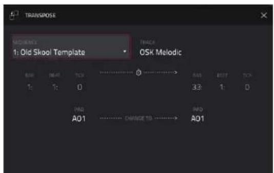
For drum tracks, use the two Pad fields to select the “source” pad (whose events you want to move) and “destination” pad (where the events will be placed). Tap each field and then press the desired pad.
For keygroup tracks, plugin tracks, and MIDI tracks, set the range and amount of transposition:
Range: Use the two Note fields to set the range of notes of the events you want to transpose. Note events within this range will be transposed, while note events outside of this range will remain unchanged.
Transpose: Use this field to set how many semitones up or down you want to transpose the note events.
Tap Do It to confirm your choice.
Tap Cancel, the X, or anywhere outside the window to return to the previous screen.
The Delete Bars function removes a range of bars from a sequence.
Use the Sequence field to select the sequence whose bars you want to delete.
Use the First Bar and Last Bar fields to set the range of bars you want to delete. The bar in each field and all bars in between them will be deleted.
Tap Do It to confirm your choice.
Tap Cancel, the X, or anywhere outside the window to return to the previous screen.

The Insert Bars function adds empty bars to a sequence at a specified point.
Use the Sequence field to select the desired sequence.
Use the # of Bars field to set how many bars you will insert.
Use the Before Bar field to set where you will insert the bars. The bars will be inserted before this one.
Tap Do It to confirm your choice.
Tap Cancel, the X, or anywhere outside the window to return to the previous screen.

The Half Length function will immediately halve the length of the sequence (without deleting any note events).
The Double Length function will immediately double the sequence and copy all events from the first half to the second half.
The Copy Sequence function copies the contents of one sequence to another.
Use the Copy Contents of Sequence field to select the “source” sequence. This is the sequence whose events you want to copy.
Use the Over Contents of Sequence field to select the "destination" sequence.
This is the sequence where the source sequence will be copied.
Tap Do It to confirm your choice.
Tap Cancel, the X, or anywhere outside the window to return to the previous screen.

The Copy Bars function copies a range of bars from a sequence and adds them to another at a specified point.
Use the From Sequence field to select the "source" sequence. This is the sequence whose bars you want to copy.
Use the First Bar and Last Bar fields to set the range of bars to copy in the source sequence.
Use the To Sequence field to select the “destination” sequence. This is the sequence where the source sequence bars will be copied.
Use the After Bar field to set where you want to add the copied bars. The copied bars will be inserted after this one.

Use the Copies field to set how many instances of the copied bars you want to add.
Tap Replace to overwrite the destination sequence.
Tap Merge to add the events to the destination sequence without erasing anything.
Tap Cancel, the X, or anywhere outside the window to return to the previous screen.
The Copy Events function copies a range of events or selected audio track regions from a sequence and adds them to another at a specified point.
Use the From Sequence field to select the "source" sequence. This is the sequence whose content you want to copy.
Use the From Track field to select the "source" track. This is the track whose content you want to copy.
The Pads or Notes field will specify the pads or notes from which to copy events. By default, this will be set to All to copy all events in the current track. To select specific pads or notes, press the corresponding pads on your MPC hardware.
Use the Selection field to set what notes are copied from the chosen time range. Copy All Events will copy and paste all events in the track. Copy Only Selected Events will copy and paste only the events that are currently selected. This field is available for MIDI tracks only.
Use the Bar, Beat, and Tick fields to set the time range of the events or the audio track you want to copy. The left fields set the start of the time range, and the right fields set the end of the time range.
Use the To Sequence field to select the "destination" sequence. This is the sequence where the content of the source sequence will be copied.

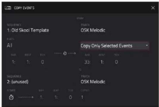
Use the To Track field to select the "destination" track. This is the track where the content of the source track will be copied.
Use the Bar, Beat, and Tick fields to set where you want to add the copied events or audio track. The events or audio track will be added after this point.
Use the Copies field to set how many instances of the copied events or audio track you want to add.
Tap Replace to overwrite the destination sequence.
Tap Merge to add the events to the destination sequence without erasing anything.
Tap Cancel, the X, or anywhere outside the window to return to the previous screen.
Track Section
The Track section displays essential details for the current track type and facilitates track-specific editing operations.

Example Track section while using a Drum track.
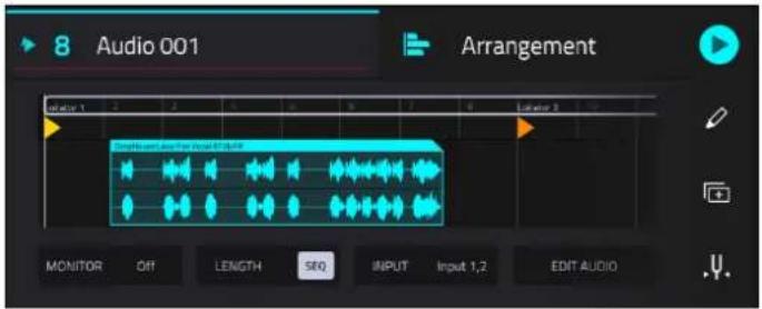
Example Track section while using an Audio track.
The track field shows the track number and its name.
To edit the name of the track, tap and hold on the track name to open the Track Settings window, and then use the Name field.
To change tracks, use the Track -/+ buttons at the bottom of the screen. Alternatively, tap the Track header and use the data dial or +/- buttons.
You can also press and hold Main and a window will appear showing all tracks in your project in a four-by-four layout, mirroring your MPC pads. Tap a track in the window to select, or press the respective pad on your hardware.
From this window, you can also tap Tracks, Submixes, Returns, and Outputs to display the selected track types in the window, and then select one in the same way.
To change track type, tap the track type icon next to the track number, and then select the track type from the menu that appears.
Drum Tracks
To select a pad, simply tap the pad on your MPC hardware.
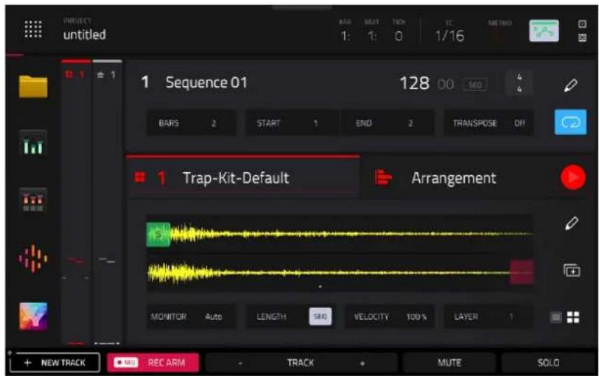
When a sample is loaded to the selected pad:
The waveform displays the sample loaded to the selected pad on the selected layer.
In the waveform preview, pinch in or out to adjust the zoom level. You can also adjust the start (S) marker (if Loop Lock is on), loop marker (if Loop Lock is off), and end (E) marker by tapping and dragging.
Double-tap the waveform preview to open the Samples tab of Track Edit mode.
To change layers, use the Layer field at the bottom of the track section.

If no sample is loaded to the selected pad:
Tap Browse to open the Browser to search for and select a sample to load.
Tap Record to open the Sampler to record and load a new sample. Alternatively, you can record a sample directly to the pad from Main Mode:
- Press the Rec button on your MPC hardware to arm recording.
- Tap an empty pad to arm it for recording. Recording will follow the settings established in the Sampler mode regarding active inputs and threshold. When you are finished recording, tap the pad again. You can also press and hold a pad, and recording will continue as long as the pad is held.
Use the Monitor field to set how your track will be monitored. Double-tap this field to open the menu, or tap to select the field and then use the data encoder or +/- buttons to cycle through its four states:
When set to Off, the track's MIDI input is not monitored, and playback of recorded events will be heard. This setting is useful when using keyboards with Local Control active.
When set to In, the track's MIDI input is always monitored regardless of the track's Record Arm state, and playback from recorded events will not be heard.
When set to Auto, the track's MIDI input is monitored when the track is record armed, and playback of recorded events will be heard.
When set to Merge, the track's MIDI input is always monitored, and playback of recorded events will be heard.
Use the Length field to set how long the track is in beats. When the SEQ button is on, the track length will follow the Sequence length. When this button is off, use the Bars:Beats:Ticks values to set the exact track length.
Tip: This feature lets you maintain tracks of different lengths. For instance, you could play a 1-bar drum sequence repeatedly under a 4-bar bass line.
Use the Velocity field to set how loudly or quietly a track plays relative to its recorded levels. When set to 50%, the track will be played with half the velocity it was originally played. When set to 200%, the track will play twice as loud. The maximum velocity level is still 127, though. This setting will also affect pads or other MIDI-related input for that specific track.
Use the Layer field to select which of the eight available sample layers are shown. The layer number is shown here, and the dots in the waveform preview indicate the layer shown.
Tap the pencil icon to open the Track Edit window. See Track Edit to learn more.
Tap the Duplicate Track icon to immediately create an identical track on a new track.
Tap the pad / four pads icons to swap the Mixer Channel Strip between showing Track and Pad settings. See Mixer Strips to learn more.
Keygroup Tracks

The waveform displays the sample loaded to the selected pad on the selected layer.
In the waveform preview, you can adjust the start (S) marker (if Loop Lock is on), loop marker (if Loop Lock is off), and end (E) marker by tapping and dragging.
Double-tap the waveform preview to open the Samples tab of Track Edit mode.
Use the Monitor field to set how your track will be monitored. Double-tap this field to open the menu, or tap to select the field and then use the data encoder or +/- buttons to cycle through its four states:
When set to Off, the track's MIDI input is not monitored, and playback of recorded events will be heard. This setting is useful when using keyboards with Local Control active.
When set to In, the track's MIDI input is always monitored regardless of the track's Record Arm state, and playback from recorded events will not be heard.
When set to Auto, the track's MIDI input is monitored when the track is record armed, and playback of recorded events will be heard.
When set to Merge, the track's MIDI input is always monitored, and playback of recorded events will be heard.
Use the Length field to set how long the track is in beats. When the SEQ button is on, the track length will follow the Sequence length. When this button is off, use the Bars:Beats:Ticks values to set the exact track length.
Tip: This feature lets you maintain tracks of different lengths. For instance, you could play a 1-bar drum sequence repeatedly under a 4-bar bass line.
Use the Velocity field to set how loudly or quietly a track plays relative to its recorded levels. When set to 50%, the track will be played with half the velocity it was originally played. When set to 200%, the track will play twice as loud. The maximum velocity level is still 127, though. This setting will also affect pads or other MIDI-related input for that specific track.
Use the Transpose field to set the transposition (in semitones) of the entire track.
Tap the pencil icon to open the Track Edit window. See Track Edit to learn more.
Tap the Duplicate Track icon to immediately create an identical track on a new track.
Tap the pad perform icon to open the Pad Perform window, where you can adjust what notes or chords are played by the pads on your MPC hardware.
Tap the pad / keyboard icon to swap the Mixer Channel Strip between showing Track and Keygroup settings.
Plugin Tracks

Use the Plugin field to select the plugin the track is using. In the screen that appears, you can tap the Type or Manufacturer button at the bottom of the screen to enable or disable sorting of your plugins by type or maker.
Use the Preset field to select a preset (if any) within the plugin the track is using.
Tap the plugin preview icon to open Track Edit Mode and view the plugin interface.
Use the MIDI Ch field to select the MIDI channel over which the track sends its MIDI data.
Use the Monitor field to set how your track will be monitored. Double-tap this field to open the menu, or tap to select the field and then use the data encoder or +/- buttons to cycle through its four states:
When set to Off, the track's MIDI input is not monitored, and playback of recorded events will be heard. This setting is useful when using keyboards with Local Control active.
When set to In, the track's MIDI input is always monitored regardless of the track's Record Arm state, and playback from recorded events will not be heard.
When set to Auto, the track's MIDI input is monitored when the track is record armed, and playback of recorded events will be heard.
When set to Merge, the track's MIDI input is always monitored, and playback of recorded events will be heard.
Use the Length field to set how long the track is in beats. When the SEQ button is on, the track length will follow the Sequence length. When this button is off, use the Bars:Beats:Ticks values to set the exact track length.
Tip: This feature lets you maintain tracks of different lengths. For instance, you could play a 1-bar drum sequence repeatedly under a 4-bar bass line.
Use the Velocity field to set how loudly or quietly a track plays relative to its recorded levels. When set to 50%, the track will be played with half the velocity it was originally played. When set to 200%, the track will play twice as loud. The maximum velocity level is still 127, though. This setting will also affect pads or other MIDI-related input for that specific track.
Tap the pencil icon to open the Track Edit window. See Track Edit to learn more.
Use the Transpose field to set the transposition (in semitones) of the entire track.
Tap the Duplicate Track icon to immediately create an identical track on a new track.
Tap the Pad Perform icon to open the Pad Perform window, where you can adjust what notes or chords are played by the pads on your MPC hardware.
MIDI Tracks

Use the MIDI Input Port field to select the port over which the track receives its MIDI data.
Use the MIDI Output Port field to select the port over the track sends its MIDI data.
Use the MIDI Output Ch field to select the MIDI channel over which the track sends its MIDI data.
Use the Program Ch field to select the program change message the track sends out.
Use the Bank LSB and Bank MSB fields to select the messages for Least Significant Byte and Most Significant Byte (respectively) that the track sends out.
Use the Monitor field to set how your MIDI track will be monitored. Double-tap this field to open the menu, or tap to select the field and then use the data encoder or +/- buttons to cycle through its four states:
When set to Off, the track's MIDI input is not monitored, and playback of recorded events will be heard. This setting is useful when using keyboards with Local Control active.
When set to In, the track's MIDI input is always monitored regardless of the track's Record Arm state, and playback from recorded events will not be heard.
When set to Auto, the track's MIDI input is monitored when the track is record armed, and playback of recorded events will be heard.
When set to Merge, the track's MIDI input is always monitored, and playback of recorded events will be heard.
Use the Length field to set how long the track is in beats. When the SEQ button is on, the track length will follow the Sequence length. When this button is off, use the Bars:Beats:Ticks values to set the exact track length.
Tip: This feature lets you maintain tracks of different lengths. For instance, you could play a 1-bar drum sequence repeatedly under a 4-bar bass line.
Use the Velocity field to set how loudly or quietly a track plays relative to its recorded levels. When set to 50%, the track will be played with half the velocity it was originally played. When set to 200%, the track will play twice as loud. The maximum velocity level is still 127, though. This setting will also affect pads or other MIDI-related input for that specific track.
Use the Transpose field to set the transposition (in semitones) of the entire track.
Tap the pencil icon to open the Track Edit window. See Track Edit to learn more.
Tap the Duplicate Track icon to immediately create an identical track on a new track.
Tap the Pad Perform icon to open the Pad Perform window, where you can adjust what notes or chords are played by the pads on your MPC hardware.
CV Tracks

Use the Melodic / Drum buttons to set the CV operation type.
When set to Melodic type, you can adjust the Note Priority (Note/Last), the CV Port, the Gate Port, the modulation wheel port (Mod Wheel Port), and Velocity Port.
When set to Drum type, you can configure any Pad to output on any CV Port, as well setting the Data Type.
Use the Monitor field to set how your track will be monitored. Double-tap this field to open the menu, or tap to select the field and then use the data encoder or +/- buttons to cycle through its four states:
When set to Off, the track's input is not monitored, and playback of recorded events will be heard. This setting is useful when using keyboards with Local Control active.
When set to In, the track's input is always monitored regardless of the track's Record Arm state, and playback from recorded events will not be heard.
When set to Auto, the track's input is monitored when the track is record armed, and playback of recorded events will be heard.
When set to Merge, the track's input is always monitored, and playback of recorded events will be heard.
Use the Length field to set how long the track is in beats. When the SEQ button is on, the track length will follow the Sequence length. When this button is off, use the Bars:Beats:Ticks values to set the exact track length.
Tip: This feature lets you maintain tracks of different lengths. For instance, you could play a 1-bar drum sequence repeatedly under a 4-bar bass line.
Use the Velocity field to set how loudly or quietly a track plays relative to its recorded levels. When set to 50%, the track will be played with half the velocity it was originally played. When set to 200%, the track will play twice as loud. The maximum velocity level is still 127, though. This setting will also affect pads or other MIDI-related input for that specific track.
Use the Transpose field to set the transposition (in semitones) of the entire track.
Tap the pencil icon to open the Track Edit window. See Track Edit to learn more.
Tap the Duplicate Track icon to immediately create an identical track on a new track.
When the CV track type is set to Melodic, tap the Pad Perform icon to open the Pad Perform window, where you can adjust what notes or chords are played by the pads on your MPC hardware.
Audio Tracks
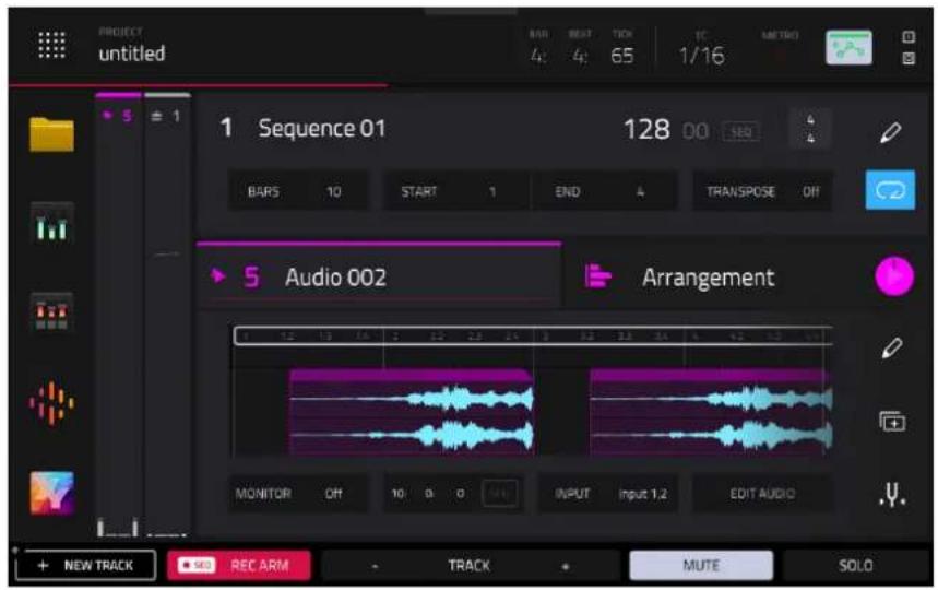
Tap and drag the Loop marker to adjust the loop length. Dragging from either end will extend or shorten the loop. Dragging from the middle of the loop marker will move the entire loop.
Double-tap the audio sample timeline to open Grid View for the audio track, where you can edit the audio regions.
Use the Monitor field to set how your audio track will be monitored. Double-tap this field to open the menu, or highlight this field and then use the data dial or +/- buttons to choose from the following:
When set to Off, you will never hear any incoming audio.
When set to In, you will hear incoming audio whether or not the track is record-enabled.
When set to Auto, you will hear incoming audio while the track is record-enabled only.
When set to Merge, the track's input is always monitored, and you will hear playback of audio.
Use the Length field to set how long the track is in beats. When the SEQ button is on, the track length will follow the Sequence length. When this button is off, use the Bars:Beats:Ticks values to set the exact track length.
Tip: This feature lets you maintain tracks of different lengths. For instance, you could play a 1-bar drum sequence repeatedly under a 4-bar bass line.
Use the Input field to select which inputs the audio track will use.
Use the Edit Audio button to open the audio Grid View for the audio track, where you can edit the audio regions.
Tap the pencil icon to open the Track Edit window. See Track Edit to learn more.
Tap the Duplicate Track icon to immediately create an identical track on a new track.
Tap the Tuner icon to open the built-in Tuner, which allows you to easily tune any connected audio source.
Buses
In addition to the previous track types, you can also view and edit bus tracks including Submixes, Returns, and Outputs in this section.


Use the Inserts boxes to add or view inserts effects. Tap the + icon in an empty slot to add a new effect. Tap an insert slot with a loaded effect to view the effect's controls.
Use the Output field to set the output routing for the bus. This is not available when viewing the Outputs.
Use the Length field to set how long the track is in beats. When the SEQ button is on, the track length will follow the Sequence length. When this button is off, use the Bars:Beats:Ticks values to set the exact track length.
Tip: This is useful when creating automation on your bus track.
Tap the Inserts button to open a window where you can load, change, and enable or disable the effects.
Tap the Load FX Rack to load a factory or user-saved FX rack to the track.
Track Edit

To edit the track, tap the pencil icon on the right edge of the section. The Track Edit window will open.
To return to Main Mode, tap Cancel or the left arrow ( ) in the upper-left corner of the screen. Alternatively, press Main.
The available functions in the Track Edit depend on the type of track selected. The following functions are available for all tracks:

The Copy Track function copies the contents of one track to another.
Use the Copy Contents of Track field to select the "source" track. This is the track whose events you want to copy.
Use the Over Contents of Track field to select the "destination" track. This is the track where the source track will be copied.
Tap Do It to confirm your choice, or tap Cancel to cancel and return to Main Mode.
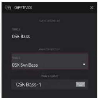
The Duplicate Track function immediately creates an identical track on a new track.
The Duplicate Track with Events function immediately creates an identical track, including all existing events on that track, on a new track.
The Delete Track function instantly removes the track and all of its contents.
Additionally, when a Drum track is selected, the following options are available.

The Merge Pads function allows you to merge samples and settings from two drum tracks together.
Use the From Track field to select the track from which the pads will be copied.
Use the Into Track field to select the track to which the copied pads will be merged.
Check the Start on next bank field to merge the samples and settings at the start of the next unused bank.
Tap Do It to merge the pads, or tap Cancel to close the window and return to the previous screen.
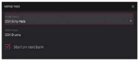
The Merge Tracks function lets you combine the contents of one drum track into another.
Use the From Track field to select the track whose contents will be copied.
Use the Into Track field to select the track to which the copied track will be merged.
Check the Include program and pad parameters field to merge the track settings into the new track.
Tap Do It to merge the tracks, or tap Cancel to close the window and return to the previous screen.
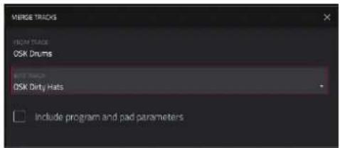
The Copy Pads function allows you to copy one or more pads from one drum track to another.
Use the Copy Type menu to select whether you want to copy an individual Pad, a Bank of pads, or a Range of pads. Use the fields that appear to select the Pad, From Bank or Start/End Pads that will be copied.
Use the From Track field to select the track from which the pads are copied.
Use the To Track field to select the track to which the copied pads are added.
Use the Pad, To Bank or Start Pad fields to set the starting point where the copied pads are added.
Tap Apply to copy the pads and keep this window open.
Tap Do It to copy the pads and close the window, or tap Close to close the window without making any changes.

The Explode Track function immediately breaks down a Drum track containing samples and events into multiple new tracks, making it easier to mute individual drum elements using Track Mute Mode. Each new track will keep the pad and track insert effects of the original source track. Where pads with events are assigned to a mute group, those pads are copied to a single track.
The Edit Pad Note Map function lets you assign specific MIDI notes to your MPC hardware pads.
Use the Pad field to select a pad, or press the pad on your hardware.
Use the MIDI Note field to set the desired MIDI note value for the pad.
Use the Presets buttons to assign a preset layout to the pads: Chromatic C1 (an ascending chromatic scale, beginning with C1), Chromatic C-2 (an ascending chromatic scale, beginning with C-2), or Classic MPC (the default MIDI note map of classic MPCs).
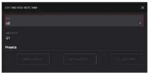
When a Keygroup track is selected, you can also access the Merge tracks function.

The Merge Tracks function lets you combine the contents of one keygroup track into another.
Use the From Track field to select the track whose contents will be copied.
Use the Into Track field to select the track to which the copied track will be merged.
Check the Include program and pad parameters field to merge the track settings into the new track.
Check the Increment layers by 1 to append the From Track's keygroup sample layer(s) to the next available layer in the Into Track.
Tap Do It to merge the tracks, or tap Cancel to close the window and return to the previous screen.

Arrangement Section
The Arrangement section displays recorded events on the linear timeline and provides easy access to its editing functions.
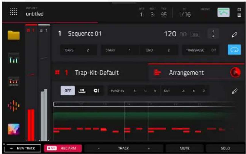
Tap the play icon to begin playback of the linear arrangement.
Use the Auto Record buttons to determine how punch in auto recording is enabled:
Off: Auto Record at Punch In is turned off.
In: Auto Record at Punch In is enabled. Once playback reaches the Punch In point, recording will begin automatically.
Loop Start: Once playback reaches the Loop Start point, recording will begin automatically.
Use the Punch In and Out field to set the start and end points for Punch In Auto Recording.
Double-tap on the linear timeline to open Grid View displaying the current track.
Tap the pencil icon to open the Arrangement Edit options for the arrangement.
The following function is available for all track types:
The Clear function erases all events from the sequence for the current track.
Tap Clear to confirm your choice.
Tap Cancel to return to the previous screen.
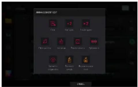
The following functions are available for all track types except Audio:
The Half-Speed function immediately doubles the lengths of all note events in the arrangement as well as the distance between them. In other words, all notes are spread further apart so the arrangement sounds like it is playing at half of the previous speed. This does not actually affect the pitches of notes or the tempo.
The Double-Speed function immediately halves the lengths of all note events in the arrangement as well as the distance between them. In other words, all notes are pressed closer together so that the arrangement sounds like it is playing at twice the previous speed. This does not actually affect the pitches of notes or the tempo.
The Pitch Quantize function forces the pitches of MIDI note events into a specific scale.
Use the Root Note field to select the desired root note of the scale.
Use the Scale field to select a type of scale.
To determine which note events will be quantized, tap the Only apply to selected events checkbox.
When on, only the currently selected note events will be quantized.
When off, all pitches in the current track will be quantized.
Use the Start Note and End Note fields to set lowest-possible and highest-possible pitches where the quantized note events will be placed (respectively). If a note event is originally outside of this range, it will be forced to the nearest pitch (within the scale) inside the range.
Tap Do It to confirm your choice, or tap the X, Cancel, or anywhere outside the window to cancel and return to the previous screen.
![PITCH QUARTIZE Setup ROOT NOTE C SCALE Major Note Input Filter [ ] Only apply to selected events Output Note Range Quantized notes will be moved up/down by an octave to fit into this note range. F-2 G8](/content/2026/05/883354/images/f1b66aa71cf42e97029fbd8374c9d70769c4b5932bf06b8d9054c048dae12139.jpg)
The Humanize function applies randomization to the timing, length, and/or velocity of note events.
Tap the Humanize Time checkbox to select whether or not humanization will be applied to the timing of note events.
Use the Amount (Pulses) slider to select the maximum number of pulses by which the timing of an event will be adjusted.
Use the Eagerness slider to set how dramatically the humanization effect is applied to the timing. Negative values correspond to playing “ahead of the beat” while positive values correspond to playing “behind the beat.”
Tap the Humanize Note Length checkbox to set whether or not humanization will be applied to the duration of note events.
Use the Length (%) slider to set how dramatically the humanization effect is applied to note lengths.
Tap the Humanize Velocity checkbox to set whether or not humanization will be applied to the velocities of note events.
Use the Strength (%) slider to set how dramatically the humanization effect is applied to note velocities.
Tap the Only Apply to Selected Events checkbox to determine which notes will use these humanization values:
When on, just the currently selected notes will be humanized.
When off, all notes in the arrangement will be humanized.
Tap Apply to apply humanization and keep this window open.
Tap Do It to apply humanization and close the window.
Tap Close, the X, or anywhere outside the window to close the window without making any changes.

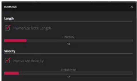
The Random Events function creates random melodic or drum patterns in the current arrangement.
Use the Event Type field to select Drum Events or Melodic Events to select the type of events you want to create.
Use the Replace field to select how the events will be created relative to the existing events on the track:
Replace All Events: Select this option to replace all events in the arrangement with the randomly generated ones.
Replace Events in Note Range: Select this option to replace all events in the designated note range in the arrangement with the randomly generated ones. Use the Bank or Start Pad and End Pad menus to set the note range for drum events or the Start Note and End Note menus to set the note range for melodic events.
Add to Existing Events: Select this option to add the randomly generated events to the arrangement without replacing or overwriting the existing ones.
Use the Pattern Size (Bars) field to set how many bars the events will use. The highest possible value is the number of bars in the current arrangement.
Use the Note Length field to select the duration of the events. (This feature is nonfunctional if Legato is enabled while generating melodic events.)
Tap Apply to generate the events and keep this window open.
Tap Do It to generate the events and close the window.
Tap Close, the X, or anywhere outside the window to close the window without generating any events.

The Split Events process divides note events into an equal number of parts.
Use the Into slider to select the number of parts the event(s) will be split into.
Tap the Only selected events checkbox to apply the process only to currently selected events. When unchecked, all events will be split.

The Convert to Progression function creates a custom Progression from a melodic MIDI track that you can use to perform with Progressions Note mode.
Use the Progression fields to set the parameters of the new Progression:
Use the Name field to set the progression name.
Use the Root Note field to set the root note.
Use the Scale Type field to set the scale type.
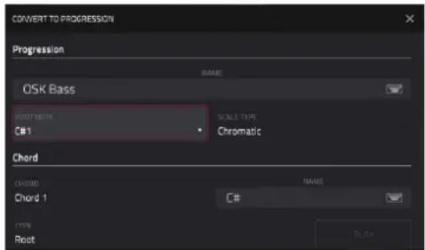
Use the Chord fields to set the parameters for the chords in the Progression:
Use the Chord field to select a chord from the progression to edit.
Use the Name field to rename the selected chord.
Use the Type field to set the type of chord: Root, Normal or Below Root.
Tap the Play button to play the selected chord.
Tap Do It to convert the progression and close the window.
Tap Close, the X, or anywhere outside the window to close the window and return to the previous screen.
The following functions are available for Drum, Keygroup, and Plugin tracks:
The Bounce to Sample function renders the current track in the arrangement as an audio sample and places it in the project's sample pool. By default, it will be named Bounce and appended with the track name.
Use the Audio Tail field to set the amount, in seconds, of extra time added to the end of the resulting audio files.
The Bounce to Audio Track function renders the current track in the arrangement and adds it as a new audio track in the project. The Main Mode will automatically switch to the Audio track. By default, it will be named Bounce and appended with the track name. This function does not work for MIDI tracks or CV tracks.
Use the Audio Tail field to set the amount, in seconds, of extra time added to the end of the resulting audio files.
The following functions are available for Audio tracks only:
The Flatten and Flatten Elastique functions flatten the audio track when transport playback is stopped, rendering all the edits and regions within the arrangement to a single new audio file. The Elastique Pro algorithm can be used for time-stretching or pitch-shifting, providing higher-quality results with less artifacts than MPC's standard algorithm.
Mixer Strips
On the left edge of the screen, next to the five mode icons, are the XL Channel Strips, which allow you to effortlessly manage all your mixing tasks with access to important settings for the current pad, track, and main output.
To show or hide the mixer channel strips, tap the icons at the top of the condensed strips.

On the left side is the track or pad channel strip. When viewing a Drum track, you can tap the single-pad / four-squares icons in the bottom-right corner of the Track/Arrangement Section to cycle between track or pad mixer strips. When viewing a Keygroup track, tap the single-pad / keyboard icons in the same location to toggle between track or keygroup mixer strips.


The right side will dynamically adjust to display relevant information based on your actions. For example, selecting a send option in the left channel strip will prompt the right channel strip to show the corresponding return channel. When a track is shown on the left side, this will show the main output, and when a pad is shown on the left side, this will show the corresponding track. This allows for seamless access to audio routing options and streamlined navigation.
Both mixer channel strip types feature four views:
LVL: This view contains common mixer parameters.
The Level meter displays track volume and incoming MIDI. Use the white line to adjust the track level.
Use the pan slider to adjust the track panning.
Tap the Mute button to mute the track.
Tap the Solo button to solo the track, muting all other tracks. (Not shown for Main Output)
Tap the Automation button to toggle between the three automation states: Read (R), Write (W), and Off. (Not shown for Pad.)
Tap the Record button to arm the sequence for recording. (Not shown for Pad or Main Output)
When viewing a Pad channel strip, the first field shows the current pad number. Press a pad or tap the field to select a different pad.
Tip: This is useful for mixing your pads without having to enter the Pad Mixer.


FX: This view displays insert effects.
Tap the FX Racks icon to load an FX rack.
Tap the expand window icon to open the Inserts window, where you can load, change, and enable or disable the effects. Here, you can also easily rearrange insert effects using the arrow buttons to shift their order.
Tap an empty insert slot (indicated by a +) to open the plugin browser window.
If an effect is loaded, tap the insert slot to open the plugin effect interface.

SEND: This view displays Sends 1–4. (Not shown for Main Output)
Use the Send knobs to adjust the send level. When a Send knob is adjusted, the associated Return track will be shown in the adjacent mixer strip.

I/O: This view displays routing options. (Not shown for Main Output)
Tap the Monitor button to change the monitor behavior for the track. When the track is being monitored, the meter on the left side will show the incoming audio level or MIDI velocity.
Use the MIDI Input and Channel fields to configure the MIDI input settings. (Not available for Audio tracks.)
Use the Send To field to send the track's MIDI output to another track. (Not available for Audio tracks.)
Use the MIDI Output and Channel fields to configure the MIDI output settings. (Not available for Audio tracks.)
Use the Audio In field to configure the input source of the external audio signal, which you can set to a pair of inputs (Input 1,2) or a single input (Input 1, Input 2). (Audio tracks only.)
Use the Audio Out field to configure where the track or pad is routed, which you can set to a submix (Sub 1–8), a pair of outputs (Out 1,2–Out 3,4), or a single output (Out 1–4). (Audio, Drum, and Plugin tracks only.)
Note: When set to a mono channel, the left and right channels are summed post-pan knob. If the pan knob is set to the center position, the left and right channels will be summed and padded. If the pan knob is set to the maximum left or right positions, only the respective channel will be sent to the output.

When viewing a Pad Channel strip, the following options are also available:
Use the MIDI Out Enabled field to determine when a MIDI note is sent to the MIDI Output. This can be used for triggering external gear, lighting, or video systems. Select Never (no MIDI note is sent), Always (MIDI note is sent every time the pad is triggered), or When Empty (MIDI note is only sent if the pad has no internal sample).
Use the MIDI Out Note to select the specific MIDI note to send for the selected pad.
Use the MIDI Out Channel to select the MIDI Channel where the output is sent.

Browser

The Browser lets you navigate your MPC hardware's internal and external hard disks to load samples, sequences, songs, etc. Using filter buttons and user-definable folders, you can easily adapt it to your preferred workflow. You can also audition (preview) your samples before loading them.
Important: You can install an additional SATA drive in your MPC X, MPC Live, MPC Live II, MPC Key 61, or MPC Key 37 hardware, allowing for even more storage space. See Appendix > SATA Drive Installation to learn more about this.
Important: MPC hardware supports read and write capability for exFAT, FAT32, NTFS, and EXT4 file systems as well as read-only capability for HFS+ file systems. We recommend using an exFAT file system as it is the most robust one supported by both Windows and macOS.
To show the Browser, do any of the following:
- Press Menu and then tap Browser.
- Press Browse (MPC X, MPC One), Shift and Menu/Browse (MPC Live, MPC Live II, MPC Key 61), or Load (MPC Key 37).
To view the project's sample pool and pads, tap Sample Assign in the lower-left corner. See the Sample Assign section to learn about this.
![[Internal] MPC Documents Planes Costers Expansions Drums Instruments Samples Demons My Plac Spike Sample ASSIGN ALDITION OPEN Search NAME 123 (Name) [Exports] Arp Patterns Expansions Exports FX Racks Legacy Exports Lbs](/content/2026/05/883354/images/73a6083aa06fcb24b4797a7faa11d9b69ecc4c116453c78eb3ec5ea7b2a80c14.jpg)
![[Internal] The Vault 2 Planes Comps Expansers Search Acoustic-Kit-Ac Fat Kit.xpm Acoustic-Kit-Ac Rock Kit.xpm Acoustic-Kit-Ac Snap Kit.xpm Acoustic-Kit-Ac Tight Kit.xpm Acoustic-Kit-Ac Vintage Kit.xpm Acoustic-Kit-Drum Pimp Chop.xpm Acoustic-Kit-TL Jr Live Kit.xpm SAMPLE ASSIGN AUDITION LOAD TO NEW TRACK LOAD](/content/2026/05/883354/images/06c8052ab999d10d051659ff1a272061e8cc09b8ff6307d5bed63fc65f47c74f.jpg)
In the Browser, you can do any of the following:
Tap Places on the left side of the screen to browse your files by location.
Internal is the internal drive of your MPC hardware.
MPC Documents is a shortcut to the MPC Documents folder on the internal drive of your MPC hardware.
If you have storage devices connected to USB ports or SD card slot of your MPC hardware, they will appear in this column, as well.
Tap Content to browse your files by content, and then select the type of file: Drums, Instruments, Samples, Demos, or My Files (see below to learn about these content buttons).
Tap Expansions to browse your Expansions.
Tap the folder/↑ icon in the upper-left corner to move up one folder level.
To move through a list, do any of the following:
- Swipe up or down
- Turn the data dial
• Use the -/+ buttons
Tap one of the file list headers to sort the list: Name, Size, Date Modified or Date Created. Tap the header again to change the sorting direction. These can be added or removed using the Browser Options window.
To select a file or folder, tap it.
To enter a folder, double-tap it or tap Open in the lower-right corner. You can also tap one of the folder buttons (1–5) in the upper-right corner to jump immediately to those pre-assigned file paths (see below to learn how to assign these file paths).
To load a selected file, double-tap it or tap Load. If the file is a sample, it will be loaded to the project's sample pool. If the file is a project, it will be loaded in its entirety (you will be asked if you want to close your current project).
To load all files in a folder, select the folder (so it is highlighted in the list), press and hold Shift, and then tap Load All in the lower-right corner.
Important: Although you can load multiple files at once, any samples you load into a project will be automatically converted to full-quality uncompressed audio files, so they may use more storage space than they do on your external storage device. If you are unable to load multiple files at once due to this, select fewer files and try again.
Press and hold Shift and then tap Delete File at the bottom of the screen to delete a selected file or folder.
Tap and hold Play (▶) at the bottom of the screen to preview a selected sound.
To adjust audition settings, tap the Audition speaker icon at the bottom of the screen. In the screen that appears:
Tap Auto to enable or disable automatic audition when a sound is selected.
Tap and drag the level slider up or down to set the audition volume level.
Tap Sync to enable or disable auditioning samples at the beginning of the next bar of the sequence when playback is active.
Tap Warp to enable or disable samples with an embedded tempo to be warped to the project tempo. Samples with no embedded tempo or externally-embedded tempo will not be affected by this setting.
Tap the Audition icon once more to hide the window.
To show the information for the current storage device, press and hold Shift and then tap Drive Info at the bottom of the screen. The drive's information will appear in a new window. Tap OK to return to the previous screen.
To format a storage device to use an exFAT file system, select it in the Browser, press and hold Shift and then tap Format Drive at the bottom of the screen. In the window that appears, tap OK and then Format in the next window to format the device, or tap Cancel to return to the previous screen without formatting. This formatting process will set the device to use the exFAT file system, remove any partitions from the drive, and erase all of its content. (Devices that are uninitialized or do not have a file system will not be recognized by the MPC hardware and consequently cannot be formatted.)
To get the most efficient use of the Browser, set the file paths to your favorite drive locations first. There are five folder buttons labeled 1–5 in the upper-right corner. You can set these to be shortcuts to five locations on your MPC hardware's internal drive and/or any connected storage devices, giving you quick access to your files.

To assign the current location to a folder button, press and hold Shift, and then tap one of the folder buttons (1–5). Now, when you tap that folder button again, the Browser will show that folder's content immediately.
Use the six filter buttons to show only specific types of files in the list below. Folders will still be shown in the list.
Tap the P/page icon to show project files only.
Tap the bars icon to show pattern files only.
Tap the four-squares icon to show kit files only.
Tap the plug icon to show plugin preset files only.
Tap the waveform icon to show sample files only.
Tap the three-pages icon to show all file types.

Tap the gear icon to open the Browser Options window:
Check the Show file size box to display file size in the file list.
Check the Show modified date box to show the last date the file was modified in the file list.
Check the Show created date to show the date the file was created in the file list.
Check the Search includes subfolders box to enable recursive searching. When enabled, all files, including those in subfolders, will be appear in the search.
Check the Hide Project and Track data folders box to disable project and track folders from appearing in the file list.
Check the Clear unused samples on load box to remove samples that are not in use when loading a sample, track, or program over an existing one.

Use the five Content buttons to show specific locations in the internal drive of your MPC hardware and filter them automatically by file type:
Drums: Tap this button to enter the Expansions/The Vault 2 folder on the internal drive, viewing program files only.
Instruments: Tap this button to enter the Expansions/ Instruments folder on the internal drive, viewing program files only.
Samples: Tap this button to enter the Expansions/The Vault 2 folder on the internal drive, viewing sample files only.
Demos: Tap this button to enter the Demos folder on the internal drive, viewing project files only.
My Files: Tap this button to enter the MPC Documents folder, viewing all files.
Splice: Tap this button to view samples synced from a paired Splice account. See Operation > Menu > Preferences > Splice for more information.
![[Internal] The Vault 2 Placers Linkages Expansions Drums Instruments Samples Dermos My Plan Splice Search Acoustic-Kit-Ac Fat Kit.xpm Acoustic-Kit-Ac Rock Kit.xpm Acoustic-Kit-Ac Snap Kit.xpm Acoustic-Kit-Ac Tight Kit.xpm Acoustic-Kit-Ac Vintage Kit.xpm Acoustic-Kit-Drum Pump Chop.xpm Acoustic-Kit-TL Jr Live Kit.xpm SAMPLE ASSIGN AUDITION LOAD TO NEW TRACK LOAD](/content/2026/05/883354/images/3497ce1bf522df01dfd020e61c726850623736bbbe61d7e9d49c48096472fe7c.jpg)
Sample Assign

When the Sample Assign tab is selected, you can do any of the following:
Double-tap the Track field at the top of the screen to select a track in the project. In the list that appears, tap the desired track. Alternatively, tap the Track field and then use the data dial or the - / + buttons to select a location.
To move through the sample pool, swipe up or down, turn the data dial, or use the -/+ buttons.
Tap and hold Play (▶) at the bottom of the screen to preview a selected sound.
Tap Audition at the bottom of the screen to enable or disable the audition function and set its volume level. In the screen that appears, tap Auto to enable or disable it, and tap and drag the level slider up or down to set the volume level. Tap Audition once more to hide the window.
To assign a sample to a pad, press it or tap it on the screen so it lights green. Then, in the Sample Pool list, double-tap the desired sample. Alternatively, use the data dial or - / + buttons to select a sample, and press the data dial, or press the center cursor or Enter (MPC X), to assign it. You can also tap and drag from the sample name to the desired pad. Hold Shift while tapping and dragging to move the sample to a specific layer on the pad, indicated by the red bar.
To clear a sample from a pad, press it or tap it on the screen so it lights green. Then, tap Clear Pad at the bottom of the screen.
Tap and hold on a sample name in the Sample Pool to display the following additional options:
Tap Delete Sample to remove the sample from the Sample Pool.
If a sample is loaded to memory, tap Stream From Disk to remove it from memory and stream it from a disk drive. Disk streaming samples will be marked with a green waveform icon.
If a sample is streaming from disk, tap Load To Memory to disable streaming the sample from a disk drive and return it to memory. Samples loaded to memory will be marked with a grey waveform icon.
Note: Disk streaming relies on the performance of the disk you are streaming from. For best operation, it is recommended to use an SSD (solid-state drive) connected to your MPC's internal SATA port (if available). Once you have saved a project to your SSD, your files will stream from that location. For an unsaved project, MPC uses a temporary file location from which to stream audio files. Go to Menu > Preferences > Project Load/Save and set the Temporary File Location to your SSD for best results.
To return to the main Browser window, tap Sample Assign again.
Channel Mixer

In the Channel Mixer, you can set levels, stereo panning, and other settings for your tracks, submixes, returns and main outputs.
To open the Channel Mixer, do either of the following:
- Press Menu, and then tap Channel Mixer.
- Press Mixer.

bar
| Category | VH Drums | DH Baseline | DH Cymbals | DH Synth | DH Riser | DH Vocals | Audio 001 | |---|---|---|---|---|---|---|---| | VOLUME | -1.4x1.68 | -3.72x8 | -10.2x8 | -3.42x8 | 8 | -24.7x8 | -9.0 | | PAN & VOLUME | 0.00x8 | 0.00x8 | 0.00x8 | 0.00x8 | 0 | -17.8x8 | 0.00x8 | | SENS | 0.00x8 | 0.00x8 | 0.00x8 | 0.00x8 | 0 | 0 | 0 | | EFFECTS | 0.00x8 | 0.00x8 | 0.00x8 | 0.00x8 | 0 | 23 | 90 | | I/O | 0.00x8 | 0.00x8 | 0.00x8 | 0.00x8 | 0 | 23 | 90 | | SETTINGS | 0.00x8 | 0.00x8 | 0.00x8 | 0.00x8 | 0 | 23 | 90 |The Channel Mixer works like an audio mixer with various settings for each track, with up to 8 tracks shown on the display at once. The name of the track is displayed at the top of each one.
Tap a track header to select it.
Drag your finger left or right on the display to view more tracks.
Quickly swipe your finger to the left on the display to view the Submixes, Returns, and Outputs.
Tap the Settings icon in the lower-right corner of the screen to open the Mixer configuration to edit the following settings:
Use the Solo Button field to set the behavior of the solo buttons. They can be used to either Solo Tracks or Cue Tracks.
Use the Crossfader field to set the Profile of the crossfader, either Linear, Exponential or Logarithmic.
Use the MIDI Track Input Metering fields to adjust how MIDI inputs are displayed in the Channel Mixer.
The Meter field determines when the MIDI Input meter is active: Always, When Record Armed, When Record Armed or Monitoring, or Never.
The Meter field determines what MIDI data is shown with the meters: User Input or User Input and Playback.
Use the Audio Track Input Metering field to determine when the Audio Track meter is active: Always, When Record Armed, When Record Armed or Monitoring, or Never.
Double-tap the track headers to open the Track Settings window.
Volume
The Volume tab gives you an overview of the volume level of your tracks.

bar
| Category | Volume | PAN & VOLUME | SENDS | EFFECTS | I/O | SETTINGS | |---|---|---|---|---|---|---| | 1 DH Drums | 1.418E-00dB | - | - | - | - | - | | 2 DH Baseline | - | 5.72eF | - | - | - | - | | 3 DH Symbols | - | -0.04eF | 2.00eF | - | - | - | | 4 DH Gyre | - | - | - | - | - | - | | 5 DH Riser | - | - | - | - | - | - | | 6 DH Vocals | - | - | - | - | 23 | 20 | | 7 Audio 001 | - | - | - | - | - | - | The chart displays a single bar for each category on the x-axis. The y-axis values are estimated based on the bar heights. The color-coded bars represent different categories of sound types.Tap and drag a level slider to adjust the volume level.
The level sliders and meters in each pad show a visual representation of the level. Double-tap a track on the screen to open a large version of the level slider and meter.
Pan & Volume
The Pan & Volume tab gives you a number of mixing options for your tracks.

Use the M and S buttons to mute and solo the track. When Cue Tracks is enabled, the S button will become a Headphones button.
Use the automation button to set the Automation status of the track.
Use the record button to arm the track for recording.
The pan sliders in each track show a visual representation of the pan. Tap and drag the pan slider to adjust the panning of the currently selected track, return or main output. Double-tap a pan slider on the screen to open a large version of the slider.
Tap and drag a level slider to adjust the volume level of the currently selected track, return or main output. Double-tap a level slider on the screen to open a large version of the slider.
Sends
The Sends tab gives you an overview of the Sends 1–4 level of your tracks.

Use the M and S buttons to mute and solo the track. When Cue Tracks is enabled, the S button will become a Headphones button.
Use the automation button to set the Automation status of the track.
Use the record button to arm the track for recording.
Use the send knobs to adjust the send level of tracks.
Important: When using send channels, make sure you have already loaded at least one effect to it using the return mixer. Swipe left to view the Return channels and then select the Effects tab, described below.
Effects
The Effects tab lets you view and edit insert effects for your tracks.
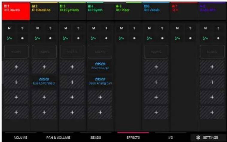
Use the M and S buttons to mute and solo the track. When Cue Tracks is enabled, the S button will become a Headphones button.
Use the automation button to set the Automation status of the track.
Use the record button to arm the track for recording.
Tap the Inserts button to open the Inserts window.
Use the four insert fields to add insert effects to the track. Empty insert slots will show a + icon. Inserts with a loaded effect will show the name of the effect.
To learn how to use insert effects, please see General Features > Effects > Insert Effects.
Swipe left while viewing the Effects tab to view the Return and Output Insert effects slots.
I/O
The I/O tab lets you view and edit audio and MIDI routing for your tracks.
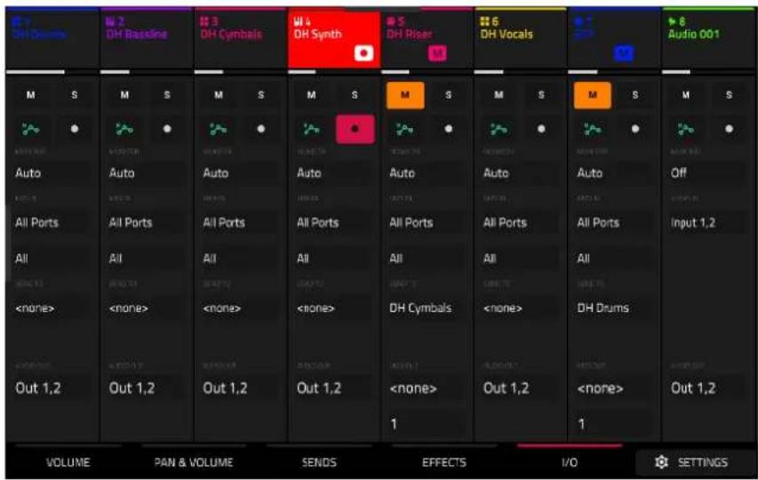
Use the M and S buttons to mute and solo the track. When Cue Tracks is enabled, the S button will become a Headphones button.
Use the automation button to set the Automation status of the track.
Use the record button to arm the track for recording.
Tap the Monitor button to set the monitoring behavior.
For Audio tracks:
Off: The track's audio input is not monitored.
In: The track's audio input is monitored whether the track is record-enabled or not.
Auto: The track's audio input is monitored while the track is record-enabled only.
For MIDI tracks:
Off: The track's MIDI input is not monitored, and playback of recorded events will be heard. This setting is useful when using keyboards with Local Control active.
In: The track's MIDI input is always monitored regardless of the track's Record Arm state, and playback from recorded events will not be heard.
Auto: The track's MIDI input is monitored when the track is record armed, and playback of recorded events will be heard.
Merge: The track's MIDI input is always monitored, and playback of recorded events will be heard.
Use the Input fields to select the input routing for the track.
For Audio tracks:
Use the Audio In field to configure the input source of the external audio signal, which you can set to a pair of inputs (Input 1,2) or a single input (Input 1, Input 2).
For MIDI tracks:
Use the MIDI Input and Channel fields to configure the MIDI input settings.
Use the Send To field to send the track's MIDI output to another track.
Use the Output field to set the output routing for the track.
For Audio tracks:
Use the Audio Out field to configure where the track is routed, which you can set to a submix (Sub 1–8), a pair of outputs (Out 1,2–Out 3,4), or a single output (Out 1–4).
For MIDI tracks:
Use the MIDI Output and Channel fields to configure the MIDI output settings.
Pad Mixer

In the Pad Mixer, you can set levels, stereo panning, and other settings for individual pads. This mode is only available for Drum and Keygroup tracks.
To open the Pad Mixer, do either of the following:
- Press Menu, and then tap Pad Mixer.
• Press and hold Shift and press Mixer.

bar
| Channel | Volume | PAN & VOLUME | SENS | EFFECTS | I/O | SETTINGS | |---|---|---|---|---|---|---| | A01 | -4.5dB | -9.3dB | -8.3dB | -3.4dB | -0.5dB | -7.1dB | | A02 | -4.5dB | -9.3dB | -8.3dB | -3.4dB | -0.5dB | -7.1dB | | A03 | -4.5dB | -9.3dB | -8.3dB | -3.4dB | -0.5dB | -7.1dB | | A04 | -4.5dB | -9.3dB | -8.3dB | -3.4dB | -0.5dB | -7.1dB | | A05 | -4.5dB | -9.3dB | -8.3dB | -3.4dB | -0.5dB | -7.1dB | | A06 | -4.5dB | -9.3dB | -8.3dB | -3.4dB | -0.5dB | -7.1dB | | A07 | -4.5dB | -9.3dB | -8.3dB | -3.4dB | -0.5dB | -7.1dB | | A08 | -4.5dB | -9.3dB | -8.3dB | -3.4dB | -0.5dB | -7.1dB |Just like the Channel Mixer, the Pad Mixer works like an audio mixer with various settings for each pad, with up to 8 pads shown on the display at once. The name of the pad is displayed at the top of each one.
To select a pad, tap it on your MPC hardware, or tap the channel strip header.
To view more pads, drag your finger left and right on the display.
Tap the Settings icon in the lower-right corner of the screen to open the Pad Mixer configuration to edit the following settings:
Check the Filter by events box to show only pads with events.
Check the Filter by samples box to show only pads with samples assigned.
Check the Write automation when recording box to set automation to always write when recording.
Volume
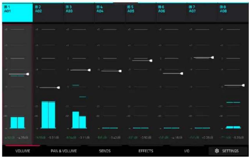
bar
| Category | Volume | PAN & VOLUME | SENS | EFFECTS | I/O | SETTINGS | |---|---|---|---|---|---|---| | A01 | -47.02 | -395.02 | -165.02 | -8.31 | -8.34 | -3.11 | | A02 | 0 | 0 | 0 | 0 | 0 | 0 | | A03 | 0 | 0 | 0 | 0 | 0 | 0 | | A04 | 0 | 0 | 0 | 0 | 0 | 0 | | A05 | 0 | 0 | 0 | 0 | 0 | 0 | | A06 | 0 | 0 | 0 | 0 | 0 | 0 | | A07 | 0 | 0 | 0 | 0 | 0 | 0 | | A08 | 0 | 0 | 0 | 0 | 0 | 0 | The chart displays a single bar for each category (A01 to A08) with corresponding values. The bars are colored cyan and white, indicating different data series or conditions. No numerical values are provided for the bars.The Volume tab gives you an overview of the volume level of your pads.
Tap and drag the level slider to adjust the volume level of the currently selected pad.
The level sliders and meters in each pad show a visual representation of the level. Double-tap a track on the screen to open a large version of the level slider and meter.
Pan & Volume

Use the M and S buttons to mute and solo the pad.
The pan sliders in each track show a visual representation of the pan. Tap and drag the pan slider to adjust the panning of the currently selected pad.
Tap and drag the level slider to adjust the volume of the currently selected pad.
Sends
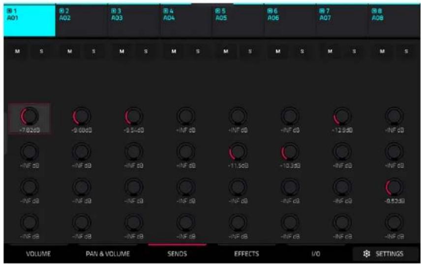
Use the M and S buttons to mute and solo the pad.
Use the send knobs to adjust the send level of the pads.
Important: When using send channels, make sure you have already loaded at least one effect to it using the return mixer.
Effects

Use the M and S buttons to mute and solo the pad.
Tap the Inserts button to open the Inserts window.
Use the four insert fields to add insert effects to the pad. Empty insert slots will show a + icon. Inserts with a loaded effect will show the name of the effect.
To learn how to use insert effects, please see General Features > Effects > Insert Effects.
I/O

Use the M and S buttons to mute and solo the pad.
Use the MIDI Out Enabled field to determine when a MIDI note is sent to the MIDI Output. This can be used for triggering external gear, lighting, or video systems. Select Never (no MIDI note is sent), Always (MIDI note is sent every time the pad is triggered), or When Empty (MIDI note is only sent if the pad has no internal sample).
Use the MIDI Out Note to select the specific MIDI note to send for the selected pad.
Use the MIDI Out Channel to select the MIDI Channel where the output is sent.
Use the Audio Out field to set the output routing for the pad. Select Track to output the pad to the track, or send it directly to one of the outputs.
Sounds Mode

Sounds Mode allows you to easily browse plugin instruments, save favorite presets, and build setlists to quickly recall projects for live performances.
To enter Sounds Mode, do either of the following:
- Press Menu, and then tap Sounds.
- Press the Sounds button (MPC Key 61, MPC Key 37).
When viewing either the Sounds or Favorites menu, you can swap to the other menu by tapping the first tab at the bottom of the touchscreen.

Tap the gear icon at the top of the screen to open the Sounds menu settings.
Use the Default View field to set Sounds mode to open viewing Instruments or the Current Preset by default.
Check the Loading instrument opens editor box to enable opening Track Edit Mode when loading an instrument.
Use the Audition fields to determine how samples are auditioned.
Tap Sync to enable or disable auditioning samples at the beginning of the next bar of the sequence when playback is active.
Tap Warp to enable or disable samples with an embedded tempo to be warped to the project tempo. Samples with no embedded tempo or externally-embedded tempo will not be affected by this setting.
Tap and drag the level slider up or down to set the audition volume level.

Tap Locate Preset at the top of the touchscreen to open the preset list for the currently selected plugin instrument.
Tap Edit Instrument at the bottom of the touchscreen to open Track Edit Mode to adjust the instrument parameters.
Tap Track -/+ at the bottom of the touchscreen to switch to another track.
Tap the ← Instruments button to select another track type to search for using the Sounds interface. You can search for Drum, Plugin, Keygroup, MIDI, CV, and Audio track types in any factory expansions or user expansions on any attached drives. When browsing an expansion or user folder, tap a cell to load the selected program.
When searching for non-Plugin tracks, you can also tap and hold on an empty space to set a preferred folder location for your saved tracks.
When viewing Drum and Keygroup track samples, tap the headphones icon to enable auditioning. Once enabled, tap and hold on a cell's play icon to audition the selected sound.
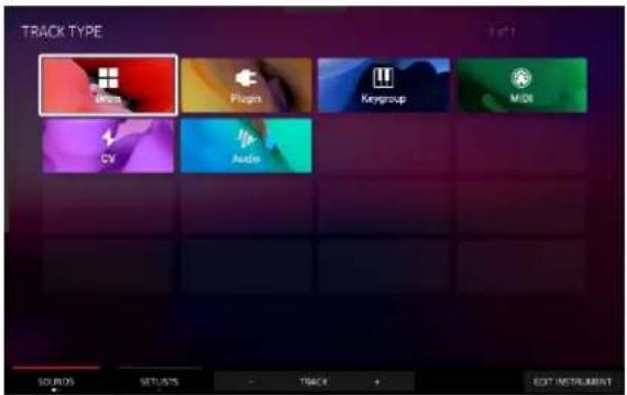
Favorites
When viewing the Sounds menu, tap the Sounds tab at the bottom of the screen to switch to the Favorites screen, where you can save, load, and organize your most-used presets. On MPC Key 61 and MPC Key 37, you can also press and hold Shift and press the Sounds button.
To save a preset as a favorite:
- Select the desired plugin and preset using the Sounds menu.
- Open the Favorites menu by tapping the bottom-left tab in the Sounds menu.
- Press and hold on an empty Favorites slot to save the preset in the selected slot.
To edit an existing Favorite slot, tap and hold on a filled Favorite slot. In the menu that appears:
- Tap Clear to clear the slot.
- Tap Overwrite to replace the favorite with the currently selected preset.

Setlists
Use the Setlists tab to create a list of projects to easily recall, such as for a live performance.
To create a Setlist:
- Open the Setlist tab from the Sounds page.
- Tap and hold on an empty Setlist slot, and then tap Choose Project.
- In the file browser that appears, locate the project you would like to add and then tap Select to load it.
To edit an existing Setlist slot, tap and hold on a filled slot. In the menu that appears:
- Tap Choose Project to select a different project for the same slot.
- Tap Clear to empty the selected slot.
- Tap Copy to copy the project to another slot. Then, tap and hold on an empty slot and tap Paste.

XYFX Mode
XYFX Mode turns the touchscreen into an XY pad where each axis represents the range of an effect parameter. As you move your finger on the XY pad, the current position will determine the current value of the two parameters. You can use this mode to create interesting effect automation on your tracks.
The effect you control in XYFX Mode acts like an insert effect on that track. In fact, XYFX is the name of the insert effect you have to load to the track before you can use this mode. Learn more about this in General Features > Effects.
To enter XYFX Mode, do either of the following:
- Press Menu, and then tap XYFX.
- Press XYFX (MPC X), Shift and Next Seq/XYFX (MPC Live II, MPC One), or Shift and Edit/XYFX (MPC Key 61, MPC Key 37).
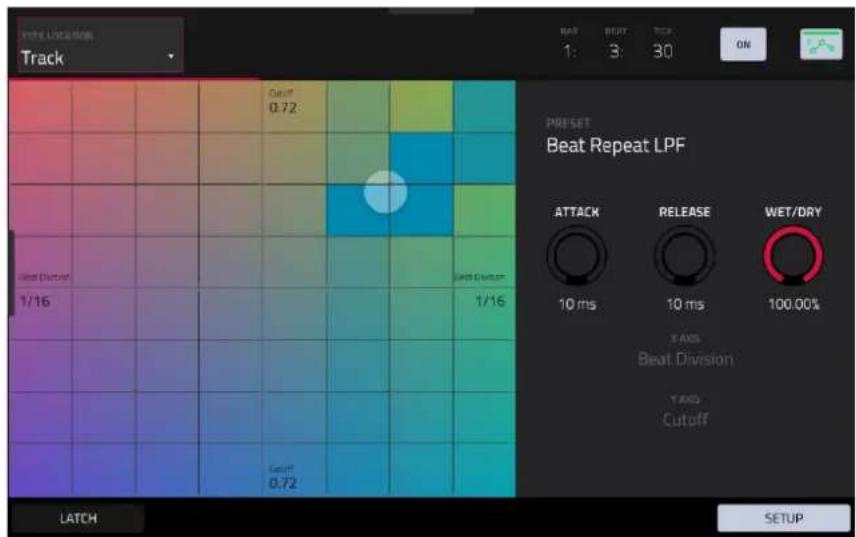
When you first enter this mode in a project, you may be prompted to load XYFX to the track. Tap Insert XYFX to do this.
Note: If you already have four insert effects loaded, you will need to clear one of the insert effect slots before doing this.
Use the XYFX Location field to select the signal to which the effects will be applied: the current track (Track) or a main output (a stereo pair of channels: Output 1/2 or Output 3/4).
Touch or move your finger on the gridded part of the screen. A marker will follow your finger to indicate the current position. The X axis is the horizontal axis, increasing in value as you move right. The Y axis is the vertical axis, increasing in value as you move up. Each axis is labeled with its assigned parameter.
When an effect has a beat division parameter, the current division will be highlighted as an entire column.
Effects are differently colored for easy visual distinction: beat-synchronized effects are blue, while manually controlled effects are green.

XY Mode with a beat-synchronized effect.
While touching the XY pad, tap Latch in the lower-left corner to keep the marker on the XY pad even after you release it. The marker will remain there until you touch another part of the XY pad or until you tap Latch again.
Use the Setup button to show or hide the Setup panel, which controls how the XY pad behaves.
Use the Preset field to select the effect you want to use in XYFX Mode.
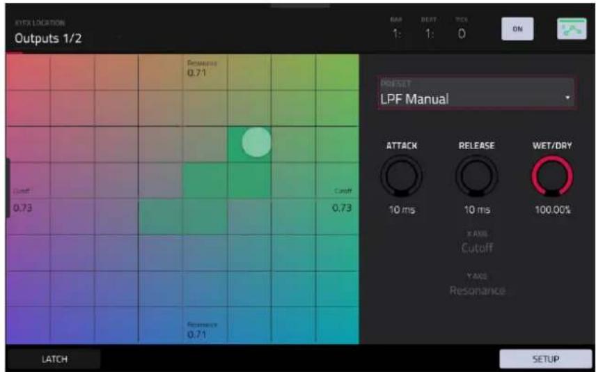
XY Mode with a manually controlled effect.
Use the Attack knob to set the length of the attack phase of the envelope, which is triggered when you touch the XY pad. In other words, this determines how long it takes the effect to fully respond to your touch.
Use the Release knob to set the length of the release phase of the envelope, which is triggered when you release the XY pad. In other words, this determines how long it takes the effect to fully deactivate after you stop touching the XY pad.
Use the Wet/Dry knob to set the blend the original signal (dry) and the effect signal (wet).
The X Axis and Y Axis fields show which parameters are controlled by each axis. This varies depending on the effect you are using.
Arrange Mode
Arrange Mode is a fully-featured linear sequencer where you can record a performance or live input (MIDI or audio) into a linear timeline to create an arrangement of a song. You can use the powerful Arrange Edit commands to edit and arrange your song and then mix it down to a stereo audio file, or stem it as separate tracks.
To enter Arrange Mode, do either of the following:
- Press Menu and then tap Arrange.
The event editor's Arrange, Grid, and List views are displayed as tabs in the top left of the screen to make it easy to jump between them.


The toolbar at the top of Arrange Mode lets you switch between the different edit modes as well as showing project and timing information.
Use the Arrange, Grid, and List icons to switch between the different modes.
Tap the automation icon to toggle between Read and Write. To disable or enable global automation entirely, press and hold Shift and tap this icon.
Use the BPM field to adjust the tempo of the project.
Use the Bars field to set the length of the arrangement.
The time counter at the top of the screen indicates the current playhead position. Double-tap this field to open the Locate Window.
Tap the pencil Edit icon to open the Sequence Edit window (see Editing Arrangements).
Tap the gear icon to open the Grid Settings.
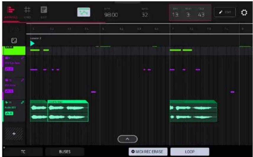
The project's tracks are displayed in Arrange Mode on a linear timeline.
Tap a track to select it.
You can also press and hold Main and a window will appear showing all tracks in your project in a four-by-four layout, mirroring your MPC pads. Tap a track in the window to select, or press the respective pad on your hardware.
From this window, you can also tap Tracks, Submixes, Returns, and Outputs to display the selected track types in the window.
Each track header will show Record Arm, Mute, Solo, and Track Automation states. Note that this requires the vertical zoom to be adjusted so there is enough space to show all components. Use the pinch and expand gestures to change the zoom level of the arrangement.
Tap TC at the bottom of the screen to open the Timing Correct (TC) window. Alternatively, tap the timing correct value shown above the track headers.
Tap Buses to view Submix, Return, and Output bus tracks. You can then record, edit, and view automation data on these tracks in your Arrangement the same way you can with other tracks.
Tap the MIDI Rec Erase button to enable or disable MIDI record erasing in Arrange Mode. When enabled, the new recording will replace existing MIDI data in the arrangement. When disabled, recording MIDI will overdub on existing MIDI data in the track arrangement.
Tap Loop to enable or disable loop. The loop region is always displayed, regardless of whether Loop is on or off.
The Arrangement timeline also features six user-controllable Locate markers. Press and hold Shift to show the six Locator buttons at the bottom of the screen.
To add a locator at the playhead position, tap one of the six Locator buttons. You can also use the Locate window to edit these markers.
Recording Arrangements
To record into the arrangement timeline:
- In Main Mode, tap the Rec Arm function button to arm the selected track for recording. Alternatively, double-tap the track header in Arrange Mode and then set the Rec Arm field to On.
- Press the Rec button on your hardware to arm it for recording.
- Next, enter Arrange mode by pressing Menu and tapping Arrange. You can also view the arrangement directly from Main Mode by opening the Arrangement header.
- Press Play on your hardware to begin recording. As you record, Arrange Mode will draw regions containing audio or MIDI data into the track lanes.
To replace a section of the arrangement with a new performance:
- Tap the Loop button at the bottom of the screen to activate loop.
- Set the Loop Start and Loop End points by tapping and dragging the beginning and end of the loop region in the timeline. Tapping and dragging in the middle of the loop region moves both the Loop Start and Loop End points at the same time.
- Enable arrangement recording by following the directions above.
- Press Play to begin recording. The recording will begin at the Loop Start point, and once it reaches the Loop End Point, will switch to Overdubbing mode.
You can also use the Auto Record and Punch In/Punch Out functions of the Arrangement Section of Main Mode to easily replace part of a recording.
To play the arrangement:
- Press Play Start to begin playback of the arrangement from 1:1:00, or if Loop is activated, from the Loop Start.
- Press Play to begin playback from the current playhead position.
To move the playhead position, tap the Playhead Position field in the toolbar to select it, and then use the data dial or -/+ buttons to adjust the value. Alternatively, you can set the playhead position by tapping in the lower-half of the timeline.
Editing Arrangements
You can edit your linear arrangement using MPC's powerful Sequence Edit commands.
To edit an arrangement, tap the pencil icon in the Arrange Mode toolbar to open the Sequence Edit window, and then select one of the following tools.
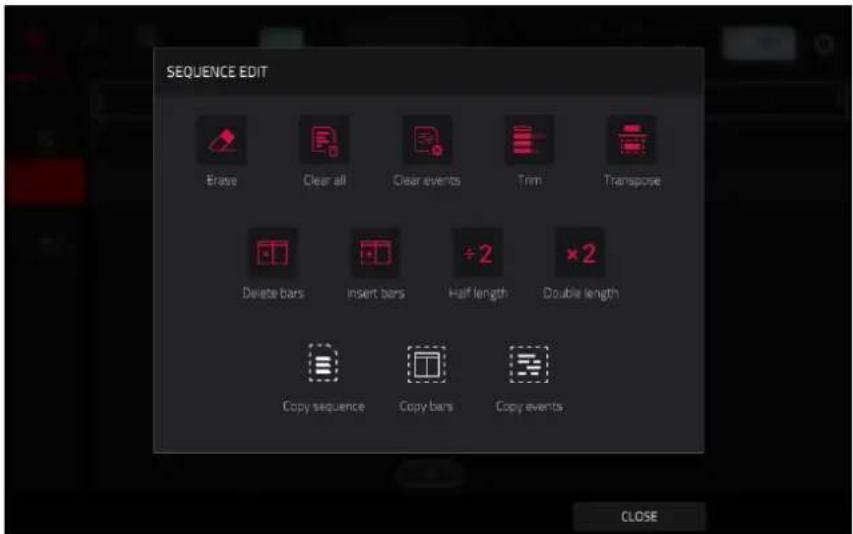
The Erase function erases all or part of the sequence.
Use the Track field to select the track you want to erase within the sequence.
Use the Bar, Beat, and Tick fields to set the time range of the sequence you want to erase. The left fields set the start of the time range, and the right fields set the end of the time range.
To select what types of events you erase, select one of the Erase options:
All erases all pad events from the designated time range and reset all of its settings.
Automation erases only automation from the designated time range. Use the Parameter field to select what type of automation is erased.
Note erases notes from the selected pads in the designated time range. Use your MPC hardware pads to select or deselect pads.
Except Note erases all notes except those selected in the designated time range. Use your MPC hardware pads to select or deselect pads to be exempted from deletion.
Tap Do It to confirm your choice, or tap the X, Cancel, or anywhere outside the window to cancel and return to the previous screen.


The Clear All function erases all events from the sequence and resets all of its settings.
Tap Clear All to confirm your choice.
Tap Cancel to return to the previous screen.
The Clear Events function only erases all events from the sequence.
Tap Clear Events to confirm your choice.
Tap Cancel to return to the previous screen.
The Trim function immediately crops the arrangement to the Bars value in the main Arrangement Mode window.
The Transpose function transposes a range of events on a track in an arrangement. The events within that range will shift accordingly in the Grid View. This option is available for MIDI tracks only.
Use the Track field to select the track you want to transpose within the arrangement.
Use the two sets of Bar, Beat, and Tick fields to set the time range of the arrangement you want to transpose. The left fields set the start of the time range, and the right fields set the end of the time range.
For drum tracks, use the two Pad fields to select the "source" pad (whose events you want to move) and "destination" pad (where the events will be placed). Tap each field and then press the desired pad.
For keygroup tracks, plugin tracks, and MIDI tracks, set the range and amount of transposition:
Range: Use the two Note fields to set the range of notes of the events you want to transpose. Note events within this range will be transposed, while note events outside of this range will remain unchanged.
Transpose: Use this field to set how many semitones up or down you want to transpose the note events.
Tap Do It to confirm your choice, or tap the X, Cancel, or anywhere outside the window to cancel and return to the previous screen.

The Delete Bars function removes a range of bars from the arrangement.
Use the First Bar and Last Bar fields to set the range of bars to delete from the arrangement.
To confirm your choice, tap Do It.
Tap Do It to confirm your choice, or tap the X, Cancel, or anywhere outside the window to cancel and return to the previous screen.
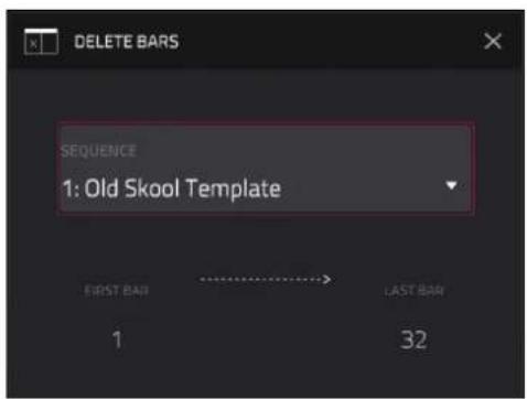
The Insert Bars function adds a number of bars to the arrangement.
Use the # of bars field to set how many bars to add.
Use the Before Bar field to set where the bars are added. The bars will be inserted before this bar.
Tap Do It to confirm your choice, or tap the X, Cancel, or anywhere outside the window to cancel and return to the previous screen.

The Half Length function immediately halves the length of the arrangement.
The Double Length function immediately doubles the length of the arrangement.
The Copy Sequence function copies the contents of one sequence to another.
Use the Copy Contents of Sequence field to select the "source" sequence. This is the sequence whose events you want to copy.
Use the Over Contents of Sequence field to select the “destination” sequence. This is the sequence where the source sequence will be copied.
Tap Do It to confirm your choice.
Tap Cancel to cancel and return to Arrange Mode.

The Copy Bars function copies a range of bars from the arrangement and adds them at a specified point.
Use the First Bar and Last Bar fields to set the range of bars to copy from the arrangement.
Use the After Bar field. The copied bars will be inserted after this one to set where you want to add the copied bars.
Use the Copies field to set how many instances of the copied bars you want to add.
Tap Replace to overwrite the arrangement at the destination.
Tap Merge to add the events to the destination without erasing anything.
Tap Cancel to cancel and return to Arrange Mode.
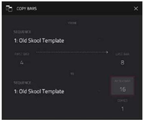
The Copy Events function copies a range of events from a track in the arrangement and adds them to another at a specified point.
Use the From Track field to select the "source" track. This is the track whose content you want to copy.
Use the field below the From Track field to set what content is copied. Copy All Events will copy and paste all events in the track. Copy Only Selected Events will copy and paste only the events that are currently selected.
Use the Bar, Beat, and Tick fields to set the time range of the events or the audio track you want to copy. The left fields set the start of the time range, and the right fields set the end of the time range.
Use the To Track field to select the "destination" track. This is the track where the content of the source track will be copied.
Use the Bar, Beat, and Tick fields to set where you want to add the copied events or audio track. The events or audio track will be added after this point.
Use the Copies field to set how many instances of the copied events or audio track you want to add.
Tap Replace to overwrite the arrangement at the destination.
Tap Merge to add the events to the arrangement at the destination without erasing anything.
Tap Cancel to cancel and return to Arrange Mode.
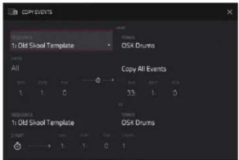

In Arrange Mode, you can tap and hold on the header for a MIDI track (on the left side of the screen) to open a drop-down menu of track edit options for MIDI tracks.
The Clear function erases all events from the track.
Tap Clear to confirm your choice.
Tap Cancel to return to the previous screen.
The Delete Track function instantly removes the track and all of its contents.
The Duplicate Track function immediately duplicates the selected track to a new track.
The Copy Events function copies a range of events from a MIDI track in the arrangement and adds them to another at a specified point.
Use the From Track field to select the "source" track. This is the track whose content you want to copy.
Use the field below the From Track field to set what content is copied. Copy All Events will copy and paste all events in the track. Copy Only Selected Events will copy and paste only the events that are currently selected.
Use the Bar, Beat, and Tick fields to set the time range of the events or the audio track you want to copy. The left fields set the start of the time range, and the right fields set the end of the time range.
Use the To Track field to select the "destination" track. This is the track where the content of the source track will be copied.
Use the Bar, Beat, and Tick fields to set where you want to add the copied events or audio track. The events or audio track will be added after this point.
Use the Copies field to set how many instances of the copied events or audio track you want to add.
Tap Replace to overwrite the arrangement at the destination.
Tap Merge to add the events to the arrangement at the destination without erasing anything.
Tap Cancel to cancel and return to Arrange Mode.

The Double-Speed Events function immediately halves the lengths of all note events on the track in the arrangement as well as the distance between them. In other words, the track's notes are pressed closer together so the track sounds like it is playing at twice the previous speed. This does not actually affect the pitches of notes or the tempo.
The Half-Speed Events function immediately doubles the lengths of all note events on the track in the arrangement as well as the distance between them. In other words, the track's notes are spread further apart so the track sounds like it is playing at half of the previous speed. This does not actually affect the pitches of notes or the tempo.
The Pitch Quantize function forces the pitches of note events into a specific scale.
Use the Root Note field to select the desired root note of the scale.
Use the Scale field to select a type of scale.
To determine which note events will be quantized, tap the Only apply to selected events checkbox.
When on, only the currently selected note events will be quantized.
When off, all pitches in the current track will be quantized.
Use the Start Note and End Note fields to set lowest-possible and highest-possible pitches where the quantized note events will be placed (respectively). If a note event is originally outside of this range, it will be forced to the nearest pitch (within the scale) inside the range.
Tap Do It to confirm your choice, or tap the X, Cancel, or anywhere outside the window to cancel and return to the previous screen.
![PATCH QUARTIZE Setup Rout Amount C SCALE Major Note Input Filter [ ] Only apply to selected events Output Note Range Quantized notes will be moved up/down by an octave to fit into this note range. START NOISE F=2 ENSMOSIS GB](/content/2026/05/883354/images/6f0cdb5d1cd4603337c0548db34bd36435b532d9cae7a60cb083c7e5fe0ca2bc.jpg)
The Bounce to Sample function immediately renders the track as an audio sample and places it in the project's sample pool. By default, it will be named Bounce - and appended with the track name. This function does not work for MIDI or CV tracks.
The Bounce to Audio Track function immediately renders the track as an audio track in the project. By default, it will be named Audio and appended with a number (e.g., Audio 002). This function does not work for MIDI or CV tracks.

You can also tap and hold on the header for an audio track (on the left side of the screen) to open a drop-down menu of track edit options for audio tracks.
The Clear function erases all events from the track and resets all of its settings.
To confirm your choice, tap Clear.
To return to the previous screen, tap Cancel.
The Delete Track function instantly removes the track and all of its contents.
The Duplicate Track function immediately duplicates the selected track to a new track.
The Copy Events function copies selected audio track regions from the track and adds them to another at a specified point.
Use the From Track field to select the "source" track. This is the track whose content you want to copy.
Use the field below the From Track field to set what content is copied. Copy All Events will copy and paste all events in the track. Copy Only Selected Events will copy and paste only the events that are currently selected.
Use the Bar, Beat, and Tick fields to set the time range of the events or the audio track you want to copy. The left fields set the start of the time range, and the right fields set the end of the time range.
Use the To Track field to select the "destination" track. This is the track where the content of the source track will be copied.
Use the Bar, Beat, and Tick fields to set where you want to add the copied events or audio track. The events or audio track will be added after this point.
Use the Copies field to set how many instances of the copied events or audio track you want to add.
Tap Replace to overwrite the arrangement at the destination.
Tap Merge to add the events to the arrangement at the destination without erasing anything.
Tap Cancel to cancel and return to Arrange Mode.

The Reset Channel Strip function immediately:
• clears all Insert effect slots;
• turns Mute, Solo, automation, and Monitor off;
• resets the pan knob to the center;
• resets the level slider to 0.00 dB; and
• turns the Record Arm button off.
The Bounce to Sample function immediately renders the track as an audio sample and places it in the project's sample pool. By default, it will be named Bounce - and appended with the track name.
The Flatten Track function renders all edits and regions within the current track's arrangement to a new audio file.
The Flatten Track Elastique function also renders all edits and regions within the current track's arrangement to a new audio file, but renders any time-stretching or pitch-shifting using the Elastique Pro algorithm, providing higher-quality results with less artifacts than MPC's standard algorithm.
Arrangement Track Editor
When in Arrange Mode, events from the currently selected track can be edited using the bottom panel track editor.
To open the track editor, do either of the following:
- Tap the arrow up icon at the bottom of the screen.
- Double-tap inside a track lane in the main arrangement view.

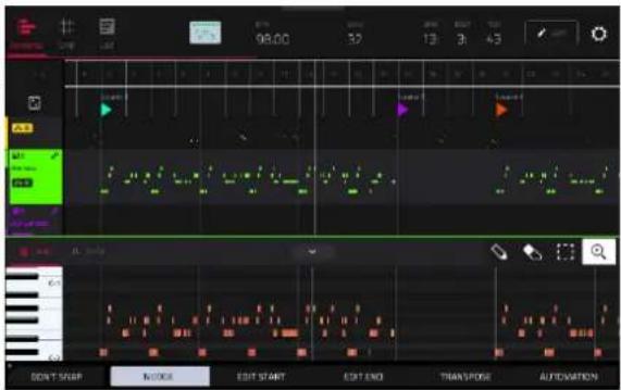
Once opened, you can also adjust the height of the track editor by tapping and dragging the arrow icon or anywhere in the editor toolbar.
For drum tracks, you can tap and hold on a pad header in the track editor to open a drop-down menu where you can quickly Mute, Solo, or change the Color of the pad.
To close the track editor, tap the down arrow icon.
At the top of the Track Editor are two tabs, Grid and Auto. Use the Grid tab to edit MIDI events or audio regions. Use the Auto tab to edit automation for the track. The editing workflow in the arrangement track editor is the same as in the Grid View.
Press and hold Shift to view additional editing options for the Track Editor.
Tap Select All to select all events.
Tap Cut to cut the selected events.
Tap Copy to copy the selected events.
Tap Paste to paste the selected events at the playhead location.
Tap Delete to delete the selected events.
Tap Duplicate to duplicate the selected events. The events will be added after the last selected event.

Saving and Exporting the Arrangement


To save and export your arrangement, press the Menu button, and then tap Save. In the Save window, select Audio Mixdown to mixdown or stem your arrangement into individual files.
Use the Start Bar and End Bar fields under Audio Length to set the time range that you want to mixdown. You can add a number of seconds to the end of the mixdown to capture any ringing notes or effects (such as a reverb tail) by adjusting the Audio Tail field.
Use the fields under Render Source and Render Options to set the parameters for the audio mixdown. Check the Separate Tracks box to render each track of the arrangement as stems.
To configure the audio mixdown file settings, use the fields at the bottom of the screen to set the File Format, Bit Depth, and Sample Rate.
You can also export the arrangement as an ALS file to use with Ableton Live.
To export the arrangement for Ableton, press the Menu button and then tap Save. In the Save window, select Ableton Live Set to bring up the Ableton Live Set Export popup.
Use the Export MIDI As settings to choose how MIDI tracks are exported, either as Audio files or MIDI files. When using Plugin, Drum, or Keygroup tracks, you can render the arrangement as Audio to preserve the sound of the instruments, or render the arrangement as MIDI data.
Check the Include Track Volume/Pan Settings box to include these settings in the export. When disabled, the volume and pan settings will be set to 0 dB and center (C), respectively.
Check the Bypass Track Effects Plugins box to deactivate any third-party effect plugins used with the track for the export. When disabled, those effects will be activated.
Use the Audio Tail field to set the amount, in seconds, of extra time added to the end of the resulting audio files.
Use the Bit Depth field to set the bit depth to 8, 16 or 24.
Use the Sample Rate field to set the sample rate to 44.1, 48, 88.2 or 96 kHz. In most cases, we recommend selecting 44.1 kHz.
Grid View
The Grid View lets you view and edit the note events or audio regions of each track in a project and their velocities. This mode has three different appearances: one for audio tracks, one for drum tracks and one for keygroup tracks, MIDI tracks, and plugin tracks.
To enter Grid View, do any of the following:
- Press Menu and then tap Grid. You can also tap Grid at the top of the screen in Arrange Mode or List Mode.
For audio tracks, the waveform of the audio sample is shown.
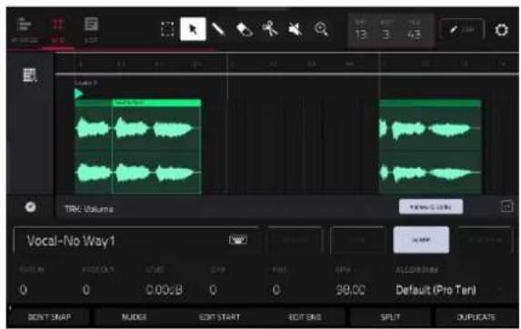
For drum tracks, the left column shows you all available pads in a vertical view with their corresponding events in the grid to the right.
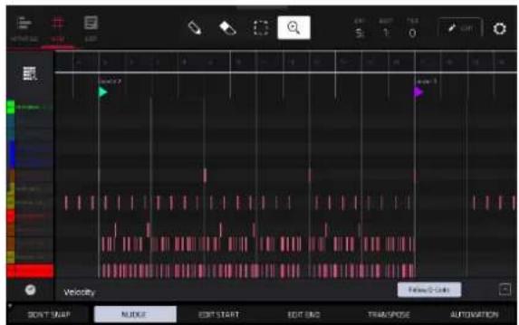
For keygroup, plugin, MIDI and CV tracks, the left column shows a vertical "piano roll" keyboard with the corresponding events in the grid to the right.


In all views, the time counter at the top of the screen indicates the current playhead position.
Tap the gear icon to open the Grid Settings window to configure the following Grid Editor settings:
Use the Snap Mode selector to set how events "snap" to the grid.
Absolute: Events will "snap" to the nearest time division on the grid (as determined by the TC field or Timing Correct window). This is the typical and traditional method of using the snap/quantization feature.
Relative: Events will "snap" to the nearest time division on the grid (as determined by the TC field or Timing Correct window) plus the original time position of the event (e.g., an event that is originally three ticks past a time division on the grid will snap only to positions that are three ticks past every time division).
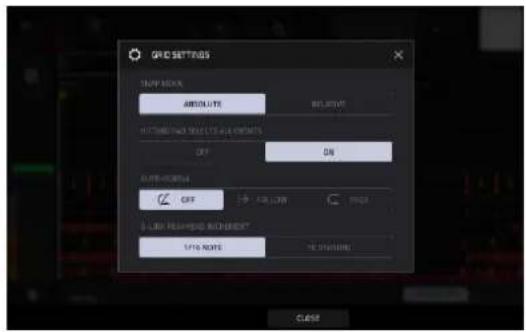
Use the Hitting Pad Selects All Events selector to turn the feature on or off. When On, pressing a pad will automatically select all note events for that pad on that track. When set to Off, pressing a pad will simply play its sound without selecting any note events.
This setting is not available when using audio tracks.
Use the Auto-Scroll selector to set how the screen behaves relative to the audio playhead.
Follow: The list will scroll along in the background while keeping the audio playhead centered.
Page: The list will move to the "next page" to follow the audio playhead.
Off: The list will not move at all.
Use the Q-Link Playhead Increment selector to set how much the playhead moves by when using the Q-Link controls. Select 1/16 Note to lock playhead movement to 1/16 notes, or select TC Division to have the playhead movement tied to the current Timing Correct division. This value can be set in the Timing Correct window in Grid View by tapping the clock icon at the bottom-left of the grid.
These functions also apply to Arrange Mode.
Audio Tracks
When viewing audio samples in Grid View, these seven tool icons at the top of the screen enable you to use different functions in the sample.

natural_image
Pure toolbar icons including cursor, pencil, eraser, scissors, folder, and play button (no text or symbols)Tap one to select its mode:

Marquee: Marquee Mode:
To select a sample region, tap the upper third of it.
To move a sample region (or multiple selected sample regions), tap and drag the upper third of it left or right.
To split the sample at two specific points (creating a sample region on either side and between them), tap and drag across the middle third of it to create a translucent white box, and then tap the upper third of that box.
To shorten or lengthen a sample region (or multiple selected sample regions), tap and drag the lower third of it left or right.

Arrow: Selection Mode:
To select a sample region, tap it.
To move a sample region (or multiple selected sample regions), tap and drag the upper third of it left or right.
To shorten or lengthen a sample region (or multiple selected sample regions), tap and drag the lower third of it left or right.
Pencil: Draw Mode:
To draw automation, open the velocity/automation lane and tap and drag.

Eraser: Erase Mode:
To erase a sample region (or multiple selected sample regions), tap it.

Scissors: Split Mode:
To split the sample at a specific point (creating a sample region on either side), tap that point in the sample.
To select a sample region, tap its left-most edge.

Mute: Mute Mode:
To mute or unmute a sample region (or multiple selected sample regions), tap it.

Magnifying Glass: Navigation Mode:
To move to another part of the sample, tap and drag it.
To zoom in or out, spread or pinch your fingers (respectively) on the grid. You can do this vertically, horizontally, or both at the same time.
Tap the pencil Edit icon to open the Grid Edit menu for audio regions:
Use Clear to clear audio from the track.
Use Double Length with Events to double the length of the track, including doubling the audio samples.
Use Flatten or Flatten Elastique to flatten the audio track when transport playback is stopped, rendering all the edits and regions within the arrangement to a single new audio file. The Elastique Pro algorithm can be used for time-stretching or pitch-shifting, providing higher-quality results with less artifacts than MPC's standard algorithm.
Use Bounce to Sample or Bounce to Audio Track to export the audio regions to a new sample added to the project sample pool or a new audio track in the project.
Use the Audio Tail field to set the amount, in seconds, of extra time added to the end of the resulting audio files.
Regardless of which tool is selected, you can do any of the following to edit the selected audio regions.
To select an audio region, tap the arrow icon to enter Selection Mode and tap an audio region. When an audio region is selected, all region parameters will be available to edit.
Press Undo on your MPC to undo your last action.
Press Shift and Undo on your MPC to redo the last action you undid.
To move the selected audio region, tap Nudge at the bottom of the screen, and then use the data dial or - / + buttons to shift the audio region left or right. Alternatively, if the arrow tool or marquee tool are selected, tap and drag the upper third of the selected audio region left or right. By default, you can move an audio region only by quantization values defined by the Timing Correct (TC) value.
To move the selected audio region without restricting (“snapping”) it to the quantization grid, tap Don’t Snap in the lower-left corner of the screen, and then use the data dial or -/+ buttons to shift the audio region. In this case, each nudge is equivalent to four ticks.
To adjust the start point or end point of the selected audio region (without changing its position), tap Edit Start at the bottom of the screen, and then use the data dial or - / + buttons.
Tap Split at the bottom of the screen to split the audio region at the current playhead position (creating an audio region on either side).
To copy, cut, or paste the selected audio region, press and hold Shift, and then tap Copy or Cut. Turn the data dial to move the highlighted audio region, and then press the data dial to paste it at its current location. Alternatively, press and hold Shift, and then tap Paste (respectively).
Tap Duplicate at the bottom of the screen to duplicate the selected audio region. The duplicate audio region will appear immediately after the original one.
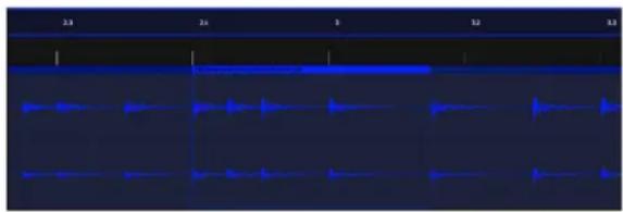
Use the Fade In or Fade Out fields to create a fade-in or fade out for the selected audio region, respectively. The fades will be shown as a sloped line at the start or end of the audio region.
Use the Level field to set the level of the selected audio region. The waveform amplitude will change accordingly.
Tap Reverse to reverse the selected sample region.

natural_image
Pure electrical circuit lines without any symbolsTap Mute to mute the selected sample region.

To lengthen or shorten the selected audio region without changing its pitch, tap Warp, which will enable the Semi, Fine, and BPM fields next to it.
Use the BPM field to change the tempo manually, which will change the length of the audio region accordingly.
To have MPC analyze the tempo of the region, tap the Detect BPM button. In the Edit BPM window that appears, you can do any of the following:
• Use the BPM field to enter a tempo manually. This is the same as the BPM field on the previous page.
- Tap Detect to detect the tempo automatically.
- Tap Tap Tempo at the bottom of the screen at the desired rate to use it as the tempo.
- Tap Close, the X, or anywhere outside the window to close it.
Use the Semi and Fine fields if you want to change the pitch (this is useful for matching the durations of two samples with different pitches).
Use the Algorithm field to set the Warp algorithm for the sample. By default, this will be set to whatever is selected as the Default Audio Warp Algorithm under Menu > Preferences > Audio/Export. Adjusting the setting here will override the default selection. Select Pro Ten or Repitch. When using Repitch, warping an audio sample will adjust its pitch to synchronize it with the MPC tempo.
Tip: You can configure audio track recording to ensure the resulting audio region is warped automatically. You can then adjust the project tempo while audio region remains in time. See Menu > Preferences > General to learn about this.
Note: When you record an audio file, the current project tempo will be embedded with it. This information is stored within the sample file when you save the project. When you warp an audio region, the warping algorithm uses this project tempo and the current value in the BPM field to generate the “stretch factor.”
Note: Warp algorithms are very CPU-intensive and can result in audio drop-outs during playback if used too freely. Be mindful of how (and how often) you use the warp function. You can reduce the CPU resources required by doing any/all of the following:
Minimize the amount of pitch adjustment (e.g., the Semi and Fine fields).
Avoid warping very small audio regions.
Warp as few tracks or audio regions as possible (i.e., reduce the number of total number of voices [of the polyphonic limit] that use the warp algorithm at a given time), especially instances where the warped regions start at the same time.
If you have warped samples used in a drum kit, consider using the Flatten Pad function to consolidate the affected pad's layers into one audio sample. After you flatten the pad, its sample/samples no longer need to be warped.
To open the Timing Correct (TC) window, press and hold Shift, and then tap TC at the bottom of the screen. Alternatively, tap the clock icon next to the automation lane.
To clear all automation from the track, press and hold Shift, and then tap Clear Auto.
To solo the track, press and hold Shift, and then tap Solo at the bottom of the screen.
MIDI Tracks
When viewing MIDI tracks in Grid View, use these four tool icons at the top of the screen to use different functions in the grid.

natural_image
Four white icons on a black background: pencil, eraser, square, and play button (no text or symbols)Tap one to select its mode:
Pencil: Draw Mode:
To enter a note in an empty grid square, tap the grid square.
To select a note, tap it.
To move a note, tap and drag it to another grid square.
To erase a note, double-tap it.
To edit velocity or draw automation, tap and drag in the velocity/automation lane.
Eraser: Erase Mode:
To erase a note, tap it. You can also tap and drag to erase multiple notes in the same row.
Select Box: Select Mode:
Note: Notes will remain selected if you switch to another mode. The selection will change, however, if you press a pad while Hitting Pad Selects All Events is set to On.
To select a note, tap it.
To select multiple notes, tap and drag across the grid to create a box around them.
To move a note, tap and drag it to another grid square.
To move multiple notes, select them as described above, and tap and drag them.
To erase multiple notes, select them as described above, and then select the eraser tool and tap any of the selected notes.
Magnifying Glass: Navigation Mode:
To move to another part of the grid, tap and drag it.
To zoom in or out, spread or pinch your fingers (respectively) on the grid. You can do this vertically, horizontally, or both at the same time.
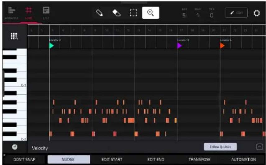
Regardless of which tool is selected, you can do any of the following to move, lengthen, shorten, or transpose any selected note/notes.
Tap the grid-and-magnifying-glass icon in the lower-left corner to automatically set the grid to view the active area, up to three pad banks and 32 bars.
Press Undo on your MPC to undo your last action.
Press Shift and Undo on your MPC to redo the last action you undid.
Press the desired pad to select all notes for a pad.
To move the selected notes, tap Nudge at the bottom of the screen, and then use the data dial or - / + buttons to shift the notes left or right. By default, you can position notes only by quantization values defined by the Time Correct value.
To move the selected notes without restricting ("snapping") them to the quantization grid, tap Don't Snap in the lower-left corner of the screen, and then use the data dial or - / + buttons to shift the notes. In this case, each nudge is equivalent to four ticks.
To adjust the start point or end point of the selected notes (without changing their position), tap Edit Start or Edit End at the bottom of the screen, and then use the data dial or - / + buttons.
To transpose the selected notes up or down, tap Transpose at the bottom of the screen, and then use the data dial or - / + buttons.
To adjust an automation parameter for the selected notes, tap Automation at the bottom of the screen, and then use the data dial or - / + buttons to adjust the selected automation parameters.
To select all notes in the grid instantly, press and hold Shift and then tap Select All at the bottom of the screen.
To copy, cut, or paste the selected notes, press and hold Shift, and then tap Copy or Cut. Once the notes have been copied or cut, press and hold Shift, and then tap Paste to add them to the current playhead position.
To delete the selected notes, press and hold Shift and then tap Delete at the bottom of the screen.
To duplicate the selected notes instantly, press and hold Shift and then tap Duplicate at the bottom of the screen. The duplicate notes will appear immediately after the original ones.
To open the Timing Correct (TC) window, press and hold Shift and then tap TC at the bottom of the screen. Alternatively, tap the clock icon next to the automation lane.
Tap the pencil Edit icon next to the time counter to open the event editing window. You can use any of these functions as described below.
To return to Grid View, tap Cancel or tap at the top of the screen.
The Clear Events function erases all events from the track.
Tap Clear to confirm your choice, or tap Cancel to return to the previous screen.
The Double Length with Events function immediately doubles the length of the arrangement and duplicates the events.
The Half-Speed Events function immediately doubles the lengths of all note events in the sequence as well as the distance between them. In other words, all notes are spread further apart so the sequence sounds like it is playing at half of the previous speed. This does not actually affect the pitches of notes or the tempo.
The Double-Speed Events function immediately halves the lengths of all note events in the sequence as well as the distance between them. In other words, all notes are pressed closer together so the sequence sounds like it is playing at twice the previous speed. This does not actually affect the pitches of notes or the tempo.
The Pitch Quantize function forces the pitches of note events into a specific scale.
Use the Root Note field to select the desired root note of the scale.
Use the Scale field to select a type of scale.
To determine which note events will be quantized, tap the Only apply to selected events checkbox.
When on, only the currently selected note events will be quantized.
When off, all pitches in the current sequence will be quantized.
Use the Start Note and End Note fields to set lowest-possible and highest-possible pitches where the quantized note events will be placed (respectively). If a note event is originally outside of this range, it will be forced to the nearest pitch (within the scale) inside the range.
Tap Do It to continue and quantize the note events, or tap Close, the X, or anywhere outside the window to cancel.

The Humanize function applies randomization to the timing, length, and/or velocity of note events.
Tap the Humanize Time checkbox to select whether or not humanization will be applied to the timing of note events.
Use the Amount (Pulses) slider to select the maximum number of pulses by which the timing of an event will be adjusted.
Use the Eagerness slider to set how dramatically the humanization effect is applied to the timing. Negative values correspond to playing “ahead of the beat” while positive values correspond to playing “behind the beat.”
Tap the Humanize Note Length checkbox to set whether or not humanization will be applied to the duration of note events.
Use the Length (%) slider to set how dramatically the humanization effect is applied to note lengths.
Tap the Humanize Velocity checkbox to set whether or not humanization will be applied to the velocities of note events.
Use the Strength (%) slider to set how dramatically the humanization effect is applied to note velocities.
Tap the Only Apply to Selected Events checkbox to determine which notes will use these humanization values:
When on, just the currently selected notes will be humanized.
When off, all notes in the sequence will be humanized.
Tap Apply to apply humanization and keep this window open.
Tap Do It to apply humanization and close the window.
Tap Close, the X, or anywhere outside the window to close the window without making any changes.


The Generate Random Events function creates random melodic or drum patterns in the current sequence.
Use the Event Type field to select Drum Events or Melodic Events to select the type of events you want to create.
Use the Replace field to select how the events will be created relative to the existing events on the track:
Replace All Events: Select this option to replace all events in the sequence with the randomly generated ones.
Replace Events in Note Range: Select this option to replace all events in the designated note range in the sequence with the randomly generated ones. Use the Bank or Start Pad and End Pad menus to set the note range for drum events or the Start Note and End Note menus to set the note range for melodic events.
Add to Existing Events: Select this option to add the randomly generated events to the sequence without replacing or overwriting the existing ones.
Use the Pattern Size (Bars) field to set how many bars the events will use. The highest possible value is the number of bars in the current sequence.
Use the Note Length field to select the duration of the events. (This feature is nonfunctional if Legato is enabled while generating melodic events.)
Tap Apply to generate the events and keep this window open.
Tap Do It to generate the events and close the window.
Tap Close, the X, or anywhere outside the window to close the window without generating any events.
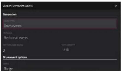
If Event Type is set to Drum Events:
Use the Bank field to select the pad bank that will be used to generate the events, or select Range to use the Start Pad and End Pad menus to define a specific pad range instead.
Use the Start Pad or End Pad fields to define a specific pad range over which the events will be generated. You can use these fields only if the Bank menu is set to Range.
Use the Density (%) slider to set how closely together the events will be placed in the sequence.
Use the Rhythm Variation slider to set how widely or narrowly the rhythmic patterns of the generated notes vary.
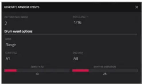
If Event Type is set to Melodic Events:
Use the Start Note or End Note fields to define a specific note range over which the events will be generated.
Tap the Legato checkbox to enable or disable legato.
When on, the generated notes will be extended or shortened to create a long, unbroken phrase from the first note event's start point to the last note event's end point. Each note event will sustain until another note event starts. If multiple note events start at the same time (and are not the last note events), their lengths will become identical.
When off, the generated notes will use the duration set by the Note Length menu.
Use the Polyphony field to select to set the maximum number of note events that can be sounding simultaneously in the track (1–8).
Tap the Constrain Notes to Scale checkbox to determine whether or not the notes will use a scale.
When on, the notes will be within the scale determined by the Scale menu.
When off, the notes will be chromatic.
Use the Density (%) slider to set how closely together the events will be placed in the sequence.
Use the Root Note field to set the root note of the scale that the notes will use.
Use the Scale field to select the scale or mode that the generated notes will use.

![GENERATE RANDOM EVENTS Melodic event options STRAW NOTE C2 END NOTE C4 [ ] Legato POLYPOTHY 8 DENSITY IN 75 ☑ Constrain notes to scale ROOT NOTE C SCALE Major](/content/2026/05/883354/images/5a211bf499712ae491398ca374bab5dc4a5a5e02f85ef8b0a18e1c77bfd9ef1c.jpg)
The Split Note Events process divides note events into an equal number of parts.
Use the Into field to set the number of parts note events will be split into.
Tap the Only selected events checkbox to set the process to only affect selected notes. When unchecked, all note events in the sequence will be split.

The Convert to Progression function creates a custom Progression from a melodic MIDI track that you can use to perform with Progressions Note mode.
To set the parameters of the new Progression, use the Progression fields:
Use the Name field to set the progression name.
Use the Root Note field to set the root note.
Use the Scale Type field to set the scale type.
To set the parameters for the chords in the Progression, use the Chord fields:
Use the Chord field to select a chord from the progression to edit.
Use the Name field to rename the selected chord.
Use the Type field to select to set the type of chord: Root, Normal or Below Root.
Tap the Play button to play the selected chord.
Tap Do It to convert the progression and close the window, or tap the X, Close or anywhere outside the window to close the window and return to the previous screen.

Velocity/Automation Lane
Grid View also contains a velocity/automation lane where you can easily adjust note velocities and automation parameters.
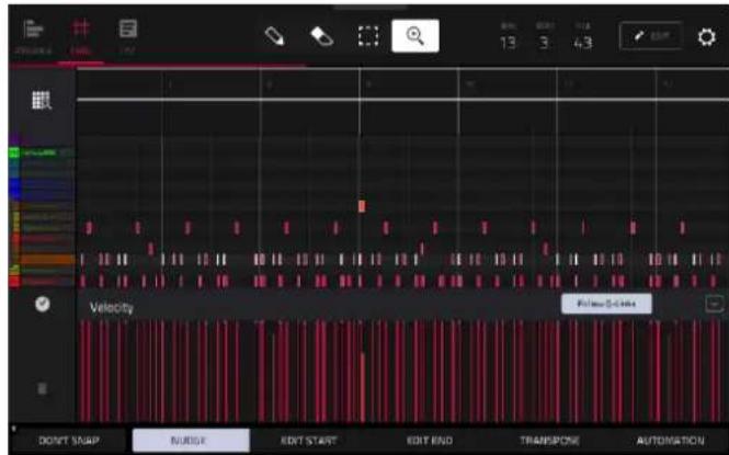
The velocity/automation lane in the Grid Editor.
To show or hide the velocity/automation lane:
- Tap the up arrow (∧) button in the lower-right corner to show the velocity/automation lane.
- Tap the down arrow (v) to hide the velocity/automation lane.
When editing velocity, each note's velocity is represented by a vertical bar. The higher and redder the bar is, the higher the velocity is. Yellow bars indicate a lower velocity. Bars with a gray line at the top indicate a currently selected note.
To adjust the velocity of the selected notes, tap Velocity at the bottom of the screen, and then use the data dial or - / + buttons.
To add automation to a track:
- Select a MIDI Track or Audio Track, and then press Menu and tap Grid View to open Grid View.
- Tap the up arrow on the parameter bar to expand the velocity/automation lane.
- By default, Velocity is shown in this lane for MIDI tracks and TRK: Volume is shown for Audio tracks. Double-tap this field to open the Parameter drop-down menu.
- In the menu that appears, tap Add New to add an automation parameter. You can choose from a variety of parameters depending on the type of track, insert effects added and other options.
To edit automation, do any of the following in Grid View:
- Use the pencil tool to draw your automation in the automation lane.
- Use the eraser tool to erase automation points. If you erase all automation points, the parameter will be removed.
- Tap the trash can icon to delete all automation for the selected parameter at once.
When editing Probability automation, the blue bars represent the probability that the note will play. When editing Ratchet automation, the blue bars represent the ratchet subdivisions for the selected notes, shown as dotted lines on the original note.
Step Sequencer

The Step Sequencer lets you create or edit sequences by using the pads as "step buttons," simulating the experience of a traditional step-sequencer-style drum machine. This is available for MIDI tracks only, not audio tracks.
You can also create and edit automation using the Step Sequencer.
To enter the Step Sequencer, press Menu, and then tap Step Sequencer.

bar
| Category | Value | |---|---| | Track Length | 32 | | Track SEQ | 98.00 | | BMA | 6 | | BLAT | 3 | | TCK | 24 | | PAD | 16 | | AOS | 6 | | PARAMETER | 16 | | TIME DIV | 16 | | 1-16 | < | | NUDGE | > | | INPUT STOPS | 0 | | TC | - | | BAR | + | | PAD SEL | - | | PAD | + |The top of the screen shows the track name and information as well as project and timing information.

The Track field shows the name of the current track.
Tap the Track Length field to set how long the track is in beats. When the SEQ button is on, the track length will follow the Sequence length. When this button is off, use the Bars:Beats:Ticks values to set the exact track length.
Tip: This feature lets you maintain tracks of different lengths. For instance, you could play a 1-bar drum sequence repeatedly under a 4-bar bass line.
Use the BPM field to adjust the tempo of the project.
To set whether the sequence follows its own tempo (Seq) or a global tempo (Gbl), tap the Seq/Gbl button next to the BPM field. Alternatively, press and hold Shift and then press Tap.
The time counter at the top of the screen indicates the current playhead position.
Click the gear icon to open the Step Sequencer configuration window:
Use the Velocity field to set the default step velocity. This applies to notes added using the hardware pads or by tapping the step buttons on the screen.
Use the Step Size field to set the value that determines how many steps each bar of the sequence will have. The T indicates a triplet-based value. This will also adjust the current Timing Correct (TC) value, which can be accessed by tapping TC at the bottom of the Step Sequencer screen.
Use the Auto-Scroll selector to set how the screen behaves relative to the audio playhead:
Off: The grid will not move at all.
Page: The grid will move to the "next page" to follow the audio playhead.
Use the Automation field to determine whether Step Automation is Unlocked from the grid or Locked to Step Length. When set to the latter, changes to automation will only affect the current step. See the following section for more about sequencing automation.

bar
| Track | Sequence | Value | |---|---|---| | 1 | TC | 16 | | 2 | BAR | 16 | | 3 | BAR | 16 | | 4 | BAR | 16 | | 5 | BAR | 16 | | 6 | BAR | 16 | | 7 | BAR | 16 | | 8 | BAR | 16 | | 9 | PAD SEL | 16 | | 10 | PAD SEL | 16 | | 11 | PAD SEL | 16 | | 12 | PAD SEL | 16 | | 13 | PAD SEL | 16 | | 14 | PAD SEL | 16 | | 15 | PAD SEL | 16 | | 16 | PAD SEL | 16 | | 17 | PAD SEL | 16 | | 18 | PAD SEL | 16 | | 19 | PAD SEL | 16 | | 20 | PAD SEL | 16 | | 21 | PAD SEL | 16 | | 22 | PAD SEL | 16 | | 23 | PAD SEL | 16 | | 24 | PAD SEL | 16 | | 25 | PAD SEL | 16 | | 26 | PAD SEL | 16 | | 27 | PAD SEL | 16 | | 28 | PAD SEL | 16 | | 29 | PAD SEL | 16 | | 30 | PAD SEL | 16 | | 31 | PAD SEL | 16 | | 32 | PAD SEL | 16 | | 33 | PAD SEL | 16 | | 34 | PAD SEL | 16 | | 35 | PAD SEL | 16 | | 36 | PAD SEL | 16 | | 37 | PAD SEL | 16 | | 38 | PAD SEL | 16 | | 39 | PAD SEL | 16 | | 40 | PAD SEL | 16 | | 41 | PAD SEL | 16 | | 42 | PAD SEL | 16 | | 43 | PAD SEL | 16 | | 44 | PAD SEL | 16 | | 45 | PAD SEL | 16 | | 46 | PAD SEL | 16 | | 47 | PAD SEL | 16 | | 48 | PAD SEL | 16 | | 49 | PAD SEL | 16 | | 50 | PAD SEL | 16 | | 51 | PAD SEL | 16 | | 52 | PAD SEL | 16 | | 53 | PAD SEL | 16 | | 54 | PAD SEL | 16 | | 55 | PAD SEL | 16 | | 56 | PAD SEL | 16 | | 57 | PAD SEL | 16 | | 58 | PAD SEL | 16 | | 59 | PAD SEL | 16 | | 60 | PAD SEL | 16 | | 61 | PAD SEL | 16 | | 62 | PAD SEL | 16 | | 63 | PAD SEL | 16 | | 64 | PAD SEL | 16 | | 65 | PAD SEL | 16 | | 66 | PAD SEL | 16 | | 67 | PAD SEL | 16 | | 68 | PAD SEL | 16 | | 69 | PAD SEL | 16 | | 70 | PAD SEL | 16 | | 71 | PAD SEL | 16 | | 72 | PAD SEL | 16 | | 73 | PAD SEL | 16 | | 74 | PAD SEL | 16 | | 75 | PAD SEL | 16 | | 76 | PAD SEL | 16 | | 77 | PAD SEL | 16 | | 78 | PAD SEL | 16 | | 79 | PAD SEL | 16 | | 80 | PAD SEL | 16 | | 81 | PAD SEL | 16 | | 82 | PAD SEL | 16 | | 83 | PAD SEL | 16 | | 84 | PAD SEL | 16 | | 85 | PAD SEL | 16 | | 86 | PAD SEL | 16 | | 87 | PAD SEL | 16 | | 88 | PAD SEL | 16 | | 89 | PAD SEL | 16 | | 90 | PAD SEL | 16 | | 91 | PAD SEL | 16 | | 92 | PAD SEL | 16 | | 93 | PAD SEL | 16 | | 94 | PAD SEL | 16 | | 95 | PAD SEL | 16 | | 96 | PAD SEL | 16 | | 97 | PAD SEL | 16 | | 98 | PAD SEL | 16 | | 99 | PAD SEL | 16 | | Note: The actual values for the bars are not provided in the code. The data is extracted from the `data` array in the code editor.The TC icon opens the Timing Correct (TC) window, which contains various settings to help quantize the note events in your sequence.
Use the Bar - / + buttons at the bottom of the screen to select the bar of the sequence whose steps you want to enter or delete. The current bar number is shown in the upper-left corner.
Use the Pad -/+ buttons at the bottom of the screen to select the pad whose steps you want to enter or delete. The current pad number is shown in the upper-left corner.
Hold Shift and use the Track -/+ buttons to select a track to sequence on.
Hold Shift and tap the Clear button to clear all steps in the current sequence.
Hold Shift and tap the Clear Page button to clear all steps in the current page view.
To enter or delete steps in a sequence:
- Use the Pad -/+ buttons at the bottom of the screen to select the pad whose steps you want to enter or delete. The current pad number is shown in the upper-left corner. You can also hold Shift and tap a pad to select it.
Alternatively, use the Pad Select feature: Tap and hold Pad Sel, press the desired pad, and then release Pad Sel. You can also use Pad Select as a "latching" feature: tap Pad Sel so it is activated, press the desired pad, and then tap Pad Sel once more so it is deactivated.
- Use the Bar -/+ buttons at the bottom of the screen to select the bar of the sequence whose steps you want to enter or delete. The current bar number is shown in the upper-left corner.
- Press the pads of your MPC hardware, or tap a button at the bottom of the sequencer. Each pad corresponds to a step in the bar and will light with a color corresponding to its velocity.
Keep in mind that for time divisions larger than 16, the bar's steps will be represented by multiple pad banks. In this case, use Pad Bank Buttons to view all the steps within a bar.
For time divisions larger than 16, the bar's steps will be represented by multiple pad banks. In this case, use the left and right arrows (< and >) by the step numbers (1–16, 17–32, etc.) to change which steps are shown in the sequencer.

Alternatively, use the Pad Bank Buttons.
To adjust the velocities of the steps, do any of the following:
- Tap anywhere on the velocity bar of a step. The top of the velocity bar will jump to that point.
- Use the slider on the right edge of the screen to increase or decrease the velocities of all steps.
- Turn the Q-Link knob that corresponds to that step (the Q-Link knobs must be in the Screen edit mode). Setting a value of 0 (Off) will delete the step.
Use the Nudge < and Nudge > arrows to shift the entire pattern left or right (respectively) by one step. This is useful for experimenting with different rhythmic permutations.
Use the slider on the right edge of the screen to increase or decrease the velocities of all steps.
Use the Flip Steps button to switch which steps have notes entered and which do not have notes. Steps that previously had no notes will now have notes at full velocity (127). Steps that previously had notes will now be empty.

Tap Presets to show or hide the preset velocity controls. These controls let you manipulate and transform the velocities of the current bar in the sequence.
The first button will apply ascending or descending velocities to the steps. Each time you tap it, it will cycle through these options:
• The velocities will ascend to a single peak at the end of the bar.
- The velocities will ascend to two peaks—one after each half of the bar.
- The velocities will ascend to four peaks—one after each quarter of the bar.
• The velocities will descend from a single peak at the start of the bar.
- The velocities will descend from two peaks—one after each half of the bar.
- The velocities will descend from four peaks—one at the start each quarter of the bar.

The second button will set the velocities of the steps to be at the maximum value (127) or minimum values (1), depending on their position in the bar. Each time you tap it, it will cycle through these options:
- The velocities of the first half of the bar will be set to 1. The velocities of the second half will be set to 127.
- The velocities of the first and third quarters of the bar will be set to 1. The velocities of the second and fourth quarters will be set to 127.
- The velocities of the first, third, fifth, and seventh eighths of the bar will be set to 1. The velocities of the second, fourth, sixth, and eighth eighths will be set to 127.
- The velocities of the first half of the bar will be set to 127. The velocities of the second half will be set to 1.
- The velocities of the first and third quarters of the bar will be set to 127. The velocities of the second and fourth quarters will be set to 1.
- The velocities of the first, third, fifth, and seventh eighths of the bar will be set to 127. The velocities of the second, fourth, sixth, and eighth eighths will be set to 1.
The third button will apply ascending or descending velocities to the steps. Each time you tap it, it will cycle through these options:
- Across the entire bar, the velocities will ascend to a peak and then descend from it.
• In each half of the bar, the velocities will ascend to a peak and then descend from it.
• In each quarter of the bar, the velocities will ascend to a peak and then descend from it. - Across the entire bar, the velocities will descend from a peak into a valley and then ascend back up to the peak.
- In each half of the bar, the velocities will descend from a peak into a valley and then ascend back up to the peak.
- In each quarter of the bar, the velocities will descend from a peak into a valley and then ascend back up to the peak.
The fourth button will swap the first half and second half of the bar. In other words, the first half of the bar will become a mirrored image of the second half, and vice versa.
The fifth button will invert the velocities of all steps with entered notes. The sum of the old and new velocities will equal 127. The exception is a velocity of 127 or 1 as a step with a note cannot have a velocity of 0.
Examples:
Steps with velocities of 40 will now have velocities of 87, and vice versa.
Steps with velocities of 75 will now have velocities of 52, and vice versa.
Steps with velocities of 127 will now have velocities of 1, and vice versa.

Step Automation
You can also create and edit automation using the Step Sequencer.
To add a step automation parameter:
-
By default, the Parameter field of the Step Sequencer displays Velocity for MIDI tracks and TRK: Volume for audio tracks. Double-tap this field to open the dropdown menu.
-
In the menu that appears, tap Add New to add an automation parameter. You can choose from a variety of parameters depending on the type of track, insert effects added and other options.

bar
| Channel | Value | |---------|-------| | 13 | 13 | | 16 | 16 |To edit step automation, do any of the following:
- Tap and drag your finger in the step area to freely draw step values.
- Press and hold the Q-Link button, and then tap Screen to set the Q-Link knobs to Screen Mode. While viewing the step sequencer, you can use the Q-Link knobs for tactile control of each step's automation value, emulating traditional knob-based step sequencers. While it is being adjusted, the current automation value will be shown next to the Parameter field, as well as in the display strip above the knobs (MPC X only).
- Press and hold Shift and tap Clear to clear all automation for the selected parameter in the selected sequence.
- Press and hold Shift and tap Clear Page to clear all automation for the selected parameter in the current page view of the selected sequence.
- Use the Nudge < and > buttons to shift the current automation parameter to the left or right at the current Timing Correct value.
- Use the slider on the right side to increase or decrease the parameter values for all automation steps in the visible time range.
- Tap Presets and use the buttons to apply the presets to the step automation.
Note: When editing step automation, if a step is not activated, a darkened step bar will indicate the current parameter value at that step, based on the last active step.
List Edit Mode

List Edit Mode has some of the features of Grid View—as well as some additional ones—but with a different interface/workflow.
To enter List Edit Mode, press Menu and then tap List Edit. You can also tap List at the top of the screen in Arrange Mode or Grid View Mode.

When viewing main Events screen, tap the Tempo tab at the bottom of the screen to switch to the Tempo screen, where you can add and adjust tempo change events.
The Time Counter at the top of the screen indicates the current playhead position.
The TC icon opens the Timing Correct (TC) window, which contains various settings to help quantize the note events in your sequence.
Press and hold Shift and tap the TC icon to enable or disable global timing correct.
The View menu lets you select what type of events are shown in the list.
All: Select this option to show all event types.
Notes: Select this option to show only notes.
Aftertouch: Select this option to show only aftertouch messages.
MIDI Automation: Select this option to show only MIDI automation events.
Track Automation: Select this option to show only track automation events.
Pitch Bend: Select this option to show only pitch bend events.
Control Change: Select this option to show only MIDI CC messages.
Program Change: Select this option to show only MIDI program change messages.
Ch Pressure: Select this option to show only channel pressure messages.
Mute: Select this option to show only mute events for tracks and pads.
MPCe: Select this option to show only MPCe events such as Pad X/Y position.
The automation button indicates the global Automation state.
Tap the modifier icon to open the Note Modifier Settings window, where you can adjust the modifier playback mode for the following modifier types:
Filter (Cutoff, Resonance, Filter Envelope Amount)
Envelope (Attack, Decay, Release)
Sample (Sample Layer, Sample Slice)
Tuning (Coarse Tuning, Fine Tuning)
Mix (Pan, Level)
When the modifier type is set to Absolute, a note with an active modifier for that type will use the modified value specified by the note event directly, ignoring any values set in Track Edit, Sample Edit, or Pad Mixer which would affect the modifier value, and ignore pad automation that would affect the modified value.
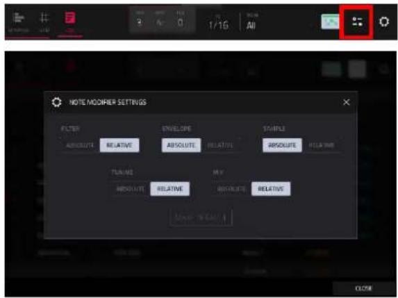
When the modifier type is set to Relative, a note with an active modifier for that type will use the modified value as an offset (or scale, in the case of Level) of the existing state, taking into account any values set in Track Edit, Sample Edit, or Pad Mixer which would affect the modifier value, as well as be affected by pad automation that affects the modified value. Relative modifier may be set beyond the limit of the underlying value. For example, a pad with an Envelope Attack value of 10 could have a -100 modifier, in which case the note would be played back with an Attack value of 0.
Modifier playback mode settings will save with your project. Tap the Make Default button to make the current configuration the default modifier playback mode setting for all new projects. This can be reset using the Reset Preferences function in the Preferences menu.
Note: Legacy MPC projects are loaded with Sample and Envelope set to Absolute, and all other groups set to Relative. Envelope modifiers for legacy projects will also not ignore automation even despite being set to Absolute. This is to ensure the sound of old projects is retained. Interacting with the modifier playback Envelope setting in any way will remove this behavior, and from that point the Envelope modifiers will ignore automation as normal.
Tap the gear icon to open the List View settings window, where you can configure the following settings:

Use the Hitting Pad Selects All Events selector to turn the feature on or off. When On, pressing a pad will automatically select all note events for that pad in the selected sequence on that track. When set to Off, pressing a pad will simply play its sound without selecting any note events.
Use the Auto-Advance on Step Record selector to turn the feature on or off. When set to On, pressing a pad when the track is record-armed will move the audio playhead forward by a length determined by the current Time Division setting in the Timing Correct (TC) window. When set to Off, pressing a pad when the track is record-armed will not change the audio playhead position.

Use the Mod Type Selection field to set whether changing the Mod Type changes only the Selected event or All events of the selected type.
Use the Auto-Scroll selector to set how the screen behaves relative to the audio playhead.
Follow: The list will scroll along in the background while keeping the audio playhead centered.
Page: The list will move to the "next page" to follow the audio playhead.
Off: The list will not move at all.
These functions also apply to Grid View and Sample Edit Mode.
| # | TIME | PAD/NOTE | LENGTH | VELOCITY | MOD TYPE | VALUE | PROB | RAT |
The contents of the sequence will be shown as a list of events, with the following parameters:
: This is the number of the note event.
Time: This is the position of the note event in bars, beats, and ticks. If multiple note events occur at the same time, additional note events will be listed immediately below, but their Time values will be grayed out.
The Event Type icon indicates the type of event (e.g., Note, Aftertouch, Track Automation, etc.). See the list of icons below showing the different types of events.
Pad/Note: This is the pad and/or corresponding MIDI note number. For drum tracks, you will see the pad number. For keygroup tracks, plugin tracks, and midi tracks, you will see the note.
Length: This is the length of the note event in ticks.
CH: This is the MIDI Channel of the event.
Velocity: This is the velocity of the note event with its corresponding color.
Mod Type: This is the type of modifier used on the note event via automation.
Value: This is the value of the modifier automation.
Prob: This is the probability percentage of the event.
Rat: This is the ratchet value of the event.

The red arrow (▶) on the left side of the list represents the audio playhead's current position. If your sequence is playing, the arrow will move accordingly.
The following icons indicate the corresponding types of events:
| Note |
| MIDI Automation (Volume, Pan, Mute, Solo) |
| MIDI CC Automation (0–127) |
| MIDI Parameter Automation (Aftertouch, Pitchbend, Channel Pressure, or Program Change) |
| Mixer Automation (Volume, Pan, Mute, Solo, or Send 1–4) |
| Mixer Parameter Automation (options vary based on the type of track) |
| Track Insert Effect Automation (options vary based on the effect) |
| Pad/Keygroup Mixer Automation (Level, Pan, Pad Mute, Pad Solo, or Send 1–4) |
| Pad/Keygroup Parameter Automation (options vary based on the type of track) |
| Pad/Keygroup Insert Effect Automation (options vary based on the effect) |
| Sequence Tempo Automation |

Tap an event to select it. Press and hold Shift to select multiple events.
To insert a note event, press Rec so the button is lit, and then press a pad. A note event will be created at the current location using the pad you pressed. You can keep pressing additional pads, which will continue to insert each press as a single note event in the order you pressed them (similar to a step sequencer). Press Stop to exit this function.
Note: Depending on the Auto-Advance on Step Record setting, the current time position will either advance each time you press a pad or remain in place. See the earlier description of Auto-Advance on Step Record to learn about this.
Alternatively, press the Insert button at the bottom of the screen to open the Insert Event window:
Use the Bar:Beat:Tick fields to set the location where you want to add an event.
Use the Type field to set what kind of event you would like to add: Note, Pad Automation, Mixer Automation or MIDI Automation. When the Tempo tab is selected, this field is locked to Sequence Automation.
Use the Pad and/or Parameter fields to set the additional values or settings based on the type of event. When the Tempo tab is selected, this field is locked to Parameter >Sequence Tempo.

Tap Do It to add the event.
Tap Cancel, the X or anywhere outside the window to close the Insert Event window and return to List Mode.
To edit the Pad/Note, Length, Velocity, Tempo, or numeric Value of an event, tap the value to select it, and then use the data dial or - / + buttons to change the value. Alternatively, double-tap it and use the numeric keypad that appears to enter a value (for Length, Velocity, or numeric Value only).
To edit the Length of an event according to your Timing Correct settings, tap the value to select it, and then press and hold Shift and use the data dial or - / + buttons to change the value.
To shift the Pad/Note of an event by pad bank, tap the value to select it, and then press and hold Shift and use the data dial or - / + buttons to change the pad bank.
To turn a Solo/Mute event on or off, tap the desired setting on the On/Off switch. Alternatively, tap the On/Off switch to select it, and then use the data dial or - / + buttons to change the value.
To move an event, tap it to select it, tap Nudge at the bottom of the screen, and then use the data dial or - / + buttons to shift the event up or down. Repeat this for other events, or tap Nudge again to turn the feature off.
To move an event according to your Timing Correct settings, tap the Time value to select it, and then press and hold Shift and use the data dial or - / + buttons to change the value.
To play an event, tap it to select it, and then tap Play (▶) at the bottom of the screen. This works with note events only.
To delete an event, tap it to select it, and then tap Delete at the bottom of the screen.
Track Edit Mode

Track Edit Mode (formerly Program Edit Mode) contains all parameters for editing your Tracks.
To enter Track Edit Mode, do either of the following:
- Press Menu, and then tap Track Edit.
- Press Prog Edit (MPC X, MPC One) or Edit (MPC Key 61, MPC Key 37).
For drum tracks, this mode includes the parameters of all eight layers as well as all synthesis parameters and insert effect settings. See the Drum Tracks section to learn more.
For keygroup tracks, this mode contains slightly more parameters than drum tracks. See the Keygroup Tracks section to learn more.
For plugin tracks, skip to Plugin Tracks to learn more.
For MIDI tracks and CV tracks, skip to MIDI Tracks and CV Tracks to learn more.
Double-tap the Track field at the top of the touchscreen to open the Track Settings window. To learn more about these settings, and for more general information on the differences between the types of tracks, please see General Features >Tracks.
Drum Tracks

When using drum tracks, Track Edit Mode lets you edit the parameters for each pad.
To select a pad, press it. Its parameters will appear on the screen immediately.
To view a specific tab of parameters, tap the tabs at the bottom of the screen. Tap the > or < arrows to scroll to view other available tabs. Some tabs such as Samples or Effects have multiple pages, which can be cycled by tapping the tab multiple times.
Tap the Edit All Layers button to enable or disable editing control of all sample layers at the same time. When this is enabled, edits made to sample parameters such as Start/End points or Semi/Fine tuning on any one layer are automatically applied uniformly to all eight layers at once (even if some layers are empty).
Tap the Stems icon to open the Create Stems Function in the Process Sample window. You can use this process to isolate different parts of the sample and separate them into new stem samples.

Click the icons to select or deselect from the following elements to create stems of:
- Vocals: Isolate vocal elements of the track into a stem.
- Bass: Isolate bass elements of the track into a stem.
- Drums: Isolate percussive elements of the track into a stem.
- Other: Isolate other musical textures, such as keys or guitars, into a stem.

Use the Track dropdown menu to select the track where the stems will be added.
The Assign to Pad function determines where the stem separated samples are added. When checked, you can select a pad in the chosen Track using the dropdown menu, and the stems will be added to the first four layers of that pad. When unchecked, the stems will be added to the general project sample pool in the Project Info Browser.
Tap the Use trimmed sample box to trim the source sample between the Start and End points before applying the stem separation process.
Note: To purchase MPC Stems, visit akaipro.com/stems, and then activate your purchase in the Menu > Preferences > Activate Plugins menu.
Tap the keyboard+ icon at the top of the screen to quickly create a keygroup from the selected sample. The new keygroup will be created on a new track and automatically be selected.

Tap the down-arrow icon at the top of the screen (next to the Track field) to open the Flatten Pad window, which renders all samples on a pad as an audio sample and places it on the first layer of that pad.

The resulting sample is the audio signal produced by that pad at full velocity (127) after the pad channel strip, which means that it includes any assigned pad insert effects and the results of warping the sample.
This function is useful if you need to reduce how CPU-intensive a pad or track is by essentially "embedding" the warping and effects in the sample itself. By default, it will use the name of the first sample. This function works for drum tracks only.
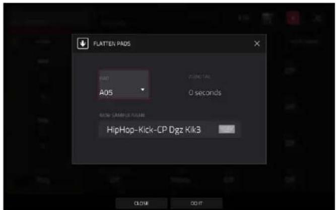
To select the pad, press it or use the Pad menu.
Use the Audio Tail field to set the length of the audio tail. This will add extra seconds to the end of the resulting audio file. This is useful if you are using effects or samples whose sounds exceed the defined audio length (e.g., long reverb or delay, one-shot samples with long decays, etc.). We recommend using an audio tail of at least a couple of seconds.
Tap the Edit Name field and use the virtual keyboard that appears to name the new sample.
Tap Do It to confirm your choice.
Tap Cancel to cancel and return to the previous screen.


Tap the location icon at the top of the screen (on the right side) to open the Edit Zones window, which is a feature for drum tracks. This window displays an overview of any selected pads. Use the Mode selector to set how the selected pads will be edited:

• Current: Only the currently selected pad can be edited.
• Multiple: All selected pads can be edited simultaneously.
• All: All pads can be edited simultaneously.
To close the window, tap Close, the X, or anywhere outside the window.
Global
In the Global tab, you can set the playback mode and tuning for the overall Track.

Global Semi lets you transpose the track up to 36 semitones up or down.
Global Fine provides fine-tuning of the track up to 99 cents up or down.
Global Poly (Polyphony) sets the playback mode for the track's pads. In Mono Mode, only one pad will sound at a time. If a pad is played while another (or the same one) is still playing its sample/samples, the new pad will immediately mute all other currently playing pads in that track. In Poly Mode, several pads can be triggered at the same time (limited only by the total number of voices available).
Level controls the overall volume level of the loaded sample/samples.
Pan controls the overall panning of the loaded sample/samples in the stereo field.
Pad Tuning controls the overall tuning of the loaded sample/samples.
Use the Velocity Scaling field to apply scaling to the incoming velocity. For example, if the scaling is set to 50 and the incoming note velocity is 120, the note velocity would be 60 instead.
Use the Layer Play selector to determine how multiple samples assigned to the same pad are played:
- Cycle (Cyc): Each time the pad is played, it will play the next layer's sample. In other words, the samples will cycle through the layers as follows: 1, 2, 3, 4, 1, 2, 3, 4... etc.
• Velocity (Vel): The pad will switch between layers depending on how hard you press a pad. - Random (Ran): Each time the pad is played, it will play one of its layer's samples at random. When selected, the Random Seed field displays a value between 1–999,999. You can copy and reuse this value to reproduce the same random sequence.
- Crossfade: Crossfade between sample layers using modulation sources like envelopes and LFOs in the Mod Matrix, allowing for wave sequencing or vector synthesis-like effects.
Use the Sample Play selector to determine how much of the sample is played.
• One Shot: The entire sample will play from start to end. Use this when you want to play short sounds.
• Note Off: The entire sample will play from start to end after the pad has been pressed and released.
- Note On: The sample will play only as long as the pad is held. This is better for longer samples so you can control a sound's duration by pressing and holding its corresponding pad.
Use the Pad Polyphony field to determine how the pad's sound behaves when multiple hits are registered. When set to Mono, only one pad will sound at a time. If a pad is played while another (or the same one) is still playing its sample/samples, the new pad will immediately mute all other currently playing pads in that track. When set to Poly, several pads can be triggered at the same time (limited only by the total number of voices available). You can also select a specific number of pads (2–32) so that you can trigger up to this many pads at the same time (unless they exceed the total number of voices available).
Use the Mute Group field to assign the selected pad to one of the 32 available groups. When pads assigned to the same mute group receive MIDI notes, the last pad played will silence all other pads in that mute group. A mute group affects pads within that track only; mute groups do not affect pads in other tracks.
Tip: This feature is useful for programming realistic hi-hats, so only the open or closed hat is heard.
The Simultaneous Play section lets you set up to four pads that can be triggered by pressing one pad only. This function is useful for triggering a stack of sounds (e.g., layered kick drums). Use each Pad field to select the desired pad.
The Mute Targets tab lets you select up to four pads (in the same track) for the currently selected pad. When the currently selected pad is played, it will immediately silence its mute targets. Use each Pad field to select the desired mute target.
Tips:
This feature is useful for programming realistic hi-hats, especially if only the open or closed hat should be heard. This feature is similar to the mute group feature, available for both drum tracks and keygroup tracks.
Samples
Each pad can trigger up to eight samples, which are assigned in eight individual layers. Each layer has identical, independently assignable parameters.
Tap Samples to cycle through its four available tabs.

You can access the Settings window, which lets you configure certain settings in the Samples tab, from any of the four tabs by tapping the gear icon.
Use the Link Slices selector to set how the start point and end point of a slice in a larger sample is set. You can create these slices in Sample Edit Mode > Chop Mode.
When on, changing the start point of a slice will also change the end point of the previous slice. Similarly, changing the end point of a slice will also change the start point of the next slice. Disable Link Slices if you are trying to create slices that use non-contiguous parts of the sample. This is the same as the Link Slices button in Sample Edit Mode.

Use the Loop Lock selector to "link" or "unlink" the loop point from the start point. When on, the loop point is the same as the start point. When off, the loop point is independent from the start point and indicated by a separate loop marker. This is the same as the Loop Lock button in Sample Edit Mode.
Use the Zero Snap selector to enable or disable the Zero Snap feature, which forces start points, end points, and loop points to occur only at the waveform's "zero-crossings." This can help to avoid clicks and glitches when playing a sample. This is the same as the 0 Snap button in Sample Edit Mode.
To close the Settings window, tap Close, the X in the upper-right corner, or anywhere outside the window.
The first Samples tab contains the sample waveform for each layer and controls for its pitch, timing, and playback.

The upper half of the screen shows the waveform of the sample on the currently selected layer. The lower half shows the editing controls.
The waveform display shows the "active" section of the sample waveform. Swipe left or right on the waveform to move through it.
Above the waveform is the timeline, shown in bars, beats, and ticks.
Use the bottom-most Q-Link knob in the fourth bank to zoom in or out of the sample waveform.
Tap each layer number (Layer 1–8) under the waveform to select it. When selected, its sample waveform will be shown in the upper half of the screen and its settings will be shown in the lower half.
Use the Sample field to select the sample file for that layer. Remember that the sample has to be loaded into the project's sample pool beforehand. For information on how to load samples into a project, please see the Browser chapter.
Important: The parameters in the Samples tabs work in conjunction with Chop Mode (in Sample Edit Mode). Here's how it works:
When working in Sample Edit Mode and using Chop Mode to divide a sample into slices for your pads, you can convert a slice using Non-Destructive Slice or Pad Parameters.
A Non-Destructive Slice will let its pad to refer to that slice when you press it; the original sample remains intact, and each slice marker is like a "bookmark" for a pad. In Track Edit Mode, you'll see that the pad/layer to which it's assigned has its Slice drop-down menu set to the corresponding slice number in the original sample. Playing that pad will cause it to refer to that slice marker like a "bookmark" instead of creating an entirely new sample of that slice. This means that you no longer have to clutter your project with a new sample for every slice (though you can still use this earlier method, if you prefer).
A slice converted using Pad Parameters is very similar to a non-destructive slice described above. The difference is that in Track Edit Mode, the pads/layers they're assigned to have their Slice drop-down menus set to Pad (instead of the slice number), and the start and end points will correspond to the slice markers in the original sample.
Tap the trash can icon next to the sample field to remove the file from the layer.

The green/S marker and red/E marker are the start point and end point (respectively). These two points define the region of the sample that will be played.
To move the start point or end point, do any of the following:
- Tap and drag the S or E marker left or right.
• Use the Start or End fields shown below the waveform. - When the Q-Links are set to screen mode, you can use them to adjust the start and end points in fine and coarse adjustments. For MPC hardware with four Q-Links, the first bank adjusts the start point, and the second bank adjusts the end point.
Note: When Loop Lock is on, the loop position (as determined by the Loop field, if enabled) is the same as the sample's start point. When off, the loop position is independent from the start point.
Use the Loop field to determine the position where the sample's playback will repeat when Pad Loop is activated.
Note: When Loop Lock is on, the loop position is the same as the sample's start point. When off, the loop position is independent from the start point.
Use the Tail Length and Tail Start fields to add adding extra audio tail to any chopped sample. This is useful for things like making an abrupt end to a sample sound more natural or adding experimental looping effects to a sample. The Tail Length parameter enables the sample tail and set its total length, and the Tail Start parameter sets the starting point within the tail for looping.
Use the Repeats field to set a sample to play a specified number of times. First make sure Pad Loop is set to On, then use this field to set the number of times you want to have the sample loop between the Sample Loop and End points. For example, a value of 4 would repeat the selected area of the sample 4 times.
Note: The behavior difference between Repeats set to 0 and 1 is only evident when a Pad's Sample Play parameter is set to Note On. Then, when hold a note, a Repeat value of 0 will create infinite repeats, and a value of 1 will play a sample one time through.

Use the Slice field to select what part/parts of the sample will play:
• All: The entire sample will play.
- Pad: The sample will play from the Pad Start position to the Pad End position, described earlier. This also lets you activate Pad Loop (if the Sample Play field in the LFO Modulation tab is set to Note On).
- Slice 1, 2, 3, etc.: If you have sliced the sample in Chop Mode, you can select which slice will play when you trigger the pad.
When Slice is selected, you can tap the Slice Motion icon to trigger a different sample slice each time a pad is played.
Use the Motion setting to select Increment, which increments the slice number with each new note event, or Random, which plays your slices in a random order.
Use the Slice field to set the starting slice.
Use the Cycles field to select how many of the slices are played.

Tap the pad repeatedly, or turn Note Repeat on and hold the pad, to hear the slices of your chopped loop play.
Use the Play Offset field to shift a sample window between the Start, End, and Loop points across the sample without altering their relative positions. For example, if you set these points to frame the first 1/16th note of a one-bar sample, you can use the Play Offset to shift that window to different 1/16th note positions within the sample. You must retrigger the sample to hear offset changes.
Use the Reverse button to select in which direction the sample will play. When on, the sample will play in reverse. When off, the sample will play in the normal forward direction.
Use the Pad Loop button to cycle through the available Pad Loop modes.
Important: For Pad Loop to work, you must (1) set the Sample Play field (in the Global tab) to Note On instead of One Shot and (2) set the Slice field (in the first Samples tab) to Pad instead of All or a slice number.
• Off: The sample will not loop.
- Forward: You can hold down the pad to cause that sample to repeat from the Loop Position to the end of the sample. Release the pad to stop the repeating playback.
- Reverse: You can hold down the pad to cause that sample to play in reverse, repeating from the end of the sample to the Loop Position. Release the pad to stop the repeating playback.
- Alternating: You can hold down the pad to cause that sample to play from the Loop Position to the end of the sample and then play in reverse until it reaches the Loop Position again. This will repeat as long as you are holding the pad down. Release the pad to stop the repeating playback.
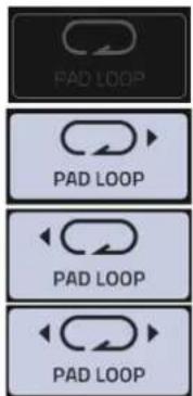

Tap BPM Sync to enable or disable BPM Sync.
When BPM Sync and Warp are both enabled, the sample's BPM will be "locked" to the tempo of the project.
When BPM Sync is disabled but Warp is enabled, the sample will be independent of the tempo of your project—use the Stretch field to lengthen or shorten a sample.
Tap Warp to enable or disable warping of the sample.
When enabled, lengthening or shortening the sample (based on the BPM) will not change its pitch.
When disabled, lengthening or shortening the sample will also change its pitch and vice versa.
Note: The Warp algorithms are very CPU-intensive and can result in audio drop-outs during playback if used too freely. Be mindful of how (and how often) you use the warp function. You can reduce the CPU resources required by doing any/all of the following:
Avoid using extreme Stretch values.
Minimize the amount of pitch adjustment (e.g., the Semi and Fine parameters) of warped audio.
Avoid warping very small sample regions.
Warp as few samples or sample regions as possible (i.e., reduce the number of total number of voices of the polyphonic limit that use the Warp algorithm at a given time), especially instances where the warped regions start at the same time.
Avoid rapidly triggering samples that are warped.
If you have warped samples used in a drum kit, consider using the Flatten Pad function to consolidate the affected pad's layers into one audio sample (see here to learn about this). After you flatten the pad, its sample/samples no longer need to be warped.
Semi lets you transpose the selected layer up to 36 semitones up or down. This will affect the length of the sample (if Warp is off). This is the same as the Semi knob on the second Samples tab. The analyzed Key of the sample is displayed next to the Semi field and will adjust based on this value.
Fine provides fine-tuning of each layer by cents. This will affect the length of the sample (if Warp is off). This is the same as the Fine knob on the second Samples tab.
Use the Stretch field to set the "stretch factor," which affects how the sample is warped (if Warp is on).
Use the BPM field to enter a tempo, which affects how the sample is warped (if Warp is on).
Use the Algorithm field to select the audio warp algorithm for the sample: Default, Pro Ten, or Repitch. The Default algorithm can be set in the Preferences >Audio/Export menu.
Note: Changing the Algorithm setting here will override the Preferences setting.
The second Samples tab (Tune/Mix) contains controls for its pitch, volume level and panning.
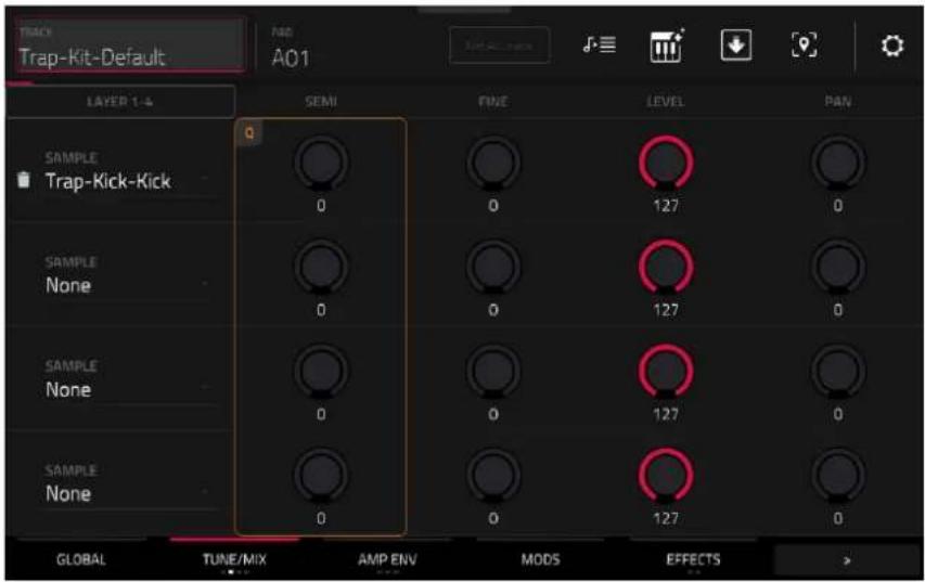
Tap the Layer 1-4/Layer 5-8 button to toggle between visible layers.
Use the Sample field to select the sample file for that layer. Tap the trash can icon next to the sample field to remove the file from the layer.
Semi lets you transpose the selected layer up to 36 semitones up or down. This will affect the length of the sample (if Warp is off). This is the same as the Semi field on the first Samples tab.
Fine provides fine-tuning of each layer by cents. This will affect the length of the sample (if Warp is off). This is the same as the Fine field on the first Samples tab.
Level lets you adjust each layer's volume, letting you control the "balance" of the samples assigned to the pad.
Pan adjusts the stereo placement of the respective layer.
The third Samples tab (Velocity) contains the control for its offset and velocity range.
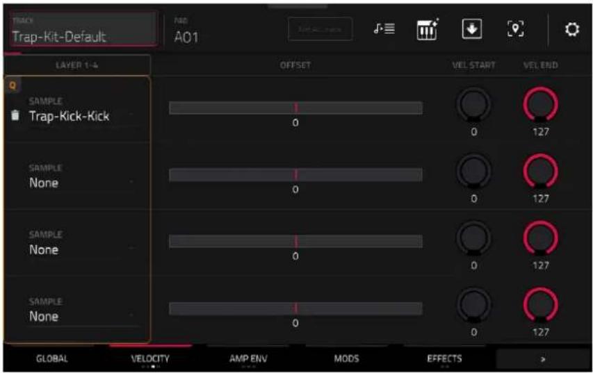
Tap the Layer 1-4/Layer 5-8 button to toggle between visible layers.
Use the Sample field to select the sample file for that layer. Tap the trash can icon next to the sample field to remove the file from the layer.
Use the Offset slider to determine a time offset for the sample's playback.
- Positive values (right of center): When the pad is played, playback will start immediately but at a later point in the sample specified by the offset value.
- Negative values (left of center): When the pad is played, playback will be delayed by the amount specified by the offset value.
Use the Vel Start and Vel End knobs to define the velocity range of each layer.
A range from 0 to 127 lets the layer respond to the entire velocity range which is input from the respective pad while, for example, a range from 100 to 127 lets the layer respond only to higher velocity levels. By assigning several samples of one instrument, you can create a realistic-sounding “multi-sample” by adjusting the velocity ranges of each layer accordingly.
For example, you may have three samples of a drum hit with low force, medium force, and high force. You can set each sample to a layer and set the Velocity ranges so only low velocities trigger the low-force sample, only mid-range velocities trigger the medium-force sample, and only high velocities trigger the high-force sample.
The fourth Samples tab (Random) contains the controls for adding randomization to sample parameters such as pitch, level and panning.
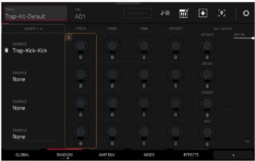
Tap the Layer 1-4/Layer 5-8 button to toggle between visible layers.
Use the Sample field to select the sample file for that layer. Tap the trash can icon next to the sample field to remove the file from the layer.
Use the Pitch knobs to adjust the amount of randomization applied to each sample layer's pitch.
Use the Level knobs to adjust the amount of randomization applied to each sample layer's volume.
Use the Pan knobs to adjust the amount of randomization applied to each sample layer's stereo placement.
Use the Offset sliders to adjust the amount of randomization applied to each sample layer's time offset.
The All Layers section will apply randomization to all sample layers for the following envelope parameters: Attack, Decay, Cutoff and Resonance. Use the Depth slider to control the amount of envelope randomization applied overall.
Envelopes
Tap Envelopes to cycle through its three available tabs.

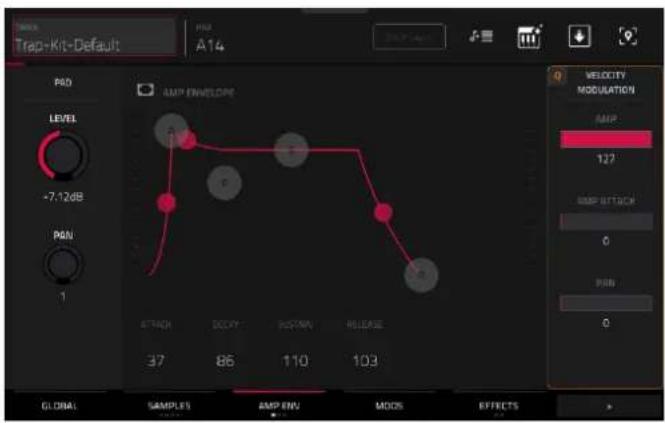
The first Envelope tab contains the amplitude modulation envelope.
Pad Level controls the overall volume level of the loaded sample/samples.
Pad Pan controls the overall panning of the loaded sample/samples in the stereo field.
The Amp Envelope controls affect level changes over time. Use the fields or tap and drag the “handles” of the envelope to shape the envelope or time-variant modulation output. Adjust the envelope’s influence on the filter frequency with the Env knob. See the later Anatomy of an Envelope section to learn about the envelope parameters.
The Velocity Modulation controls determine how much the velocity affects the volume level of the amplitude envelope (Amp), the attack of the amplitude envelope (Amp Attack), and/or the panning of the sound (Pan).
When you press a pad softly, only minimal modulation is applied. When you press it harder, the modulation amount also gets stronger depending on the setting of the corresponding slider.
The second Envelope tab contains the filter modulation envelope.

Use the Type field to select a filter for the selected pad. See Appendix > Glossary > Filter for an explanation of the available filter types.
Use the Cutoff knob to set the cutoff frequency for low-pass and high-pass filter types or the center frequency for band-pass and band-stop filter types.
Use the Reso knob to set the resonance/emphasis of the frequencies around the cutoff point.
Tip: Use values lower than 80 to give more brilliance to the sound. At values higher than 80, the sound will result in a strong audible boost around the cutoff frequency.
The Filter Envelope controls affect the filter frequency. Use the fields or tap and drag the “handles” of the envelope to shape the envelope or time-variant modulation output. Adjust the envelope’s influence on the filter frequency with the Depth knob. See the later Anatomy of an Envelope section to learn about the envelope parameters.
Use the Depth slider to determine the amount of influence the filter envelope has on the cutoff frequency. Higher settings will increase the modulation of the filter by the envelope; lower settings will result in only subtle changes of the filter Cutoff over time.
Tip: To give a sound a more distinctive attack, increase the Depth setting and set low Atk and Decay values as well as a medium-low Sust value of the Filter Envelope. This will start a sound with the filter opened and close it shortly afterward, giving it a bright start followed by a darker sustain. String sounds, on the other hand, can sound much more “alive” with low Depth settings and a high Atk value, resulting in a slight fade-in of the higher frequencies.
The Velocity Modulation controls determine how much the velocity affects the cutoff frequency of the filter envelope (Cutoff), the attack phase of the filter envelope (Attack), and/or depth of influence the filter envelope has on the cutoff frequency (Depth).
When you press a pad softly, only minimal modulation is applied. When you press it harder, the modulation amount also gets stronger depending on the setting of the corresponding slider.
The third Envelope tab contains the pitch modulation envelope.

Global Semi lets you transpose the pad up to 36 semitones up or down. This will affect the length of the sample (if Warp is off). This is the same as the Semi field on the Global tab.
Global Fine provides fine-tuning of each layer by cents. This will affect the length of the sample (if Warp is off). This is the same as the Fine field on the Global tab.
The Pitch Envelope controls affect the pad's pitch. Use the fields or tap and drag the "handles" of the envelope to shape the envelope or time-variant modulation output. Adjust the envelope's influence on the pitch with the Depth slider. See the later Anatomy of an Envelope section to learn about the envelope parameters.
The Velocity Modulation control determines how much the velocity affects the pitch envelope (Pitch).
When you press a pad softly, only minimal modulation is applied. When you press it harder, the modulation amount also gets stronger depending on the setting of the Pitch slider.
Mods (Modulations)

Use the Velocity Sensitivity sliders to set how much velocity is required to modulate certain other parameters:
• Sample Start sets how much velocity is needed (for a triggered pad) to modulate the sample start point.
- Filter Cutoff uses the velocity of a pad to modulate the cutoff frequency directly.
- Filter Env Attack sets how much velocity is needed (for a triggered pad) to modulate the Attack phase for the Filter envelope.
- Filter Env Depth enables velocity information to control the amount of the filter envelope's effect on the cutoff frequency.
- Pitch uses the velocity of a pad to modulate the sample pitch.
- Amp uses the velocity of a pad to change the sample level. Lower this value to reduce the effect of velocity on the amplitude.
- Amp Attack sets how much velocity is needed (for a triggered pad) to modulate the Attack phase for the Amp envelope.
- Pan uses the velocity of a pad to control the stereo panning.
Use the LFO Destinations sliders to determine how much the LFO affects the pitch of the sound (Pitch), the cutoff frequency of the filter (Filter), the volume level of the sound (Amp) and panning of the sound (Pan).
Effects
Tap Effects to cycle through its two available tabs.
![Trap-Kit-Default A07 INSERTS 1 Reverb Large [2 in 2 out] 2 NO EFFECT 3 NO EFFECT 4 NO EFFECT ALL ON SEND 1 0 SEND 2 0 SEND 3 0 SEND 4 0 GLOBAL SAMPLES AMP ENV MODS EFFECTS >](/content/2026/05/883354/images/c96513645eb0a5f5457fddd94250b041eff33673276574811b3bee87400c967f.jpg)
Inserts
In the first Effects tab, you can select up to four insert effects for each pad. To learn how to use insert effects, please see General Features > Effects > Insert Effects.
To add an effect:
- Double-tap the desired Inserts slot. A list of effects will appear.
- Swipe up or down to move through the list.
You can tap the Type and Manufacturer buttons to sort your effects by those categories.
- To load an effect, double-tap it, or tap Select.
To close the list, tap Close.
Tap the Akai folder icon to load a factory FX rack. You can choose from a number of preset combinations of insert effects by applications like Drums and Percussion, Voice, LoFi, Mastering, and more.
Tap second folder icon to load a saved FX rack.
Tap the disk icon to save an FX rack.
Tap the All On/Off button in the upper-right corner to enable or disable all four insert effects.
Tap the arrows next to the insert slot to rearrange an insert effect. Adjacent effects will be moved up or down in relation.
Tap the pencil icon to adjust the effect's parameters. Use the controls to set the value of each parameter. These values affect only this instance of the effect; insert effects are not global.
Tap the trash can icon to remove an effect from its slot.
Tap the On/Off button for the slot to enable or disable the effect.


Tap the trash can icon to remove the effect from its slot.
Tap the folder icon next to the preset name at the top of the display to open the file browser and load an effect preset.
Tap the disk icon next to the insert selector at the top of the display to save a new effect preset.
Tap the -/+ buttons to rearrange the insert effect. Adjacent effects will be moved up or down in relation.
Tap the On/Off button to enable or disable the effect.
Sends
The audio of the pad will be routed to send effects (if you have any loaded) at their designated send levels. The return channels will then send the audio to an assigned main output at the designated return levels.
Use the Send knobs to set the volume level of the signal the pad will route to each send effect.
Important: To learn about send effects, please see General Features > Effects > Send/Return Effects.
The second Effects tab contains controls for Articulations and Drum FX.
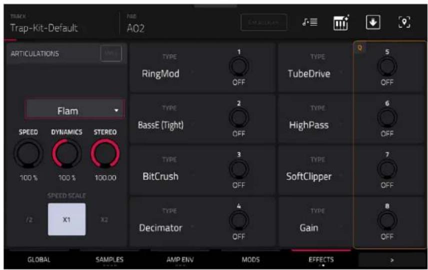
The Articulations section lets you apply variable drum articulations and rudiments like flams, paradiddles, and other dynamic phrases.
Tap the MPCe button to enable MPCe articulation control. This allows you to assign up to four different articulations to the four corners of a pad for dynamic articulation switching. When enabled, tap the 1–4 buttons below to select each pad quadrant. MPCe values can be input as automation for a pad.
Tap the dropdown menu to select the type of articulation applied to the pad or pad quadrant. Articulations are grouped into eight categories: Default Articulations, Standard Rudiments, Dotted Rudiments, Triplet Rudiments, Rolls, Pitched Rolls, Metric Rudiments, and Note Repeats.
Use the Speed knob to adjust the length of the articulation (25–400%). You can also use the Speed Scale /2, x1, and x2 buttons to quickly modify the set articulation speed.
Use the Dynamics knob to apply velocity modulation to the articulation (0–200%).
Use the Stereo knob to adjust the stereo spread of the articulation (0–100%).
The Drum FX section lets you add and control up to eight additional, simplified effects per pad in a Drum track.
Use the Type dropdown menu to select the effect in each slot:
- Ring Mod
- High Pass
- Bit Crush
- Rectifier
- Decimator
• Bass Enhancer (Tight) - Tube Drive
• Bass Enhancer (Medium) - Soft Clipper
• Bass Enhancer (Wide) - Hard Clipper
- Wave Folder
- Low Pass
- Gain
Use each knob to adjust the selected effect parameter.
LFO
Tap LFO to cycle between the LFO 1 and LFO 2 controls. You can also tap the LFO 1 and LFO 2 headers to toggle between them.
A low-frequency oscillator (LFO) generates a periodic waveform with an adjustable frequency and shape which can be used for modulation purposes.
![Track Trap-Kit-Default FAD AO2 LFO 1 WW LFO 2 WW DESTINATIONS WAVE Sine RESET On FADE IN FADE IN [SYNC] DELAY DELAY [SYNC] RATE RATE [SYNC] LEVEL 1.0 ms None 1.0 ms None 2.00 Hz None 127 M O D S E F F C T S LFO 1 U T I L I T I E S MOD MATRIX](/content/2026/05/883354/images/6bbfdc89a0e6cba19df269fa250710ac902cbfce736af9fc383c65ab346b6a7d.jpg)
Use the Wave field to select the LFO waveform type:
• Sine: Best suited for smooth modulations.
• Tri (Triangle): Best suited for smooth modulations.
• S&H: Samples a random value and holds it until the next value is generated.
- Saw: Can generate interesting filter or volume changes.
- SawD (Saw Down): Can generate interesting filter or volume changes.
• Sqr (Square): Interesting results with hard-panning modulations.
• Noise: Generates random values and glides.
Use the Reset field to determine whether the LFO retriggers on each note played (On) or not (Off).
Use the Fade In knob to set the length of time for the LFO to reach full level once triggered.
Use Fade In [Sync] to synchronize the fade in with the tempo. You can select one of several time divisions (a . indicates a dotted note; a T indicates a triplet-based time division). When None is selected, Sync is off, and the fade in length is determined by the Fade In knob.
Use the Delay knob to set the length of time between when the note is triggered and when the LFO is triggered.
Use Delay [Sync] to synchronize the delay time with the tempo. You can select one of several time divisions (a . indicates a dotted note; a T indicates a triplet-based time division). When None is selected, Sync is off, and the delay length is determined by the Fade In knob.
Use the Rate knob to determine the LFO frequency. At lower values, it might take some time for the LFO to complete a cycle, while higher values will come closer to audible range.
Use Rate [Sync] to synchronize the LFO's rate with the tempo. You can select one of several time divisions (a . indicates a dotted note; a T indicates a triplet-based time division). When None is selected, Sync is off, and the frequency is determined by the Rate knob.
Use the Level knob to set the overall amount of modulation applied by the LFO. At lower values, the modulation is more subtle, and at higher values it is more extreme.
Tap the Destinations → button in the LFO window to display the Destinations sliders. Use these sliders to determine how much the LFO affects the pitch of the sound (Pitch), the cutoff frequency of the filter (Filter), the volume level of the sound (Amp) and panning of the sound (Pan).
Utilities
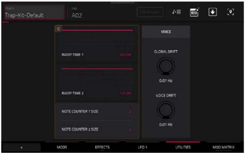
Use the Ramp Time 1/2 fields to adjust the ramp length. These can be used to apply additional modulation shaping to other parameters via the Mod Matrix.
Use the Note Counter 1/2 Size fields to set stepped modulation values. These can be used as part of the Mod Matrix to change parameter values based on the number of voices selected (2–64).
The Voice section allows you to add additional free running LFOs which can be used for subtle modulations in the Mod Matrix. Use the Global Drift knob to set the amount of drift applied to the entire drum track, or use the Voice Drift knob to set the amount of drift applied to the selected pad.
Mod Matrix
Tap the Mod Matrix tab to cycle through its eight available tabs. Alternatively, tap the numbered headers below the toolbar to select that tab.
The 32 available modulation points can be configured to add a wide variety of sound shaping tools.
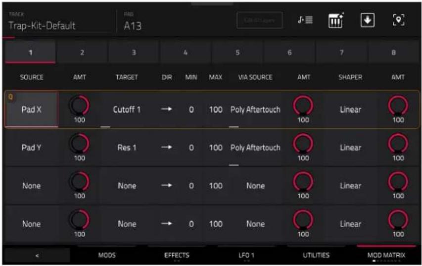
Use the Source field to select the modulation source.
Use the first Amt (Amount) field to set how much modulation is applied by the source.
Use the Target field to select the output target for modulation.
Use the Direction field to set whether the modulation direction is bipolar or unipolar.
Use the Min and Max fields to set the minimum and maximum modulation levels of the selected target.
Use the Via Source field to add a secondary modulation shaper using another source.
Use the second Amt (Amount) field to set how much modulation is applied by the secondary source.
Use the Shaper field to apply an additional modifier that affects the modulation relationship between the source and target.
Use the third Amt (Amount) field to set how much modulation is applied by the shaper.
Keygroup Tracks
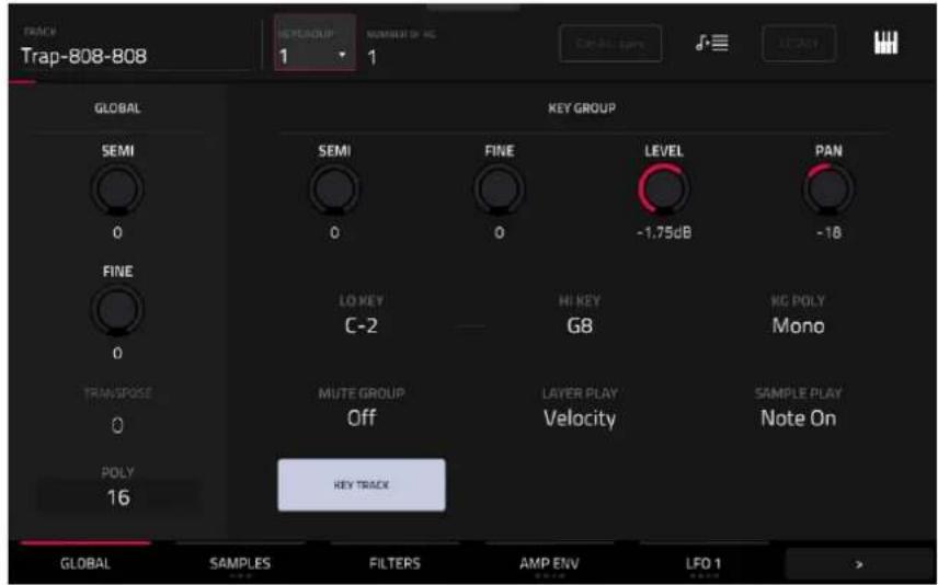
When using keygroup tracks, Track Edit Mode lets you edit the parameters for each keygroup.
Tap the Legacy button to enable or disable the Legacy Keygroup editing functions. When this button is enabled, keygroup editing functions the same as it has in previous MPC release. When this button is disabled, the new Advanced keygroup synthesis engine is enabled. Legacy mode is disabled by default. The following sections are labeled as being available in Advanced Mode, Legacy mode, or both Advanced and Legacy modes.
Press a pad or key to select its keygroup. Its parameters will appear on the screen immediately. Alternatively, use the Keygroup field at the top of the screen.
Tap the tabs at the bottom of the screen to view its specific parameters, such as Global or Samples. For tabs with multiple pages, tap the buttons multiple times to cycle through the available parameters.
Tap the Keygroup field to select a keygroup to edit. You can also select All to edit all keygroups simultaneously.
Number of KG (keygroups) lets you create up to 128 keygroups within a keygroup track. This is useful when working with multi-samples. For example, if you want to create a realistic piano, you can use different keygroups (e.g., 88 for a grand piano) with every keygroup containing its own sampled note (with up to four possible velocity layers).
Tap the Edit All Layers button to enable or disable editing control of all sample layers at the same time. When this is enabled, edits made to sample parameters such as Start/End points or Semi/Fine tuning on any one layer are automatically applied uniformly to all eight layers at once (even if some layers are empty).
Tap the Stems icon to open the Create Stems Function in the Process Sample window. You can use this process to isolate different parts of the sample and separate them into new stem samples.

Click the icons to select or deselect from the following elements to create stems of:
• Vocals: Isolate vocal elements of the track into a stem.
- Bass: Isolate bass elements of the track into a stem.
- Drums: Isolate percussive elements of the track into a stem.
- Other: Isolate other musical textures, such as keys or guitars, into a stem.

Use the Track dropdown menu to select the track where the stems will be added.
The Assign to Pad function determines where the stem separated samples are added. When checked, you can select a pad in the chosen Track using the dropdown menu, and the stems will be added to the first four layers of that pad. When unchecked, the stems will be added to the general project sample pool in the Project Info Browser.
Tap the Use trimmed sample box to trim the source sample between the Start and End points before applying the stem separation process.
Note: To purchase MPC Stems, visit akaipro.com/stems, and then activate your purchase in the Menu > Preferences > Activate Plugins menu.
Tap the piano-keys icon to edit the note range of the current keygroup. This will open the Set Keygroup Note Range window. This lets you restrict the key range used for a sample's playback. Only notes with a key number higher or equal (Low Key) or lower and equal (High Key) to the selected value will trigger a sound.
Tips:
Alternatively, you can set the current keygroup's note range by using the Lo and Hi fields under Note Range in the Global tab.
Set the Lo parameter to A0 and the Hi parameter to C8 to emulate the range of a standard 88-key piano.
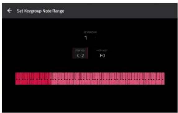
Global (Advanced and Legacy)
In the Global tab, you can set the playback mode and tuning for the overall track. This tab has the same features and functions in both Legacy and Advanced editing.

Global Semi lets you tune the track up to 36 semitones up or down.
Global Fine provides fine-tuning of the track up to 99 cents up or down.
Transpose shifts the pitch of the MIDI notes sent to the track up to 36 semitones up or down.
Poly (polyphony) sets the playback mode for the track's keygroups. In Mono Mode, only one keygroup will sound at a time. If a keygroup is played while another (or the same one) is still playing its sample/samples, the new keygroup will immediately mute all other currently playing keygroups in that track. In Poly Mode, several keygroups can be triggered at the same time (limited only by the total number of voices available).
The Key Group Semi field lets you transpose the sample 36 semitones up or down, while Fine provides fine-tuning of each layer up to 99 cents up or down.
Tip: The Edit Layers section has some parameters similar to those in this section (Level, Pan, Semi, Fine, Note Range). Remember that Key Group parameters control the overall settings for the sample, while Edit Layer parameters control the settings for each layer (up to 4).
Key Group Level controls the overall volume level of the loaded sample/samples.
Key Group Pan controls the overall panning of the loaded sample/samples in the stereo field.
The Lo Key and Hi Key fields let you restrict the key range used for a sample's playback. Only notes with a key number higher or equal (Lo) or lower and equal (Hi) to the selected value will trigger a sound. The settings for Lo and Hi are also shown in the virtual keyboard in the Edit Layers section. Alternatively, tap the piano-keys icon to open the Set Keygroup Note Range window.
Tip: Set the Lo parameter to A0 and the Hi parameter to C8 to emulate the range of a standard 88-key piano.

Use the KG Polyphony (keygroup polyphony) field to determine how the keygroup will play. When set to Mono, only one pad will sound at a time. If a pad is played while another (or the same one) is still playing its sample/samples, the new pad will immediately mute all other currently playing pads in that track. When set to Poly, several pads can be triggered at the same time, limited only by the total number of voices available. You can also select a specific number of pads (2–32) so that you can play up to this many pads at the same time (unless they exceed the total number of voices available).
Use the Mute Group field to assign the selected keygroup to one of the 32 available mute groups. When keygroups assigned to the same mute group receive MIDI notes, the last keygroup played will silence all other keygroups in that mute group. A mute group affects keygroups within that track only; mute groups do not affect keygroups in other tracks.
Key Track allows you to switch a sample's automatic transposition on or off. If this is off, you will always hear the same pitch of the sample, no matter which note is triggered by pads or a connected MIDI keyboard.
Layer Play determines how multiple samples assigned to the same pad are played:
- Cycle (Cyc): Each time the pad is played, it will play the next layer's sample. In other words, the samples will cycle through the layers as follows: 1, 2, 3, 4, 1, 2, 3, 4... etc.
• Velocity (Vel): The pad will switch between layers depending on how hard you press a pad. - Random (Ran): Each time the pad is played, it will play one of its layer's samples at random. When selected, the Random Seed field displays a value between 1–999,999. You can copy and reuse this value to reproduce the same random sequence.
- Crossfade: Crossfade between sample layers using modulation sources like envelopes and LFOs in the Mod Matrix, allowing for wave sequencing or vector synthesis-like effects.
Sample Play determines how much of the sample is played:
• One Shot: The entire sample will play from start to end. Use this when you want to play short sounds.
• Note Off: The entire sample will play from start to end after the pad has been pressed and released.
- Note On: The sample will play only as long as the pad is held. This is better for longer samples so you can control a sound's duration by pressing and holding its corresponding pad.
Samples (Advanced and Legacy)
Each keygroup can trigger up to four samples, which are assigned in four individual layers. Each layer has identical, independently assignable parameters.
Tap Samples to cycle through its available tabs. The first three tabs have identical features and functions in both Legacy and Advanced editing. Legacy features a fourth tab (Random), which is a separate tab in Advanced mode (see Randomize (Advanced)).

You can access the Settings window, which lets you configure certain settings in the Samples tab, from any of the three tabs by tapping the gear icon.
Use the Link Slices selector to set how the start point and end point of a slice in a larger sample is set. You can create these slices in Sample Edit Mode > Chop Mode.
When on, changing the start point of a slice will also change the end point of the previous slice. Similarly, changing the end point of a slice will also change the start point of the next slice. Disable Link Slices if you are trying to create slices that use non-contiguous parts of the sample. This is the same as the Link Slices button in Sample Edit Mode.
Use the Loop Lock selector to "link" or "unlink" the loop point from the start point. When on, the loop point is the same as the start point. When off, the loop point is independent from the start point and indicated by a separate loop marker. This is the same as the Loop Lock button in Sample Edit Mode.
Use the Zero Snap selector to enable or disable the Zero Snap feature, which forces start points, end points, and loop points to occur only at the waveform's "zero-crossings." This can help to avoid clicks and glitches when playing a sample. This is the same as the 0 Snap button in Sample Edit Mode.
Tap Close, the X in the upper-right corner, or anywhere outside the window to close the Settings window.
The first Samples tab contains the sample waveform for each layer and controls for its pitch, timing, and playback.

The upper half of the screen shows the waveform of the sample on the currently selected layer. The lower half shows the editing controls.
The waveform display shows the "active" section of the sample waveform. Swipe left or right on the waveform to move through it.
Above the waveform is the timeline, shown in bars, beats, and ticks.
Tap each layer number (Layer 1–8) under the waveform to select it. When selected, its sample waveform will be shown in the upper half of the screen and its settings will be shown in the lower half.
Use the Sample field to select the sample file for that layer. Remember that the sample has to be loaded into the project's sample pool beforehand. For information on how to load samples into a project, please see the Browser chapter.
Important: The parameters in the Samples tabs work in conjunction with Chop Mode (in Sample Edit Mode). Here's how it works:
When working in Sample Edit Mode and using Chop Mode to divide a sample into slices for your pads (keygroups), you can convert a slice using Non-Destructive Slice or Pad Parameters.
A Non-Destructive Slice will let its keygroup to refer to that slice when you press a pad in that keygroup; the original sample remains intact, and each slice marker is like a “bookmark” for a keygroup. In Track Edit Mode, you’ll see that the layer to which it’s assigned has its Slice drop-down menu set to the corresponding slice number in the original sample. Playing that keygroup will cause it to refer to that slice marker like a “bookmark” instead of creating an entirely new sample of that slice. This means that you no longer have to clutter your project with a new sample for every slice (though you can still use this earlier method, if you prefer).
A slice converted using Pad Parameters is very similar to a non-destructive slice described above. The difference is that in Track Edit Mode, the layers they're assigned to have their Slice drop-down menus set to Pad (instead of the slice number), and the start and end points will correspond to the slice markers in the original sample.
Tap the trash can icon next to the sample field to remove the file from the layer.

The green/S marker and red/E marker are the start point and end point (respectively). These two points define the region of the sample that will be played.
To move the start point or end point, do any of the following:
- Tap and drag the S or E marker left or right.
• Use the Start or End fields shown below the waveform.
- When the Q-Links are set to screen mode, you can use them to adjust the start and end points in fine and coarse adjustments. For MPC hardware with four Q-Links, the first bank adjusts the start point, and the second bank adjusts the end point.
Note: When Loop Lock is on, the loop position (as determined by the Loop field, if enabled) is the same as the sample's start point. When off, the loop position is independent from the start point.
Use the Loop field to determine the position where the sample's playback will repeat when Pad Loop is activated.
Note: When Loop Lock is on, the loop position is the same as the sample's start point. When off, the loop position is independent from the start point.
Use the Tail Length and Tail Start fields to add extra audio tail to any chopped sample. This is useful for things like making an abrupt end to a sample sound more natural or adding experimental looping effects to a sample. The Tail Length parameter enables the sample tail and set its total length, and the Tail Start parameter sets the starting point within the tail for looping.
Use the Repeats field to set a sample to play a specified number of times. First make sure Pad Loop is set to On, then use this field to set the number of times you want to have the sample loop between the Sample Loop and End points. For example, a value of 4 would repeat the selected area of the sample 4 times.
Note: The behavior difference between Repeats set to 0 and 1 is only evident when a Pad's Sample Play parameter is set to Note On. Then, when hold a note, a Repeat value of 0 will create infinite repeats, and a value of 1 will play a sample one time through.

Use the Slice field to select what part/parts of the sample will play:
• All: The entire sample will play.
- Pad: The sample will play from the Pad Start position to the Pad End position, described earlier. This also lets you activate Pad Loop (if the Sample Play field in the Global tab is set to Note On).
- Slice 1, 2, 3, etc.: If you have sliced the sample in Chop Mode, you can select which slice will play when you trigger the pad.
When Slice is selected, you can tap the Slice Motion icon to trigger a different sample slice each time a pad is played.
Use the Motion setting to select Increment, which increments the slice number with each new note event, or Random, which plays your slices in a random order.
Use the Slice field to set the starting slice.
Use the Cycles field to select how many of the slices are played.

Tap the pad repeatedly, or turn Note Repeat on and hold the pad, to hear the slices of your chopped loop play.
Use the Play Offset field to shift a sample window between the Start, End, and Loop points across the sample without altering their relative positions. For example, if you set these points to frame the first 1/16th note of a one-bar sample, you can use the Play Offset to shift that window to different 1/16th note positions within the sample. You must retrigger the sample to hear offset changes.
Use the Reverse button to select in which direction the sample will play. When on, the sample will play in reverse. When off, the sample will play in the normal forward direction.

Use the Pad Loop button to cycle through the available Pad Loop modes.
Important: For Pad Loop to work, you must (1) set the Sample Play field (in the Global tab) to Note On instead of One Shot and (2) set the Slice field (in the first Samples tab) to Pad instead of All or a slice number.
• Off: The sample will not loop.
- Forward: You can hold down the pad to cause that sample to repeat from the Loop Position to the end of the sample. Release the pad to stop the repeating playback.
- Reverse: You can hold down the pad to cause that sample to play in reverse, repeating from the end of the sample to the Loop Position. Release the pad to stop the repeating playback.
- Alternating: You can hold down the pad to cause that sample to play from the Loop Position to the end of the sample and then play in reverse until it reaches the Loop Position again. This will repeat as long as you are holding the pad down. Release the pad to stop the repeating playback.

Semi lets you transpose the selected layer up to 36 semitones up or down. This is the same as the Semi knob on the second Samples tab.
Fine provides fine-tuning of each layer by cents. This is the same as the Fine knob on the second Samples tab.
The second Samples tab (Tune/Mix) contains controls for its pitch, volume level, and panning.

Tap the Layer 1-4/Layer 5-8 button to toggle between visible layers.
Use the Sample field to select the sample file for that layer. Tap the trash can icon next to the sample field to remove the file from the layer.
Semi lets you transpose the selected layer up to 36 semitones up or down. This will affect the length of the sample (if Warp is off). This is the same as the Semi field on the first Samples tab.
Fine provides fine-tuning of each layer by cents. This will affect the length of the sample (if Warp is off). This is the same as the Fine field on the first Samples tab.
Level lets you adjust each layer's volume, letting you control the "balance" of the samples assigned to the pad.
Pan lets you adjust the stereo placement of the respective layer.
The third Samples tab (Velocity) contains the control for its offset, velocity range, and root note.

Tap the Layer 1-4/Layer 5-8 button to toggle between visible layers.
Use the Sample field to select the sample file for that layer. Tap the trash can icon next to the sample field to remove the file from the layer.
Use the Offset slider to determine a time offset for the sample's playback.
- Positive values (right of center): When the pad is played, playback will start immediately but at a later point in the sample specified by the offset value.
- Negative values (left of center): When the pad is played, playback will be delayed by the amount specified by the offset value.
Use the Vel Start and Vel End knobs to define the velocity range of each layer.
A range from 0 to 127 lets the layer respond to the entire velocity range which is input from the respective pad while, for example, a range from 100 to 127 lets the layer respond only to higher velocity levels. By assigning several samples of one instrument, you can create a realistic-sounding “multi-sample” by adjusting the velocity ranges of each layer accordingly.
For example, you may have three samples of a piano key with low force, medium force, and high force. You can set each sample to a layer and set the Velocity ranges so only low velocities trigger the low-force sample, only mid-range velocities trigger the medium-force sample, and only high velocities trigger the high-force sample.
Use the Root Note menu to set the starting note of each loaded sample. Smp denotes the sample's default pitch.
The fourth Samples tab (Random) contains the controls for adding randomization to sample parameters such as pitch, level and panning.
Note: This tab is only available in Legacy mode. In Advanced mode, use the separate Randomize (Advanced) tab.
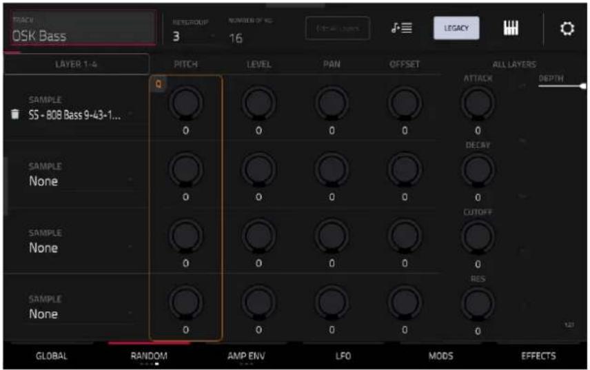
Tap the Layer 1-4/Layer 5-8 button to toggle between visible layers.
Use the Sample field to select the sample file for that layer. Tap the trash can icon next to the sample field to remove the file from the layer.
Use the Pitch knobs to adjust the amount of randomization applied to each sample layer's pitch.
Use the Level knobs to adjust the amount of randomization applied to each sample layer's volume.
Use the Pan knobs to adjust the amount of randomization applied to each sample layer's stereo placement.
Use the Offset knobs to adjust the amount of randomization applied to each sample layer's time offset.
The All Layers section will apply randomization to all sample layers for the following envelope parameters: Attack, Decay, Cutoff and Resonance. Use the Depth slider to control the amount of envelope randomization applied overall.
Filters (Advanced)
The Filters tab features two filters which can be run in either parallel or series configuration, with a blend control for mixing between them.

Use the Filter 1/2 Type fields to select each filter for the selected keygroup. See Appendix > Glossary > Filter for an explanation of the available filter types.
Use the Cutoff knob to set the cutoff frequency for low-pass and high-pass filter types or the center frequency for band-pass and band-stop filter types.
Use the Resonance knob to set the resonance/emphasis of the frequencies around the cutoff point.
Tip: Use values lower than 80 to give more brilliance to the sound. At values higher than 80, the sound will result in a strong audible boost around the cutoff frequency.
Use the Output knob to set the output level of the filter.
Use the Env knob to set the amount of effect the Filter Envelope has on the Cutoff frequency.
Use the Keytrack knob to adjust how the filter cutoff is tied to the pitch being played. At higher levels, the amount of cutoff reduction is more noticeable as the pitch is raised.
Tap the Filt Env icon to open the Filter Envelope. This is the same Filter Envelope that can be adjusted in the Envelopes (Advanced) section. Adjusting in either view will automatically update the other view. Tap the minimize icon to close the expanded filter window.
Use the Blend knob to adjust the mix between the two filters.
Use the Parallel/Serial button to toggle whether the filters run side-by-side (Parallel) or one into the other (Serial).
Tap the Velocity → button to access the Velocity Sensitivity control for each filter. These modulation controls determine how much the velocity affects the cutoff frequency of the filter envelope (Cutoff), and depth of influence the filter envelope has on the cutoff frequency (Depth).
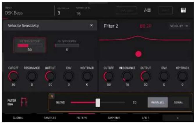
Envelopes (Advanced)
Tap the Advanced Envelopes tab to cycle through its four available tabs. Alternatively, tap the filter headers below the toolbar to select that tab: Amp, Filter, Pitch, and Aux.
The first Advanced Envelope tab contains the amplitude modulation envelope.

Use the Looped field to enable or disable looping of the envelope. When set to On, the envelope will restart once it has reached its end. The length of the envelope is determined by the Tempo Sync value, or the total envelope length, as set by the Delay, Attack, Hold, Decay, Sustain, and Release knobs. When set to Off, the envelope triggers on each note-on only.
Use the Tempo Sync field to synchronize the envelope loop with the tempo. You can select one of several time divisions (a . indicates a dotted note; a T indicates a triplet-based time division). When None is selected, Sync is off, and the loop length is determined by the total length of the Delay, Attack, Hold, Decay, Sustain, and Release settings.
Use the Time Scaling field to apply an additional time adjustment to the loop length. At 100%, the total loop length is unchanged. The loop length is shorted when set to below 100%, and lengthened when set to above 100%.
Use the Global field to determine whether the envelope is applied to only the current voice (Off) or to the entire keygroup (On).
The Amp Envelope controls affect level changes over time. Use the Delay, Attack, Hold, Decay, Sustain, and Release fields or tap and drag the “handles” of the envelope to shape the envelope or time-variant modulation output. Adjust the envelope’s influence on the filter frequency with the Env knob. See the later Anatomy of an Envelope section to learn about the envelope parameters.

Keygroup Level controls the overall volume level of the loaded sample/samples.
Keygroup Pan controls the overall panning of the loaded sample/samples in the stereo field.
Tap the Keygroup → button to access the Velocity To controls. These modulation controls determine how much the velocity affects the attack of the amplitude envelope (Amp Attack), the volume level of the amplitude envelope (Amp), and/or the panning of the sound (Pan).
When you press a pad softly, only minimal modulation is applied. When you press it harder, the modulation amount also gets stronger depending on the setting of the corresponding slider.
Tap the X to exit the Velocity To controls.
The second Advanced Envelope tab contains the filter modulation envelope.

Use the Looped field to enable or disable looping of the envelope. When set to On, the envelope will restart once it has reached its end. The length of the envelope is determined by the Tempo Sync value, or the total envelope length, as set by the Delay, Attack, Hold, Decay, Sustain, and Release knobs. When set to Off, the envelope triggers on each note-on only.
Use the Tempo Sync field to synchronize the envelope loop with the tempo. You can select one of several time divisions (a . indicates a dotted note; a T indicates a triplet-based time division). When None is selected, Sync is off, and the loop length is determined by the total length of the Delay, Attack, Hold, Decay, Sustain, and Release settings.
Use the Time Scaling field to apply an additional time adjustment to the loop length. At 100%, the total loop length is unchanged. The loop length is shorted when set to below 100%, and lengthened when set to above 100%.
Use the Global field to determine whether the envelope is applied to only the current voice (Off) or to the entire keygroup (On).
The Filter Envelope controls affect the filter frequency. Use the Delay, Attack, Hold, Decay, Sustain, and Release fields or tap and drag the "handles" of the envelope to shape the envelope or time-variant modulation output. Adjust the envelope's influence on the filter frequency with the Depth knob. See the later Anatomy of an Envelope section to learn about the envelope parameters.
Use the Env knobs to determine the amount of influence the filter envelope has on the cutoff frequency. Higher settings will increase the modulation of the filter by the envelope; lower settings will result in only subtle changes of the filter Cutoff over time.
Tip: To give a sound a more distinctive attack, increase the Env setting and set low Atk and Decay values as well as a medium-low Sust value of the Filter Envelope. This will start a sound with the filter opened and close it shortly afterward, giving it a bright start followed by a darker sustain. String sounds, on the other hand, can sound much more “alive” with low Depth settings and a high Atk value, resulting in a slight fade-in of the higher frequencies.

Use the Type field to select up to two filter types for the selected keygroup. These are the same filters as set in the Filters (Advanced) tab. See Appendix > Glossary > Filter for an explanation of the available filter types.
Use the Cutoff knob to set the cutoff frequency for low-pass and high-pass filter types or the center frequency for band-pass and band-stop filter types.
Tap the Filter → button to access the Velocity To controls. These modulation controls determine how much the velocity affects the attack phase of the filter envelope (Attack), the cutoff frequency of the filter envelope (Filter 1/2 Cut), and/or depth of influence the filter envelope has on the cutoff frequency (Filter 1/2 Env).
When you press a pad softly, only minimal modulation is applied. When you press it harder, the modulation amount also gets stronger depending on the setting of the corresponding slider.
Tap the X to exit the Velocity To controls.

The third Advanced Envelope tab contains the pitch modulation envelope.

Use the Looped field to enable or disable looping of the envelope. When set to On, the envelope will restart once it has reached its end. The length of the envelope is determined by the Tempo Sync value, or the total envelope length, as set by the Delay, Attack, Hold, Decay, Sustain, and Release knobs. When set to Off, the envelope triggers on each note-on only.
Use the Tempo Sync field to synchronize the envelope loop with the tempo. You can select one of several time divisions (a . indicates a dotted note; a T indicates a triplet-based time division). When None is selected, Sync is off, and the loop length is determined by the total length of the Delay, Attack, Hold, Decay, Sustain, and Release settings.
Use the Time Scaling field to apply an additional time adjustment to the loop length. At 100%, the total loop length is unchanged. The loop length is shorted when set to below 100%, and lengthened when set to above 100%.
Use the Global field to determine whether the envelope is applied to only the current voice (Off) or to the entire keygroup (On).
The Pitch Envelope controls affect the keygroups's pitch change over time. Use the Delay, Attack, Hold, Decay, Sustain, and Release fields or tap and drag the "handles" of the envelope to shape the envelope or time-variant modulation output.
Adjust the envelope's influence on the pitch with the Env Depth knob. See the later Anatomy of an Envelope section to learn about the envelope parameters.

Global Semi lets you transpose the keygroup up to 36 semitones up or down. This will affect the length of the sample (if Warp is off). This is the same as the Semi field on the Global tab.
Global Fine provides fine-tuning of each layer by cents. This will affect the length of the sample (if Warp is off). This is the same as the Fine field on the Global tab.
Tap the Filter → button to access the Velocity To controls. This modulation control determines how much the velocity affects the pitch envelope (Pitch).
When you press a pad softly, only minimal modulation is applied. When you press it harder, the modulation amount also gets stronger depending on the setting of the Pitch slider.
Tap the X to exit the Velocity To controls.
The fourth Advanced Envelope tab contains the aux modulation envelope. This can be used as part of the Modulation matrix to apply an envelope to other parameters.

Use the Looped field to enable or disable looping of the envelope. When set to On, the envelope will restart once it has reached its end. The length of the envelope is determined by the Tempo Sync value, or the total envelope length, as set by the Delay, Attack, Hold, Decay, Sustain, and Release knobs. When set to Off, the envelope triggers on each note-on only.
Use the Tempo Sync field to synchronize the envelope loop with the tempo. You can select one of several time divisions (a . indicates a dotted note; a T indicates a triplet-based time division). When None is selected, Sync is off, and the loop length is determined by the total length of the Delay, Attack, Hold, Decay, Sustain, and Release settings.
Use the Time Scaling field to apply an additional time adjustment to the loop length. At 100%, the total loop length is unchanged. The loop length is shorted when set to below 100%, and lengthened when set to above 100%.
Use the Global field to determine whether the envelope is applied to only the current voice (Off) or to the entire keygroup (On).
The Aux Envelope controls adjust the shape of the envelope, which can be used to apply envelope shaping to other parameters in the Modulation Matrix. Use the Delay, Attack, Hold, Decay, Sustain, and Release fields or tap and drag the "handles" of the envelope to shape the envelope or time-variant modulation output.
LFO (Advanced)
Tap the Advanced LFO tab to cycle through its four available tabs. Alternatively, tap the filter headers below the toolbar to select that tab: LFO 1, LFO 2, Global LFO 1, and Global LFO 2.
A low-frequency oscillator (LFO) generates a periodic waveform with an adjustable frequency and shape which can be used for modulation purposes. There are two per-voice LFOs and two global LFOs for extensive modulation options.
The first and second Advanced LFO tabs contain the per-voice LFOs.

Use the Wave field to select the LFO waveform type:
• Sine: Best suited for smooth modulations.
• Tri (Triangle): Best suited for smooth modulations.
• S&H: Samples a random value and holds it until the next value is generated.
- Saw: Can generate interesting filter or volume changes.
- SawD (Saw Down): Can generate interesting filter or volume changes.
- Sqr (Square): Interesting results with hard-panning modulations.
• Noise: Generates random values and glides.
Use the Fade In field to set the length of time for the LFO to reach full level once triggered.
Use the Fade In [Sync] to synchronize the fade in with the tempo. You can select one of several time divisions (a . indicates a dotted note; a T indicates a triplet-based time division). When None is selected, Sync is off, and the fade in length is determined by the Fade In knob.
Use the Reset field to determine whether the LFO retriggers on each note played (On) or not (Off).

Use the Delay knob to set the length of time between when the note is triggered and when the LFO is triggered.
Use the Delay [Sync] to synchronize the delay time with the tempo. You can select one of several time divisions (a . indicates a dotted note; a T indicates a triplet-based time division). When None is selected, Sync is off, and the delay length is determined by the Fade In knob.
Use the Rate knob to determine the LFO frequency. At lower values, it might take some time for the LFO to complete a cycle, while higher values will come closer to audible range.
Use the Rate [Sync] knob to set if the LFO's rate when synchronized with the tempo. You can select one of several time divisions (a . indicates a dotted note; a T indicates a triplet-based time division). When None is selected, Sync is off, and the frequency is determined by the rate knob.
Use the Level knob to set the overall amount of modulation applied by the LFO. At lower values, the modulation is more subtle, and at higher values it is more extreme.
Use the Wheel to LFO knob to adjust how much control mod wheel data (MIDI CC1) has over the LFO. When set to 0, the mod wheel has no effect on the LFO level. When set to 100, the LFO is fully controlled by the mod wheel.

Tap the Destinations → button to access the destination controls. These sliders to determine how much the LFO affects the pitch of the sound (To Pitch), the cutoff frequency of the filter (To Filter 1/2), the volume level of the sound (To Amp) and panning of the sound (To Pan).
The third and fourth Advanced LFO tabs contain the Global LFOs.
![TRACK OSK Bass REFERENCE 3 16 LFO 1 WW LFO 2 WW GLOBAL LFO 1 WW GLOBAL LFO 2 WW WAVE Side RATE RATE [SYNC] LEVEL 2.00 Hz None 127 GLOBAL SAMPLES FILTERS AMP ENV GLOBAL LFO 1 >](/content/2026/05/883354/images/df6b644a397d6f57d2bee80a254d0268df272c23999613a8c885eb4a007818ab.jpg)
Use the Wave field to select the LFO waveform type:
• Sine: Best suited for smooth modulations.
• Tri (Triangle): Best suited for smooth modulations.
• S&H: Samples a random value and holds it until the next value is generated.
- Saw: Can generate interesting filter or volume changes.
- SawD (Saw Down): Can generate interesting filter or volume changes.
• Sqr (Square): Interesting results with hard-panning modulations.
• Noise: Generates random values and glides.
Use the Rate knob to determine the LFO frequency. At lower values, it might take some time for the LFO to complete a cycle, while higher values will come closer to audible range.
Use the Rate [Sync] knob to set if the LFO's rate when synchronized with the tempo. You can select one of several time divisions (a . indicates a dotted note; a T indicates a triplet-based time division). When None is selected, Sync is off, and the frequency is determined by the rate knob.
Use the Level knob to set the overall amount of modulation applied by the LFO. At lower values, the modulation is more subtle, and at higher values it is more extreme.
Utilities/Sensitivity (Advanced)
Tap the Advanced Utilities/Sensitivity tab to cycle through the two tabs.
The Utilities tab contains additional modulation parameters, as well as portamento and pitch bend controls.

Use the Ramp Time 1/2 fields to adjust the ramp length. These can be used to apply additional modulation shaping to other parameters via the Mod Matrix.
Use the Note Counter 1/2 Size fields to set stepped modulation values. These can be used as part of the Mod Matrix to change parameter values based on the number of voices selected (2–64).
Use the Global Drift knob to set the amount of pitch drift applied to the entire keygroup.
Use the Voice Drift knob to set the amount of pitch drift applied to the selected keygroup voice.
Use the Timbre Shift knob to adjust the amount of tonal character shaping applied to the keygroup.
Use the Portamento parameters to adjust the settings for pitch gliding.
The Time knob sets the length of the glide between notes.
Tap the Legato button to enable or disable pitch gliding for all triggered notes or just legato notes.
Tap the Mono Retrig button to allow the portamento to retrigger on every key press when using mono polyphony.
Tap the Quantize button to synchronize the portamento time with the project tempo.
Use the Pitch Bend fields to set the number of semitones shifted up or down when pitch bend is applied.
The Sensitivity tab contains settings for velocity sensitivity and external controller modulation.

Use the Velocity To sliders to set how much velocity is required to modulate certain other parameters:
• Filter 1/2 Cutoff uses the velocity of a pad to modulate the cutoff frequency directly.
- Amp Attack sets how much velocity is needed (for a triggered pad) to modulate the Attack phase for the Amp envelope.
- Filter 1/2 Env Depth enables velocity information to control the amount of the filter envelope's effect on the cutoff frequency.
- Filter Env Attack sets how much velocity is needed (for a triggered pad) to modulate the Attack phase for the Filter envelope.
- Amp enables velocity information to control the overall amplitude (level) of the sample.
- Pan enables velocity information to control the stereo panning of the sample.
- Pitch enables velocity information to control the pitch of the sample.
The Controller Mod section determines the influence of additional play controllers on various sound parameters.
Important: To use these parameters, make sure that a connected MIDI device can send pitch bend messages as well as aftertouch and modulation wheel data.
Aftertouch To Cut 1/2 determines how much a connected MIDI keyboard's aftertouch data affects the filter cutoff.
Pressure To Filter determines how much a connected MIDI device's channel pressure data affects the filter envelope.
KG Stack (Advanced)
Tap the Advanced KG Stack tab to cycle through its three available tabs. You must first enable a Keygroup Stack effect to show the selected controls: Unison or Harmonizer. Only one stack effect may be used at a time.
The first Advanced KG Stack tab contains the Unison controls.

Use the Voices knob to adjust the number of unison voices.
Use the Detune knob to adjust the amount of fine-tuning applied to the unison voices in cents.
Use the Stereo Spread knob to adjust the width of the unison voices in the left-right stereo field.
Use the type selector to select the type of unison voice stacking applied (Classic, Linear, Parabolic, or Random).
The second and third Advanced KG Stack tab contains the Harmonizer controls.


Tap the Note number to enable each harmonizer voice.
Use the Shift field to set the amount of pitch shifting applied to the voice in semitones.
Use the Detune knob to adjust the amount of detuning to the voice in cents.
Use the Volume knob to set the level of the voice.
Use the Pan knob to set the stereo panning of the voice.
Use the Vel Scale knob to adjust the ratio of the harmonized voice velocity with the incoming note velocity.
Use the Delay knob to add an additional time delay between the note start and the harmonized voice start.
Use the Sync knob to set the Delay time when synchronized with the tempo. You can select one of several time divisions (a . indicates a dotted note; a T indicates a triplet-based time division). When None is selected, Sync is off, and the delay time is determined by the Delay knob.
Use the Mix slider to set the overall wet/dry mix between the original note and the harmonized voices.
Mod Matrix (Advanced)
Tap the Advanced Mod Matrix tab to cycle through its eight available tabs. Alternatively, tap the numbered headers below the toolbar to select that tab.
The 32 available modulation points can be configured to add a wide variety of sound shaping tools.

Use the Source field to select the modulation source.
Use the first Amt (Amount) field to set how much modulation is applied by the source.
Use the Target field to select the output target for modulation.
Use the Direction field to set whether the modulation direction is bipolar or unipolar.
Use the Min and Max fields to set the minimum and maximum modulation levels of the selected target.
Use the Via Source field to add a secondary modulation shaper using another source.
Use the second Amt (Amount) field to set how much modulation is applied by the secondary source.
Use the Shaper field to apply an additional modifier that affects the modulation relationship between the source and target.
Use the third Amt (Amount) field to set how much modulation is applied by the shaper.
Randomize (Advanced)
Tap the Advanced Randomize tab to cycle through its two available tabs. On these tabs you can apply randomization to the eight keygroup layers, as well as to all layers globally. The first tab controls layer 1–4, and the second tab controls layers 5–8.

The All Layers section will apply randomization to all sample layers for the following envelope parameters: Attack, Decay, Cutoff 1/2, and Resonance 1/2.
Use the Pitch knobs to adjust the amount of randomization applied to each sample layer's pitch.
Use the Level knobs to adjust the amount of randomization applied to each sample layer's volume.
Use the Pan knobs to adjust the amount of randomization applied to each sample layer's stereo placement.
Use the Offset knobs to adjust the amount of randomization applied to each sample layer's time offset.
Use the Total Amount slider to control the depth of envelope randomization applied overall.
Envelopes (Legacy)
Tap Envelopes to cycle through its three available tabs.
The first Envelope tab contains the amplitude modulation envelope.
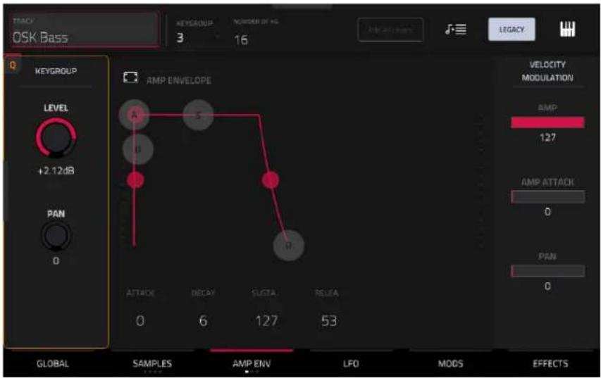
Keygroup Level controls the overall volume level of the loaded sample/samples.
Keygroup Pan controls the overall panning of the loaded sample/samples in the stereo field.
The Amp Envelope controls affect level changes over time. Use the fields or tap and drag the “handles” of the envelope to shape the envelope or time-variant modulation output. Adjust the envelope’s influence on the filter frequency with the Env knob. See the later Anatomy of an Envelope section to learn about the envelope parameters.
The Velocity Modulation controls determine how much the velocity affects the volume level of the amplitude envelope (Amp), the attack of the amplitude envelope (Amp Attack), and/or the panning of the sound (Pan).
When you press a pad softly, only minimal modulation is applied. When you press it harder, the modulation amount also gets stronger depending on the setting of the corresponding slider.
The second Envelope tab contains the filter modulation envelope.

Use the Type field to select a filter for the selected pad. See Appendix > Glossary > Filter for an explanation of the available filter types.
Use the Cutoff knob to set the cutoff frequency for low-pass and high-pass filter types or the center frequency for band-pass and band-stop filter types.
Use the Reso knob to set the resonance/emphasis of the frequencies around the cutoff point.
Tip: Use values lower than 80 to give more brilliance to the sound. At values higher than 80, the sound will result in a strong audible boost around the cutoff frequency.
The Filter Envelope controls affect the filter frequency. Use the fields or tap and drag the “handles” of the envelope to shape the envelope or time-variant modulation output. Adjust the envelope’s influence on the filter frequency with the Depth knob. See the later Anatomy of an Envelope section to learn about the envelope parameters.
Use the Depth slider to determine the amount of influence the filter envelope has on the cutoff frequency. Higher settings will increase the modulation of the filter by the envelope; lower settings will result in only subtle changes of the filter Cutoff over time.
Tip: To give a sound a more distinctive attack, increase the Depth setting and set low Atk and Decay values as well as a medium-low Sust value of the Filter Envelope. This will start a sound with the filter opened and close it shortly afterward, giving it a bright start followed by a darker sustain. String sounds, on the other hand, can sound much more “alive” with low Depth settings and a high Atk value, resulting in a slight fade-in of the higher frequencies.
The Velocity Modulation controls determine how much the velocity affects the cutoff frequency of the filter envelope (Cutoff), the attack phase of the filter envelope (Attack), and/or depth of influence the filter envelope has on the cutoff frequency (Depth).
When you press a pad softly, only minimal modulation is applied. When you press it harder, the modulation amount also gets stronger depending on the setting of the corresponding slider.
The third Envelope tab contains the pitch modulation envelope.

Global Semi lets you transpose the keygroup up to 36 semitones up or down. This will affect the length of the sample (if Warp is off). This is the same as the Semi field on the Global tab.
Global Fine provides fine-tuning of each layer by cents. This will affect the length of the sample (if Warp is off). This is the same as the Fine field on the Global tab.
The Pitch Envelope controls affect the keygroups's pitch change over time. Use the fields or tap and drag the "handles" of the envelope to shape the envelope or time-variant modulation output. Adjust the envelope's influence on the pitch with the Depth slider. See the later Anatomy of an Envelope section to learn about the envelope parameters.
The Velocity Modulation control determines how much the velocity affects the pitch envelope (Pitch).
When you press a pad softly, only minimal modulation is applied. When you press it harder, the modulation amount also gets stronger depending on the setting of the Pitch slider.
LFO (Legacy)

A low-frequency oscillator (LFO) generates a periodic waveform with an adjustable frequency and shape which can be used for modulation purposes.
Use the Waveform field to select the LFO waveform type:
• Sine: Best suited for smooth modulations.
• Tri (Triangle): Best suited for smooth modulations.
• S&H: Samples a random value and holds it until the next value is generated.
- Saw: Can generate interesting filter or volume changes.
- SawD (Saw Down): Can generate interesting filter or volume changes.
• Sqr (Square): Interesting results with hard-panning modulations.
• Noise: Generates random values and glides.
Use the Rate field to determine the LFO frequency. At lower values, it might take some time for the LFO to complete a cycle, while higher values will come closer to audible range.
Use the Sync field to set if the LFO's rate is synchronized with the tempo. You can select one of several time divisions (a . indicates a dotted note; a T indicates a triplet-based time division). When None is selected, Sync is off.
Use the Destinations sliders to determine how much the LFO affects the pitch of the sound (Pitch), the cutoff frequency of the filter (Filter), the volume level of the sound (Amp) and panning of the sound (Pan).
Mods (Legacy)
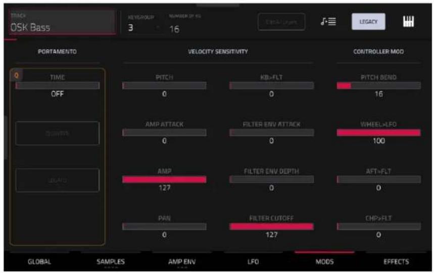
Use the Portamento fields to adjust the settings for pitch gliding.
The Time slider sets the length of the glide between notes.
Tap the Quantize button to synchronize the portamento time with the project tempo.
Tap the Legato button to enable or disable pitch gliding for all triggered notes or just legato notes.
Use the Velocity Sensitivity sliders to set how much velocity is required to modulate certain other parameters:
- Pitch enables velocity information to control the pitch of the sample.
- Amp Attack sets how much velocity is needed (for a triggered pad) to modulate the Attack phase for the Amp envelope.
- Amp enables velocity information to control the overall amplitude (level) of the sample.
- Pan enables velocity information to control the stereo panning of the sample.
- KB>FLT sets how much the note value will be added to the filter cutoff. This allows samples to sound brighter as they are played higher on the keyboard.
- Filter Env Attack sets how much velocity is needed (for a triggered pad) to modulate the Attack phase for the Filter envelope.
- Filter Env Depth enables velocity information to control the amount of the filter envelope's effect on the cutoff frequency.
• Filter Cutoff uses the velocity of a pad to modulate the cutoff frequency directly.
The Controller Mod section determines the influence of additional play controllers on various sound parameters.
Important: To use these parameters, make sure that a connected MIDI device can send pitch bend messages as well as aftertouch and modulation wheel data.
Pitch Bend sets the range (in semitones) of a connected MIDI keyboard's pitch-bend wheel.
Wheel>LFO determines how much a connected MIDI keyboard's modulation wheel affects the LFO intensity.
Aft>Filt (Aftertouch→Filter Cutoff) determines how much a connected MIDI keyboard's aftertouch data affects the filter cutoff.
Chp>Filt (Channel Pressure→Filter Cutoff) determines how much a connected MIDI keyboard's channel pressure data affects the filter cutoff.
Effects (Legacy)
![TRACK OSK Bass REVERGUL 3 16 LEGACY INSERTS ALL ON 1 AIR Para EQ [2 in 2 out] AIR Compressor [2 in 2 out] NO EFFECT NO EFFECT GLOBAL SAMPLES AMP ENV LFO MODS SEND 1 0 SEND 2 0 SEND 3 0 SEND 4 0 EFFECTS](/content/2026/05/883354/images/9fba61f5133f319b6baf0d790cb32799046c77efd71c7e5c9ed33763289e773b.jpg)
Inserts
You can select up to four insert effects for each keygroup. To learn how to use insert effects, please see General Features > Effects > Insert Effects.
Important: When using keygroup insert effects, they will be applied to that keygroup only. Keep this in mind if you load insert effects to multiple keygroups with overlapping note ranges—the effects will overlap in that range as well.
To add an effect:
- Double-tap the desired Inserts slot. A list of effects will appear.
- Swipe up or down to move through the list.
You can tap the Type and Manufacturer buttons to sort your effects by those categories.
- To load an effect, double-tap it, or tap Select.
To close the list, tap Close.
Tap the Akai folder icon to load a factory FX rack. You can choose from a number of preset combinations of insert effects by applications like Drums and Percussion, Voice, LoFi, Mastering, and more.
Tap second folder icon to load a saved FX rack.
Tap the disk icon to save an FX rack.
Tap the All On/Off button in the upper-right corner to enable or disable all four insert effects.
Tap the arrows next to the insert slot to move the selected effect up or down to rearrange an insert effect.
Tap the pencil icon to adjust the effect's parameters. Use the controls to set the value of each parameter. These values affect only this instance of the effect; insert effects are not global.
Tap the trash can icon to remove an effect from its slot.
Tap the On/Off button for the slot to enable or disable the effect.

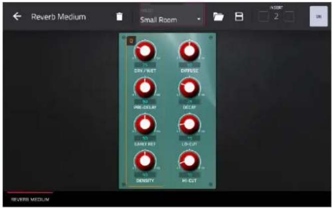
Tap the trash can icon to remove the effect from its slot.
Tap the folder icon next to the preset name at the top of the display to open the file browser and load an effect preset.
Tap the disk icon next to the insert selector at the top of the display to save a new effect preset.
Tap the -/+ buttons to rearrange the insert effect. Adjacent effects will be moved up or down in relation.
Tap the On/Off button to enable or disable the effect.
Sends
The audio of the track will be routed to send effects (if you have any loaded) at their designated send levels. The return channels will then send the audio to an assigned main output at the designated return levels.
Use the Send knobs to set the volume level of the signal the track will route to each send effect.
You can select up to four send effects for each keygroup, but remember that they will be applied to that keygroup only. Keep this in mind if you load insert effects to multiple keygroups with overlapping note ranges—the effects will overlap in that range as well.
Important: To use a send effect, you have to load an effect into the corresponding send effect slot in the mixer. See General Features > Effects > Send/Return Effects to learn more how to do this.
Plugin Tracks

For plugin tracks, you will see an overview of all available plugin parameters with a slider for each, or a visual representation of the plugin interface.
Use the sliders to set the value of each parameter, or use the plugin interface.
Use the tabs at the bottom of the screen to access the available parameters.
To load a plugin preset, tap the folder icon next to the preset name at the top of the display to open the file browser. To save a new plugin preset, tap the disk icon next to the insert selector at the top of the display.
MIDI Tracks

For MIDI tracks, you will see an overview of all available MIDI CCs with a slider for each.
Use the sliders to set the value of each parameter.
Use the six tabs at the bottom of the screen to access the available parameters.
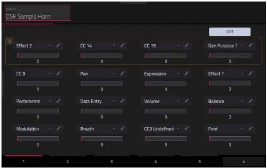
Tap the Edit button in the top-right of the page to edit the MIDI track assignments and naming.
To assign a parameter, tap the dropdown menu and use the data dial or +/- buttons to scroll through the available MIDI assignments. You can also double-tap the menu to view a list of assignments.
To rename a parameter, tap the pencil icon next to the dropdown menu, and then use the keyboard that appears to enter a new name. Once renamed, you can save the track and use it with other projects to retain your custom naming.
CV Tracks

For CV tracks, you will see an overview of all available CV outputs with a slider for each.
Use the sliders to set the value of each parameter.
Anatomy of an Envelope
An envelope creates a variable control signal. It can be used, for instance, to modulate the filter settings of a sound over a given period of time.
For drum tracks, use the AD/AHDS selector to select an AD or AHDS envelope. When Sample Play is set to Note-On, it will use an ADSR envelope.
Keygroup tracks always use AHDS envelopes. When Sample Play is set to Note-On, it will use an ADSR envelope.
With AHDS envelopes, the following happens when you trigger a sample:
- Within the period of time you have defined with the attack (Atk), the sample volume rises to its maximum value.
- The sample's maximum volume will be maintained during the Hold phase.
- During the Decay phase, the sample's volume will gradually drop to the sustain level.
- The sample's volume will stay at the sustain level (Sust) until the pad is released.
Use the A Shape and D Shape fields to adjust the curve of the Attack and Decay phases, respectively.

line
| Point | Value | |-------|-------| | A | 65 | | B | -25 | | C | 25% | | D | 81 | | E | 9 | | F | 103 |With AD envelopes, the following happens when you trigger a sample:
- Within the period of time you have defined with the attack (Atk), the sample volume rises to its maximum value.
-
The sample's maximum volume will be maintained until its Decay phase, when the sample's volume will gradually drop to zero over the set duration. Tap the Type drop-down menu to select how the decay functions:
-
Decay From Start: The volume will start decreasing immediately after reaching its maximum level.
- Decay From End: The maximum volume will be maintained for a hold phase until it reaches the decay phase.
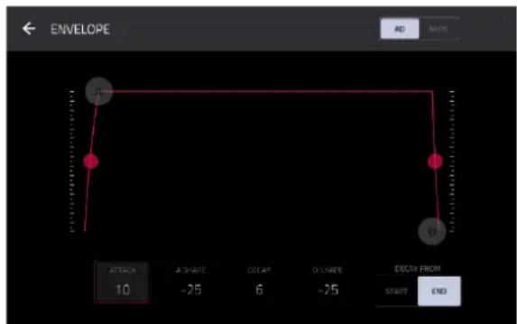
Use the A Shape and D Shape fields to adjust the curve of the Attack and Decay phases, respectively.
With ADSR envelopes, the following happens when you trigger a sample:
- Within the period of time defined by Attack, the sample volume rises to its maximum value.
- During the Decay phase, the sample's volume will gradually drop to the Sustain level.
- The sample's volume will stay at the Sustain level until the note is released.
- The sample's volume will drop to "zero" over the duration set by Release.

line
| Shape | Value | |---|---| | R | -25 | | S | 40 | | D | -25 | | SUSTARI | 45 | | RELEASE | 63 | | R SHAPE | -25 |Use the A Shape, D Shape and R Shape fields to adjust the curve of the Attack, Decay and Release phases, respectively.
Track Mute Mode

Track Mute Mode lets you easily mute tracks within a sequence or set track groups, enabling you to mute multiple tracks at once.
To enter Track Mute Mode, do either of the following:
- Press Menu, and then tap Track Mute.
- Press Track Mute (MPC X, MPC One, MPC Key 37), or press Mute (MPC Key 61).
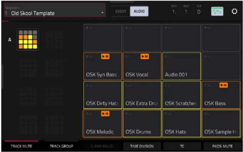
There are two tabs you can view in this mode: Track Mute or Track Group. Tap each button in the lower-left corner to select it.
Use the Sequence field at the top of the screen to select a sequence.
The Event/Audio toggle allows you to separately mute track events or mute audio on tracks that contain both MIDI and audio paths, including Drum, Plugin, and Keygroup tracks. MIDI and CV tracks will apply Event Mute regardless of the selection, and Audio tracks will apply Audio Mute regardless of the selection.
The Time Counter in the upper-right corner the current playhead position.
The automation button indicates the global Automation state.
Timing Correct (TC) lets you quantize track mutes. This is useful when you want your mutes to line up with a specific time division. For example, with Time Division set to 1 Bar, your mutes will always align with the beginning of the measure immediately after you press the pad.
Tap Time Division at the bottom of the screen, and select a value from 1/16 to 2 Bars (T indicates a triplet-based time division).
Tap TC at the bottom of the screen to enable or disable the Time Correct feature.
Tap Pads: Mute/Solo to cycle between track muting and soloing.
When using Track Soloing, tap the Clear Solos button to unsolo tracks that have been soloed.
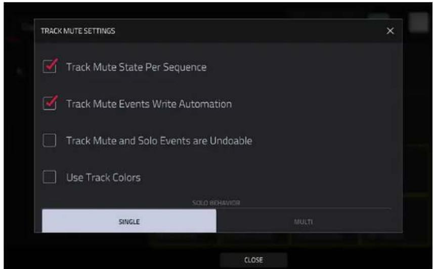
Tap the gear icon to open the Track Mute Settings window.
Check the Track Mute State Per Sequence box to maintain separate track mute statuses when changing sequences. This can allow you to create unique mute setups for each sequence, providing greater flexibility in live performance and arrangement creation.
Check the Track Mute Events Write Automation box to capture track muting and soloing when recording automation. Make sure the global automation button is set to W (write) before recording to capture track automation.
Check the Track Mute and Solo Events are Undoable to allow track mute and solo status to be undone and appear in the Undo History.
Check the Use Track Colors box to apply each track's color to the respective pads on the Track Mute page and on your hardware.
Use the Solo Behavior function to select whether only a Single track can be soloed at a time, or multiple tracks can be soloed together (Multi).
Track Mute
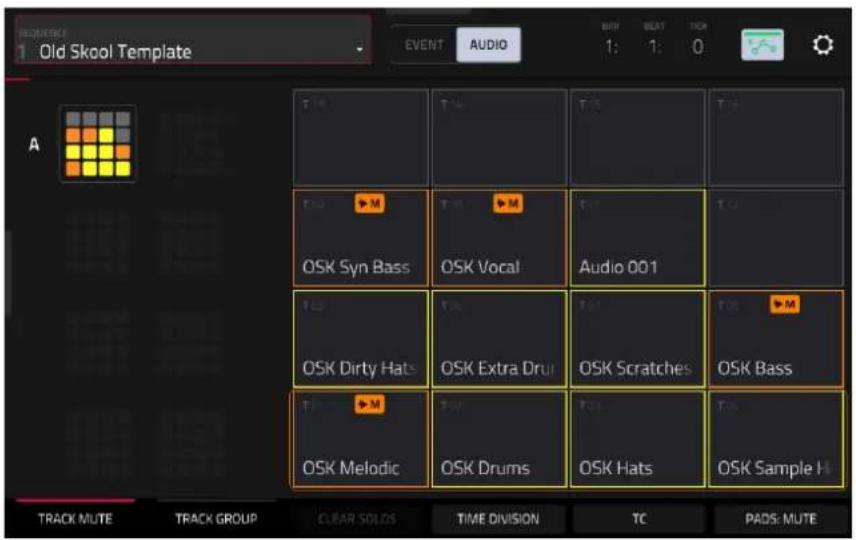
This is useful if you want to hear a sequence without a particular track (e.g., muting your keyboard track to focus on the bass) or if you want to isolate specific sounds or combinations of sounds that are separated by track.
Tip: This function is similar to, but more convenient than, muting tracks one at a time in the Track View.
To mute tracks in this mode:
- If the Track Mute tab in the lower-left corner is not already selected, tap it.
- Select the desired pad bank. Use the Pad Bank buttons or tap a pad bank shown on the left side of the screen.
- Select Event mute or Audio mute using the toggle in the toolbar.
- To mute or unmute a track, press the corresponding pad or tap it on the screen.
Pads for muted tracks are lit orange. Pads for unmuted tracks are lit according to the track color (or yellow if the Use Track Colors option is disabled in the Settings).
Event mutes are indicated by a MIDI plug icon, and can be applied to Drum, Plugin, Keygroup, MIDI, and CV tracks. Event mutes will silence new MIDI events but allow any currently playing events to ring out naturally.
Audio mutes are indicated by a waveform icon, and can be applied to Drum, Plugin, Keygroup, and Audio tracks.
Pads for unused tracks do not show any information.
To assign tracks to track groups within this tab, turn each of the Q-Link knobs (when the Screen Control Q-Link button is selected) to assign each of the pads to a track group. The number of each pad's track group is shown in its upper-right corner.
Track Group
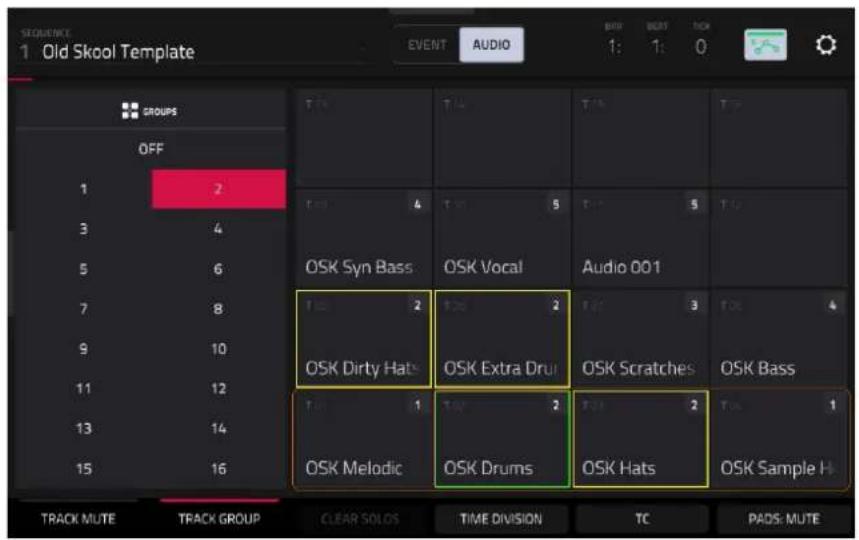
The track group feature extends the concept of track mutes: you can mute or unmute multiple tracks (in a single sequence) by pressing one pad that you have assigned to a track group. This is useful if you want to hear a track without a particular group of sounds or if you want to isolate specific sounds in various combinations. You can create up to 16 different track groups.
To assign tracks to track groups:
- If the Track Group tab in the lower-left corner is not already selected, tap it.
- Select the desired pad bank by using the Pad Bank buttons.
- To select a track to add to a mute group, press the corresponding pad or tap it on the screen. The pad for the selected track is lit green. If there are other pads for tracks in the same mute group, they will flash yellow.
- To add the track to a mute group, tap the number of the desired mute group.
To remove the track from the mute group, tap Off.
Alternatively, turn each of the Q-Link knobs (when the Screen Control Q-Link button is selected) to assign each of the pads to a track group. The number of each pad's track group is shown in its upper-right corner.
Pad Mute Mode

Pad Mute Mode lets you easily mute and solo pads within a track or set mute groups for each pad within a track.
To enter Pad Mute Mode, do either of the following:
- Press Menu, and then tap Pad Mute.
- Press Shift and Track Mute/Pad Mute (MPC X, MPC One, MPC Key 37), or Shift and Mute/Pad (MPC Key 61).

There are two tabs you can view in this mode: Pad Mute or Pad Group. Tap each button in the lower-left corner to select it. See the following Pad Mute and Pad Group sections to learn about each.
Use the Track field at the top of the screen to select a track. Pad Mute Mode is only compatible with Drum Tracks.
The Time Counter in the upper-right corner the current playhead position.
The automation button indicates the global Automation state.
Timing Correct (TC) lets you quantize pad mutes. This is useful when you want your mutes to line up with a specific time division. For example, with Time Division set to 1 Bar, your mutes will always align with the beginning of the measure immediately after you press the pad.
Tap Time Division at the bottom of the screen, and select a value from 1/16 to 2 Bars (T indicates a triplet-based time division).
Tap TC at the bottom of the screen to enable or disable the Time Correct feature.
Tap Pads: Mute/Solo to cycle between pad muting and soloing.
When using Track Soloing, tap the Clear Solos button to unsolo pads that have been soloed.

Tap the gear icon to open the Pad Mute Settings window.
Check the pad Mute and Solo Events Write Automation box to capture pad muting and soloing when recording automation. Make sure the global automation button is set to W (write) before recording to capture pad automation.
Check the Pad Mute and Solo Events are Undoable to allow pad mute and solo status to be undone and appear in the Undo History.
Check the Use Pad Colors box to apply each pad's color to the respective pads on the Pad Mute page and on your hardware.
Pad Mute


You can mute or unmute individual sounds (on a single track) in real time by pressing the pads. This is useful if you want to hear a track without a particular sound or if you want to isolate specific sounds or combinations of sounds.
Tip: This function is similar to muting pads one at a time in the grid—but more convenient.
To mute pads in this mode:
- If the Pad Mute tab in the lower-left corner is not already selected, tap it.
- Select the desired pad bank. Use the Pad Bank Buttons or tap a pad bank shown on the left side of the screen.
- To mute or unmute a pad's sound, press it or tap it on the screen. Muted pads are lit orange. Unmuted pads tracks are lit according to the pad color (or yellow if the Use Pad Colors option is disabled in the Settings). Unused pads do not show any sample names.
To assign pads to pad groups within this tab, turn each of the Q-Link knobs (when the Screen Control Q-Link button is selected) to assign each of the pads to a pad group. The number of each pad's group is shown in its upper-right corner.
Pad Group
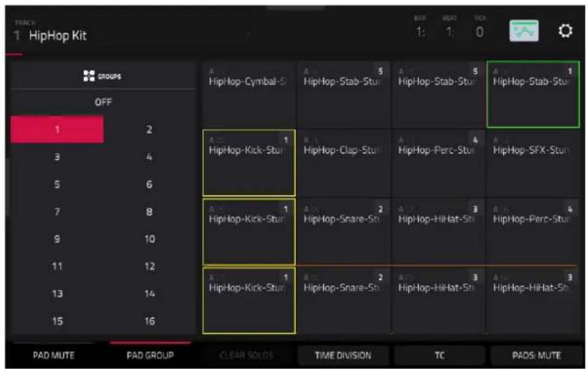
The pad group feature extends the concept of pad mutes: you can mute or unmute multiple pads (on a single track) by pressing one pad that you have assigned to a mute group. This is useful if you want to hear a track without a particular group of sounds or if you want to isolate specific sounds in various combinations. You can create up to 16 different pad groups.
To use pad groups:
- If the Pad Group tab in the lower-left corner is not already selected, tap it.
- Use the Pad Bank buttons to select the desired pad bank.
- To select a pad to add to a mute group, press it or tap it on the screen. The selected pad is lit green. If there are other pads in the same mute group, they will flash yellow.
- To add the pad to the mute group, tap the number of the desired mute group on the left side of the screen. To remove it from the mute group, tap Off.
Alternatively, turn each of the Q-Link knobs (when the Screen Control Q-Link button is selected) to assign each of the pads to a pad group. The number of each pad's group is shown in its upper-right corner.
Track View

Track View gives you an overview of the tracks of each sequence. Use this mode to edit tracks and sequences simultaneously.
To enter the Track View, do either of the following:
- Press Menu, and then tap Track View.
- Press Shift and Main/Track (MPC X, MPC Live, MPC Key 61, MPC Key 37).
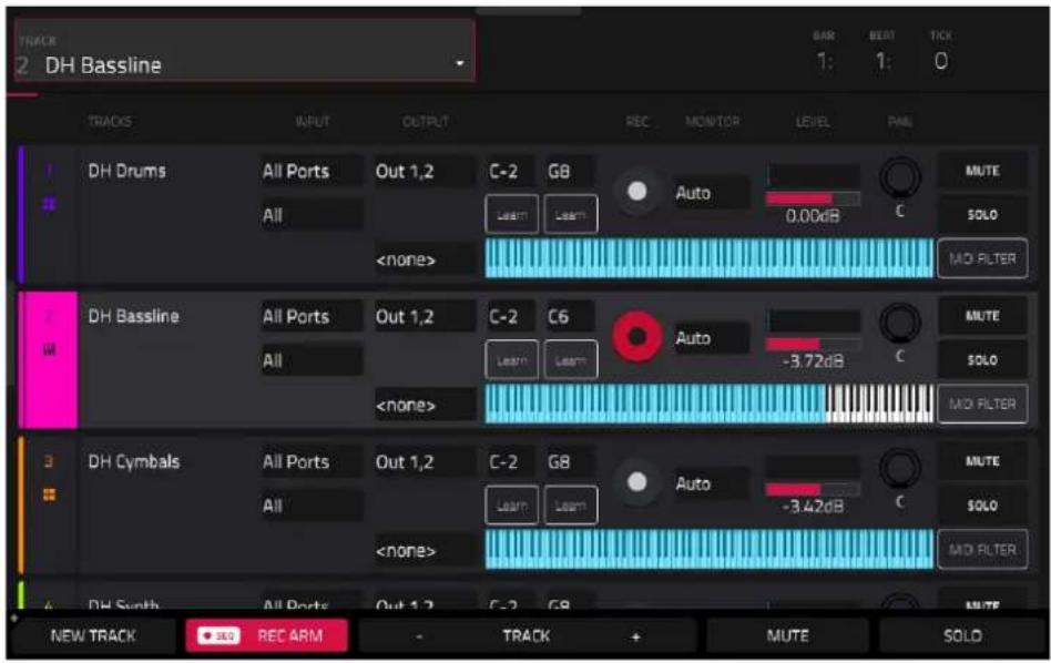
Each horizontal strip represents a track in the current sequence.
To move through the list of tracks, swipe up or down. You can also use the Track field at the top of the screen.
The top of the screen shows the track name and timing information.

Use the Track field to select the track in focus.
The Time Counter at the top of the screen indicates the current playhead position.
The bottom of the Track View screen contains the following functions:

Tap the New Track button to add a new track.
Tap the Rec Arm button to arm the sequence for recording.
Tap the Track – or Track + buttons to select the previous or next track (respectively). Alternatively, tap the track in the main part of the screen.
Tap Mute to mute the current track.
Tap Solo to solo the current track, muting all other tracks.
Press and hold Shift to access the following additional functions:
Tap Duplicate Track to immediately create an identical track on a new track.
Tap TC to open the Timing Correct (TC) settings.
Tap Click to open the Metronome (Click/Metro) settings.
Tap Track Settings to open the Track Settings window for the current track.

Use the Input field to set the track's MIDI or Audio input/inputs. For MIDI Inputs, you can also select the channel that the track will use.
Use the Output field to set the track's MIDI or Audio output/outputs. For MIDI Inputs, you can also select the channel that the track will use.
Use the Key Range fields to set the incoming range of notes that will be sent to the track (not available for Audio tracks). You can tap the low and high key fields and then use the data dial or +/- buttons, or tap the Learn button and use a connect MIDI device to set the key range. The set range will be shown in the keys diagram.
Use the Arm button to record-enable the track. When you begin recording, the MIDI input will be recorded to this track. You can select multiple tracks by pressing and holding Shift while tapping the Arm button to each track.
Use the Monitor button to set how your track will be monitored. Tapping it will cycle through its four states:
When set to Off, the track's input is not monitored, and playback of recorded events will be heard.
When set to In, the track's input is always monitored regardless of the track's Record Arm state, and playback from recorded events will not be heard.
When set to Auto, the track's input is monitored when the track is record armed, and playback of recorded events will be heard.
When set to Merge, the track's input is always monitored, and playback of recorded events will be heard.
Use the level slider to change the level of the track. The level meter above the slider shows the track's current level.
Use the pan knob to change the stereo panning of the track (not available for CV tracks).
Use the Solo and Mute buttons to solo or mute the track (respectively).
Alternatively, tap Mute or Solo (respectively) at the bottom of the screen to mute the currently selected track.
Tap the MIDI Filter button to open the Track MIDI Perform Settings window, where you can set parameters for incoming MIDI data.
- Note Range: This determines the Note Min and Note Max range that passes MIDI. Notes outside this range will not be heard in the track. You can also adjust this directly from Track View by using the Keyrange fields. Tap Learn and press the desired note for the Min and Max values.
- Velocity Range: This determines the Velocity Min and Velocity Max that passes MIDI. Velocities outside this range will not be heard in the track.
- MIDI CC Filter: Check these boxes to allow the listed MIDI Control Change messages to pass through the track. When unchecked, the MIDI CC message type will be ignored by the track. You can filter the following MIDI CC messages:
CC1 Modulation CC65 Pmento (Portamento) On/Off
CC2 Breath CC66 Sost (Sostenuto) On/Off
CC3 Undefined CC67 Soft Ped (Soft Pedal) On/Off
CC4 Foot CC68 Legato Switch
CC5 Portamento CC128 Pitchbend
CC7 Volume CC130 Program Change
CC10 Pan CC129 Channel Pressure
CC11 Expression CC131 Aftertouch
CC64 Sustain On/Off
Sample Edit Mode

Sample Edit Mode lets you edit samples using various functions.
To enter Sample Edit Mode, do any of the following:
- Press Menu, and then tap Sample Edit.
- Press Sample Edit (MPC X, MPC One, MPC Key 61, MPC Key 37) or Shift and Mute/Sample Edit (MPC Live II).

To select a sample to edit, use the Sample field at the top of the screen.
To edit the name of the sample, tap the keyboard icon next to the name at the top of the screen, and use the virtual keyboard that appears.
To delete the sample, tap the trash-can icon next to the name at the top of the screen. In the screen that appears, you will see the tracks that use this sample within your project. Tap Delete Sample to continue, or tap Cancel to return to the previous screen.
Tap the Stems icon to open the Create Stems Function in the Process Sample window. Learn more about this in Processing Slices & Samples.
Note: To purchase MPC Stems, visit akaipro.com/stems, and then activate your purchase in the Menu > Preferences > Activate Plugins menu.
The upper half of the screen shows the waveform. The lower half shows the editing controls.

The waveform display shows the “active” section of the sample waveform. Swipe left or right on the waveform to move through it.
Above the waveform is the timeline, shown in Samples, Time (in seconds and milliseconds), or Beats. You can select the measurement units you want to show in the Settings.
To zoom in or out, do any of the following:
- When the magnifying-glass icon (in the upper-right corner) is selected, spread or pinch your fingers (respectively) on the waveform.
- Tap the Zoom + or Zoom - buttons (respectively) at the bottom of the screen.
- Turn Q-Link Knob 4 (Zoom on MPC X) or the fourth Q-Link knob in the fourth column (MPC Live/Live II/One/Key 61/Key 37).
To scroll through the waveform, do either of the following:
- When the magnifying-glass icon (in the upper-right corner) is selected, swipe the waveform left or right.
- Turn Q-Link Knob 8 (Scroll on MPC X) or the third Q-Link knob in the fourth column (MPC Live/Live II/One/ Key 61/Key 37).
The green marker and red marker are the start point and end point (respectively). These two points define the region of the sample that will be played.
To move the start point or end point of the selected region, do any of the following:
• Tap and drag its marker left or right.
• Use the Start or End fields shown below the waveform.
- Use the first column of Q-Link knobs (Start X1_) to adjust the start point or the second column of Q-Link knobs (End X1_) to adjust the end point. The top-most Q-Link knobs (13 and 14) provide coarse adjustment. The bottom-most Q-Link knobs (1 and 2) provide fine adjustment.
Tip: A recorded sample may have some silence at the beginning or end, which makes it difficult to time it correctly in a musical context. Fix this by adjusting the start point. You can also adjust end point to remove any extra silence or unwanted audio at the end. In addition to making your workflow easier, having a “tight,” well-edited sample can enhance your production or performance.
You can use Sample Edit Mode in three different ways: Trim Mode, Chop Mode, or Pad Mode. The options for each mode are slightly different. Please refer to the following Trim Mode, Chop Mode, and Pad Mode parts of this chapter to learn how each works. Before using these modes, though, you may want to configure your settings—see the following Settings chapter to do this.
Settings
Tap the gear icon to open the Settings window, where you can configure certain Sample Edit Mode settings.

Use the Cue Play Mode selector to set how the cue playhead will play audio.
One Shot: Tapping Play Cue will play the entire sample from the cue playhead.
Toggle: Tapping Play Cue once will start playback from cue playhead. Tapping it once more will stop playback.
Use the Cue Preview selector to set if any audio plays as you move the cue playhead. As you move the cue playhead through the sample waveform, you can set it to play the small part of the sample before the cue playhead (Before), play the small part of the sample after the cue playhead (After), or not play at all (Off). You can also set this in your overall Preferences (see General Features >Menu >Preferences >General).
Use the Slice Preview selector to set if any audio plays as you move a slice marker. As you move the slice marker through the sample waveform, you can set it to play the small part of the sample before the slice marker (Before), play the small part of the sample after the slice marker (After), or not play at all (Off). You can also set this in your overall Preferences (see General Features >Menu >Preferences >General).
Use the Auto-Scroll selector to set how the screen behaves relative to the audio playhead.
Follow: Depending on the zoom setting, the waveform will scroll along in the background, keeping the audio playhead centered.
Page: The waveform display will move to the "next page" to follow the audio playhead.
Off: The waveform display will not move at all.
These functions also apply to the sample waveform in the Grid View.
Use the Timeline Units selector to set the measurement units shown above the sample waveform. You can select one of the following options:
Time: hours:minutes:seconds:frames
Samples: number of samples
Beats: bars:beats:ticks
Trim Mode
We recommend using Trim Mode to crop the start and/or ends from a sample.
To enter Trim Mode, tap the Trim/Chop button in the lower-left corner so it says Trim. There are two pages of parameters in Trim Mode, which can be accessed by tapping the > or < arrows on the sides of the page.
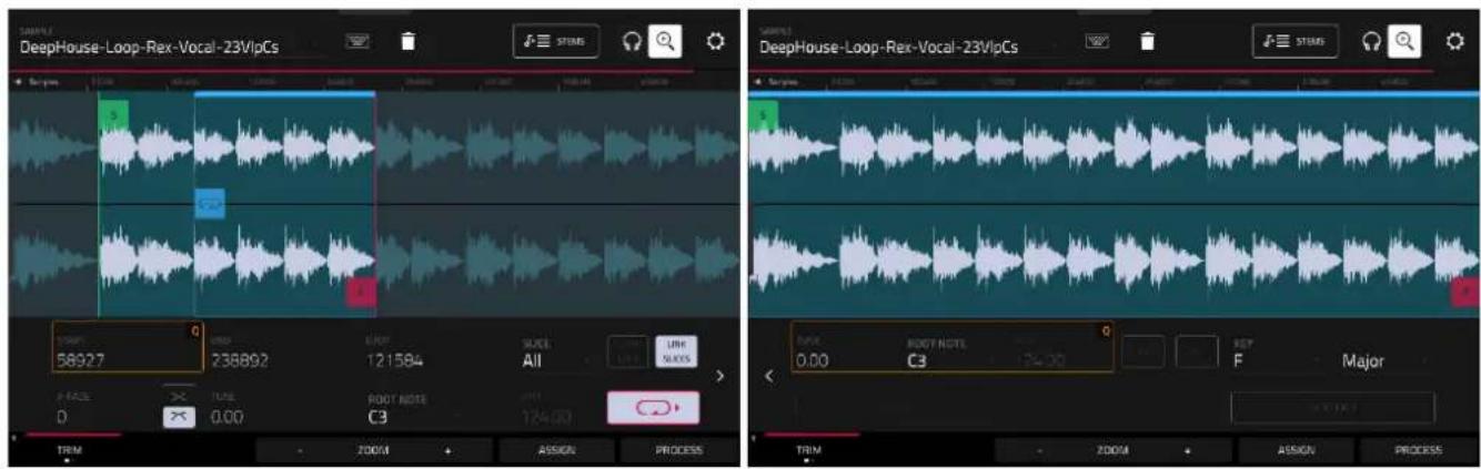
Use the Start and End fields to set the position of the start point and end point of the sample (respectively). Alternatively, tap and drag the start (S) or end (E) marker left or right, or use the first column of Q-Link knobs (Start X1_) to adjust the start point or the second column of Q-Link knobs (End X1_) to adjust the end point.
Trim Mode includes a loop function. When on, the region of the sample between the loop point and end point will repeat. This is useful when trying to find an ideal spot to begin the sample. The loop cannot be earlier than the start point.
To adjust the loop point, do any of the following:
• Use the Loop field.
- Tap and drag the start (S) marker (if Loop Lock is on) or the loop marker (if Loop Lock is off).
- Use the first column of Q-Link knobs (Start X1_; if Loop Lock is on) or the third column of Q-Link knobs (Loop X1_; if Loop Lock is off). The top-most Q-Link knobs (13 and 15) provide coarse adjustment. The bottom-most Q-Link knobs (1 and 3) provide fine adjustment.
Tap the Loop Lock button to turn Loop Lock on or off. When on, the loop point is the same as the start point. When off, the loop point is independent from the start point and indicated by a separate loop marker.
Tap the Loop button to turn the loop function on or off and cycle between the four modes:
Off: The sample will not loop.
Forward: When the loop reaches its end point, it will start playing again from the loop point.
Reverse: When the loop reaches its end point, it will play in reverse. When it reaches the loop point again, it will return to the end point and continue playing in reverse.
Alternating: When the loop reaches its end point, it will play in reverse. When it reaches the loop point again, it will start playing forward again from the loop point.
To switch between Forward and off, press and hold Shift, and then tap Loop at the bottom of the screen.
Use the X-Fade field to apply real-time crossfade looping to sample playback. To apply a crossfade, make sure the Loop starting point is greater than zero. Then, you can set the Length of the crossfade and the Type, either Equal Power or Linear.
Use your MPC hardware pads to play certain parts of the selected sample:
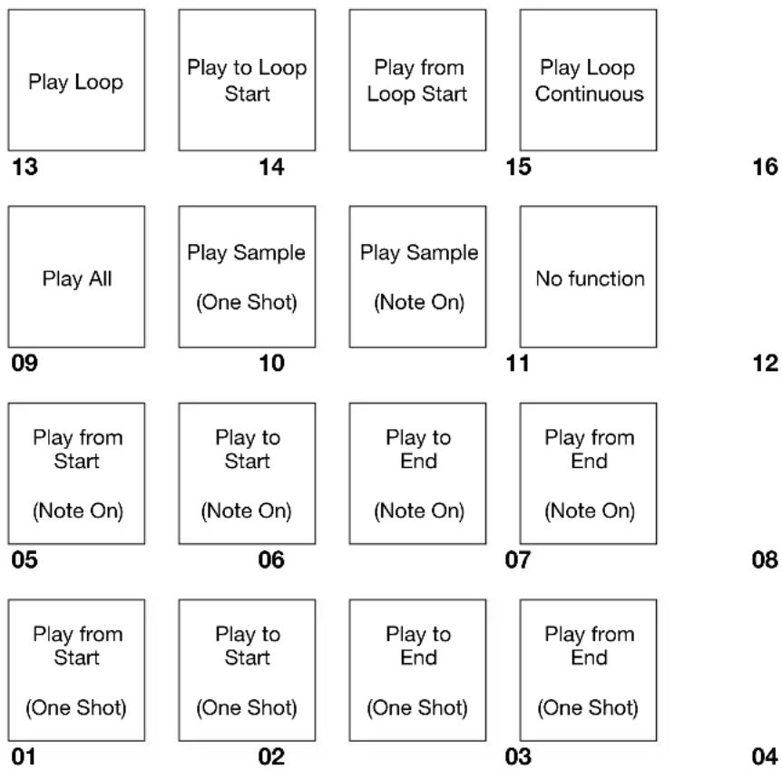
other
| Row | Row | Value | |---|---|---| | 01 | 13 | Play Loop | | 02 | 14 | Play to Loop Start | | 03 | 15 | Play from Loop Start | | 04 | 16 | Play Loop Continuous | | 05 | 09 | Play All | | 06 | 10 | Play Sample (One Shot) | | 07 | 11 | Play Sample (Note On) | | 08 | 12 | No function | | 09 | 05 | Play from Start (Note On) | | 10 | 06 | Play to Start (Note On) | | 11 | 07 | Play to End (Note On) | | 12 | 08 | Play from End (Note On) | | 13 | 13 | Play Loop | | 14 | 14 | Play to Loop Start | | 15 | 15 | Play Loop Continuous | | 16 | 16 | Play Loop Continuous | | 01 | 01 | Play from Start (One Shot) | | 02 | 02 | Play to Start (One Shot) | | 03 | 03 | Play to End (One Shot) | | 04 | 04 | Play from End (One Shot) | | 05 | 05 | Play from Start (Note On) | | 06 | 06 | Play to Start (Note On) | | 07 | 07 | Play to End (Note On) | | 08 | 08 | Play from End (Note On) | The values in the table represent the counts of each row. The numbers inside the boxes are explicitly labeled on the right side.Play Sample (One Shot) (Pad 10) plays the sample once from the start point to the end point. Press the pad once to play it.
Play Sample (Note On) (Pad 11) plays the sample once from the start point to the end point. Press and hold the pad to play it, and release the pad to stop playing it. Alternatively, select the headphones icon in the upper-right corner, and then tap and hold your finger on the waveform.
Play Loop Continuous (Pad 16) plays the sample repeatedly using the mode set by the Loop button (Forward, Reverse, or Alternating; if the Loop button is off, the sample will loop forward repeatedly).
Play Loop (Pad 13) plays the sample repeatedly using the mode set by the Loop button (Forward, Reverse, or Alternating; if the Loop button is off, the sample will loop forward repeatedly). Press and hold the pad to play it, and release the pad to stop playing it.
Play to Loop Start (Pad 14) plays the part of the sample just before the loop point. Press and hold the pad to play it, and release the pad to stop playing it.
Play from Loop Start (Pad 15) plays the sample from the loop point to the end of the sample regardless of the end point. Press and hold the pad to play it, and release the pad to stop playing it.
Play All (Pad 9) plays the entire sample.
Pads 1–4 have the same respective functions as Pads 5–8, but Pads 1–4 play the sample part as “One Shots” (pressing the pad once will play the entire part) while Pads 5–8 play the sample part as “Note Ons” (pressing the pad and holding it will play the part; releasing it will stop playback):
Play from Start (Pad 1, Pad 5) plays the sample from the start point to the end point.
Play to Start (Pad 2, Pad 6) plays the part of the sample just before the start point to the start point.
Play to End (Pad 3, Pad 7) plays the part of the sample just before the end point to the end point.
Play from End (Pad 4, Pad 8) plays the part of the sample from the end point to the end of the sample.
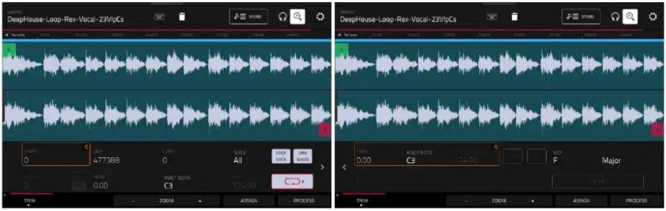
To select a slice to edit, do either of the following (after you have created slices in Chop Mode):
• Use the Slice field.
- Turn Q-Link Knob 16 (Select Slice on MPC X) or the fourth Q-Link knob in the fourth column (MPC Live/Live II/One/Key 61/Key 37).
When Link Slices is enabled (after you have created slices in Chop Mode), changing the start point of a slice will also change the end point of the previous slice. Similarly, changing the end point of a slice will also change the start point of the next slice. Disable Link Slices if you are trying to create slices that use non-contiguous parts of the sample.
To enable or disable this feature, tap the Link Slices button.
Important: Link Slices must be disabled to make slices non-sequential, noncontiguous, or overlapping.
Use either of the Tune fields to transpose the sample up or down from its original pitch.
Use either of the Root Note fields to set the root note of the sample. This defines which note will play the sample at its original pitch when in a keygroup track.
Use either of the BPM fields to manually set the BPM of the sample. On the second Trim Mode page, use the X2 and /2 buttons to double of halve the current tempo.
Use the Key fields to enter a sample key manually. One field selects the key root note, and the other field selects whether the key is Major, Minor, or off (--).
Tap Detect Key to detect the key automatically.
0 Snap forces start points, end points, and loop points to occur only at the waveform's "zero-crossings." This can help to avoid clicks and glitches when playing a sample.
To enable or disable 0 Snap, press and hold Shift, and then tap 0 Snap at the bottom of the screen.
Tip: You can use Trim Mode for a specific slice of the sample, previously created and selected in Chop Mode. This allows for a more detailed view of a single slice than in Chop Mode and gives you more options for auditioning the slice. You can easily switch between Trim Mode and Chop Mode while doing this.
To use both Trim Mode and Chop Mode to edit a sample slice:
- Tap Trim/Chop at the bottom of the screen so it says Chop.
- Set all fields as desired to create your sample slices.
- Select the desired slice using the Slice field.
- Tap Trim/Chop at the bottom of the screen so it says Trim. The region you are now editing is indicated by the normal start point and end point markers rather than slice markers.
- Tap Trim/Chop at any time to return to Chop Mode.
Tap From BPM to open the Edit Tuning window, which lets you tune a sample to the project.
Use the Beats field to match the number of beats in the sample.
Tap Match to tune the sample to the project. The Tune field will adjust automatically and close the window. The sample is now tuned to the project.
Tap To Project to tune the sample to the project and adjust the project tempo. This is the same as tapping Match, but it also changes the project's tempo to the BPM shown in the Tempo field on the right.
Tap Close to close the window.

Use the BPM field to enter a tempo manually.
Tap Detect to detect the tempo automatically. In the Edit BPM window that appears, you can do any of the following:
• Use the BPM field to enter a tempo manually.
- Tap Detect to detect the tempo automatically.
- Tap Tap Tempo at the bottom of the screen at the desired rate to use it as the tempo.
- Tap Close, the X, or anywhere outside the window to close it.

Assigning Samples
You can assign your new sample directly to a pad from Trim Mode.
To assign a sample, tap Assign at the bottom of the screen to open the Assign Sample window.
Important: Assigning a sample to a pad in this way will replace the sample on the first layer of the pad.
Tap Do It to assign the sample using the selected process.
Tap Close, the X, or anywhere outside the window to cancel the operation.
If you set the Assign To field to Assign slice to a pad, the pad will simply refer to the slice in this sample instead of creating a new sample. This is useful for reducing clutter in your project.
Use the Pad field to select the desired pad. Alternatively, press the desired pad.
Use the Slice Type field to select how the pad's layer settings will be set when the slice is assigned to it (see Track Edit Mode to learn more about the parameters mentioned below):
- Non-Destructive Slice: The pad's Slice setting will be set to the slice number.
- Pad Parameters: The pad's Slice setting will be set to Pad. The Pad Start and Pad End will be set to the slice's start point and end point values, and the Loop Position will be set to the slice's start point but with Pad Loop deactivated.
Use the Track field to specify the track to which you want to add the slice.

If you set the Assign To field to New Sample to Pad, this will create a new sample in your project. (The original sample will remain as it is.)
Use the Pad field to select the desired pad. Alternatively, press the desired pad.
Check the Crop Sample box to delete the unused parts from the sample when it's created and assigned. This feature is destructive, though the project will still contain your original sample.
Leave this box unchecked to keep the unused parts of the sample when it is created and assigned. This way, you will still be able to edit the entire sample further even though you are using only part of it at the moment.
Use the Track field to specify the track to which you want to add the slice.

Processing Slices & Samples
Tap the Process button to open the Process window, where you can select an editing option for the sample.
Use the Function field to select an editing process. Double-tap it or tap Function at the bottom of the screen to open the Function window, which displays an overview of all available editing processes.
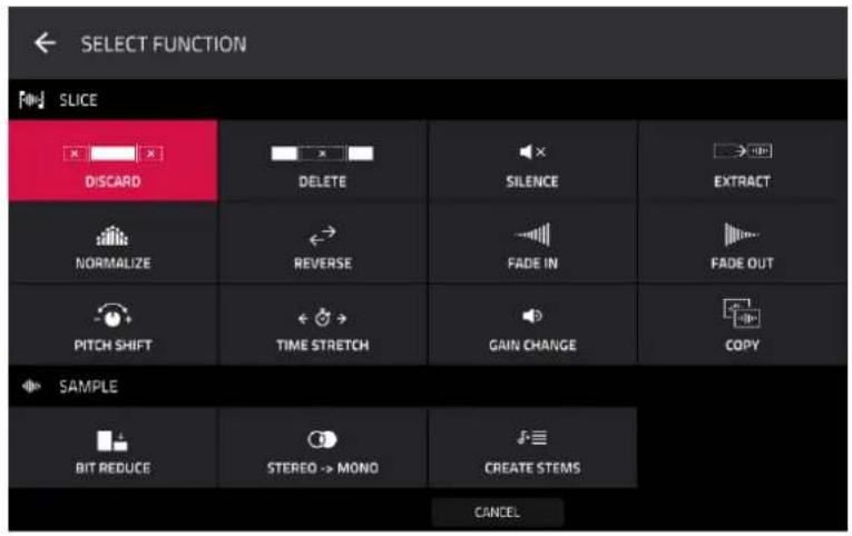
You can use any of these functions as described below.
Tap Cancel to return to Sample Edit Mode.
Tap the top of the screen to return to the Process window.
Note: All Slice processes will affect only the part of the sample between the start point and the end point. The Sample processes (Bit Reduce and Stereo -> Mono) will affect the entire sample regardless of its start point or end point.
The Discard process deletes the regions before the start point and after the end point.

The Delete process deletes the region between the start point and end point and closes the gap between them.
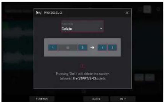
The Silence process replaces the region between the start point and end point with silence.

The Extract process deletes the regions before the start point and after the end point and saves it as a new sample in your current project.
Use the Edit Name field (and the virtual keyboard that appears) to name the new sample.
Tip: This is useful if you recorded a drum loop and wanted to remove just a snare drum hit, a kick drum hit, etc. to use separately in the project.

The Normalize process increases a sample's level to the highest level possible without distortion. This is essentially a kind of digital gain optimization, so you do not have to worry about excessive level settings when working with samples with a wide range of amplitudes.

The Reverse process reverses the region between the start point and end point.

The Fade In process sets a fade-in between the start point and end point. The following types are available:
- Linear fades the audio in with a linear curve—a straight line between the start and end.
- Square Root fades the audio in with a square root curve—a half-parabola that is similar to the logarithmic curve but steeper.
- Square fades the audio in with a curve opposite to the square root curve. This is similar to the exponential curve but steeper.
- Log fades the audio in with a logarithmic curve—quickly rising at the start and flattening out towards the end.
- Exp fades the audio in with an exponential curve—slowly rising in the beginning and growing steeper towards the end.
- Sine fades the audio in with a sine curve—like a sine wave, it slowly rises, gets steeper in the middle, and flattens out at the end.


Linear

Square

Root

Square

Log

Exp
The Fade Out process sets a fade-out between the start point and end point. These are the same as the Fade In curves, but fade the audio out instead of in.


Linear

Square

Root

Square

Log

Exp
The Pitch Shift process changes the pitch of the sample without changing its length. This lets you set the sample's pitch to your project without affecting the sample's tempo or duration. You can adjust it up to 12 semitones, up or down. Keep in mind that the audio quality may decrease at more extreme settings.
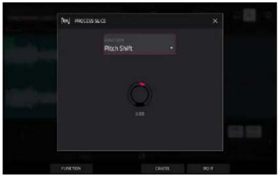
The Time Stretch process lengthens or shortens the sample without changing its pitch. This is useful for matching the durations of two samples with different pitches. You can enter the original tempo of the sample and the desired tempo after processing.
Use the Beat field to set the desired value number of beats.
Use the New Tempo field to set the new tempo. The Ratio field will then automatically show the time stretch factor.
Alternatively, to adjust the ratio instead, use the Ratio field to set the desired ratio. The New Tempo field will then change automatically based on the new time stretch factor.

The Gain Change process raises or lowers the volume of the sample. You can adjust it up to 18 dB, higher or lower. This function is different than Normalize because it will allow volumes beyond clipping level. This may be a desired effect, but remember to watch your output level!
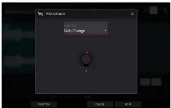
The Copy process saves a copy of the sample.
Use the Edit Name field (and the virtual keyboard that appears) to name the new sample. Otherwise, the process will add a consecutive number after the sample name.
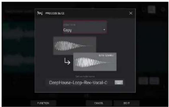
The Bit Reduce process lowers the bit resolution of a sample, effectively reducing its degree of faithful reproduction. You can reduce it down to 1 bit. (The sound is similar to the Resampler effect, but Bit Reduce will permanently alter the sample.)
Tip: Use this on drum loops to get a dirty, "old-school" sizzle but with a digital "edge."
Note: This process affects the entire sample regardless of its start point or end point.
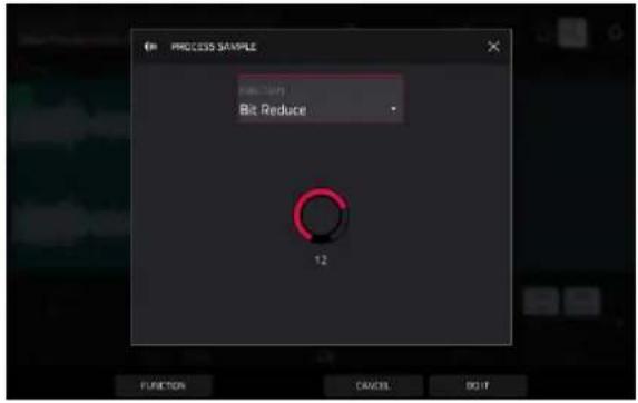
The Stereo -> Mono process converts a stereo sample to a new mono sample and saves it as a new sample.
Use the Edit Name field (and the virtual keyboard that appears) to name the new sample. Otherwise, the process will add a consecutive number after the sample name.
The following options are available:
• Left will convert the left channel only.
• Right will convert the right channel only.
- Sum will combine the left and right audio channels to a single mono channel.
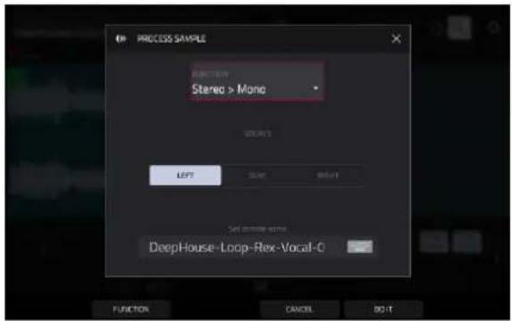
Note: This process affects the entire sample regardless of its start point or end point.
The Stems process isolates different parts of the sample and separates them into new stem samples.
Click the icons to select or deselect from the following elements to create stems of:
• Vocals: Isolate vocal elements of the track into a stem.
- Bass: Isolate bass elements of the track into a stem.
- Drums: Isolate percussive elements of the track into a stem.
- Other: Isolate other musical textures, such as keys or guitars, into a stem.

Use the Track dropdown menu to select the track where the stems will be added.
The Assign to Pad function determines where the stem separated samples are added. When checked, you can select a pad in the chosen Track using the dropdown menu, and the stems will be added to the first four layers of that pad. When unchecked, the stems will be added to the general project sample pool in the Project Info Browser.
Tap the Use trimmed sample box to trim the source sample between the Start and End points before applying the stem separation process.
Tip: Uncheck this box if you want to retain stemmed results, otherwise, they will be bypassed.
Note: To purchase MPC Stems, visit akaipro.com/stems, and then activate your purchase in the Menu > Preferences > Activate Plugins menu.
slices with the
Chop Mode
Whereas Trim Mode crops only the start and/or end off of a sample, Chop Mode divides the sample into multiple regions called slices. We recommend using Chop Mode when working with a long sample with different sounds throughout (e.g., a drum loop or a long melodic or harmonic passage).
To enter Chop Mode, tap the Trim/Chop button in the lower-left corner so it says Chop.

Use the Start and End fields to set the position of the start point and end point (respectively) of the currently selected slice. Alternatively, tap and drag the start (S) or end (E) marker left or right, or use the first column of Q-Link knobs (Start X1_) to adjust the start point or the second column of Q-Link knobs (End X1_) to adjust the end point.
Use the selector in the lower-left corner of the screen to choose how you want to use Chop Mode:
Manual
This method lets you insert slices at locations you select.
Threshold
This method uses an adjustable detection algorithm that derives the number of slices created from the volume levels present in the sample.
Use the Threshold field to set the threshold level. Alternatively, turn Q-Link Knob 11 (Threshold on MPC X) or the second Q-Link knob in the third column (MPC Live/Live II/One/Key 61/Key 37). The higher the selected value, the more slices will be created.
Use the Min Time field to set the minimum length of a slice in milliseconds.
Regions
This method divides a sample into several slices of equal length.
Use the Regions field to set how many regions the sample will be divided into. Alternatively, turn Q-Link Knob 11 (Num Regions on MPC X) or the second Q-Link knob in the third column (MPC Live/Live II/One/Key 61/Key 37/Touch). The higher the selected value, the more slices will be created.
BPM
This method divides a sample into several slices based on the tempo (beats per minute).
Use the Bars field to set how many bars are in the sample. Alternatively, turn Q-Link Knob 11 (Bars on MPC X) or the second Q-Link knob in the third column (MPC Live/Live II/One/Key 61/Key 37).
Use the Beats field to set how many beats are in each bar. Alternatively, turn Q-Link Knob 7 (Beats on MPC X) or the third Q-Link knob in the third column (MPC Live/Live II/One/Key 61/Key 37).
Use the Time Div field to set a note division. Alternatively, turn Q-Link Knob 3 (Time Div on MPC X) or the fourth Q-Link knob in the third column (MPC Live/Live II/One/Key 61/Key 37). The slice markers will be placed according to this setting. You can select 1/4, 1/8, 1/16, or 1/32. (In most cases, you should set this parameter to 1/16.)
To play a slice, do either of the following:
- Press the pad that corresponds to the slice. If your sample has more than 16 slices, use the additional pad banks.
- When the headphones icon (in the upper-right corner) is selected, tap a slice in the waveform.
When the One Shot feature is enabled, you can press a pad once to play the entire slice. When this is disabled, pressing the pad and holding it will play the slice; releasing it will stop playback.
To enable or disable One Shot, press and hold Shift, and then tap One Shot.
To select a slice to edit, do any of the following:
• Use the Slice field.
- Turn Q-Link Knob 16 (Select Slice on MPC X) or the first Q-Link knob in the fourth column (MPC Live/Live II/One/Key 61/Key 37).
- When the headphones icon (in the upper-right corner) is selected, tap a slice in the waveform.
To add a slice at the current playhead position, tap Slice+ at the bottom of the screen. You can do this at any point during sample playback.
To insert a slice marker during sample playback, press an unlit pad (usually Pad 1) to start playback of the sample, and then press an unlit pad during playback to place a slice marker at each location of the playhead. (If you press a lit pad, playback will restart from that pad's corresponding slice marker.) The number of the pad that is lit green is the number of the most-recently inserted slice marker. The numbers of the pads that are lit yellow are the numbers of the slice markers that are already inserted.
To split or combine slices, tap the glue-and-scissors icon. In the Split/Combine Region screen that appears, tap one of the following buttons:
- Split: This splits the currently selected region into two equal slices.
- Combine: This combines the currently selected region with the one before it.
• Back: This closes the window.


When Link Slices is enabled, changing the start point of a slice will also change the end point of the previous slice. Similarly, changing the end point of a slice will also change the start point of the next slice. Disable Link Slices if you are trying to create slices that use non-contiguous parts of the sample.
To enable or disable this feature, tap the Link Slices button.
Important: Link Slices must be disabled to make slices non-sequential, noncontiguous, or overlapping.
To remove all slices from a sample, press and hold Shift and tap Clear All.
The cue playhead is useful when manually inserting slice markers. You can set its position and behavior to suit your workflow.
Use the Cue field to adjust the position of the cue playhead. Alternatively, tap and drag the translucent marker with the triangle (▶).
To play the sample from the cue playhead, tap Play Cue at the bottom of the screen.
To create a slice marker at the cue playhead position, tap Slice+ at the bottom of the screen.
To set how the cue playhead behaves, use the Settings window (described earlier).
0 Snap forces start points and end points to occur only at the waveform's "zero-crossings." This can help to avoid clicks and glitches when playing a sample.
To enable or disable 0 Snap, press and hold Shift, and then tap 0 Snap at the bottom of the screen.
Converting or Assigning Slices
You can assign your new sample directly to a pad from Chop Mode. You can also convert it into a new track or patched phrase.
To convert or assign a sample, press and hold Shift, and then tap Convert at the bottom of the screen to open the Convert or Assign Slices window.
To convert the sample using the selected process, tap Do It.
To cancel the operation, tap Close.
If you set the Convert To field to New drum track using slices, this will create a new track and assign the sample's slices to its pads. The pads will simply refer to the slices in this sample instead of creating new samples. This is useful for reducing clutter in your project. The new track will be named after the sample and appended with ch.
Use the Slice Type field to select how each pad's layer settings will be set when the slices are assigned to them (see Track Edit Mode to learn more about the parameters mentioned below):
- Non-Destructive Slice: Each pad's Slice setting will be set to the slice number.
- Pad Parameters: Each pad's Slice setting will be set to Pad. The Pad Start and Pad End parameters will be set to the slice's start point and end point values, and the Loop Pos parameter will be set to the slice's start point but with Pad Loop deactivated.
Check the Create Events box to automatically create a new sequence in which each pad plays its corresponding slice in ascending sequence by pad number.
If Create Events is checked, use the Bars field to set how many bars the slices' events will occupy.

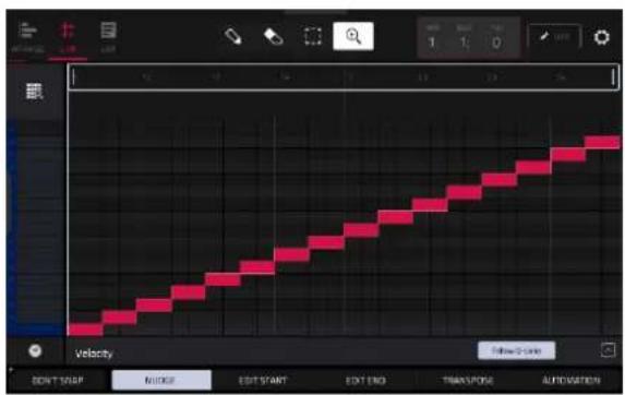
If you set the Convert To field to Create New Samples, this will create a new sample from each slice and assign them to pads in a new track.
The new track will be named after the sample and appended with ch. The new samples will be appended with SI-# (where # is a consecutive number).
Check the Crop Samples box to delete the unused parts from the sample when they are created and assigned. This feature is destructive, though the project will still contain your original sample.
Leave this box unchecked to keep the unused parts of the samples when they're created and assigned. This way, you will still be able to edit the entire samples further even though you are using only part of them at the moment.
By default, this option already will create a new track. You can uncheck the Create new track box to convert each slice into a sample that is placed in the project's sample pool but not assigned to a track or pad.
If Create new track is checked, check the Create events box to automatically create a new track in which each pad plays its corresponding slice in ascending sequence by pad number.
If Create Events is checked, use the Bars field to set how many bars the slices' events will occupy.
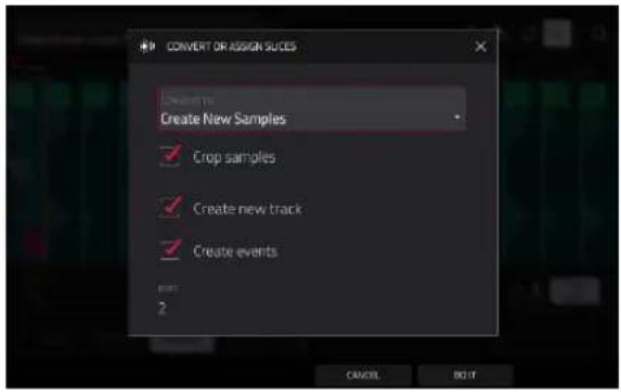
If you set the Convert To field to Audio Track from Samples, this will create a new audio track with the converted samples. The new track will be named after the sample.
By default, this option already will create a new track. You can uncheck the Create new track box to select an existing Audio track in the project where the samples will be added.
Check the Warp Events box to warp the converted samples to the project tempo.
Use the Bars field to set how many bars the slices' events will occupy.
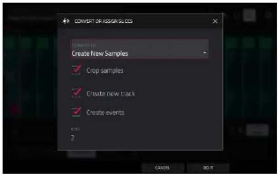
If you set the Convert To field to Assign Slice to Pad, the pad will simply refer to the slice in this sample instead of creating a new sample. This is useful for reducing clutter in your project.
Important: Assigning a sample to a pad in this way will replace the sample on the first layer of the pad.
Use the Pad field to select the desired pad. Alternatively, press the desired pad.
Use the Slice Type field to select how the pad's layer settings will be set when the slice is assigned to it (see Track Edit Mode to learn more about the parameters mentioned below):
- Non-Destructive Slice: The pad's Slice setting will be set to the slice number.
- Pad Parameters: The pad's Slice setting will be set to Pad. The Pad Start and Pad End will be set to the slice's start point and end point values, and the Loop Position will be set to the slice's start point but with Pad Loop deactivated.
Use the Track field to specify the track to which you want to add the slice.

If you set the Convert To field to New Sample to Pad, this will create a new sample in your project. (The original sample will remain as it is.)
Important: Assigning a sample to a pad in this way will replace the sample on the first layer of the pad.
Use the Pad field to select the desired pad. Alternatively, press the desired pad.
Check the Crop Sample box to delete the unused parts from the sample when it's created and assigned. This feature is destructive, though the project will still contain your original sample.
Leave this box unchecked to keep the unused parts of the sample when it is created and assigned. This way, you will still be able to edit the entire sample further even though you are using only part of it at the moment.
Use the Track field to specify the track to which you want to add the slice.

If you set the Convert To field to Patched phrase, this will create a new sample that will play based on the tempo of your project, and places it in the current project. The patched phrase will have the same name as the original sample but appended with pp and will use a different icon when viewing your project information.
Use the Bars field to set how many bars long the patched phrase is meant to be.
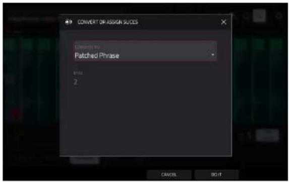
Processing Slices
Press and hold Shift, and then tap the Process button to open the Process window, where you can select an editing option for the currently selected slice. (This has fewer options than Trim Mode. Unavailable ones are darkened.)
Use the Function field to select an editing process. Double-tap it or tap Function at the bottom of the screen to open the Function window, which displays an overview of all available editing processes.
Important: Chop Mode is non-destructive: You can choose the slice/edit behavior without destroying your original sample, giving you more control over sample playback; you can save your sliced sample and but also reuse all of the slice data in another project. See the Track Edit Mode chapter to learn more about setting a pad to play the entire sample, a specific slice of a sample, or a specific region of the sample (independent of its slice markers).

You can use any of these functions as described below.
To return to Sample Edit Mode, tap Cancel.
To return to the Process window, tap the top of the screen.
Note: All processes here will affect only the currently selected slice.
The Silence process replaces the region between the start point and end point with silence.

The Extract process deletes the regions before the start point and after the end point and saves it as a new sample (with a name you enter) in your current project.
Tip: This is useful if you recorded a drum loop and wanted to remove just a snare drum hit, a kick drum hit, etc. to use separately in the project.

The Normalize process increases a sample's level to the highest level possible without distortion. This is essentially a kind of digital gain optimization, so you do not have to worry about excessive level settings when working with samples with a wide range of amplitudes.

The Reverse process reverses the region between the start point and end point.

The Fade In process sets a fade-in between the start point and end point. The following types are available:
- Linear fades the audio in with a linear curve—a straight line between the start and end.
- Square Root fades the audio in with a square root curve—a half-parabola that is similar to the logarithmic curve but steeper.
- Square fades the audio in with a curve opposite to the square root curve. This is similar to the exponential curve but steeper.
- Log fades the audio in with a logarithmic curve—quickly rising at the start and flattening out towards the end.
- Exp fades the audio in with an exponential curve—slowly rising in the beginning and growing steeper towards the end.
- Sine fades the audio in with a sine curve—like a sine wave, it slowly rises, gets steeper in the middle, and flattens out at the end.


Linear

Square

Root

Square

Log

Exp
The Fade Out process sets a fade-out between the start point and end point. These are the same as the Fade In curves, but fade the audio out instead of in.


Linear

Square

Root

Square
Log

Exp
The Pitch Shift process changes the pitch of the sample without changing its length. This lets you set the sample's pitch to your project without affecting the sample's tempo or duration. You can adjust it up to 12 semitones, up or down. Keep in mind that the audio quality may decrease at more extreme settings.
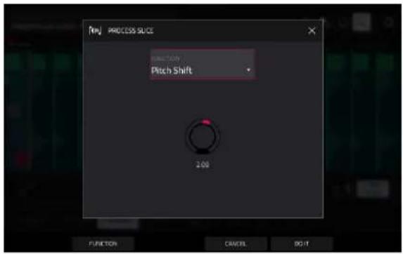
The Gain Change process raises or lowers the volume of the sample. You can adjust it up to 18 dB, higher or lower. This function is different than Normalize because it will allow volumes beyond clipping level. This may be a desired effect, but remember to watch your output level!

The Stems process to isolates different parts of the sample and separate them into new stem samples.
Click the icons to select or deselect from the following elements to create stems of:
• Vocals: Isolate vocal elements of the track into a stem.
- Bass: Isolate bass elements of the track into a stem.
- Drums: Isolate percussive elements of the track into a stem.
- Other: Isolate other musical textures, such as keys or guitars, into a stem.
Use the Track dropdown menu to select the track where the stems will be added.
The Assign to Pad function determines where the stem separated samples are added. When checked, you can select a pad in the chosen Track using the dropdown menu, and the stems will be added to the first four layers of that pad. When unchecked, the stems will be added to the general project sample pool in the Project Info Browser.
Tap the Use trimmed sample box to trim the source sample between the Start and End points before applying the stem separation process.

Tip: Uncheck this box if you want to retain slices with the stemmed results, otherwise, they will be bypassed.
Note: To purchase MPC Stems, visit akaipro.com/stems, and then activate your purchase in the Menu > Preferences > Activate Plugins menu.
Pad Mode
Pad Mode lets you edit a sample in the context of the track in which you'll use it. You can adjust the pad parameters as though you were in Track Edit Mode, auditioning and hearing how it will sound in the track's audio path.
To enter Pad Mode, tap the Pad button at the bottom of the screen. The pads will show their assigned samples in the current Track.
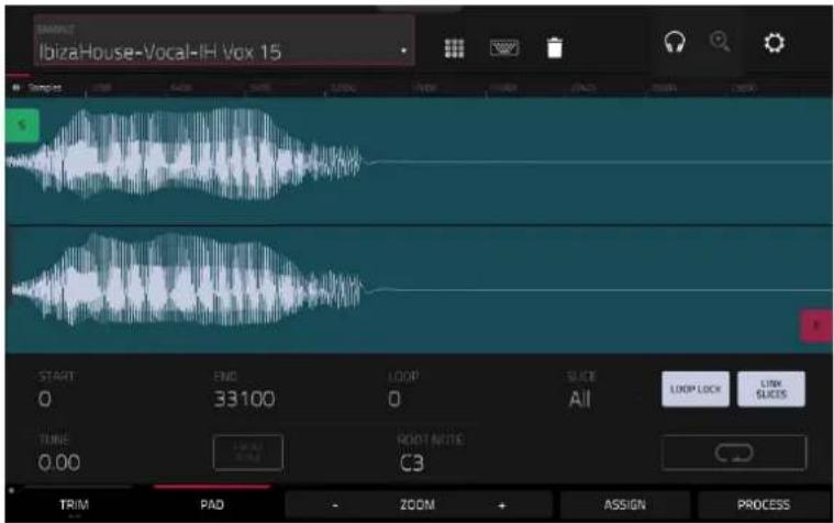
Use the Start and End fields to set the position of the start point and end point of the sample (respectively). Alternatively, tap and drag the start (S) or end (E) marker left or right, or use the first column of Q-Link knobs (Start X1_) to adjust the start point or the second column of Q-Link knobs (End X1_) to adjust the end point.
Pad Mode includes a loop function. When on, the region of the sample between the loop point and end point will repeat. This is useful when trying to find an ideal spot to begin the sample. The loop cannot be earlier than the start point.
To adjust the loop point, do any of the following:
• Use the Loop field.
- Tap and drag the start (S) marker (if Loop Lock is on) or the loop marker (if Loop Lock is off).
- Use the first column of Q-Link knobs (Start X1_; if Loop Lock is on) or the third column of Q-Link knobs (Loop X1_; if Loop Lock is off). The top-most Q-Link knobs (13 and 15) provide coarse adjustment. The bottom-most Q-Link knobs (1 and 3) provide fine adjustment.
To turn Loop Lock on or off, tap the Loop Lock button. When on, the loop point is the same as the start point. When off, the loop point is independent from the start point.
To turn the loop function on or off, tap the Loop button to cycle between the four modes:
Off: The sample will not loop.
Forward: When the loop reaches its end point, it will start playing again from the loop point.
Reverse: When the loop reaches its end point, it will play in reverse. When it reaches the loop point again, it will return to the end point and continue playing in reverse.
Alternating: When the loop reaches its end point, it will play in reverse. When it reaches the loop point again, it will start playing forward again from the loop point.
To switch between Forward and off, press and hold Shift, and then tap Loop at the bottom of the screen.
Tap each pad to hear its sample/samples. The sample on its first layer will automatically appear in the waveform display for editing.
Use the Tune field to transpose the sample up or down from its original pitch.
Tap From BPM to open the Edit Tuning window, which lets you tune a sample to the current sequence.

Use the Number of Beats field to match the number of beats in the sequence.
To tune the sample to the project, tap Match. The Tune field will adjust automatically and close the window. The sample is now tuned to the sequence.
To tune the sample to the project and adjust the project tempo, tap To Project. This is the same as tapping Match but it also changes the project's tempo to the BPM shown in the Tempo field on the right.
To close the window, tap Close.
Use the Root Note field to set the root note of the sample. This defines which note will play the sample at its original pitch when in a keygroup track.
Use the Slice field to display either the sample as it has been edited (Pad) or the entire sample (All).
If the Slice field is set to All, you can display the sample as it has been edited but keep the start point and end point. To do this, press and hold Shift, and then tap To Pad at the bottom of the screen. The Slice field will change to Pad, but the start point and end point will remain in their current locations.

The Link Slices button does not have a function in Pad Mode.
0 Snap forces start points, end points, and loop points to occur only at the waveform's "zero-crossings." This can help to avoid clicks and glitches when playing a sample.
To enable or disable 0 Snap, press and hold Shift, and then tap 0 Snap at the bottom of the screen.
To enable or disable the loop function, press and hold Shift, and then tap Loop at the bottom of the screen. This switches the loop function between Forward and off. The loop function is described earlier.
Assigning Samples
You can assign your new sample directly to a pad from Pad Mode.
To assign a sample, tap Assign at the bottom of the screen to open the Assign Sample window.
Important: Assigning a sample to a pad in this way will replace the sample on the first layer of the pad.
The Pad Mode Assign functions are identical to Trim Mode. See Trim Mode > Assigning Samples to learn more.
Processing Slices & Samples
Tap the Process button to open the Process window, where you can select an editing option for the sample.
Use the Function field to select an editing process. Double-tap it or tap Function at the bottom of the screen to open the Function window, which displays an overview of all available editing processes.

You can use any of these functions as described below.
To return to Sample Edit Mode, tap Cancel.
To return to the Process window, tap the top of the screen.
Note: All Slice processes will affect only the part of the sample between the start point and the end point. The Sample processes (Bit Reduce and Stereo -> Mono) will affect the entire sample regardless of its start point or end point.
The Pad Mode Functions are identical to Trim Mode. See Trim Mode > Processing Slices & Samples to learn more.
Sampler
The Sampler lets you record audio samples to use in your projects.
To open the Sampler, do any of the following:
- Press Menu and then tap Sampler.
- Press Sampler (MPC X, MPC One), Shift and Mix/Sampler (MPC Live II), or Shift and Sample Edit/Sampler (MPC Key 61, MPC Key 37).
- In Main Mode, select an empty pad in a Drum Track. Then, tap the Record icon in the Track Section.
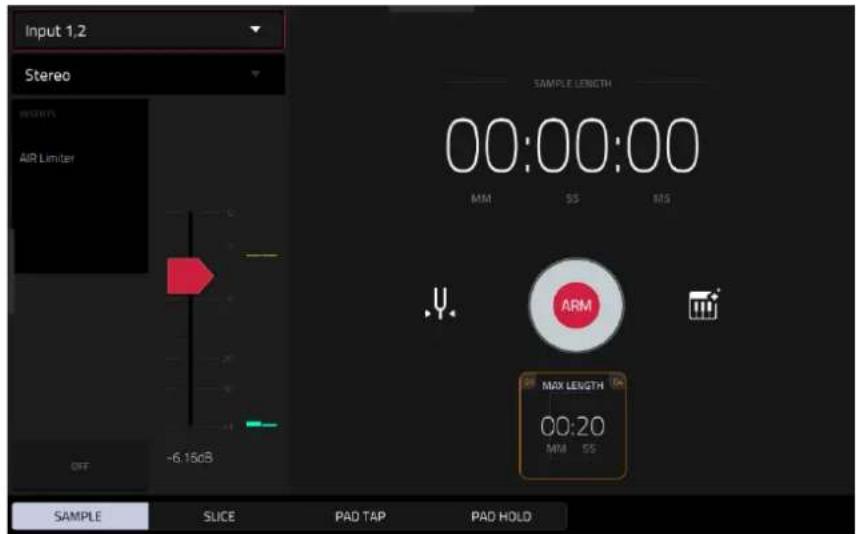
To set up the Sampler before recording:
- Make sure to reduce the volume levels of your audio source and speakers, headphones, and/or monitors before you make any connections to avoid "pops" or feedback.
- Connect a synthesizer or other line-level audio source to the input/inputs of your MPC hardware.
- Turn the 3/4 Rec Gain (MPC X), Gain (MPC Key 61), or Rec Vol (MPC Live, MPC Live II, MPC One, MPC Key 37) knob to set the input level while playing your audio source. You should now see the level in the meter. Make sure it does not exceed the maximum level (the meter should not be "peaking" constantly).
- Set the recording controls as desired (described in this chapter).
- Tap the Arm button to record-arm the Sampler.
You can use the Sampler to record using four different methods: Sample, Slice, Pad Tap, or Pad Hold, all described later in this chapter. The following controls are present regardless of which method you use.
The Sampler page also contains the Auto Sampler, which lets you capture and convert any plugin preset or external instrument preset into a Keygroup sampler patch.
Tap the tuning fork icon to open the Tuner.
The upper-left Input Source field defines whether you are going to record an external audio signal, which you can set to the pair of inputs (Input 1,2) or a single input (Input 1-2). You can also select an internal signal from within your MPC hardware (Resample L, Resample R, or Resample L+R).
Resampling does not require an audio connection because the source is internal and is therefore recorded without any loss in audio quality. You can, for example, use Resample to record two or more samples by pressing the corresponding pads simultaneously.
Use the second upper-left Mono/Stereo field to choose whether your recorded samples will be monaural (Mono) or binaural (Stereo).
The Inserts field shows any enabled or disabled effects for the Sampler. Tap the area under Inserts to open a window where you can load, change, and enable or disable the effects.
Important: These effects are applied to the audio as you record it. This means that the effects cannot be “removed” from the sound later. Learn more about how effects work in General Features > Effects.
Tap the Monitor button to enable or disable input monitoring. When on, the audio you hear in your headphones will be taken before it reaches the Sampler, ensuring zero latency. When off, the audio you hear in your headphones will be taken after it is processed in the Sampler, so there may be some latency, but you will hear the audio source as it sounds in the recording.
Tip: To avoid possible clicks or feedback while input monitoring, reduce the level of the audio sources.
Use the threshold slider to adjust the threshold. Alternatively, turn Q-Link 1 when the Q-Links are set to screen mode.
When the Sampler is record-armed, it automatically starts recording when the level of the incoming source exceeds this setting. If you set it too high, the recording may not start when you play the input source, or the start of the material you wanted to record may be missing. If you set it too low, the recording may start too early, before you play the external source. Set this parameter to an appropriate level using the level meter.
To reset the "peak hold," which shows the highest level of your input signal in the level meter, tap it.

For reference, the Sample Length counter shows you the length of your sample during the recording procedure.
Tap Arm to record-arm the Sampler. The button will then change to Record and show Waiting for signal.
At that point, start recording by doing either of the following:
- Start performing so that the incoming audio level exceeds the level of the threshold slider.
• Tap Record under the Sample Length counter.
To disarm the track instead, tap Cancel.

Use the Max Length field to define the maximum sampling time.
You can record up to 60 minutes (60:00) per sample. We recommend setting these to values that roughly match your estimated recording duration. The default value is 20 seconds.
Sample
Using this method, you can insert slice markers directly in your sample as you record it.
Slice markers divide the sample into multiple regions called slices, which you can adjust in Sample Edit Mode > Chop Mode. This is useful when working with a long sample with different sounds throughout (e.g., a drum loop or a long melodic or harmonic passage).

To start recording, do one of the following:
- Start performing so that the incoming audio level exceeds the level of the threshold slider.
• Tap Record under the Sample Length counter.
To insert a slice marker in a sample while recording, tap Slice+ (in the lower-right corner) as the sample records. Each time you tap it, a slice marker will be placed at that location.
To stop recording, tap Stop under the Sample Length counter.
After you stop your recording, the Keep or Discard Sample window will appear.

Use the Edit Name field to name the new sample. Tap it and use the virtual keyboard that appears.
Use the Track field to assign the new sample to a track. Select
Use the Assign to Pad field to assign the sample to a pad in the track.
Use the Root Note field to set where the sample's original pitch will be on the keyboard.
If you recorded a sample while a sequence was playing, the Keep or Discard Sample window will show a few more options after you select a pad.
Check the Add Event box to automatically add the sample to the currently playing sequence.
Use the At field to select where you want the event to start:
• Start: The sample will be a note event at the start of the currently playing sequence.
- Trigger: The sample will be a note event where you began recording it in the currently playing sequence.
Tap Keep at the bottom of the screen to confirm your selections.
Tap Discard at the bottom of the screen to discard the recording and return to the Sampler.
Tap Play at the bottom of the screen to play the recording.
Tap Edit to save the sample and open Sample Edit Mode to edit your recorded sample.
Slice
Using this method, the pads correspond to slices of the currently recorded sample. Slice markers divide the sample into multiple regions called slices, which you can adjust in Sample Edit Mode > Chop Mode. This is useful when working with a long sample with different sounds throughout (e.g., a drum loop or a long melodic or harmonic passage).
To start recording, do one of the following:
- Start performing so that the incoming audio level exceeds the level of the threshold slider.
- Tap Record under the Sample Length counter.
To insert a slice marker in a sample while recording, press any pad as the sample records. Each time you press it, a slice marker will be placed at that location. Alternatively, press the Slice + button at the bottom of the screen.
The number of the pad that flashes red is the number of the slice marker that will be inserted next. The numbers of the pads that are lit yellow are the numbers of the slice markers that are already inserted.
When you are done recording, you can name the sample and create a new track using the slices.
To stop recording, tap the round Stop button.
After you stop your recording, the Keep or Discard Sample window will appear.

Use the Edit Name field to name the new sample. Tap it and use the virtual keyboard that appears. Otherwise, the process will add a consecutive number after the sample name.
Use the Create New Program field to assign the new sample to a new program:
Off: No program will be created. The slices will still be added to your project's sample pool.
With Non-Destructive Slices: In the new program, each pad's Slice setting will be set to the corresponding slice number. This is identical to how you can assign samples in Sample Edit Mode (as described in Sample Edit Mode > Chop Mode > Converting or Assigning Slices).
With Pad Parameters: In the new program, each pad's Slice setting will be set to Pad. The Pad Start and Pad End will be set to the slice's start point and end point values, and the Loop Position will be set to the slice's start point but with Pad Loop deactivated. This is identical to how you can assign samples in Sample Edit Mode (as described in Sample Edit Mode > Chop Mode > Converting or Assigning Slices).
Tap Create or Keep at the bottom of the screen to confirm your selections.
Tap Discard at the bottom of the screen to discard the recording and return to the Sampler.
Tap Play at the bottom of the screen to play the recording.
Tap Edit to save the sample and open Sample Edit Mode to edit your recorded sample.
Pad Tap
Important: This mode works for drum tracks only; you must select a drum track before using this mode. If you have another track selected, the pads will flash dim red. Attempting to record will bring up a window notifying you that you cannot sample into this track type.
With this method, pressing a pad immediately starts or continues recording directly to that pad (make sure you are using the desired track before you start recording). Pads with assigned samples are lit bright yellow. Pads without samples are lit dim yellow.
To start recording to a pad, press it. Recording will start immediately, and the pad will flash red. If you press a new pad, the recording will stop on the previous pad, which will turn green, and start on the new pad, which will flash red.
Note: If you start recording by tapping Record under the Sample Length counter—or if the volume exceeds the level of the threshold slider—the sample will record to your project's sample pool, not to a pad.
To stop recording to a pad, press the currently recording pad, which is flashing red. The sample will continue recording. You can start recording on another pad at any time.
To stop all recording, tap Stop under the Sample Length counter.
When you are done recording, each pad that you have pressed during recording:
• will have its Slice setting set to Pad;
- will have its Pad Start and Pad End set to the slice's start point and end point values; and
- will have its Loop Position set to the slice's start point but with Pad Loop deactivated.
This is identical to how you can assign samples in Sample Edit Mode (as described in Sample Edit Mode > Chop Mode > Converting or Assigning Slices).
Tip: We recommend editing your recorded sample in Sample Edit Mode.
Pad Hold
Important: This mode works for drum tracks only; you must select a drum track before using this mode. If you have another track selected, the pads will flash dim red. Attempting to record will bring up a window notifying you that you cannot sample into this track type.
With this method, pressing and holding a pad immediately starts or continues recording directly to that pad (make sure you are using the desired track before you start recording). Pads with assigned samples are lit bright yellow. Pads without samples are lit dim yellow.
To start recording to a pad, press and hold it. Recording will start immediately, and the pad will light red.
Note: If you start recording by tapping Record under the Sample Length counter—or if the volume exceeds the level of the threshold slider—the sample will record to your project's sample pool, not to a pad.
To stop recording, release the pad. The pad will light green, and the sample will continue recording. You can start recording on another pad at any time.
To stop all recording, tap Stop under the Sample Length counter.
When you are done recording, each pad that you have pressed during recording:
• will have its Slice setting set to Pad;
• will have its Pad Start and Pad End set to the slice's start point and end point values; and
- will have its Loop Position set to the slice's start point but with Pad Loop deactivated.
This is identical to how you can assign samples in Sample Edit Mode (as described in Sample Edit Mode > Chop Mode > Converting or Assigning Slices).
Tip: We recommend editing your recorded sample in Sample Edit Mode.
Auto Sampler
The Sampler page also contains the Auto Sampler, which lets you capture and covert any plugin preset or external instrument preset into a keygroup sampler patch.
To open the auto sampler, tap the keyboard icon next to the record button in Sampler View. The current track will be selected as the auto sample source.

Sample Source Information
Use the Track name field to select the target auto sampler source.
Use the Record from field to select an input to record from. Select one of the Input options to auto sample an external instrument, or select one of the Resample options to auto sample from an internal source.

Note Range
Use the Min Note and Max Note fields to set the range of notes that will be created.
Use the Note Stride field to set the number of semitones between each new sample.
Check the Extend min/max notes box to sample all the way to the lowest and highest notes, regardless of the Min Note and Max Note settings.

Velocity
Tap the boxes next to Layers 1–8 to select how many layers will be used to create the sampler patch.
Use the Velocity value sliders to set the velocity of each layer.

bar
| Layer | Velocity Value | |---|---| | Layer 1 | 127 | | Layer 2 | 56 | | Layer 3 | 64 | | Layer 4 | 10 |Sampling
Use the Note length slider to set the length of the sampled note in seconds.
Use Tail slider to set the length of the Audio Tail in seconds. This will add extra seconds to the end of the resulting audio file. This is useful if you are capturing samples whose sounds exceed the defined audio length (e.g., long reverb or delay, one-shot samples with long decays, etc.). We recommend using an audio tail of at least a couple of seconds.
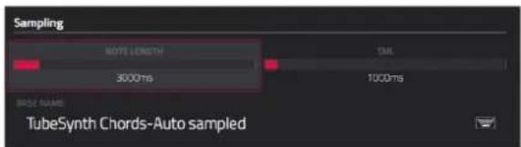
Use Base name to set the naming convention for the samples that will be created by the Auto Sampler.
Looping
Use the Enable looping field to select how the resulting samples can or cannot be looped:
• Off: The sample will not loop.
- Forward: You can hold down the pad to cause that sample to repeat from the Loop Position to the end of the sample. Release the pad to stop the repeating playback.
- Reverse: You can hold down the pad to cause that sample to play in reverse, repeating from the end of the sample to the Loop Position. Release the pad to stop the repeating playback.
- Alternating: You can hold down the pad to cause that sample to play from the Loop Position to the end of the sample and then play in reverse until it reaches the Loop Position again. This will repeat as long as you are holding the pad down. Release the pad to stop the repeating playback.

Use the Loop start and Loop end sliders to set the starting and ending points in the sample where the loop will occur.
Use the Crossfade slider to set the amount of crossfade between the loop end and loop start in seconds.
Use the Crossfade Type field to select Equal Power or Linear crossfade.
Under On completion, check Make current track to load the completed sampler patch as the current track.
Under Info, the Session Duration field provides an estimate of how long the auto sampling process will take.

Q-Link Edit

Q-Link Edit mode allows you to create and manage macro assignments. Macros can be used to control multiple automation parameters across different modes using a single Q-Link knob for expanded expressive performances. You can also map automation parameters to the XY Pad interface using this mode.
To enter Q-Link Edit Mode, press Menu and then tap Q-Link Edit.
You can also press and hold the Q-Link button on your MPC hardware (or any Q-Link Mode button on MPC X/X SE) to open the Q-Link window. From here, tap Q-Link Edit at the bottom of the screen to open Q-Link Edit Mode.
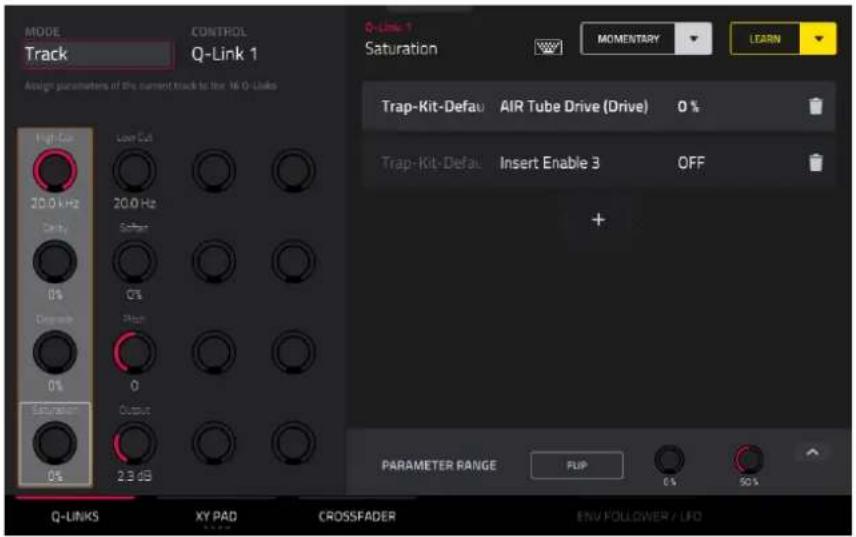
Use the tabs at the bottom of the screen to select a control to assign parameters to:
Q-Links
XY Pad
Crossfader
Click on the links above to jump to that section.
Note: For users with the MPC Pro Pack, a fourth mode—Envelope Follower / LFO—is also available. This tab will be greyed out when MPC Pro Pack is not activated. For more information on this mode, see the Addenda > MPC Pro Pack > Q-Link Edit – Envelope Follower / LFO.
On the left side of the screen, use the Mode field to switch between the different modes for each control. Some Modes cannot be edited using Macros mode, but you can view their assignments here.
Use the Control field to select or view the active control for editing.
The right side of the screen shows the parameters assigned to the selected controls, and the tools for adding and editing these parameters.
Learning Macro Assignments


To learn parameters to a Macro control in user assignable modes:
- Select a control type by tapping one of the buttons at the bottom of the screen: Q-Links, XY Pad, or Crossfader. See the following sections for more information on either control type.
- If available, select the desired mode for the control by using the Mode field at the top of the screen. See each following section for explanation of the available modes for each control in Q-Link Edit mode.
- Use the Control field to select the control to learn parameters to. In some modes like Q-Links, you can also directly tap to select the control below this field or move the desired control.
- When one of these editable modes is selected, the yellow Learn button and the learn add (+) button will appear on the screen.
To learn a single parameter to the control, tap the yellow Learn button so it is highlighted.
- Next, navigate to the mode that displays the parameter you would like to learn, and then adjust that parameter. The screen will show a message, "Learned [parameter] to [Q-Link]."
- To lock in the assignment, return to Q-Link Edit mode and tap the yellow Learn button again. The assigned parameters will be shown when the macro control is selected.
To learn multiple parameters to a macro, simply navigate to more parameters while Learn is engaged (step 4).
To learn another parameter to a macro that replaces the previous parameter, tap the down arrow next to the yellow Learn button, and then uncheck the Add box. Repeat the steps above to replace the previously learned parameter with a new one.
To learn a new parameter while also setting it to a range of values, tap the down arrow next to the yellow Learn button, and then check the Range box. While Learn is engaged (step 4 above), adjust the parameter to the low and high points of the value range that you want to control. When the assignment is locked in, the macro will control the parameter in the set value range.
To use a single macro to, for example, mute/unmute multiple tracks at the same time, tap the down arrow next to the yellow Learn button, and then check the Toggle box. Repeat the steps above to learn a parameter, which will toggle on/off when the control is touched or moved.
To use a macro to send the max value of a parameter, tap the down arrow next to the yellow Learn button, and then check the Trigger box. Repeat the steps above to learn a parameter, which will send its maximum value when the control is touched or moved.
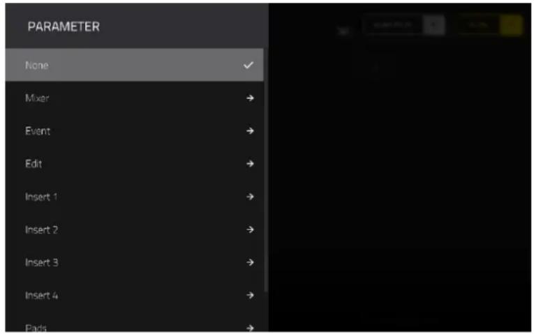
Alternatively, you can add parameters by tapping the learn add (+) button, and then using the menu that appears to select a parameter from your project. The following parameters are available, depending on the selected Mode and the tracks in your project:
When an Audio Track is selected:
Mixer: Volume, Pan, Mute, Solo, Send 1–4
Event: Mute
Insert 1–4: Available parameters depending on the effect
When a Drum Track is selected, and Parameter is set to Track:
Mixer: Volume, Pan, Mute, Solo, Send 1–4
Event: Mute
Edit: Global Semi Tune, Global Fine Tune
Insert 1–4: Off, other available parameters depending on the effect
When a Drum Track is selected, and Parameter is set to Pad:
Mixer: Pan, Level, Send 1–4, Pad Mute, Pad Solo
Edit:
| Pad X Position | Pitch Env Decay | LFO to Pitch | Decay Random |
| Pad Y Position | Pitch Env Sustain | LFO to Filter | Cutoff Random |
| Tuning | Pitch Env Release | LFO to Amp | Resonance Random |
| Filter Cutoff | Pitch Env Decay Mode | LFO to Pan | Total Random Amount |
| Filter Resonance | Pitch Env Attack Curve | LFO Wave | LFO Level (1–2) |
| Filter Env Amount | Pitch Env Release Curve | LFO Rate | LFO Delay (1–2) |
| Amp Env Attack | Pitch Env Depth | LFO Sync | LFO Fade In (1–2) |
| Amp Env Decay | Pitch Env Type | Velocity to Pitch | LFO 2 Wave |
| Amp Env Release | Ramp 1 Time | Velocity to Amp Attack | LFO 2 Rate |
| Amp Env Hold | Ramp 2 Time | Velocity to Amp | LFO 2 Sync |
| Amp Env Sustain | Note Counter 1 Size | Velocity to Pan | LFO 2 Reset |
| Filter Env Attack | Note Counter 2 Size | Velocity to Start | Global Drift Speed |
| Filter Env Hold | Layer Play Offset (1–8) | Layer Slice (1–8) | Voice Drift Speed |
| Filter Env Decay | Velocity Scaling | Layer Reverse (1–8) | LFO Delay Sync (1–2) |
| Filter Env Sustain | DrumFX (1–8) | Layer Offset (1–8) | LFO Fade In Sync (1–2) |
| Filter Env Release | DrumFX Type(1–8) | Layer Loop Xfade (1–8) | Layer Crossfade Mode |
| Amp Env Attack Curve | Layer Level (1–8) | Layer Loop Xfade Type (1–8) | Layer Crossfade X/Y |
| Amp Env Decay Curve | Layer Sample Pan (1–8) | Layer Slice Tail Length (1–8) | Articulation Speed (1–4) |
| Amp Env Release Curve | Layer Semi Tune (1–8) | Layer Slice Tail Start (1–8) | Articulation Dynamics (1–4) |
| Filter Env Attack Curve | Layer Fine Tune (1–8) | Layer Pitch Random (1–8) | Articulation Stereo (1–4) |
| Filter Env Decay Curve | Vel to Filter Attack | Layer Level Random (1–8) | Articulation Speed Scale (1–4) |
| Filter Env Release Curve | Velocity to Filter Depth | Layer Pan Random (1–8) | |
| Pitch Env Attack | Vel to Filter Cutoff | Layer Offset Random (1–8) | |
| Pitch Env Hold | Filter Type | Attack Random |
Insert 1–4: Off, other available parameters depend on the effect
When a Keygroup Track is selected, and Parameter is set to Track:
Mixer: Volume, Pan, Mute, Solo, Send 1–4
Event: Mute
Edit: Global Semi Tune, Global Fine Tune
Insert 1–4: Available parameters depending on the effect
When a Keygroup Track is selected, and Parameter is set to Keygroup:
Mixer: Pan, Level, Send 1–4, Pad Mute, Pad Solo
Edit:
| Tuning | Filter Env Attack Curve | Layer Fine Tune (1–8) | Layer Slice (1–8) |
| Filter Cutoff | Filter Env Decay Curve | Vel to Filter Attack | Layer Reverse (1–8) |
| Filter Resonance | Filter Env Release Curve | Velocity to Filter Depth | Layer Offset (1–8) |
| Filter Env Amount | Pitch Env Attack | Vel to Filter Cutoff | Layer Loop Xfade (1–8) |
| Amp Env Attack | Pitch Env Hold | Filter Type | Layer Loop Xfade Type (1–8) |
| Amp Env Decay | Pitch Env Decay | LFO to Pitch | Layer Slice Tail Length (1–8) |
| Amp Env Release | Pitch Env Sustain | LFO to Filter | Layer Slice Tail Start (1–8) |
| Amp Env Hold | Pitch Env Release | LFO to Amp | Layer Pitch Random (1–8) |
| Amp Env Sustain | Pitch Env Decay Mode | LFO to Pan | Layer Level Random (1–8) |
| Filter Env Attack | Pitch Env Attack Curve | LFO Wave | Layer Pan Random (1–8) |
| Filter Env Hold | Pitch Env Release Curve | LFO Rate | Layer Offset Random (1–8) |
| Filter Env Decay | Pitch Env Depth | LFO Sync | Attack Random |
| Filter Env Sustain | Pitch Env Type | Velocity to Pitch | Decay Random |
| Filter Env Release | Layer Play Offset (1–8) | Velocity to Amp Attack | Cutoff Random |
| Amp Env Attack Curve | Layer Level (1–8) | Velocity to Amp | Resonance Random |
| Amp Env Decay Curve | Layer Sample Pan (1–8) | Velocity to Pan | Total Random Amount |
| Amp Env Release Curve | Layer Semi Tune (1–8) | Velocity to Start |
Insert 1–4: Available parameters depending on the effect
When a Plugin Track is selected:
Mixer: Volume, Pan, Mute, Solo, Send 1–4
Event: Mute
Track: Available parameters depending on the plugin
Insert 1–4: Available parameters depending on the effect
When a MIDI Track is selected:
Event: Mute
Edit: Standard MIDI control change assignments
When a CV Track is selected:
Event: Mute
Edit: CV Out 1-4
When a Return is selected, the following options are available:
Mixer: Volume, Pan, Mute
Event: Mute
Insert 1–4: Available parameters depend on the effect
When a Submix is selected, the following options are available:
Mixer: Volume, Pan, Mute
Event: Mute
Insert 1–4: Available parameters depend on the effect
When a Main Output is selected, the following options are available:
Mixer: Volume, Pan, Mute
Event: Mute
Insert 1-4: Available parameters depend on the effect
To copy an existing macro assignment:
- Tap the learn add (+) button to open the parameter menu.
- Select Copy Existing Macro.
- To replace the current macro settings with the copied macro settings, select Replace.
- To merge the current macro settings with the copied macro settings, select Merge.
- Use the menu to select the existing macro you would like to copy.

Tap the Momentary button to turn momentary behavior on or off.
When on, moving the Q-Link will adjust its parameter, but the parameter will immediately return to its original position (when you turned Momentary on) when you release the Q-Link.
When off, moving the Q-Link will adjust its parameter, and the parameter will remain at its new setting when you release the Q-Link.
Tap the arrow next to the Momentary to adjust additional settings for when the macro control is released:
To revert the macro parameter(s) to its minimum value on release, check the Go to Minimum box.
To revert to the last value state before the macro was changed on release, check to Go to Previous box.
To rename a macro, tap the keyboard icon in the toolbar, and then use the keyboard to enter a new name.
Editing Macro Assignments
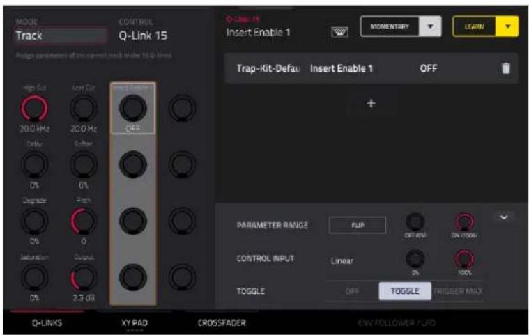
Above the Q-Link Edit control tabs on the right side of the touchscreen, the collapsible parameter inspector displays the settings for the currently selected learned parameter assignment. These settings can be edited for further customization of the macro.
To edit the parameters assigned to a macro:
- Tap the macro control on the left side of the screen, or touch or move the control on your MPC, to select it.
- Tap the learned parameter that you would like to adjust on the left side of the screen, so it is highlighted gray.
- Use the parameter inspector to view and adjust the settings for the assignment. Tap the arrow to view additional settings.
To reverse the polarity of the knob, tap the Flip button.
To adjust the minimum and maximum values sent by the knob, use the two Parameter Range knobs.
To set the response curve of the macro, use the Control Input field to select Linear, Logarithmic or Exponential. Use the knobs next to this field to set the percentage of the control that will be active.
To adjust the behavior of the macro, use the Toggle selector. When set to Off, moving the control sends a continuous range of values. When set to Toggle, moving the control toggles between the minimum and maximum values set above. When set to Trigger Max, moving the control always send the maximum value.
To remove a parameter assignment, tap the trash can icon. If all parameters are removed, the macro will no longer appear.
Q-Links
In this tab, you can view and/or edit Q-Link macro assignments, depending on the Mode selected.

To enter Q-Links mode, do either of the following:
• In Q-Link Edit Mode, tap the Q-Links button at the bottom of the screen.
- You can also press and hold the Q-Link button on your MPC hardware (or any Q-Link Mode button on MPC X/X SE) to open the Q-Link window. Then, tap Q-Link Edit at the bottom of the screen to open Q-Link Edit Mode.
To select a mode for the Q-Links, use the Mode field at the top of the display to select one of the following options:
Screen: In this mode, the Q-Links are fixed to control a parameter or group of parameters in your currently selected mode (e.g., Pad Mixer, Sample Edit Mode, etc.).

Project 1-2: In these edit modes, the Q-Link knobs can control 16 parameters within the current project overall.
Any available parameter, including Track, Pad, Keygroup, Insert, Return, Submix or Main Output parameters, can be selected as part of a macro control.
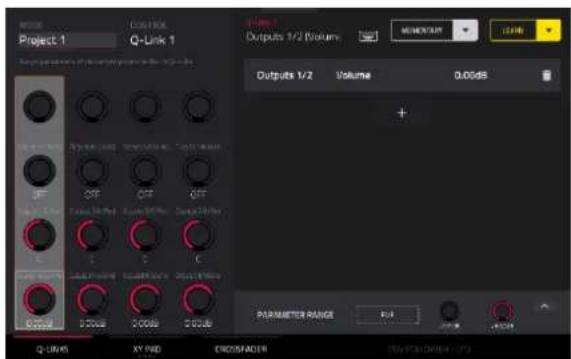
Track: In this edit mode, the Q-Link knobs can control 16 track parameters.
Only parameters for the current track, any Pads or Keygroups on the current track, or any Inserts on the current track can be selected as part of a macro control. This does not include Return, Submix or Main Output parameters.
Pad Scene: In this edit mode, the Q-Link knobs can control 16 parameters for the currently selected pad.
You can select another pad simply by pressing it, allowing you to adjust the same 16 parameters for that new pad. (These assignments are automatically saved with other user settings. Any project you load will use these assignments.)


Pad Parameter: In this edit mode, the Q-Link knobs control the same pad parameter for the each of the 16 pads in the current pad bank.
For example, if the Parameter is set to Level, the 16 Q-Link knobs will adjust the 16 independent Level settings for each pad in the current pad bank. You could then set the Parameter to Pan and use the Q-Link knobs to adjust the panning of all 16 pads.

Track FX Rack: In this edit mode, the Q-Link knobs can control 16 FX Rack parameters. The assignments can be saved as part of an FX Rack preset.
Only parameters available in the currently selected track's Insert effects can be selected as part of a macro control.
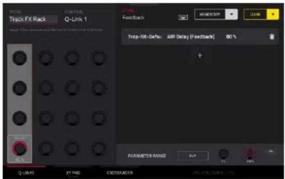
MIDI: In this mode, the Q-Links are fixed to a selection of MIDI performance controls, allowing you to control modulation, pitch bend, sustain and other common MIDI messages as you play.

Volume: In this mode, the Q-Links are fixed to controlling the volume level of the available tracks.

Pan: In this mode, the Q-Links are fixed to controlling the stereo panning of the available tracks.

Send 1-4: In these modes, the Q-Links are fixed to controlling each Send control on the available tracks.
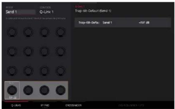
At any time, in any mode, you can show the Q-Links window over the screen's current contents. This lets you quickly select between the knob modes.
To show the Q-Links window, press and hold the Q-Link button. On MPC X/X SE, press and hold any of the Q-Link Mode buttons (Project, Program, Pad Scene, Pad Param, or Screen Control).
Tap the respective icon to select a Q-Link mode: Volume, Pan, Send 1–4, Project 1–2, Track, Track FX Rack, Pad Scene, Pad Parameter, MIDI, or Screen.
Tap Q-Link Edit at the bottom of the window to open Q-Link Edit mode.
Tap the Q-Link Status button to enable or disable the pop-up showing the current Q-Link assignments and values when Q-Links are touched. This can also be adjusted in the Preferences > General menu.
To close the Q-Links window, release the Q-Link button.

XY Pad
In the XY Pad tab, you can learn any automation parameter from within your project to one of four assignable XY Pads.
To cycle between the four available XY Pad assignments, tap the XY Pad tab.

Use the Control field at the top left of the touchscreen to select the part of the XY Pad that you would like to assign parameters to. This functions like a collection of different macros, allowing you to assign parameters to the X-Axis, Y-Axis, Columns 1–8, Rows 1–8, or even different to the axes of the Quadrants in the XY Pad.

Use the Full Screen button to make the current XY Pad fill the entire screen.
To learn a parameter to the XY Pad, follow the directions above.
Crossfader
In the Crossfader tab, you can learn any automation parameter from within your project to the Crossfader mode of MPC Key 61/37's Touch Strip.

There are 16 available crossfader scenes, which can be selected using the Control field at the top left of the screen. Each scene can be assigned to one or more parameters.
To learn a parameter to the crossfader:
- Make sure your MPC hardware is not currently in playback.
- Select the parameter you would like to assign to the crossfader using the directions above. Any available parameter, including Track, Pad, Keygroup, Insert, Return, Submix or Main Output parameters, can be selected as part of a macro control.
- Tap the A or B crossfader side to select a crossfader side. When A is selected, the parameter will be assigned to the crossfader with the minimum value to the left side and the maximum value to the right side. When B is selected, the parameter will be reversed with the maximum value on the left side and the minimum value on the right side.
Next Sequence Mode
Next Sequence Mode lets you trigger different sequences simply by playing the pads. This is useful for live performances, letting you change a song's structure in real time.
To enter Next Sequence Mode, do either of the following:
- Press Menu, and then tap Next Sequence.
- Press Next Seq (MPC X, MPC Live II, MPC One).

The Time Counter in the upper-right corner the current playhead position.
The sequence playlist on the left side shows a list-style overview of all used sequences in your project:
The Sequence column shows the name of the song's sequences.
The Length column shows the bar length of a sequence.
The BPM column shows the tempo of a sequence in beats per minute.
The currently selected sequence is highlighted in the list. Tap a sequence in the list to select it.

In Next Sequence Mode, every pad is assigned to a sequence, starting from Pad A01 with Sequence 1, and ascending from there. The pads will show the names of their corresponding sequences. Empty pads correspond to unused sequences. The currently selected pad will flash green.
During playback, change the next sequence that will play by pressing the corresponding pad or tapping it on the screen. If you do not select another sequence, the current sequence will repeat indefinitely.
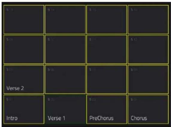
As a sequence plays, you can use the buttons at the bottom of the screen to change how playback works:
Tap Next Bar to switch to the currently selected sequence at the beginning of the next bar. This is useful if you want to switch to another sequence before the current one ends without having to worry about timing issues.
Tap Sudden to switch to the currently selected sequence immediately. The new sequence will start playing whether or not the current sequence is done. This is useful in live performances if you need to switch to the next sequence instantly at a certain cue.
Tap Clear to delete the currently selected sequence from the sequence playlist. This option is available only if that sequence is not playing at that moment.
Tap Hold to repeat the current sequence indefinitely and temporarily ignore pad presses. This is useful if you want to select other pads without selecting them to play next. Tap Hold again to return to normal operation.

To copy the sequence playlist to a song, tap Song while playback is stopped.
In the Copy to Song screen that appears, select a song, and then tap Do It to continue or Close to cancel.
To read more about Song Mode, please see the Song Mode chapter.
MIDI Learn
You can use the MIDI Learn function to assign external MIDI controllers to various parameters in your specific MPC project:
- Mixer parameters such as volume, pan, mute, and solo for tracks, returns, submixes, and main outputs.
- Pad parameters (for drum tracks only) such as tuning, filter and amp envelopes, layer settings, LFO settings, and velocity.
- Track parameters, which depend on the track type.
- Insert effects parameters, which depend on the effect type.
These assignments will be saved with your MPC project.
To enter MIDI Learn Mode, press Menu, and then tap MIDI Learn.

Each assignment has the following settings:
Source: This is the name or number of the track, return, submix, or main output.
Target: This is the name of the assigned command or parameter.
Type: This is the type of message:
- Toggle Button: When the control is a button, pressing it will activate or deactivate its command or parameter. It will remain in that state until you press it again.
- Momentary Button: When the control is a button, pressing and holding it down will activate its command or parameter. Releasing the button will deactivate it.
- Fixed Button: When the control is a button, pressing it will send its command.
• Note: When the control is a button, pressing it will send the MIDI note (determined by the Data field). - Abs CC: When the control is a knob, turning it will send its CC message (determined by the Data field) according to the precise physical position of the knob. (When you start turning it, the value may "jump" from its current value to the one corresponding to the knob's position.) This is for use with knobs that have a maximum and minimum position.
- Rel CC Offset: When the control is a knob, turning it will send the CC message (determined by the Data field), starting from the current value. This is for use with 360° knobs controlling parameters that have a maximum and minimum position.
- Rel CC 2's Complement: When the control is a knob, turning it will send the CC message (determined by the Data field), starting from the current value. This is for use with 360^ knobs controlling bipolar parameters where there is a center (12:00) position (e.g., panning).
Type is automatically detected based on the Source and Target fields, though you can use this field to assign it manually if it does not detect it properly.
Ch: This is the MIDI channel the control is using.
Data: This is the MIDI note number or CC number.
Flip: Tap this box to select or deselect it. When selected, the control's polarity will be reversed (e.g., a button's "off" state will become its "on" state and vice versa).
To assign a parameter to a hardware control:
- Tap Learn in the upper-right corner so it is on.
- Tap + on the left side of the touchscreen to create an “empty” assignment (its Target menus will be set to None and Off).
Alternatively, tap an assignment that is already in the list if you want to change it.
- Move or press the desired control on your MIDI controller. The Type, Ch, and Data fields will be automatically assigned.
- Use the Source field to select a track, return, submix, or main output (for drum tracks, you can select the entire track or a single pad within it). The Target menu will indicate the source you selected.
- Use the Target menu to select the parameter. Your selection will be shown under Target in the list, as well.
The control on your MIDI controller will now control the Target parameter.
To assign more controls, repeat Steps 2–5.
To stop assigning controls, tap Learn again so it turns off.
To clear an assignment, tap it in the list, and then tap Clear in the bottom-left corner. Alternatively, follow the steps above to reassign its Source field to None and assign its Target field to Off.
To clear all assignments, tap Clear All in the upper-right corner.
To delete an assignment (the entire slot), tap it in the list, and then tap Delete in the lower-right corner.
Live Control Mode
Your MPC hardware is pre-mapped to control Ableton Live 10.1.2 or later for instant performance and production setup, providing an unparalleled level of integration with Ableton Live from a standalone device. MPC's Control Mode has been carefully designed to allow you to instantly switch between using MPC in standalone mode and Live Control mode without ever stopping playback. You can control Ableton Live over a Wi-Fi network for cableless operation, or connect standalone MPC X/X SE or MPC Live/Live II to your computer using a USB-to-Ethernet adapter for a more tightly controlled setup.
To get started with Ableton Live Control, you will need to follow the directions in the sections below to download, install and configure the necessary and software.
Note: Live Control Mode is not available with MPC Key 37 and MPC Key 61.
Setup
Akai Network Driver
The Akai Network Driver will allow your MPC to seamlessly communicate with and control Ableton Live.
- Download the Akai Network Driver from your account at akaipro.com or using the inMusic Software Center, and install it by following the directions.
- Once the installation has completed, restart your computer.
- Power on your MPC.
- Press Menu and tap the gear icon to open the Preferences menu.
- Tap Wi-Fi to open the Wi-Fi settings. Make sure Wi-Fi is set to On, and then connect to your local wireless network. Alternatively, you can connect MPC to your network using a USB-to-Ethernet adapter. In this case, select Ethernet from the Preferences menu and make sure the Enabled option is checked.
- Open the Akai Network Driver application.
- In the Configured Remote Device field, locate the IP address and Serial Number of your MPC and select it. If you need to verify you are selecting the correct unit, you can view network information on your MPC in the Wi-Fi menu by holding Shift and tapping Info.
- If you still do not see your unit's Serial Number and IP, click the Add a Device button to manually enter your unit's IP address.
- Once your unit has been successfully configured, you can rename it by pressing the Rename a Selected Device button. When you are finished, you can close the Akai Network Driver application and open Ableton Live.
Configuring Ableton Live
- Important: To use MPC to control Ableton Live, you will need to download and install version 10.1.2 or later.
- Open Ableton Live 10.1.2 or later.
- Open the Preferences menu by selecting Live > Preferences.
- Make sure you have selected your preferred Audio Device in the Audio tab.
- In the Link / MIDI tab, click the first available Control Surface field and select Akai Force MPC.
- In the same row, select Akai Network – DAW Control as the Input and Output.
- Under the MIDI Ports section, set Remote for the Akai_Force_MPC Input and Akai_Force_MPC Output to On.
Once the previous steps have been completed, you can begin controlling Ableton Live with your MPC.
To open Live Control mode, press Menu (or tap the icon in the upper-left corner of the screen) on your standalone MPC hardware and then tap Live Control.
To exit Live Control mode, press Menu (or tap the icon in the upper-left corner of the screen) on your standalone MPC hardware and then select another mode.

Live Control Mode consists of three main views, which can be selected by tapping the tabs on the left side of the display: Matrix View, Mixer View, and Device Control View. Click the links to jump to that section.
In each of these modes, you will always have access to the following controls and functions on the display:
Tap a track name to select it.
Tap the stop icons at the bottom of the display to stop clips in the selected track.
Tap the Launch Quantize field (above the scene launch arrows) to set the Launch Quantize value.
Tap the Scene Launch arrows on the right side of the display to launch all clips in that row.
Additionally, MPC's hardware controls are pre-mapped to give you hands-on control of parameters and functions. See Appendix > Ableton Control Maps for the complete mappings.
Control Bar

At the top of the interface is the Control Bar. This toolbar can be configured to one of three presets based on typical Ableton Live use cases in the Settings window.
To open the Settings window, tap the gear icon in the top-right corner of the display.
Use the Control Bar field to select one of the three preset configurations: Settings, Arrangement or Performance.
- Session: The Session View configuration is ideal for working in Ableton Live's 8x8 clip launch matrix.
Use the BPM field to adjust the tempo in Ableton Live.
Tap the Phase Nudge Down and Phase Nudge Up icons to temporarily decrease or increase the tempo in Ableton Live.
Tap the metronome icon to enable to disable the metronome in Ableton Live.
Tap the follow icon to turn following on or off. When set to on, your Ableton Live software display will move along with playback to keep the current playback position in view. You can adjust the Follow Behavior in Ableton Live's Preferences.
Use the Position field to select the playback position.
Tap the + icon to enable or disable MIDI Arrangement Overdubbing.
Tap the automation icon to enable to disable automation recording.
- Arrangement: The Arrangement configuration is ideal for working with Ableton Live's linear Arrangement view.
Use the BPM field to adjust the tempo in Ableton Live.
Use the Position field to select the playback position.
Use the Start field to select the Arrangement loop start point.
Tap the loop icon to enable or disable Arrangement looping.
Use the Length field to select the Arrangement loop length.
• Performance: The Performance configuration is ideal for real-time performance with Ableton Live.
Use the BPM field to adjust the tempo in Ableton Live.
Tap the Phase Nudge Down and Phase Nudge Up icons to temporarily decrease or increase the tempo in Ableton Live.
Use the Quantize To field to set the time division for quantization: 1/4, 1/8, 1/8T, 1/8 and 1/8T, 1/16, 1/16T, 1/16 and 1/16T or 1/32.
Matrix View

The Matrix View provides an overview of the clip matrix from Ableton Live's Session view, displaying up to eight tracks and eight rows of clips on the display. The tracks and clips displayed on your MPC's touchscreen will be shown in Ableton Live with a colored box outline.
All tracks, clips and scenes will display the same color and names as assigned in Ableton Live. The pads on your MPC hardware will also change color depending on the playback or recording state:
When a clip is stopped, it will display the color set in Ableton Live on both the hardware pads and display.
When a clip is playing, the hardware pad will blink green, and the clip on the display will fill with white based on the clip length.
When a clip is preparing to record, it will flash red on both the hardware pads and display until the launch quantization value is reached.
When a clip is recording, it will blink red on the hardware pads and be lit red on the display.
You can also access the following controls and features by tapping the buttons at the bottom of the display:
Tap Quantize at the bottom of the screen to quantize the currently selected clip according to the Quantize To value (set in the Ableton Live Control Settings).
Tap Delete at the bottom of the screen to delete the currently selected clip.
Tap Insert Scene at the bottom of the screen to insert a new scene after the currently selected clip.
Tap Rec at the bottom of the screen to enable or disable Ableton Live's Arrangement Record. Use this to capture your Session performance into the Arrangement view.
Mixer View

The Mixer View gives you control of Ableton Live's key mixing features, such as levels, stereo panning, sends and returns and more. Use the tabs at the bottom of the display to select what information is shown on MPC's display.
- Levels: The Levels tab gives you an overview of the volume level of your tracks, including the Returns and the Main Output track.
Tap a level slider and then use the data dial or - / + buttons to adjust the volume level of the currently selected track, return or main output. Alternatively, tap and drag a level slider to adjust the volume level.
The level sliders and meters in each pad show a visual representation of the level. Double-tap a track on the screen to open a large version of the level slider and meter.
- Main: The Main tab gives you a full channel strip with a number of mixing options for your tracks.
Tap the track activator (under the track name) to enable or disable (mute) the track.
Tap the S button to solo the track.
Tap the record button to arm the track for recording.
The pan sliders in each track show a visual representation of the pan. Tap a pan slider and then use the data dial or - / + buttons to adjust the panning of the currently selected track, return or main output. Alternatively, tap and drag the pan slider to adjust the panning. Double-tap a pan slider on the screen to open a large version of the slider.
Tap a level slider and then use the data dial or - / + buttons to adjust the volume of the currently selected track, return or main output. Double-tap a level slider on the screen to open a large version of the slider. Alternatively, tap and drag a level slider to adjust the volume level.
- Sends: The Sends tab gives you an overview of the Send and Return controls in Ableton Live.
Use the send knobs to adjust the send level of tracks. Tap the knob and use the data dial or - / + buttons to adjust the level. Alternatively, tap and drag the send knob to adjust the send level.
Tap the A or B icons to assign the track to the Ableton Live's A or B cue mix.
Device Control View

The Device Control View allows you to control MIDI Instruments, Audio Effects and other Devices in Ableton Live directly from your MPC. The current view of the Device Control Tab is determined by the "blue hand" remote control icon in Ableton Live's Detail View.
Tap the Track Name under the Control Bar to select the Track. If there is a Device(s) associated with the Track, the first will be shown below.
Tap the lock icon on the right side to lock parameter changes to the device.
Use the sliders to adjust the parameters of the device. Tap a slider and then use the data dial or - / + buttons to adjust the parameter. Alternatively, tap and drag a slider to adjust the parameter.
Use the Device - and + buttons to change devices on the same track. The white and grey boxes below the parameter sliders represent the number of available Devices.
Use the Bank - and + buttons to cycle through banks of controls for the device, if available. For internal Ableton Live plugins, you will see the name of the current bank. For third party plugins, you will see the number of the current bank.
Tap Device On to enable or disable (bypass) the device.
Q-Links
The Q-Links on your MPC give you hands-on control of Ableton Live's key parameters.
On MPC X/X SE, Q-Links 1–8 control track volume for the eight tracks currently in view, while Q-Links 9–16 control the device on the currently selected track, based on the "blue hand" in Ableton Live's Detail View. The OLED screens above each Q-Link also provide clear visual feedback of the parameter name and value being controlled.
On MPC Live/Live II, Q-Link Banks 1 and 2 control track volume, and Q-Link Banks 3 and 4 control the current device at the "blue hand" position. Press and hold the Q-Link button to bring up the Q-Links Overview on the touchscreen, where you can view the current assignments and quickly select another bank.
Song Mode
Song Mode lets you arrange sequences in a specific order and/or repetition to create songs. You can edit the structure of a song during playback for easy, on-the-fly composing.
A project can contain up to 32 songs, each consisting of up to 999 “steps.” Each step can have an assigned sequence as well as the number of times that sequence will repeat.
To open Song Mode, do either of the following:
- Press Menu, and then tap Song Mode.
- Press Shift and Next Seq/Song (MPC X).
Important: If a sequence is currently playing, stop playback before entering Song Mode. You cannot enter Song Mode during playback.
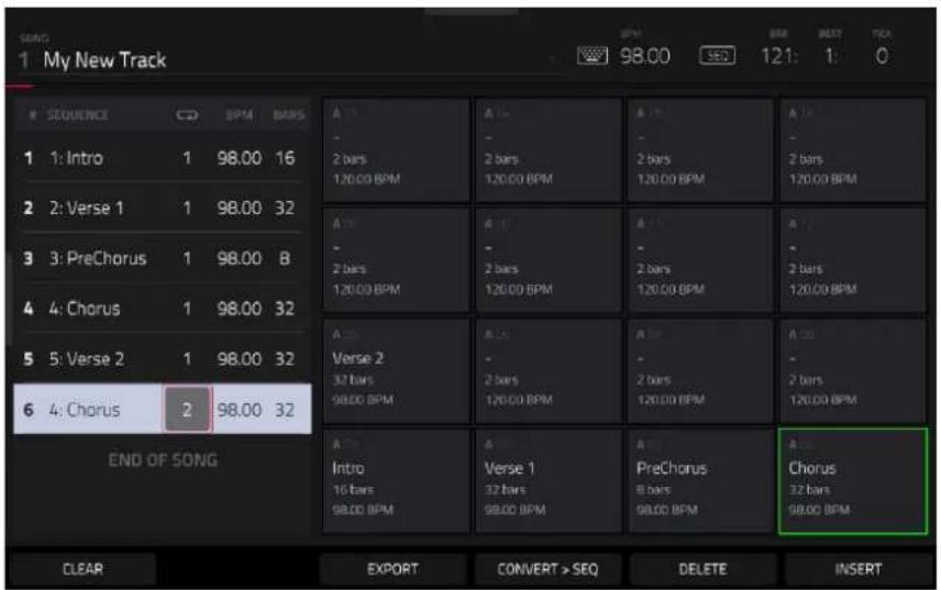
Use the Song field to select the song you want to show.
Tap the keyboard icon to rename the current song.
Use the BPM field to adjust the tempo of the sequence.
Tap the Seq/Gbl button to set whether the sequence follows its own tempo (Seq) or a global tempo (Gbl). Alternatively, press Shift and Tap/Master.


The Time Counter shows the current playhead position, in bars:beats:ticks.
The sequence playlist on the left lists of the "steps" of a song. Each step has (in columns, left to right):
• the step number (each song can contain up to 999 steps)
• a sequence number and name
- how many times the sequence plays (each step can play up to 999 times; set it to Hold [the lowest/minimum value] to set the sequence to repeat indefinitely until you stop playback)
• the tempo of the sequence
- the number of bars the step occupies (based on how many times it plays)

Each used sequence is assigned to a pad. Empty pads correspond to unused sequences. Use the Pad Bank buttons to access the sequences assigned to pads in other banks.

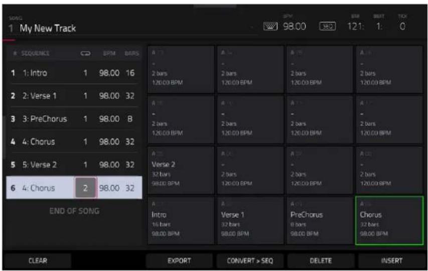
To insert a step:
- Tap a step in the sequence playlist after which you want to insert a step.
- Tap Insert in the lower-right corner of the screen.
Alternatively, "record" a song using the pads:
Note: The sequences or song will not play back as you use the pads to create your song in this way. Pressing the pads just enters their corresponding sequences as steps.
- Press Rec or Overdub to "record-arm" the song.
- Press or tap the pad that corresponds to the first sequence you want to use. That sequence will appear in the sequence playlist as the first step.
- Repeat Step 2 for each additional step you want to add to the sequence playlist. Press or tap a pad multiple times to add to the number of times it plays.
- Press Stop to stop "recording."

To change a step's sequence:
- In the desired step, tap the sequence name.
- Use the data dial or - / + buttons to select another sequence.
Tap Clear to erase the entire sequence playlist (delete all steps).
To delete a step, tap it, and then tap Delete in the lower-right corner of the screen.
Tap Next to switch to the next sequence at the beginning of the next bar during playback. This is useful if you want to switch to another sequence before the current one ends without having to worry about timing issues.
Tap Sudden to switch to the next sequence immediately during playback. The new sequence will start playing whether or not the current sequence is done. This is useful in live performances if you need to switch to the next sequence instantly at a certain cue.
To convert the current song to a single sequence:
- Tap Convert > Seq to open the Convert to Sequence window.
- Use the To Sequence field to select which sequence you want the song to export to.
- Use the Track Status field to select whether you want the song to Exclude Muted Tracks or Include Muted Tracks in the new sequence.
- Tap Do It to confirm your selections.
Tap Close to cancel the process.
Tap Export to open the Audio Mixdown screen, where you can render/export your song as an audio file.
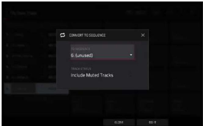
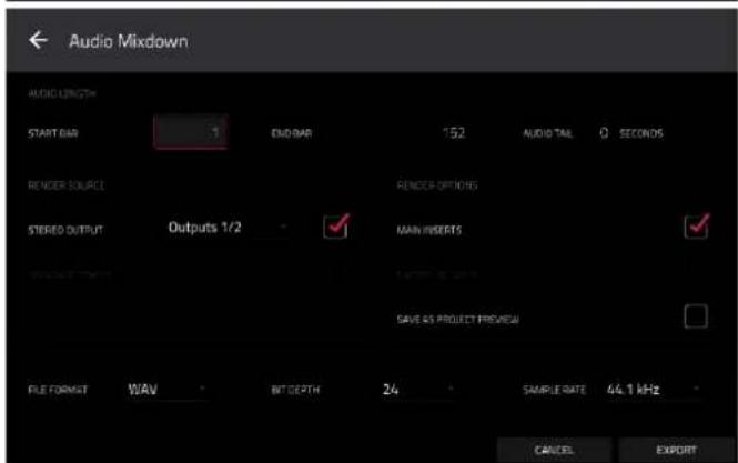
Key Ranges Mode

Key Ranges Mode gives you an overview of the MIDI tracks in your project. This mode includes functionality similar to Track View mode and Main Mode, but may be more useful when setting up a large external keyboard to control multiple instruments at the same time.
To open Key Ranges Mode, press Menu, and then navigate to Key Ranges on the second page of modes and tap it.

Tap the gear icon in the upper-right corner to open the Key Ranges Settings window. Here, you can adjust the Solo Behavior to be either Single (so only one track can be soloed at a time) or Multi (multiple tracks can be soloed at a time).
Use the Track field at the top of the screen to select a track. You can also tap a track bar under the keyboard to select it.
Use the Min and Max field to set the minimum MIDI note value and maximum MIDI note value for the track. You can also tap and drag along the edges of the track bar to resize the key range, or tap and drag from the middle of the track bar to move the entire range left or right.
Alternatively, tap the Learn Min or Learn Max buttons at the bottom of the screen, and then press a key on a connected keyboard to set that note as the minimum or maximum MIDI note value of the key range.
Tap New Track to add a new track.
Tap MIDI Filter to apply MIDI filtering to each track:
Use the Note Min and Note set the minimum MIDI note value and maximum MIDI note value for the track.
Use the Velocity Min and Velocity Max fields to set the range of incoming velocity for the track.
Use the MIDI CC Filter fields enable or disable certain MIDI CC messages from being input. Check a box to enable the selected message, or uncheck to filter it out.
Tap the Reset button to reset all MIDI Filter settings.
Tap Pads: Mute/Solo to cycle between track muting and soloing using the MPC hardware pads while in Key Ranges mode.
When using Track Soloing, tap the Clear Solos button to unsolo tracks that have been soloed.

To instantly adjust the key range for drum tracks, press and hold Shift and then tap Drum Split. This will automatically set the key range of Drum Tracks to the first 16 notes of the keyboard so that they correspond with Pads 1–16. This is useful for using the MPC Key 61 to play melodic sounds on the keypad and drum sounds on the pads at the same time.
Key Ranges mode also provides access to the same XL Channel Strips as seen in Main Mode. Tap the icons at the top of the condensed strips to show or hide the mixer channel strips.
MIDI Control Mode

You can use MIDI Control Mode on your MPC hardware to customize what MIDI messages are sent from certain controls on your hardware. This custom “control map” will then work whenever you are in MIDI Control Mode. The edits you make in MIDI Control Mode will be retained with the current MPC project.
This feature enables you to use your MPC hardware to control external MIDI devices connected to its MIDI out.
To enter MIDI Control Mode, do either of the following:
- Press Menu, and then navigate to MIDI Control on the second page of modes and tap it.
- Press Shift and Program Edit/MIDI Control (MPC One), or press Shift and Keyboard Control/MIDI Control (MPC Key 61, MPC Key 37).
Important:
In Standalone Mode: Make sure your MPC hardware is using the correct MIDI output. You can set this using the MIDI Output Port field at the top of the touchscreen, or in Preferences > MIDI / Sync.
In Controller Mode: In your host software, make sure your MPC hardware is selected as a MIDI controller device.

In the touchscreen, use the fields and selectors to set each control's parameters to your preference. The available parameters depend on its type: a pad, or button, a Q-Link knob, or each axis of the XY pad. When you have set all of the parameters as desired, you can select another control or enter another mode.
Use the MIDI Output Port field at the top of the touchscreen to set the MIDI port that the MPC hardware will send messages from. You can also set this in the MIDI / Sync section of the Preferences menu.
Tap the I/O buttons at the top of the touchscreen to open the MIDI Monitor.
To select a control to edit, do any of the following:
- Press or turn it. In the lower-left corner, tap the Hardware tab to edit a pad, button, or Q-Link knob, or tap the XY tab to edit the XY pad.
- Tap the Control field in the upper-left corner, and then turn the data dial to select one.
• Double-tap the Control field, and then tap a control name in the menu that appears.
Note: The Control field menu will show many more hardware controls than are actually available on your MPC hardware. This is because the list includes all possible controls from all current MPC models (MPC X, MPC Live, etc.). You can edit only the controls that are described in this chapter.
Note: The software window will also display a graphical interface resembling your MPC hardware. Editable controls show their current MIDI message. Pads and Q-Link knobs show their current MIDI channels.
Pads

These are the MIDI parameters you can edit for each pad:
Control: This is the hardware control you are currently editing (Pad 1–Pad 16).
Bank: This is the pad bank the pad belongs to. If you check the Set All box, the pad's messages and parameters will be identical across all eight banks.
Set All: When this box is checked, the pad's messages and parameters will be identical across all eight banks. When this box is unchecked, the pad's messages and parameters will apply to the current pad only.
Light LED: This determines how the pad's LEDs will behave.
When set to Never, the LEDs will always be off.
When set to MIDI Input, the LEDs will light up when the software receives a MIDI message that matches the pad.
When set to Local, the LEDs will light up when you press the pad and/or MIDI input is received.
MIDI Channel: This determines which MIDI channel (1–16) the pad will use to send its message to the software.
Note: This is the MIDI note number the pad will send to the software when you press it (0–127 or C-2 to G8).
Velocity: This determines whether the pad will be velocity-sensitive (On) or not (Off). When set to Off, pressing the pad will send a note at full-level (127) always.
Aftertouch: This determines how the pad's aftertouch (pressure applied to the pad after the initial press) behaves.
Off: The pad will not send any aftertouch messages.
Channel: If you press multiple pads that have this setting, the aftertouch messages they send will be identical.
Poly: If you press multiple pads, the aftertouch message each pad sends will be independent from the others.
Buttons
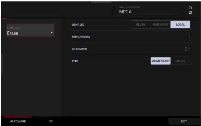
These are the MIDI parameters you can edit for each button. You can edit the Erase, Tap, Undo/Redo, or Copy/Delete buttons:
Control: This is the hardware control you are currently editing (Erase, Tap, Undo, or Copy).
Light LED: This determines how the button's LED (or multiple LEDs) will behave.
When set to Never, the LEDs will always be off.
When set to MIDI Input, the LEDs will light up when the software receives a MIDI message that matches the button.
When set to Local, the LEDs will light up when you press the button and/or MIDI input is received.
MIDI Channel: This determines which MIDI channel (1–16) the button will use to send its message to the software.
CC Number: This determines what MIDI Control Change number the button will send to the software.
Type: This determines whether the button will behave as a Momentary switch or Toggle (latching) switch.
Q-Link Knobs

These are the MIDI parameters you can edit for each Q-Link knob and the Touch Strip:
Control: This is the hardware control you are currently editing (Q-Link 1–16, Touch Strip).
Light LED: Although you can edit this parameter, it does not actually have a function on your MPC hardware.
When set to Never, the LEDs will always be off.
When set to MIDI Input, the LEDs will light up when the software receives a MIDI message that matches the Q-Link knob.
When set to Local, the LEDs will light up when you touch or turn the Q-Link knob and/or MIDI input is received.
MIDI Channel: This determines which MIDI channel (1–16) the Q-Link knob will use to send its message to the software.
CC Number: This determines what MIDI Control Change number the Q-Link knob will send to the software.
Mode: This determines how the Q-Link knob will control its parameter. This is not available when Touch Strip is selected.
Absolute: The Q-Link knob's current position determines its parameter's value; moving it may cause its parameter to "snap" to a new position if you're using it to control different parameters in different modes.
Relative: Moving the Q-Link knob will increase or decrease its parameter regardless of its physical position.
Low Range: This is the Q-Link knob or Touch Strip's lowest possible value (0–127).
High Range: This is the Q-Link knob or Touch Strip's highest possible value (0–127).
Touch Sense: This activates or deactivates the Q-Link knob or Touch Strip's touch-capacitive circuitry.
On: You can touch the Q-Link knob or Touch Strip to send a Note On message to the software (this is how your MPC hardware normally works).
Off: The Q-Link knob or Touch Strip will not send any Note On messages; it will only send CC messages when you turn it.
Note: This is the MIDI note number the Q-Link knob or Touch Strip will send to the software when you touch it (0-127 or C-2 to G8). Touch Sense must be set to On for this to work.
XY Pad
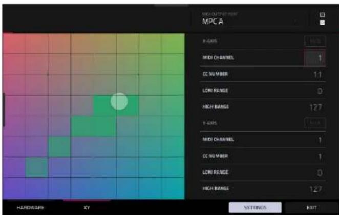

These are the MIDI parameters you can edit for each axis of the XY pad:
Control: This is the axis you are currently editing (XYFX X-Axis or XYFX Y-Axis). This field will be hidden if you tapped the XY tab to show the XY pad's parameters. You can tap the Hardware tab to show this field.
Mute: This button determines whether the axis is muted or not. When muted, its MIDI output is disabled. You must be viewing the Settings to do this.
MIDI Channel: This determines which MIDI channel (1–16) the axis will use to send its message to the software.
CC Number: This determines what MIDI Control Change number the axis will send to the software.
Low Range: This is the axis's lowest possible value (0–127).
High Range: This is the axis's highest possible value (0–127).
Pad Color Mode

Pad Color Mode lets you assign specific colors to your pads in a track.
To enter Pad Color Mode, press Menu, and then navigate to Pad Color on the second page of modes and tap it.
Use the Track field at the top of the screen to select the desired track. Keygroup, Plugin, MIDI, and CV tracks will use the Pad Perform mode pad color layout by default. To create a custom pad color layout for these tracks, tap the pad area on the screen after selecting the track. This will enable custom pad colors for all tracks using Pad Perform mode.
Use the Bank field to select the desired bank of pads in the current track.

Use the field in the lower-left corner to set how the pad lights will display:
• Off: The pads will be unlit whether you are playing them or not.
- Classic Velocity: The pads will be unlit while you are not playing them. When you press them, they will light with colors according to the velocity: red indicates a high velocity, yellow indicates a low velocity.
• Fixed: The pads will be lit with their assigned colors whether you are playing them or not.
- Off->Velocity: The pads will be unlit when you are not playing them. When you press them, they will light with their assigned color with a brightness that corresponds with the velocity.
- Dim->Velocity: The pads will be dimly lit when you are not playing them. When you press them, they will light with their assigned color with a brightness that corresponds with the velocity.
- Bright->Velocity: The pads will be brightly lit when you are not playing them. When you press them, they will light with their assigned color with a brightness that corresponds with the velocity.
Use the Empty Pads field in the upper-left corner to set how empty pads will display:
• Empty pads off: Pads without any sounds will remain off.
• Empty pads dim: Pads without any sounds will remain more dimly lit than pads with sounds assigned.
• Empty pads normal: Pads without any sounds will appear the same as pads with sounds assigned.
Use the Single Pad/All Pads select to determine whether you are setting the color for a Single Pad or All Pads.
Tip: To quickly assign that color to all pads in the track, press and hold Shift while tapping a color button.
Use the color buttons to select which color you are assigning.
Tip: To select the color button corresponding to a specific pad's color, press and hold Shift, and then press the pad or tap it on the screen.
Press a pad on your MPC hardware or tap it on the screen to assign the selected color to it.
Tap Make Default to make the current pad color settings the defaults for all tracks on the same type (e.g., drum tracks, keygroup tracks, etc.). In the window that appears, tap Do It to confirm your choice or Cancel to cancel.
Looper

The Looper lets you record and overdub audio in real time—a great tool for live performance as well as spontaneous moments in the studio. You can export the loop as a sample to use in your project.
To open the Looper, do either of the following:
- Press Menu and then navigate to Looper on the second page of modes and tap it.
• Press Shift and Sampler/Looper (MPC X, MPC One).

Below is a brief step-by-step process so you can get started quickly. Continue reading the rest of this chapter to learn how to use the Looper in different cases.
To get started using the Looper:
- Make sure to reduce the volume levels of your audio source and speakers/headphones/monitors before you make any connections to avoid "pops" or feedback.
- Connect your audio source to the input/inputs of your MPC hardware.
For line-level devices such as a synthesizer, set the Line/Inst switch to Line; for instrument-level devices such as a guitar, set the switch to Inst.
If you are using a microphone that requires phantom power, set the +48V switch to On.
- Turn the Gain knob to set the input level while playing your audio source. You should now see the level in the meter. Make sure it does not exceed the maximum level (the meter should not be "peaking" constantly).
- Set the recording controls as desired (described in this chapter).
- If the Sync button at the top of the screen is enabled, Looper recording will only be active during sequence playback. Tap it to disable transport sync, allowing you to freely record with the Looper.
- Tap the Record To selector so Overdub is selected.
- Tap the Rec/Record button in the lower-right corner to record-arm the Looper.
- Play your audio source. The Looper will start recording immediately when the input level reaches the threshold value. Alternatively, tap ▶/Play at the bottom of the screen to manually start recording.
Each time the Looper repeats, its contents are being overdubbed—a new layer of audio will be added each time you let the Looper repeat as it records.
Tip: You can record a loop while playing one or more tracks in the background for reference.
- Tap ▶/Play at the bottom of the screen to stop recording.
Tap Export to Track, or hold Shift and tap Export to Pad, to open the Keep or Discard Sample window and export your loop as a sample to a track or pad.
Tap Clear to clear the contents of the Looper.
The upper-left Input Source field defines whether you are going to record an external audio signal, which you can set to the pair of inputs (Input 1,2) or a single input (Input 1-2). You can also select an internal signal from within your MPC hardware (Resample L, Resample R, or Resample L+R).
Resampling does not require an audio connection because the source is internal and is therefore recorded without any loss in audio quality. You can, for example, use Resample to record two or more samples by pressing the corresponding pads simultaneously.
Use the second upper-left Mono/Stereo field to choose whether your recorded loop will be monaural (Mono) or binaural (Stereo).
The Inserts field shows any enabled or disabled effects for the Looper. Tap the area under Inserts to open a window where you can load, change, and enable or disable the effects.
Important: These effects are applied to the audio as you record it. This means that the effects cannot be “removed” from the sound later. Learn more about how effects work in General Features > Effects.

Tap the Monitor button to enable or disable input monitoring.
When set to In, the audio you hear in your headphones will be taken before it reaches the Looper, ensuring zero latency. You can turn input monitoring on only if the Input Source field is set to an input, not to a Resample setting.
When set to Off, the audio you hear in your headphones will be taken after it is processed in the Looper, so there may be some latency, but you will hear the audio source as it sounds in the recording.
Tip: To avoid possible clicks or feedback while input monitoring, reduce the level of the audio sources.
Use the threshold slider to adjust the threshold. Alternatively, turn Knob 1 when the knobs are set to screen mode. The threshold slider will work only when Sync is off (see below).
When the Looper is record-armed, it automatically starts recording when the level of the incoming source exceeds this setting. If you set it too high, the recording may not start when you play the input source, or the start of the material you wanted to record may be missing. If you set it too low, the recording may start too early, before you play the external source. Set this parameter to an appropriate level using the level meter.
To reset the “peak hold,” which shows the highest level of your input signal in the level meter, tap it.
Use the Bars field to define the length of your loop. Regardless of how much or how little audio you record, this is how long your loop will be.

Use the Sync button to sync or un-sync the looper with transport playback. When on, the Looper will stay in step with your project. When you play or record into the Looper, it will wait until the transport starts playing to start.
Use the Record To selector to determine the loop recording behavior:
- Play: Before recording, you must first tap the ▶/Play button on the screen, which will start playing the Looper.
- Overdub: Before recording, you must first tap the Rec/Record button in the lower-right corner to record-arm the Looper.
Use the Output Gain slider to set the output signal level of the Looper.
To record with the Looper:
Important:
To record without erasing any audio you've already recorded in the loop, use the Overdub button.
To overwrite the audio you've already recorded, use the Replace button.

If Record To is set to Play:
To start recording, tap the Replace or Overdub button as the loop is playing. The Looper will start recording immediately.
To stop recording, tap the Replace or Overdub button. The Looper will stop recording but continue playing.
To stop playback and recording, tap the ▶/Play button.
If Record To is set to Overdub:
To start recording, tap the ▶/Play button on the screen.
If Sync is off, you can also play your audio source so that the input level reaches the threshold value.
If Sync is on, you can also press the Play or Play Start button to start transport playback; recording will start when the transport starts playing.
To stop recording, tap Overdub. The Looper will stop recording but continue playing.
To stop playback and recording, tap the ▶/Play button, or press Stop to stop transport playback.
To play or stop the loop (without recording), tap the ▶/Play button on the screen.
To reverse loop playback, tap Reverse. If Sync is on, playback will reverse once the Looper's playhead reaches the end of the loop. If Sync is off, playback will reverse immediately.
To erase the loop immediately, tap Clear.
To export the loop to an audio track:
- Tap Export to Track to open the Looper Export window.
- Use the Audio Track field to select the audio track you would like to export the sample to.
- Tap Export to Track to confirm your choice, or Cancel to cancel.
When your loop is done exporting, it is assigned to the track you selected.

To export the loop to a pad:
- Press and hold Shift and tap Export to Pad at the bottom of the screen to open the Keep or Discard Sample window.
- Use the Track field to assign the new sample to a track. Select
if you want to save it to the project without assigning it to a track. You can also tap Save at the bottom of the screen to save the sample to the general sample pool.
Use the Assign to Pad field to assign the sample to a pad in the track.
Use the Root Note field to set where the sample's original pitch will be on the keyboard.

If you recorded a sample while a sequence was playing, the Keep or Discard Sample window will show a few more options after you select a pad:
Check the Add Event box to automatically add the sample to the currently playing sequence.
Use the At field to select where you want the event to start:
• Start: The sample will be a note event at the start of the currently playing sequence.
- Trigger: The sample will be a note event where you began recording it in the currently playing sequence.
- Tap Keep at the bottom of the screen to confirm your selections.
Tap Discard at the bottom of the screen to discard the recording and return to the Sampler.
Tap Play at the bottom of the screen to play the recording.
Tap Edit to save the sample and open Sample Edit Mode to edit your recorded sample.
Hardware Features
This chapter explains the features and functions of each MPC v3.6-supported model: MPC X / MPC X Special Edition, MPC Live, MPC Live II, MPC One / MPC One+, MPC Key 61, and MPC Key 37.
MPC X / MPC X Special Edition
Note: Mentions of the features and functions of MPC X hardware throughout this guide also apply to the MPC X Special Edition unless otherwise noted.
Top Panel

Navigation & Data Entry Controls
- Touchscreen: This full-color multi-touch display shows information relevant to MPC X's current operation. Touch the touchscreen (and use the hardware controls) to control the MPC interface.
Tip: If you adjust the angle of the touchscreen, use the stand on its back panel to secure it in place.
- Cursors: Press these buttons to navigate through the fields of menus and options shown on the screen.
Press and hold Shift and press these buttons to zoom in or out of the Grid View or Audio Edit Mode. Press and hold Shift and press the up and down cursors simultaneously or the left and right cursors simultaneously to return to the default zoom setting.
-
Data Dial: Use this dial to scroll through the available menu options or adjust the parameter values of the selected field on the screen.
-
-/+ : Press these buttons to increase or decrease the value of the selected field on the screen.
-
Numeric Keypad: If the selected field on the screen is a number, press these numbered buttons as you would on a standard numeric keypad to enter a value. Press the keypad's Enter to enter it. (A numeric keypad with additional operations will appear on the screen, as well.)
-
Undo/Redo: Press this button to undo your last action.
Press and hold Shift and press this button to redo the last action you undid.
- Shift: Press and hold this button to access some buttons' secondary functions (indicated by red writing).
Double-press this button to see which buttons have secondary functions—the buttons will flash for a few seconds.
- F-Key: Press this button to activate or deactivate the F-Key feature. When active, the six buttons under the touchscreen correspond to the options shown at the bottom edge of the screen. The F-Key button and those six buttons will be lit red when active. When inactive, the six buttons under the touchscreen will access their normal modes instead (Menu, Browser, Step Seq, Sampler, XYFX, and Looper).
Pad & Q-Link Controls
-
Q-Link Knobs: Turn these touch-sensitive knobs to adjust various parameters and settings. The display strip above each knob indicates the parameter it is controlling. If the display strip shows a meter to indicate its value, you can touch or turn its Q-Link knob to temporarily show its precise numerical value.
-
Pads: Press these pads to trigger drum hits or other samples in your software. The pads are velocity-sensitive and pressure-sensitive, which makes them very responsive and intuitive to play. The pads will light up different colors, depending on how hard you play them (ranging from yellow at a low velocity to red at the highest velocity). You can also customize their colors.
-
Pad Bank: Press these buttons to access Pad Banks A–D.
Press and hold Shift while pressing these buttons to access Pad Banks E-H. Alternatively, double-press one of these buttons.
- Copy/Delete: Press this button to copy one pad to another. When the From Pad field is selected, press the "source" pad (the pad you want to copy). When the To Pad graphic (of all pads) is selected, press the "destination" pad. You can select multiple destination pads, and you can select pads in different pad banks. Tap Do It to continue or Close to return to the previous screen.
Tip: To quickly copy a pad, press and hold Copy, press the source pad, press the destination pad, and then release Copy.
Press and hold Shift and press this button to delete a pad's sample assignment. When the Delete Pad window is shown, press any pad/pads whose sample assignments you want to clear. Tap Delete to continue or Cancel to return to the previous screen.
- Full Level/Half Level: Press this button to activate or deactivate the Full Level feature. When activated, the pads will always trigger their samples at the maximum velocity (127), regardless of how much force you use.
Press and hold Shift and then press this button to activate or deactivate the Half Level feature. When activated, the pads will always trigger their samples at half-velocity (64).
Press and hold this button to set a custom user level velocity that can be used in place of Half Level.
- 16 Level / Pad Perform: Press this button to activate/deactivate 16 Level. When activated, the last pad that was hit will be temporarily copied to all 16 pads. The pads will now output the same note number as the initial pad, but a selectable parameter will be fixed at values that increase as the pad numbers increase (e.g., Pad 1 is the minimum, Pad 16 is the maximum), regardless of how hard you press them. In the screen that appears, use the Type selector to choose the parameter: Velocity, Tune, Filter, Layer, Attack or Decay. See Operation > General Features > 16 Level to learn more.
Press and hold Shift and press this button to enter Pad Perform mode for the pads. When activated, you can play musical scales/modes, chords or progressions using the pads while in any mode. See Operation > General Features > Pad Perform to learn more.
- Note Repeat/Latch: Press and hold this button, and then press a pad to trigger that pad's sample repeatedly. The rate is based on the current tempo and Timing Correct settings.
Press and hold Shift and then press this button to "latch" the Note Repeat feature. When latched, you do not have to hold the Note Repeat button for it to be activated. Press Note Repeat once more to unlatch it.
-
Project: Press this button to use the Q-Link knobs to adjust parameters related to the current project. Press and hold Shift and then press this button to enter the Project Q-Link Edit Mode directly.
-
Program: Press this button to use the Q-Link knobs to adjust parameters of the currently selected track or audio track. Press and hold Shift and then press this button to enter the Track Q-Link Edit Mode directly.
-
Pad Scene: Press this button to use the Q-Link knobs to adjust parameters that you have assigned for the currently selected pad. Press and hold Shift and then press this button to enter the Pad Scene Q-Link Edit Mode directly.
-
Pad Param: Press this button to use the Q-Link knobs to adjust one parameter across all 16 pads. Each Q-Link knob corresponds to the pad with the same number and position in the 4-by-4 layout. Press and hold Shift and then press this button to enter the Pad Param Q-Link Edit Mode directly.
-
Screen Control/Edit: Press this button to use the Q-Link knobs to adjust parameters in the currently selected mode as shown on the screen.
Press and hold Shift and then press this button to enter Q-Link Edit Mode where you can assign other parameters to the Q-Link knobs.
Note: See Operation > Modes > Q-Link Edit > Q-Links to learn about the different Q-Link modes.
Mode & View Controls
Note: See Operation > Modes to learn about the different modes you can access with these controls.
-
Menu: Press this button to open the Menu. You can tap an option in the Menu to enter that mode, view, etc.
-
Main/Track: Press this button to enter Main Mode.
Press and hold Shift and then press this button to enter the Track View.
- Browse/Save: Press this button to view the Browser. The Browser lets you navigate your computer's internal and external hard disks to load samples, sequences, songs, etc. Using filter buttons and user-definable folders, you can easily adapt it to your workflow. You can also preview samples before loading them.
Press and hold Shift and press this button to save the current project (including its samples, tracks, sequences, and songs).
- Step Seq/List Edit: Press this button to view the Step Sequencer where you can create or edit sequences by using the pads as "step buttons," simulating the experience of a traditional step-sequencer-style drum machine.
Press and hold Shift and press this button to view your sequences using the List Edit View instead of the Grid View.
- Sampler/Looper: Press this button to view the Sampler where you can record audio samples to use in your projects.
Press and hold Shift and press this button to view the Looper where you can record and overdub audio in real time—a great tool for live performance as well as spontaneous moments in the studio. You can export the loop as a sample to use in your project.
-
XYFX: Press this button to view XYFX Mode, which turns the touchscreen into an XY pad where each axis represents the range of an effect parameter. As you move touch or move your finger on the screen, the current position will determine the current value of the two parameters. You can use this mode to create interesting effect automation on your tracks.
-
Pad Perform: Press this button to view Pad Perform Mode where you can assign musical scales/modes, chords, or progressions to the pads for creative performance options.
- Prog Edit: Press this button to view Track Edit Mode, which contains all parameters for editing your tracks.
- Sample Edit: Press this button to view Sample Edit Mode where you can edit your samples using various functions and processes.
- Pad Mixer: Press this button to view the Pad Mixer where you can set a track's levels, stereo panning, routing, and effects.
- Ch. Mixer: Press this button to view the Channel Mixer where you can set levels, stereo panning, and other settings for your tracks, returns, submixes and main outputs.
- Track Mute/Pad Mute: Press this button to view Track Mute Mode where you can easily mute tracks within a sequence or set mute groups for each track.
Press and hold Shift and press this button to view Pad Mute Mode where you can easily mute pads within a track or set mute groups for each pad within a track.
- Next Seq/Song: Press this button to view Next Sequence Mode where you can trigger different sequences simply by playing the pads. This is useful for live performances, letting you change a song's structure in real time.
Press and hold Shift and press this button to view Song Mode where you can arrange sequences in a specific order and/or repetition to create songs. You can edit the structure of a song during playback for easy, on-the-fly composing.
Transport & Recording Controls
- Play: Press this button to play the sequence from the audio pointer's current position.
- Play Start: Press this button to play the sequence from its start point.
- Stop: Press this button to stop playback. You can double-press this button to silence audio that is still sounding once a note stops playing. Quickly pressing this button three times will function as a "MIDI panic" and shut off all voices and stop all audio processing.
- Rec: Press this button to record-arm the sequence. Press Play or Play Start to start recording. Recording in this way (as opposed to using Overdub) erases the events of the current sequence. After the sequence plays through once while recording, Overdub will be enabled.
- Overdub: Press this button to enable Overdub. When enabled, you can record events in a sequence without overwriting any previously recorded events. You can enable Overdub before or during recording.
- </> (Event |</>): Use these buttons to move the audio pointer left or right, one step at a time.
Press and hold Locate and press one of these buttons to move the audio pointer to the previous/next event in the sequence grid.
- <</>> (Start/End): Use these buttons to move the audio pointer left or right, one bar at a time.
Press and hold Locate and press one of these buttons to move the audio pointer to the start or end of the sequence grid.
- Locate: Press and hold this button to activate the secondary functions of the </> and <</>> buttons (i.e., Event |</>| and Start/End, respectively).
- Erase: As a sequence is playing, press and hold this button and then press a pad to delete the note event for that pad at the current playback position. This is a quick way to delete note events from your sequence without having to stop playback. See Operation > General Features > Erase to learn more.
- Tap/Master (Global): Press this button in time with the desired tempo to enter a new tempo (in BPM). You can set how many taps are required in the Preferences (see Operation > General Features > Menu > Preferences to learn how to do this).
Press and hold Shift and press this button to set whether the currently selected sequence follows its own tempo (the button will be lit red) or a global tempo (the button will be lit amber).
I/O & Level Controls
- Gain 1/2: Use these knobs to adjust the gain of the incoming signal from Input 1/2 on the rear panel or Inst 1/2 on the front panel. Use the Rear/Front switches below the knobs to determine the input. Use the level meter to check the recording level. Be careful when setting this knob at higher levels, which can cause the signal to distort.
- Rear/Front: Use each switch to set whether the Gain 1/2 knob above it will control the gain of the input signal on the rear panel (Input 1/2) or on the front panel (Inst 1/2).
- Phantom Power (+48V): This switch activates and deactivates phantom power for Input 1/2. When activated, +48V of phantom power will be supplied to both inputs. Note that most dynamic microphones do not require phantom power, while most condenser microphones do. Refer to your microphone's documentation to check if it needs phantom power.
- 3/4 Rec Gain: Use this knob to adjust the gain of the incoming signal from Input 3/4 on the rear panel. Use the level meter to check the recording level. Be careful when setting this knob at higher levels, which can cause the signal to distort.
- Master (Main): Turn this knob to adjust the volume level of the Main L/R outputs.
- Direct/Main: Turn this knob to adjust the balance between the input and output signals in the headphones.
Direct corresponds to the input signal—all devices connected to the inputs on the front and rear panels. While recording, you can turn this knob all the way to Direct for zero-latency direct monitoring.
Main corresponds to the output signal—the signal sent from the Main L/R outputs on the rear panel. When you are not recording, we recommend turning this knob all the way to the Main position to hear the full-volume playback signal.
- Stereo/Mono: Use this switch to set whether the signal in the headphones is binaural (Stereo) or monaural (Mono). When set to Stereo, the headphone signal will be split so that the input signal (Direct) is heard in the left ear while the output signal (Main) is heard in the right ear. When set to Mono, the input and output signals are blended into a single, summed mix, which is heard in both ears.
- Rec Arm: Press this button to arm or disarm recording for the currently selected audio track, shown in the display strip below the level meters.
- Read/Write: Press this button to toggle the automation state for the current track between Read (green R) and Write (red W). The display strip below the level meters must show a track.
Press and hold Shift and press this button to turn off global automation.
- Mute: Press this button to mute the track or main output shown in the display strip below the level meters.
- Solo: Press this button to solo the currently selected track shown in the display strip below the level meters.
- Level Meters: These meters indicate the level of the audio signal shown in the display strip below them.
Note: See Operation > General Features > Menu > Preferences to learn how to set what is shown in the level meters.
Front Panel
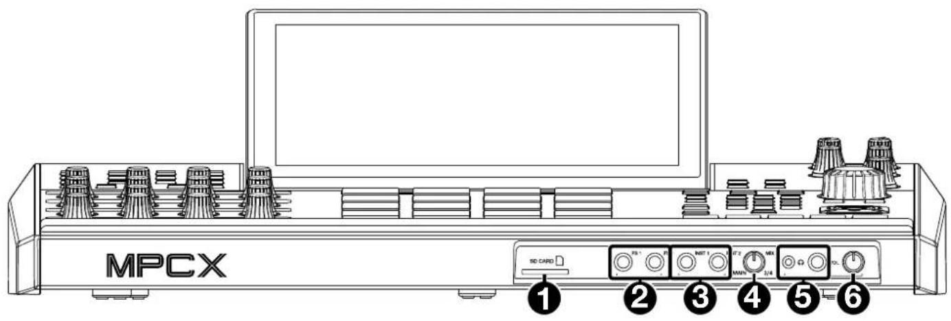
- SD Card Slot: Insert a standard SD/SDHC card into this slot to access its files directly using MPC X.
- Footswitch Inputs (FS 1/2) (1/4" / 6.35 mm): Connect optional 1/4" (6.35 mm) TS footswitches to these inputs.
- Instrument Inputs (Inst 1/2) (1/4" / 6.35 mm): Use standard 1/4" (6.35 mm) TS cables to connect these inputs to audio sources (guitars, bass, etc.). To use each of these inputs, set the corresponding Rear/Front switch (below the Gain 1/2 knob on the top panel) to Front.
- Mix Knob: Turn this knob to adjust the balance between the Main and 3/4 signals in your headphones. Main is the signal sent from the Main L/R outputs. 3/4 is the signal sent from the Outputs 3/4.
- Headphone Outputs (1/8" or 1/4" / 3.5 mm or 6.35 mm): Connect your headphones (not included) to either or both of these standard stereo outputs. Use the Mix Knob to determine what signal is heard in the headphones. Turn the Headphone Volume knob to set the volume level.
- Headphone Volume: Turn this knob to adjust the volume of the headphone outputs.
Rear Panel

- Power Input: Use the included power adapter to connect MPC X to a power outlet. This must be connected to a power outlet in order for MPC X to power on.
- Power Adapter Restraint: Secure the power adapter cable to this restraint to prevent it from accidentally unplugging.
- Power Switch: Press this button to turn MPC X's power on or off. While powered on, press and hold this button for 5 seconds to force MPC X to power off (similar to a computer).
- USB-B Port: Use the included USB cable to connect this USB 3.0 port to an available USB 3.0 port on your computer. This connection allows MPC X to send/receive MIDI and audio data to/from the MPC software on your computer. It also allows any connected USB drives, SD cards, and drives connected to the internal SATA port to mount on your computer if MPC X is in Controller Mode (i.e., your computer can access these storage devices that are connected to your MPC X).
- USB-A Ports: Connect USB flash drives to these USB ports to access their files directly using MPC X. MPC X supports read and write capability for exFAT, FAT32, NTFS, and EXT4 file systems as well as read-only capability for HFS+ file systems. (We recommend using an exFAT file system as it is the most robust one supported by both Windows and macOS.) These USB ports supply power to connected USB devices and can also be used to receive MIDI messages from external USB MIDI devices.
- Inputs 1/2 (XLR or 1/4" / 6.35 mm): Use standard XLR or 1/4" (6.35 mm) TRS cables to connect these inputs to audio sources (microphone, mixer, synthesizer, etc.). To use each of these inputs, set the corresponding Rear/Front switch (below the Gain 1/2 knob on the top panel) to Rear. Turn the Gain 1/2 knobs to set the input level of each one.
Note: When using the XLR connection, the mic pre-amp is automatically engaged. When using a 1/4" (6.35 mm) TRS cable, the mic pre-amp is bypassed. - Inputs 3/4 (1/4" / 6.35 mm or RCA): Use standard 1/4" (6.35 mm) TRS cables or stereo RCA cables to connect these inputs to audio sources (mixer, turntable, synthesizer, etc.). To use the 1/4" (6.35 mm) inputs, set the Phono/Line switch to Line. To use the RCA inputs, set the Phono/Line switch to Phono. Turn the 3/4 Rec Gain knob to set their input levels.
- Phono/Line Switch: Set this switch to the appropriate position, depending on which Input 3/4 connectors you want to use. If you are using the 1/4" (6.35 mm) inputs, set this switch to Line. If you are using the RCA inputs, set this switch to Phono to provide the additional amplification needed for phono-level signals.
- Grounding Terminal: If you are sending a phono-level turntable signal to the Input 3/4 RCA connectors and are hearing a low hum or buzz, it could mean that the turntable is not grounded. If the turntable has a grounding wire, connect it to this terminal.
Note: Some turntables have a grounding wire built into the RCA connection and, therefore, nothing needs to be connected to the grounding terminal. - Main L/R Outputs (1/4" / 6.35 mm): Use standard 1/4" (6.35 mm) TRS cables to connect these outputs to your speaker system. The signal sent out of these outputs is the main mix. Turn the Master knob to set their volume.
Tip: To route a track to these outputs, set its routing to Out 1,2 in the Channel Mixer when the Mixer field is set to Tracks. See Operation > Modes > Channel Mixer to learn more about this. - Outputs 3/4, 5/6, 7/8 (1/4" / 6.35 mm): Use standard 1/4" (6.35 mm) TRS cables to connect these outputs to an external mixer. The signal sent from these outputs is full-volume (0 dB).
Tip: To route a track to these outputs, set its routing to Out 1,2, Out 5,6, or Out 7,8 (respectively) in the Channel Mixer when the Mixer field is set to Tracks. See Operation > Modes > Channel Mixer to learn more about this. - MIDI In: Use standard 5-pin MIDI cables to connect these inputs to the MIDI outputs of optional external MIDI devices.
- MIDI Out: Use standard 5-pin MIDI cables to connect these outputs to the MIDI inputs of optional external MIDI devices.
- CV/Gate Out: Use standard 1/8" (3.5 mm) TS cables to connect these outputs to optional external sequencers. MPC X will send control voltage (CV) and/or Gate data over this connection.
MPC Live
Top Panel
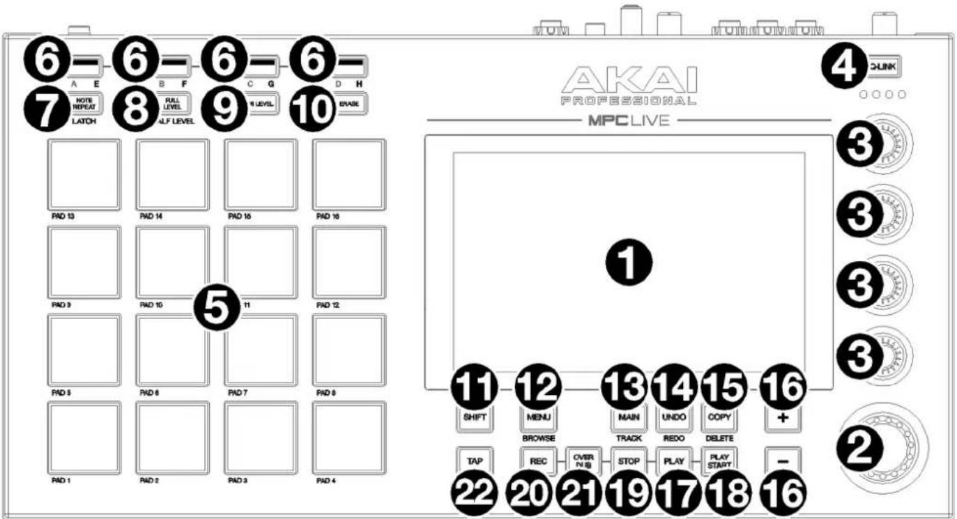
- Touchscreen: This full-color multi-touch display shows information relevant to MPC Live's current operation. Touch the touchscreen (and use the hardware controls) to control the MPC interface.
- Data Dial: Use this dial to scroll through the available menu options or adjust the parameter values of the selected field on the screen. Pressing the dial also functions as an Enter button.
- Q-Link Knobs: Use these touch-sensitive knobs to adjust various parameters and settings. The knobs can control one group of parameters at a time. The lights below the Q-Link button indicate the currently selected column of Q-Link knobs. Press the Q-Link button to change which parameter or group of parameters they currently control.
- Q-Link Button: Press this button to change which parameter or group of parameters the Q-Link knobs currently control (indicated by the lights above the Q-Link knobs). Each press will select the next column of Q-Link knobs.
Press and hold Shift and then press this button to select the previous column of Q-Link knobs instead.
Press and hold this button to show the QLink window over the touchscreen's current contents. These are the same parameters and settings as what is shown in Q-Link Edit Mode. You can tap Q-Link Edit at the bottom of the window to enter Q-Link Edit Mode immediately (see Operation > Modes > Q-Link Edit Mode to learn about this).
- Pads: Press these pads to trigger drum hits or other samples in your software. The pads are velocity-sensitive and pressure-sensitive, which makes them very responsive and intuitive to play. The pads will light up different colors, depending on how hard you play them (ranging from yellow at a low velocity to red at the highest velocity). You can also customize their colors.
- Pad Bank: Press any of these buttons to access Pad Banks A–D.
Press and hold Shift while pressing any of these buttons to access Pad Banks E-H. Alternatively, double-press one of these buttons.
- Note Repeat/Latch: Press and hold this button, and then press a pad to trigger that pad's sample repeatedly. The rate is based on the current tempo and Timing Correct settings.
Press and hold Shift and then press this button to "latch" the Note Repeat feature. When latched, you do not have to hold the Note Repeat button for it to be activated. Press Note Repeat once more to unlatch it.
- Full Level/Half Level: Press this button to activate or deactivate the Full Level feature. When activated, the pads will always trigger their samples at the maximum velocity (127), regardless of how much force you use.
Press and hold Shift and then press this button to activate or deactivate the Half Level feature. When activated, the pads will always trigger their samples at half-velocity (64).
Press and hold this button to set a custom user level velocity that can be used in place of Half Level.
- 16 Level / Pad Perform: Press this button to activate/deactivate 16 Level. When activated, the last pad that was hit will be temporarily copied to all 16 pads. The pads will now output the same note number as the initial pad, but a selectable parameter will be fixed at values that increase as the pad numbers increase (e.g., Pad 1 is the minimum, Pad 16 is the maximum), regardless of how hard you press them. In the screen that appears, use the Type selector to choose the parameter: Velocity, Tune, Filter, Layer, Attack or Decay. See Operation > General Features > 16 Level to learn more.
Press and hold Shift and press this button to enter Pad Perform mode for the pads. When activated, you can play musical scales/modes, chords or progressions using the pads while in any mode. See Operation > General Features > Pad Perform to learn more.
-
Erase: As a sequence is playing, press and hold this button and then press a pad to delete the note event for that pad at the current playback position. This is a quick way to delete note events from your sequence without having to stop playback. See Operation > General Features > Erase to learn more.
-
Shift: Press and hold this button to access some buttons' secondary functions (indicated by gray writing).
Double-press this button to see which buttons have secondary functions—the buttons will flash for a few seconds.
- Menu/Browse: Press this button to open the Menu. You can tap an option in the Menu to enter that mode, view, etc.
Press and hold Shift and then press this button to view the Browser. You can use the Browser to locate and select tracks, samples, sequences, etc.
- Main/Track: Press this button to enter Main Mode.
Press and hold Shift and then press this button to enter the Track View.
- Undo/Redo: Press this button to undo your last action.
Press and hold Shift and press this button to redo the last action you undid.
- Copy/Delete: Press this button to copy one pad to another. When the From Pad field is selected, press the "source" pad (the pad you want to copy). When the To Pad graphic (of all pads) is selected, press the "destination" pad. You can select multiple destination pads, and you can select pads in different pad banks. Tap Do It to continue or Close to return to the previous screen.
Tip: To quickly copy a pad, press and hold Copy, press the source pad, press the destination pad, and then release Copy.
Press and hold Shift and press this button to delete a pad's sample assignment. When the Delete Pad window is shown, press any pad/pads whose sample assignments you want to clear. Tap Delete to continue or Cancel to return to the previous screen.
-
-/+ : Press these buttons to increase or decrease the value of the selected field on the screen.
-
Play: Press this button to play the sequence from the audio pointer's current position.
-
Play Start: Press this button to play the sequence from its start point.
-
Stop: Press this button to stop playback. You can double-press this button to silence audio that is still sounding once a note stops playing. Quickly pressing this button three times will function as a "MIDI panic" and shut off all voices and stop all audio processing.
-
Rec: Press this button to record-arm the sequence. Press Play or Play Start to start recording. Recording in this way (as opposed to using Overdub) erases the events of the current sequence. After the sequence plays through once while recording, Overdub will be enabled.
-
Overdub: Press this button to enable Overdub. When enabled, you can record events in a sequence without overwriting any previously recorded events. You can enable Overdub before or during recording.
-
Tap/Master: Press this button in time with the desired tempo to enter a new tempo (in BPM). You can set how many taps are required in the Preferences (see Operation > General Features > Menu > Preferences to learn how to do this).
Press and hold Shift and press this button to set whether the currently selected sequence follows its own tempo (the button will be lit red) or a global tempo (the button will be lit amber).
Rear Panel

- Power Input: Use the included power adapter to connect MPC Live to a power outlet.
- Power Switch: Turns MPC Live's power on/off.
- Charging Indicator: This light (behind the vent) will turn on when MPC Live's internal battery is charging (when the power input is connected to a power outlet). When the battery is fully charged or when it is disconnected from a power outlet, then this light will turn off.
- USB-B Port: Use the included USB cable to connect this USB 3.0 port to an available USB 3.0 port on your computer. This connection allows MPC Live to send/receive MIDI and audio data to/from the MPC software on your computer. It also allows any connected USB drives, SD cards, and drives connected to the internal SATA port to mount on your computer if MPC Live is in Controller Mode (i.e., your computer can access these storage devices that are connected to your MPC Live).
- USB-A Ports: Connect USB flash drives to these USB ports to access their files directly using MPC Live. MPC Live supports read and write capability for exFAT, FAT32, NTFS, and EXT4 file systems as well as read-only capability for HFS+ file systems. (We recommend using an exFAT file system as it is the most robust one supported by both Windows and macOS.) These USB ports supply power to connected USB devices and can also be used to receive MIDI messages from external USB MIDI devices.
- SD Card Slot: Insert a standard SD/SDHC card into this slot to access its files directly using MPC Live.
- Rec Vol: Turn this knob to adjust the gain of the incoming signal from the 1/4" (6.35 mm) and RCA inputs. Be careful when setting this knob at higher levels, which can cause the signal to distort.
- Master Vol: Turn this knob to adjust the volume of Output 1/2 and the phones output.
- Inputs (1/4" / 6.35 mm): Use standard 1/4" (6.35 mm) TRS cables to connect these inputs to audio sources (microphone, mixer, synthesizer, etc.). To use these inputs, set the Line/Phono switch to Line. Turn the Rec Vol knob to set their input levels.
- Inputs (RCA): Use a standard RCA stereo cable to connect these inputs to a phono-level audio source like a turntable. To use these inputs, set the Line/Phono switch to Phono. Turn the Rec Vol knob to set their input levels.
- Line/Phono Switch: Set this switch to the appropriate position, depending on which inputs you want to use. If you are using the RCA inputs, set this switch to Phono to provide the additional amplification needed for phonolevel signals. If you are using the 1/4" (6.35 mm) inputs, such as a keyboard or a sampler, set this switch to Line.
- Grounding Terminal: If using phono-level turntables with a grounding wire, connect the grounding wire to these terminals. If you experience a low "hum" or "buzz," this could mean that your turntables are not grounded.
Note: Some turntables have a grounding wire built into the RCA connection and, therefore, nothing needs to be connected to the grounding terminal.
- Outputs (1/4" / 6.35 mm): Use standard 1/4" (6.35 mm) TRS cables to connect these outputs to your speaker system, external mixer, etc. The signal sent out of the Master L/R outputs is the main mix. Turn the Master Vol knob to set their volume. The signals sent from Outputs 3–6 are full-volume (0 dB).
Tip: To route a track to these outputs, set its routing to Out 1,2, Out 3,4, or Out 5,6 (respectively) in the Channel Mixer when the Mixer field is set to Tracks. See Operation > Modes > Channel Mixer to learn more about this.
- Phones (1/8" / 3.5 mm): Connect standard 1/8" (3.5 mm) stereo headphones to this output. Turn the Master Vol knob to set the volume level.
- MIDI In: Use standard 5-pin MIDI cables to connect these inputs to the MIDI outputs of optional external MIDI devices.
- MIDI Out: Use standard 5-pin MIDI cables to connect these outputs to the MIDI inputs of optional external MIDI devices.
- Kensington ^® Lock Slot: You can use this slot to secure your MPC Live to a table or other surface.
MPC Live II
Top Panel
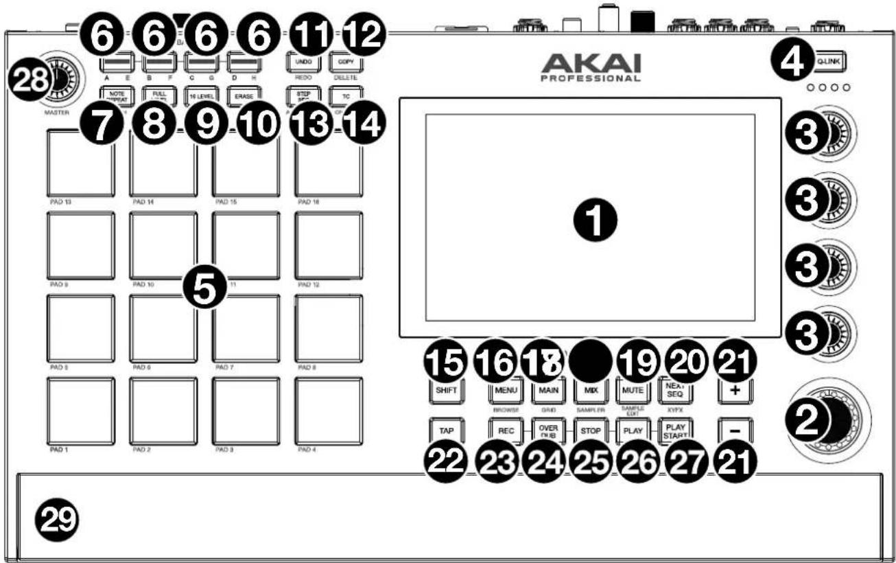
- Touchscreen: This full-color multi-touch display shows information relevant to MPC Live II's current operation. Touch the display (and use the hardware controls) to control the MPC interface.
- Data Dial: Use this dial to scroll through the available menu options or adjust the parameter values of the selected field in the display. Pressing the dial also functions as an Enter button.
- Q-Link Knobs: Use these touch-sensitive knobs to adjust various parameters and settings. The knobs can control one column of parameters at a time. The lights above the Q-Link Knobs indicate the currently selected column. Press the Q-Link button above them to change which column of parameters they currently control.
- Q-Link Button: Press this button to change which column of parameters the Q-Link Knobs currently control (indicated by the lights above the Q-Link Knobs). Each press will select the next column.
Press and hold Shift and then press this button to select the previous column instead.
Press and hold this button to show the QLink window over the touchscreen's current contents. These are the same parameters and settings as what is shown in Q-Link Edit Mode. You can tap Q-Link Edit at the bottom of the window to enter Q-Link Edit Mode immediately (see Operation > Modes > Q-Link Edit Mode to learn about this).
- Pads: Use these pads to trigger drum hits or other samples. The pads are velocity-sensitive and pressure-sensitive, which makes them very responsive and intuitive to play. The pads will light up different colors, depending on how hard you play them (ranging from yellow at a low velocity to red at the highest velocity). You can also customize their colors.
- Pad Bank Buttons: Press any of these buttons to access Pad Banks A-D. Press and hold Shift while pressing any of these buttons to access Pad Banks E-H. Alternatively, double-press one of these buttons.
- Note Repeat / Latch: Press and hold this button, and then press a pad to trigger that pad's sample repeatedly. The rate is based on the current tempo and Timing Correct settings.
Press and hold Shift and then press this button to "latch" the Note Repeat feature. When latched, you do not have to hold the Note Repeat button for it to be activated. Press Note Repeat once more to unlatch it.
- Full Level / Half Level: Press this button to activate/deactivate Full Level. When activated, the pads will always trigger their samples at the maximum velocity (127), regardless of the amount of force you use.
Press and hold Shift and then press this button to activate/deactivate Half Level. When activated, the pads will always trigger their samples at half-velocity (64).
Press and hold this button to set a custom user level velocity that can be used in place of Half Level.
- 16 Level / Pad Perform: Press this button to activate/deactivate 16 Level. When activated, the last pad that was hit will be temporarily copied to all 16 pads. The pads will now output the same note number as the initial pad, but a selectable parameter will be fixed at values that increase as the pad numbers increase (e.g., Pad 1 is the minimum, Pad 16 is the maximum), regardless of how hard you press them. In the screen that appears, use the Type selector to choose the parameter: Velocity, Tune, Filter, Layer, Attack or Decay. See Operation > General Features > 16 Level to learn more.
Press and hold Shift and press this button to activate/deactivate Pad Perform mode for the pads. When activated, you can play musical scales/modes, chords or progressions using the pads while in any mode. Use the Pad Perform window to configure the settings for the pads.
- Erase: As a Sequence is playing, press and hold this button and then press a pad to delete the note event for that pad at the current playback position. This is a quick way to delete note events from your sequence without having to stop playback. When playback is stopped, press this button to open the Erase window where notes, automation and other sequence data can be erased from the sequence. See Operation > General Features > Erase to learn more.
- Undo / Redo: Press this button to undo your last action. Hold down Shift and press this button to redo the last action you undid.
- Copy / Delete: Press this button to copy one pad to another. When the From Pad field is selected, press the "source" pad (the pad you want to copy). When the To Pad graphic (of all pads) is selected, press the "destination" pad. You can select multiple destination pads, and you can select pads in different pad banks. Tap Do It to continue or Cancel to return to the previous screen.
Press and hold Shift and press this button to delete.
- Step Seq/Automation: Press this button to view Step Sequencer mode where you can create or edit sequences by using the pads as "step buttons," simulating the experience of a traditional step-sequencer-style drum machine.
Press and hold Shift and press this button to toggle the Global Automation state between Read and Write.
- TC / On/Off: Press this button to open the Timing Correct (TC) window, which contains various settings to help quantize the events in your sequence.
Press and hold Shift and press this button to turn Timing Correct on and off.
- Shift: Press and hold this button to access some buttons' secondary functions (indicated by gray writing).
Double-press this button to see which buttons have secondary functions—the buttons will flash for a few seconds.
- Menu / Browse: Press this button to open the mode Menu. You can tap an option on the Menu screen to enter that mode, view, etc.
Press and hold Shift and then press this button to view the Browser. You can use the Browser to locate and select tracks, samples, sequences, etc.
- Main / Grid: Press this button to enter Main Mode.
Press and hold Shift and then press this button to enter Grid View mode.
- Mix / Sampler: Press this button to view the last used Mixer Mode, either Channel Mixer (default) or Pad Mixer. In Channel Mixer Mode, you can set levels, stereo panning, and other settings for your tracks, returns, submixes, and main outputs. In Pad Mixer Mode, you can set a track's levels, stereo panning, routing, and effects. Pressing the button multiple times will toggle between the two Mixer Modes.
Press and hold Shift and then press this button to view the Sampler, where you can record audio samples to use in your projects.
- Mute / Sample Edit: Press this button to view the last used Mute Mode, either Track Mute (default) or Pad Mute. In Track Mute Mode, you can mute tracks within a sequence or set mute groups for each track. In Pad Mute Mode, you can mute pads within a track or set mute groups for each pad within a track. Pressing the button multiple times will toggle between the two Mute Modes.
Press and hold Shift and then press this button to enter Sample Edit Mode where you can edit your samples using various functions and processes.
- Next Seq / XYFX: Press this button to view Next Sequence Mode where you can trigger different sequences simply by playing the pads. This is useful for live performances, letting you change a song's structure in real time.
Press and hold Shift and press this button to view XYFX Mode, which turns the touchscreen into an XY pad where each axis represents the range of an effect parameter. As you move touch or move your finger on the touchscreen, the current position will determine the current value of the two parameters. You can use this mode to create interesting effect automation on your tracks.
-
-/+ : Press these buttons to decrease/increase the value of the selected field in the display.
-
Tap Tempo / Master: Press this button in time with the desired tempo to enter a new tempo (in BPM). You can set how many taps are required in the Preferences (see Operation > General Features > Menu > Preferences to learn how to do this).
Press and hold Shift and press this button to set whether the currently selected sequence follows its own tempo (the button will be lit amber) or a global tempo (the button will be lit red). - Rec: Press this button to record-arm the sequence. Press Play or Play Start to start recording. Recording in this way (as opposed to using Overdub) erases the events of the current sequence. After the sequence plays through once while recording, Overdub will be enabled.
- Overdub: Press this button to enable Overdub. When enabled, you can record events in a Sequence without overwriting any previously recorded events. You can enable Overdub before or during recording.
- Stop: Press this button to stop playback. You can double-press this button to silence audio that is still sounding once a note stops playing. Press and hold Shift and press this button to stop playback and return the playhead to 1:1:0.
- Play: Press this button to play the sequence from the playhead's current position.
- Play Start: Press this button to play the sequence from its start point.
- Master Vol: Turn this knob to adjust the volume of the Master L/R outputs, phones output and speakers.
- Speakers: When the Speaker switch on the rear panel is set to On, these speakers will play the current audio. Use the Master Volume knob to control the volume of the speakers.
Rear Panel

- Power Input: Use the included power adapter to connect MPC Live II to a power outlet.
- Power Adapter Restraint: Secure the power adapter cable to this restraint to prevent it from accidentally unplugging.
- Power Switch: Turns MPC Live II's power on/off.
- Charging Indicator: This light (behind the vent) will turn on when MPC Live II's internal battery is charging (when the power input is connected to a power outlet). When the battery is fully charged or when it is disconnected from a power outlet, then this light will turn off.
- Link: Connect a standard Ethernet cable to this port to use Ableton Link and other compatible devices with MPC Live II. See Operation > General Features > Menu > Sync for more information.
Note: You can also use Ableton Link wirelessly over a Wi-Fi connection. - USB-B Port: Use the included USB cable to connect this high-retention-force USB port to an available USB port on your computer. This connection allows MPC Live II to send/receive MIDI and audio data to/from the MPC software on your computer.
- USB-A Ports: Connect USB flash drives to these USB ports to access their files directly using MPC Live II. When connected to a computer in Controller Mode, you can access drives connected to this port from your computer. You can also connect standard MIDI controllers to these ports.
- SD Card Slot: Insert a standard SD, SDHC or SDXC card into this slot to access its files directly using MPC Live II.
- Rec Vol: Turn this knob to adjust the volume of the inputs.
- Inputs (1/4" / 6.35 mm): Use standard 1/4" (6.35 mm) TRS cables to connect these inputs to an audio source (mixer, synthesizer, drum machine, etc.). In Sample Record Mode, you can select whether you want to record either channel or both channels in stereo or in mono. To use these inputs, set the Line/Phono switch to Line.
- Inputs (RCA): Use a standard RCA stereo cable to connect these inputs to a phono-level audio source like a turntable. In Sample Record Mode, you can select whether you want to record either channel or both channels in stereo or in mono. To use these inputs, set the Line/Phono switch to Phono.
- Line/Phono Switch: Set this switch to the appropriate position, depending on which inputs you want to use. If you are using the RCA inputs, set this switch to Phono to provide the additional amplification needed for phonolevel signals. If you are using the 1/4" (6.35 mm) inputs, such as a CD player or sampler, set this switch to Line.
- Grounding Terminal: If using phono-level turntables with a grounding wire, connect the grounding wire to these terminals. If you experience a low "hum" or "buzz," this could mean that your turntables are not grounded.
Note: Some turntables have a grounding wire built into the RCA connection and, therefore, nothing needs to be connected to the grounding terminal. - Outputs (1/4" / 6.35 mm): Use standard 1/4" (6.35 mm) TRS cables to connect these outputs to your monitors, mixer, etc.). The Master L/R outputs are the same as Outputs 1,2.
- Phones (1/4" / 6.35 mm): Connect standard 1/4" (6.35 mm) stereo headphones to this output.
- Speaker On/Off: Use this switch to turn the MPC Live II internal speakers on or off.
- MIDI In: Use a standard 5-pin MIDI cable to connect these inputs to the MIDI output of an external MIDI device (synthesizer, drum machine, etc.).
- MIDI Out: Use a standard 5-pin MIDI cable to connect these outputs to the MIDI input of an external MIDI device (synthesizer, drum machine, etc.).
- CV/Gate Out: MPC Live II will send control voltage (CV) and/or Gate signals over these outputs to optional external sequencers. Use standard 1/8" (3.5 mm) TS cables to send a single CV/Gate signal per output, or use a stereo TRS-to-dual mono TSF breakout cable (such as a Hosa YMM-261) to send two CV/Gate signals per output.
- Kensington® Lock Slot: You can use this slot to secure your MPC Live II to a table or other surface.
MPC One / MPC One+
Note: Mentions of the features and functions of MPC One hardware throughout this guide also apply to the MPC One+ unless otherwise noted.
Top Panel

Navigation & Data Entry Controls
- Touchscreen: This full-color multi-touch display shows information relevant to MPC One's current operation. Touch the display (and use the hardware controls) to control the MPC interface.
- Data Dial: Use this dial to scroll through the available menu options or adjust the parameter values of the selected field in the display. Pressing the dial also functions as an Enter button.
- -/+ : Press these buttons to increase or decrease the value of the selected field in the display.
- Undo / Redo: Press this button to undo your last action. Press and hold Shift and press this button to redo the last action you undid.
- Shift: Press and hold this button to access some buttons' secondary functions (indicated by red writing).
Pad & Q-Link Controls
- Pads: Use these pads to trigger drum hits or other samples. The pads are velocity-sensitive and pressure-sensitive, which makes them very responsive and intuitive to play. The pads will light up different colors, depending on how hard you play them (ranging from yellow at a low velocity to red at the highest velocity). You can also customize their colors.
- Pad Bank Buttons: Press any of these buttons to access Pad Banks A–D. Press and hold Shift while pressing any of these buttons to access Pad Banks E–H. Alternatively, double-press one of these buttons.
- Full Level / Half Level: Press this button to activate/deactivate Full Level. When activated, the pads will always trigger their samples at the maximum velocity (127), regardless of the amount of force you use.
Press and hold Shift and then press this button to activate/deactivate Half Level. When activated, the pads will always trigger their samples at half-velocity (64).
Press and hold this button to set a custom user level velocity that can be used in place of Half Level. - 16 Level / Pad Perform (Notes): Press this button to activate/deactivate 16 Level. When activated, the last pad that was hit will be temporarily copied to all 16 pads. The pads will now output the same note number as the initial pad, but a selectable parameter will be fixed at values that increase as the pad numbers increase (e.g., Pad 1 is the minimum, Pad 16 is the maximum), regardless of how hard you press them. In the screen that appears, use the Type selector to choose the parameter: Velocity, Tune, Filter, Layer, Attack or Decay. See Operation > General Features > 16 Level to learn more.
Press and hold Shift and press this button to enter Pad Perform (Notes) mode for the pads. When activated, you can play musical scales/modes, chords or progressions using the pads while in any mode. See Operation > General Features > Pad Perform o learn more. - Copy / Delete: Press this button to copy one pad to another. When the From Pad field is selected, press the "source" pad (the pad you want to copy). When the To Pad graphic (of all pads) is selected, press the "destination" pad. You can select multiple destination pads, and you can select pads in different pad banks. Tap Do It to continue or Cancel to return to the previous screen.
Press and hold Shift and press this button to delete. - Note Repeat / Latch: Press and hold this button, and then press a pad to trigger that pad's sample repeatedly. The rate is based on the current tempo and Timing Correct settings.
Press and hold Shift and then press this button to "latch" the Note Repeat feature. When latched, you do not have to hold the Note Repeat button for it to be activated. Press Note Repeat once more to unlatch it. - Q-Link Knobs: Use these touch-sensitive knobs to adjust various parameters and settings. The knobs can control one column of parameters at a time. The lights above the Q-Link Knobs indicate the currently selected column. Press the Q-Link button to change which column of parameters they currently control.
- Q-Link Button: Press this button to change which column of parameters the Q-Link Knobs currently control (indicated by the lights above the Q-Link Knobs). Each press will select the next column.
Press and hold Shift and then press this button to select the previous column instead.
Mode & View Controls
- Menu / Prefs: Press this button to open the mode Menu. You can tap an option on the Menu screen to enter that mode, view, etc.
Press and hold Shift and then press this button to open the Preferences page in the Menu.
- Main / Grid: Press this button to enter Main Mode.
Press and hold Shift and then press this button to enter Grid View mode.
- Browse / Save: Press this button to view the Browser. You can use the Browser to locate and select tracks, samples, sequences, etc.
Press and hold Shift and then press this button to save the current project (including its samples, tracks, sequences, and songs).
- Track Mix / Pad Mix: Press this button to view the Channel Mixer where you can set levels, stereo panning, and other settings for your tracks, returns, submixes, and main outputs.
Press and hold Shift and then press this button to view the Pad Mixer where you can set a track's levels, stereo panning, routing, and effects.
- Track Mute / Pad Mute: Press this button to view Track Mute Mode where you can easily mute tracks within a sequence or set mute groups for each track.
Press and hold Shift and press this button to view Pad Mute Mode where you can easily mute pads within a track or set mute groups for each pad within a track.
- Next Seq / XYFX: Press this button to view Next Sequence Mode where you can trigger different sequences simply by playing the pads. This is useful for live performances, letting you change a song's structure in real time.
Press and hold Shift and press this button to view XYFX Mode, which turns the touchscreen into an XY pad where each axis represents the range of an effect parameter. As you move touch or move your finger on the touchscreen, the current position will determine the current value of the two parameters. You can use this mode to create interesting effect automation on your tracks.
- Step Seq / Automation: Press this button to view Step Sequencer mode where you can create or edit sequences by using the pads as "step buttons," simulating the experience of a traditional step-sequencer-style drum machine.
Press and hold Shift and press this button to toggle Global Automation between Read and Write.
- TC / On/Off: Press this button to open the Timing Correct (TC) window, which contains various settings to help quantize the events in your sequence.
Press and hold Shift and press this button to turn Timing Correct on and off.
- Sampler / Looper: Press this button to view the Sampler where you can record audio samples to use in your projects.
Press and hold Shift and press this button to view the Looper where you can record and overdub audio in real time—a great tool for live performance as well as spontaneous moments in the studio. You can export the loop as a sample to use in your project.
- Sample Edit / Q-Link Edit: Press this button to view Sample Edit Mode where you can edit your samples using various functions and processes.
Press and hold Shift and press this button to view Q-Link Edit Mode where you can assign other parameters to the Q-Link knobs.
- Program Edit / MIDI Control: Press this button to view Track Edit Mode, which contains all parameters for editing your tracks.
Press and hold Shift and press this button to view MIDI Control Mode where you can customize what MIDI messages are sent from certain controls on your hardware.
Transport & Recording Controls
-
Rec: Press this button to record-arm the sequence. Press Play or Play Start to start recording. Recording in this way (as opposed to using Overdub) erases the events of the current sequence. After the sequence plays through once while recording, Overdub will be enabled.
-
Overdub: Press this button to enable Overdub. When enabled, you can record events in a Sequence without overwriting any previously recorded events. You can enable Overdub before or during recording.
-
Stop: Press this button to stop playback. You can double-press this button to silence audio that is still sounding once a note stops playing. Press and hold Shift and press this button to return the playhead to 1:1:0.
-
Play: Press this button to play the sequence from the playhead's current position.
-
Play Start: Press this button to play the sequence from its start point.
-
Tap Tempo / Master (Global): Press this button in time with the desired tempo to enter a new tempo (in BPM).
Press and hold Shift and press this button to set whether the currently selected sequence follows its own tempo (the button will be lit amber) or a global tempo (the button will be lit red).
- Erase: As a Sequence is playing, press and hold this button and then press a pad to delete the note event for that pad at the current playback position. This is a quick way to delete note events from your sequence without having to stop playback. When playback is stopped, press this button to open the Erase window where notes, automation and other sequence data can be erased from the sequence.
Front Panel

- SD Card Slot: Insert a standard SD, SDHC or SDXC card into this slot to access its files directly using MPC One.
- Phones (1/8" / 3.5 mm): Connect standard 1/8" (3.5 mm) stereo headphones to this output.
Rear Panel

- Power Input: Use the included power adapter to connect MPC One to a power outlet.
- Power Adapter Restraint: Secure the power adapter cable to this restraint to prevent it from accidentally unplugging.
- Power Switch: Turns MPC One's power on/off.
- Link: Connect a standard Ethernet cable to this port to use Ableton Link and other compatible devices with MPC One. See Operation > General Features > Menu > Sync for more information.
Note: You can also use Ableton Link wirelessly over a Wi-Fi connection.
Note: Not available on MPC One+.
- USB-B Port: Use the included USB cable to connect this high-retention-MPC One USB port to an available USB port on your computer. This connection allows MPC One to send/receive MIDI and audio data to/from the MPC software on your computer.
- USB-A Port: Connect a USB flash drive to this USB port to access files directly using MPC One. You can also connect a standard MIDI controller to this port.
- Rec Vol: Turn this knob to adjust the volume of the inputs.
- Inputs (1/4" / 6.35 mm): Use standard 1/4" (6.35 mm) TRS cables to connect these inputs to an audio source (mixer, synthesizer, drum machine, etc.). In Sample Record Mode, you can select whether you want to record either channel or both channels in stereo or in mono.
- Master Vol: Turn this knob to adjust the volume of the outputs and phones output.
- Outputs (1/4" / 6.35 mm): Use standard 1/4" (6.35 mm) TRS cables to connect these outputs to your monitors, mixer, etc.
- MIDI In: Use a standard 5-pin MIDI cable to connect this input to the MIDI output of an external MIDI device (synthesizer, drum machine, etc.).
- MIDI Out: Use a standard 5-pin MIDI cable to connect this output to the MIDI input of an external MIDI device (synthesizer, drum machine, etc.).
- CV/Gate Outs: MPC One will send control voltage (CV) and/or Gate signals over these outputs to optional external sequencers. Use standard 1/8" (3.5 mm) TS cables to send a single CV/Gate signal per output, or use a stereo TRS-to-dual mono TSF breakout cable (such as a Hosa YMM-261) to send two CV/Gate signals per output.
- Kensington ^® Lock Slot: You can use this slot to secure your MPC One to a table or other surface.
MPC Key 61
Top Panel

- Display: This full-color multi-touch display shows information relevant to MPC Key 61's current operation. Touch the display (and use the hardware controls) to control the MPC interface.
- Data Dial: Use this dial to scroll through the available menu options or adjust the parameter values of the selected field on the display. Pressing the dial also functions as an Enter button.
- -/+ : Press these buttons to increase or decrease the value of the selected field on the display.
- Q-Link Knobs: Use these touch-sensitive knobs to adjust various parameters and settings. The knobs can control one column of parameters at a time. The lights above the Q-Link button indicate the currently selected column. Press the Q-Link button to change which column of parameters they currently control.
- Q-Link Button: Press this button to change which column of parameters the Q-Link Knobs currently control (indicated by the lights above the button). Each press will select the next column.
Press and hold Shift and then press this button to view the Q-Link Configuration window. Press and hold Shift and then press this button again to return to the Main page. - </> (Event |</>): Use these buttons to move the audio pointer left/right, one step at a time.
Press and hold Locate and press one of these buttons to move the audio pointer to the previous/next event in the sequence grid. - Locate: Press this button to open the Locate window, which allows you to quickly jump to specific points in your project.
Press and hold this button to activate the secondary functions of the </> and <</> buttons (i.e., Event |</>| and Start/End, respectively). - <</>> (Start/End): Use these buttons to move the audio pointer left/right, one bar at a time.
Press and hold Locate and press one of these buttons to move the audio pointer to the start or end of the sequence grid. - Rec / Recall: Press this button to record-arm the sequence. Press Play or Play Start to start recording. Recording in this way (rather than using Overdub) erases the events of the current sequence. After the sequence plays through once while recording, Overdub will be enabled.
Press and hold Shift and press this button to recall recently played MIDI note events when recording was disabled and insert them into the current sequence. - Overdub: Press this button to enable Overdub, which allows you to record note events in a sequence without overwriting any previously recorded note events. You can enable Overdub either before or during recording.
- Stop / Return: Press this button to stop playback. Double-press this button to immediately stop all sound.
Press and hold Shift and press this button to stop playback and return the playhead to the Loop Start value. - Play: Press this button to play the sequence from the audio pointer's current position.
- Play Start: Press this button to play the sequence from its start point.
-
Edit / XYFX: Press this button to view Track Edit Mode, which contains all parameters for editing your tracks.
Press and hold Shift and press this button to view XYFX Mode, which turns the touchscreen into an XY pad where each axis represents the range of an effect parameter. As you touch or move your finger on the touchscreen, the current position will determine the current value of the two parameters. You can use this mode to create interesting effect automation on your tracks. -
Grid / Step Seq: Press this button to enter Grid View mode, where you can view and edit the note events of each track of a sequence in a project and their velocities.
Press and hold Shift and press this button to view Step Sequencer mode where you can create or edit sequences by using the pads as "step buttons," simulating the experience of a traditional step-sequencer-style drum machine.
- Mix / Pad: Press this button to view the Channel Mixer where you can set levels, stereo panning, and other settings for your tracks, returns, submixes, and main outputs.
Press and hold Shift and then press this button to view the Pad Mixer where you can set a track's levels, stereo panning, routing, and effects.
- Mute / Pad: Press this button to view Track Mute Mode where you can easily mute tracks within a sequence or set mute groups for each track.
Press and hold Shift and press this button to view Pad Mute Mode where you can easily mute pads within a track or set mute groups for each pad within a track.
- Automation Read/Write / Off: Press this button to toggle the Global Automation state between Read and Write.
Press and hold Shift and press this button to disable or enable Global Automation.
- Keyboard Control / MIDI CTRL: Press this button to view the Keyboard Control menu, where you can customize the functions of the keyboard and wheels, including velocity response, routing, MIDI assignments, ranges and more.
Press and hold Shift and press this button to view MIDI Control Mode, where you can use the device as a MIDI controller and customize what MIDI messages are sent from the hardware controls.
- Sample Edit / Sampler: Press this button to view Sample Edit Mode where you can edit your samples using various functions and processes.
Press and hold Shift and press this button to view the Sampler where you can record audio samples to use in your projects.
- Timing Correct / On/Off: Press this button to open the Timing Correct (TC) window, which contains various settings to help quantize the events in your sequence.
Press and hold Shift and press this button to turn Timing Correct on and off.
- Undo / Redo: Press this button to undo your last action.
Press and hold Shift and press this button to redo the last action you undid.
- Shift: Press and hold this button to access some buttons' secondary functions (indicated by white writing).

- Menu / Browse: Press this button to open the mode Menu. You can tap an option on the Menu screen to enter that mode, view, etc.
Press and hold Shift and then press this button to view the Browser. You can use the Browser to locate and select tracks, samples, sequences, etc.
- Main / Track: Press this button to view Main Mode.
Press and hold Shift and press this button to view Track View Mode, an overview of the tracks of each sequence. You can also set key ranges in this mode.
- Sounds / Favorites: Press this button to view Sounds Mode, where you can browse MPC Key 61's built-in instruments and presets.
Press and hold Shift and press this button to view Favorites, where you can quickly select instruments and presets that you have defined as your favorites.
-
Pads: Use these pads to trigger drum hits or other samples. The pads are velocity-sensitive and pressure-sensitive, which makes them very responsive and intuitive to play. The pads will light up different colors, depending on the current function. You can also customize their colors.
-
Pad Bank Buttons: Press any of these buttons to access Pad Banks A-D. Press and hold Shift while pressing any of these buttons to access Pad Banks E-H. Alternatively, double-press one of these buttons.
-
Full Level / Half Level: Press this button to activate/deactivate Full Level. When activated, the pads will always trigger their samples at the maximum velocity (127), regardless of the amount of force you use.
Press and hold Shift and press this button to activate/deactivate Half Level. When activated, the pads will always trigger their samples at half-velocity (64).
Press and hold this button to set a custom user level velocity that can be used in place of Half Level.
- 16 Level / Notes: Press this button to activate/deactivate 16 Level. When activated, the last pad that was hit will be temporarily copied to all 16 pads. The pads will play the same sample as the original pad, but a selectable parameter will increase in value with each pad number, regardless of the amount of force you use. In the screen that appears, use the Type selector to choose another parameter: Velocity, Tune, Filter, Layer, Attack or Decay. See Operation > General Features > 16 Level to learn more.
Press and hold Shift and press this button to activate/deactivate Notes mode for the pads. When activated, you can play musical scales/modes, chords or progressions using the pads while in any mode. Use the Pad Perform window to configure the settings for the pads. See Operation > General Features > Pad Perform to learn more.
-
Erase: As a Sequence is playing, press and hold this button and then press a pad or key to delete the note event for that pad or key at the current playback position. This is a quick way to delete note events from your sequence without having to stop playback. When playback is stopped, press this button to open the Erase window where notes, automation and other sequence data can be erased from the sequence.
-
Copy / Delete: Press this button to copy one pad to another in Drum tracks. When the From Pad field is selected, press the "source" pad (the pad you want to copy). When the To Pad graphic (of all pads) is selected, press the "destination" pad. You can select multiple destination pads, and you can select pads in different pad banks. Tap Do It to continue or Cancel to return to the previous screen.
Press and hold Shift and press this button to delete.
-
Touch Strip: The touch strip can be used as an expressive control for playing and can be configured to control Note Repeat, Pitch Bend, Modulation and more.
-
Touch Strip / Config: Press this button to cycle between control modes for the Touch Strip. Press and hold the button to quickly select one of the control modes.
Press and hold Shift and press this button to view the Touch Strip Configuration window.
- Touch FX / Config: Press this button to enable Touch FX control for the Touch Strip. This allows you to control parameters from the Touch FX plugin using the Touch Strip. Press and hold this button to quickly select a Touch FX preset.
Press and hold Shift and press this button to view the Touch FX Configuration window.
- Note Repeat / Latch: Press and hold this button, and then press a pad to trigger that pad's sample repeatedly. The rate is based on the current tempo and Timing Correct settings.
Press and hold Shift and press this button to "latch" the Note Repeat feature. When latched, you do not have to hold the Note Repeat button for it to be activated. Press Note Repeat once more to unlatch it.
- Tap Tempo / Global: Press this button in time with the desired tempo to enter a new tempo (in BPM). Press and hold this button to adjust the tempo manually using the data dial.
Press and hold Shift and press this button to set whether the currently selected sequence follows its own tempo (the button will be lit white) or a global tempo (the button will be lit red).
- Metronome / Config: Press this button to enable or disable the Metronome (Click/Metro).
Press and hold Shift and press this button, or press and hold this button, to open the Metronome Configuration window.
- Arp / Config: Press this button to enable or disable the internal Arpeggiator, whose rate is based on the current Tempo and Time Division settings.
Press and hold Shift and press this button, or press and hold this button, to configure the Arpeggiator's settings.
-
Latch: Press this button to enable or disable latch for the Arpeggiator. When latched, you do not have to hold the keys for the arpeggiation to continue.
-
Oct - / Oct +: Press these buttons to transpose the keyboard down or up one octave at a time. The lights below this button will indicate the current octave setting.
Press and hold Shift and press these buttons to transpose the keyboard down or up one semitone at a time.
Press and hold both buttons and press a key on the keyed to set the transposition to that value.
Press and hold both buttons and release to reset the transposition.
-
Keybed: Use this 61-key semi-weighted, velocity-sensitive keybed to input notes and aftertouch.
-
Pitch Wheel: The pitch bend wheel is primarily used to bend the notes played on the keyboard up or down. This allows you to play phrases not normally associated with keyboard playing, such as guitar-style riffs.
-
Modulation Wheel: The modulation wheel is typically used to add variation for the sound you are playing. This type of real-time controller was originally introduced on electronic keyboard instruments to give the performer options such as adding vibrato, just like the players of acoustic instruments do.
-
Main Volume: Turn this knob to adjust the volume of the outputs and phones output.
Rear Panel

- Power Input: Use the included power adapter to connect MPC Key 61 to a power outlet.
- Power Switch: Turns MPC Key 61's power on and off.
- Network: Connect a standard Ethernet cable to this port to use Ableton Link and other compatible devices with MPC Key 61. See Operation > General Features > Menu > Sync for more information.
Note: You can also use Ableton Link wirelessly over a Wi-Fi connection.
- USB-B Port: Use the included USB cable to connect this high-retention-force USB port to an available USB port on your computer. This connection allows MPC Key 61 to send/receive MIDI and audio data to/from the MPC software on your computer.
- USB-A Ports: Connect a USB flash drive to these USB ports to access its files directly using MPC Key 61. You can also connect any class-compliant MIDI device to these ports.
- Phones (1/4" / 6.35 mm): Connect standard stereo headphones to this output.
- Outputs (1/4" / 6.35 mm): Use standard TRS cables to connect these outputs to your monitors, mixer, etc.). The Main L/R outputs are the same as Outputs 1,2.
- Gain: Use these knobs to adjust the gain of the incoming signal from Input 1/2 on the rear panel. Be careful when setting this knob at higher levels, as this can cause the signal to distort.
- Inputs 1/2 (XLR or 1/4" / 6.35 mm): Use standard XLR or TRS cables to connect these inputs to audio sources (microphone, mixer, synthesizer, etc.). When using a 1/4" cable, the Mic preamp is removed from the circuit, and the Line/Inst switch can be used to set the impedance.
Turn the Gain knobs to set the input level of each one.
- Line/Inst: Use these switches to set Inputs 1/2 to accept either a Line-level or Instrument-level sound source when using a 1/4" connection.
- Phantom Power (+48V): This switch activates and deactivates phantom power for Inputs 1/2 when using an XLR connection. When activated, +48V of phantom power will be supplied to both inputs. Note that most dynamic microphones do not require phantom power, while most condenser microphones do. Refer to your microphone's documentation to check if it needs phantom power.

- CV/Gate Out (1/8" / 3.5 mm, TS): MPC Key 61 will send control voltage (CV) and/or Gate signals over these outputs to optional external synths or sequencers. Use standard 1/8" (3.5 mm) TS cables to send a single CV/Gate signal per output.
- MIDI In: Use a standard 5-pin MIDI cable to connect these inputs to the MIDI output of an external MIDI device (additional MIDI keyboard, pad controller, etc.).
- MIDI Out: Use a standard 5-pin MIDI cable to connect these outputs to the MIDI input of an external MIDI device (synthesizer, drum machine, etc.).
- MIDI Thru: Use a standard 5-pin MIDI cable to connect this thru-port to the MIDI input of an external MIDI device (synthesizer, drum machine, etc.). MIDI from the MIDI In will be sent through this output.
- Sustain (1/4" / 6.35 mm, TRS): This input accepts an optional momentary-contact foot pedal. When pressed, the pedal will sustain the sound you are playing without having to keep your fingers pressed down on the keys.
- FS2 (1/4" / 6.35 mm, TRS): Connect an optional 1/4" (6.35 mm) TRS footswitch or other foot pedal to this input.
- Expression (1/4" / 6.35 mm, TRS): Connect an optional expression pedal to this input for adding expressive changes during performances.
MPC Key 37
Top Panel

- Display: This full-color multi-touch display shows information relevant to MPC Key 37's current operation. Touch the display (and use the hardware controls) to control the MPC interface.
- Data Dial: Use this dial to scroll through the available menu options or adjust the parameter values of the selected field on the display. Pressing the dial also functions as an Enter button.
- -/+ : Press these buttons to increase or decrease the value of the selected field on the display.
- Q-Link Knobs: Use these touch-sensitive knobs to adjust various parameters and settings. The knobs can control one column of parameters at a time. The lights above the Q-Link button indicate the currently selected column. Press the Q-Link button to change which column of parameters they currently control.
- Q-Link Button: Press this button to change which column of parameters the Q-Link Knobs currently control (indicated by the lights above the button). Each press will select the next column.
Press and hold Shift and then press this button to view the Q-Link Configuration window. Press and hold Shift and then press this button again to return to the Main page. - Rec: Press this button to record-arm the sequence. Press Play or Play Start to start recording. Recording in this way (rather than using Overdub) erases the events of the current sequence. After the sequence plays through once while recording, Overdub will be enabled.
Press and hold Shift and press this button to recall recently played MIDI note events when recording was disabled and insert them into the current sequence. - Overdub: Press this button to enable Overdub, which allows you to record note events in a sequence without overwriting any previously recorded note events. You can enable Overdub either before or during recording.
- Stop: Press this button to stop playback. Double-press this button to immediately stop all sound.
Press and hold Shift and press this button to stop playback and return the playhead to the Loop Start value. - Play: Press this button to play the sequence from the playhead's current position.
- Play Start: Press this button to play the sequence from its start point.
- Sounds / Favorites: Press this button to view Sounds Mode, where you can browse MPC Key 37's built-in instruments and presets.
Press and hold Shift and press this button to view Favorites, where you can quickly select instruments and presets that you have defined as your favorites. - Menu / Prefs: Press this button to open the mode Menu. You can tap an option on the Menu screen to enter that mode, view, etc.
Press and hold Shift and then press this button to open the Preferences page in the Menu. -
Main / Track: Press this button to view Main Mode.
Press and hold Shift and press this button to view Track View Mode, an overview of the tracks of each sequence. You can also set key ranges in this mode. -
Edit / XYFX: Press this button to view Track Edit Mode, which contains all parameters for editing your tracks.
Press and hold Shift and press this button to view XYFX Mode, which turns the touchscreen into an XY pad where each axis represents the range of an effect parameter. As you touch or move your finger on the touchscreen, the current position will determine the current value of the two parameters. You can use this mode to create interesting effect automation on your tracks.
- Grid / Step Seq: Press this button to enter Grid View mode, where you can view and edit the note events of each track of a sequence in a project and their velocities.
Press and hold Shift and press this button to view Step Sequencer mode where you can create or edit sequences by using the pads as "step buttons," simulating the experience of a traditional step-sequencer-style drum machine.
- Mix / Pad: Press this button to view the Channel Mixer where you can set levels, stereo panning, and other settings for your tracks, returns, submixes, and main outputs.
Press and hold Shift and then press this button to view the Pad Mixer where you can set a track's levels, stereo panning, routing, and effects.
- Undo / Redo: Press this button to undo your last action.
Press and hold Shift and press this button to redo the last action you undid.
- Automation / On/Off: Press this button to toggle the Global Automation state between Read and Write.
Press and hold Shift and press this button to disable or enable Global Automation.
- TC / On/Off: Press this button to open the Timing Correct (TC) window, which contains various settings to help quantize the events in your sequence.
Press and hold Shift and press this button to turn Timing Correct on and off.
- Load / Looper: Press this button to view the Browser. You can use the Browser to locate and select tracks, samples, sequences, etc.
Press and hold Shift and press this button to view the Looper where you can record and overdub audio in real time—a great tool for live performance as well as spontaneous moments in the studio. You can export the loop as a sample to use in your project.
- Save / Save As: Press this button to save the current project.
Press and hold Shift and press this button to open the Save window.
- Sample Edit / Sampler: Press this button to view Sample Edit Mode where you can edit your samples using various functions and processes.
Press and hold Shift and press this button to view the Sampler where you can record audio samples to use in your projects.
-
Shift: Press and hold this button to access some buttons' secondary functions (indicated by white writing).
-
Arp / Config: Press this button to enable or disable the internal Arpeggiator, whose rate is based on the current Tempo and Time Division settings.
Press and hold Shift and press this button, or press and hold this button, to configure the Arpeggiator's settings.
- Latch / Chord: Press this button to enable or disable latch for the Arpeggiator. When latched, you do not have to hold the keys for the arpeggiation to continue.
Play a chord on the keyboard and then press and hold Shift and press this button to enable Chord Mode. Playing any note will now play the full chord transposed to the new note with a single key press.
- Metronome / Config: Press this button to enable or disable the Metronome (Click/Metro).
Press and hold Shift and press this button, or press and hold this button, to open the Metronome Configuration window.
- Keyboard Control / MIDI CTRL: Press this button to view the Keyboard Control menu, where you can customize the functions of the keyboard and wheels, including velocity response, routing, MIDI assignments, ranges and more.
Press and hold Shift and press this button to view MIDI Control Mode, where you can use the device as a MIDI controller and customize what MIDI messages are sent from the hardware controls.
- Tap Tempo / Global: Press this button in time with the desired tempo to enter a new tempo (in BPM). Press and hold this button to adjust the tempo manually using the data dial.
Press and hold Shift and press this button to set whether the currently selected sequence follows its own tempo (the button will be lit white) or a global tempo (the button will be lit red).

- Mute / Pad: Press this button to view Track Mute Mode where you can easily mute tracks within a sequence or set mute groups for each track.
Press and hold Shift and press this button to view Pad Mute Mode where you can easily mute pads within a track or set mute groups for each pad within a track. - Pads: Use these pads to trigger drum hits or other samples. The pads are velocity-sensitive and pressure-sensitive, which makes them very responsive and intuitive to play. The pads will light up different colors, depending on the current function. You can also customize their colors.
- Pad Bank Buttons: Press any of these buttons to access Pad Banks A-D. Press and hold Shift while pressing any of these buttons to access Pad Banks E-H. Alternatively, double-press one of these buttons.
- Full Level / Half Level: Press this button to activate/deactivate Full Level. When activated, the pads will always trigger their samples at the maximum velocity (127), regardless of the amount of force you use.
Press and hold Shift and press this button to activate/deactivate Half Level. When activated, the pads will always trigger their samples at half-velocity (64).
Press and hold this button to set a custom user level velocity that can be used in place of Half Level.
- 16 Level / Notes: Press this button to activate/deactivate 16 Level. When activated, the last pad that was hit will be temporarily copied to all 16 pads. The pads will play the same sample as the original pad, but a selectable parameter will increase in value with each pad number, regardless of the amount of force you use. In the screen that appears, use the Type selector to choose another parameter: Velocity, Tune, Filter, Layer, Attack or Decay. See Operation > General Features > 16 Level to learn more.
Press and hold Shift and press this button to activate/deactivate Notes mode for the pads. When activated, you can play musical scales/modes, chords or progressions using the pads while in any mode. Use the Pad Perform window to configure the settings for the pads. See Operation > General Features > Pad Perform to learn more.
- Note Repeat / Latch: Press and hold this button, and then press a pad to trigger that pad's sample repeatedly. The rate is based on the current tempo and Timing Correct settings.
Press and hold Shift and press this button to "latch" the Note Repeat feature. When latched, you do not have to hold the Note Repeat button for it to be activated. Press Note Repeat once more to unlatch it.
- Copy / Delete: Press this button to copy one pad to another in Drum tracks. When the From Pad field is selected, press the "source" pad (the pad you want to copy). When the To Pad graphic (of all pads) is selected, press the "destination" pad. You can select multiple destination pads, and you can select pads in different pad banks. Tap Do It to continue or Cancel to return to the previous screen.
Press and hold Shift and press this button to delete.
-
Erase: As a Sequence is playing, press and hold this button and then press a pad or key to delete the note event for that pad or key at the current playback position. This is a quick way to delete note events from your sequence without having to stop playback. When playback is stopped, press this button to open the Erase window where notes, automation and other sequence data can be erased from the sequence.
-
Oct - / Oct +: Press these buttons to transpose the keyboard down or up one octave at a time.
Press and hold Shift and press these buttons to transpose the keyboard down or up one semitone at a time.
Press and hold both buttons and press a key on the keyed to set the transposition to that value.
Press and hold both buttons and release to reset the transposition.
-
Pitch Wheel: The pitch bend wheel is primarily used to bend the notes played on the keyboard up or down. This allows you to play phrases not normally associated with keyboard playing, such as guitar-style riffs.
-
Modulation Wheel: The modulation wheel is typically used to add variation for the sound you are playing. This type of real-time controller was originally introduced on electronic keyboard instruments to give the performer options such as adding vibrato, just like the players of acoustic instruments do.
-
Keybed: Use this 37-key semi-weighted, velocity-sensitive keybed to input notes and aftertouch.
-
Main Volume: Turn this knob to adjust the volume of the outputs and phones output.
Rear Panel

- Power Switch: Turns MPC Key 37's power on/off.
- Power Input: Use the included power adapter to connect MPC Key 37 to a power outlet.
- Power Adapter Restraint: Secure the power adapter cable to this restraint to prevent it from accidentally unplugging.
- USB-B Port: Use the included USB cable to connect this high-retention-force USB port to an available USB port on your computer. This connection allows MPC Key 37 to send/receive MIDI and audio data to/from the MPC software on your computer.
- USB-A Port: Connect a USB flash drive to this USB port to access files directly using MPC Key 37. You can also connect a standard MIDI controller to this port.
- SD Card Slot: Insert a standard SD, SDHC or SDXC card into this slot to access its files directly using MPC Key 37.
- Kensington ^® Lock Slot: You can use this slot to secure your MPC Key 37 to a table or other surface.
- Inputs (1/4" / 6.35 mm): Use standard 1/4" (6.35 mm) TRS cables to connect these inputs to an audio source (mixer, synthesizer, drum machine, etc.). In Sample Record Mode, you can select whether you want to record either channel or both channels in stereo or in mono.
- Rec Vol: Turn this knob to adjust the volume of the inputs.
- Main Outputs (1/4" / 6.35 mm): Use standard 1/4" (6.35 mm) TRS cables to connect these outputs to your monitors, mixer, etc.
- Phones (1/4" / 6.35 mm): Connect standard stereo headphones to this output.
- CV/Gate Outs (1/8" / 3.5 mm, TRS): MPC Key 37 will send control voltage (CV) and/or Gate signals over these outputs to optional external sequencers. Use standard 1/8" (3.5 mm) TS cables to send a single CV/Gate signal per output, or use a stereo TRS-to-dual mono TSF breakout cable (such as a Hosa YMM-261) to send two CV/Gate signals per output.
- MIDI In: Use a standard 5-pin MIDI cable to connect this input to the MIDI output of an external MIDI device (additional MIDI keyboard, pad controller, etc.).
- MIDI Out: Use a standard 5-pin MIDI cable to connect this output to the MIDI input of an external MIDI device (synthesizer, drum machine, etc.).
- Sustain (1/4" / 6.35 mm, TRS): This input accepts an optional momentary-contact foot pedal. When pressed, the pedal will sustain the sound you are playing without having to keep your fingers pressed down on the keys.
- FS2 (1/4" / 6.35 mm, TRS): Connect an optional 1/4" (6.35 mm) TRS footswitch or other foot pedal to this input.
- Expression (1/4" / 6.35 mm, TRS): Connect an optional expression pedal to this input for adding expressive changes during performances.
Appendix
Glossary
This glossary briefly defines and explains many of the technical terms used throughout this manual.
| Aftertouch | The majority of contemporary keyboards are capable of generating aftertouch messages. On this type of keyboard, when you press harder on a key you are already holding down, a MIDI aftertouch message is generated. This feature makes sounds even more expressive (e.g., through vibrato). |
| Aliasing | Aliasing is an audible side effect arising in digital systems as soon as a signal contains harmonics higher than half the sampling frequency. |
| Amount | Describes to which extent a modulation source influences a given parameter. |
| Amplifier | An amplifier is a component that influences the volume level of a sound via a control signal. It can be modulated by a control signal (e.g., generated by an envelope or an LFO). |
| Attack | An envelope parameter. This term describes the ascent rate of a time-relevant process (e.g., an envelope from its starting point to the point where it reaches its highest value). The attack phase is initiated immediately after a trigger signal is received (e.g., after you play a note on a trigger pad or a keyboard). |
| Bit Rate | Bit rate (also known as word length), is the number of bits used to store the level information of each single sample slice within a whole sample. The higher the bit rate, the more precise the information about a sample (i.e., its dynamics' resolution). Normal audio CDs are 16-bit. The MPC hardware supports full 24-bit resolution. |
| Clipping | Clipping is a sort of distortion that occurs when a signal exceeds the maximum value that can be managed by a signal processing system it is fed into. The curve of a clipped signal is dependent on the system where the clipping occurs. In the analog domain, clipping effectively limits the signal to a given maximum level. In the digital domain, clipping is similar to a numerical overflow, resulting in negative polarity of the signal's portions exceeding the maximum level. |
| Control Change (Controllers) | MIDI messages enable you to manipulate the behavior of a sound generator to a significant degree. This message essentially consists of two components:The controller number, which defines the parameter to be influenced. It can range from 0 to 127.The controller value, which determines the extent of the modification level. |
| Controllers can be used for effects such as slowly swelling vibrato, changing the stereo panning position and influencing filter frequency. | |
| Cutoff | The cutoff frequency is a significant factor for a filter. A low-pass filter for example dampens the portion of the signal that lies above this frequency. Frequencies below this value are allowed to pass through without being processed. |
| CV | CV stands for control voltage, an analog method of sending control messages to external synthesizers, drum machines, etc. CV messages are typically used in conjunction with Gate messages (CV messages determine the pitch of notes while Gate messages determine note activation and length). CV messages are sent from the CV out ports of your MPC hardware and to the CV in ports of your external device.Please note that each external device uses a specific control voltage range, which determines how many volts are used in each octave (e.g., 1V/oct). Be mindful of this when setting it up with the MPC software and/or controller hardware—mismatched voltage ranges can produce unusual/undesirable “re-scaling” of the octaves. |
| Decay | Decay describes the descent rate of an envelope once the attack phase has reached its maximum and the envelope drops to the level defined by the sustain value. |
Envelope
An envelope is used to modulate a sound-shaping component within a given time. For instance, an envelope that modulates the cutoff frequency of a filter opens and closes this filter over a period of time. An envelope is started via a trigger, usually a MIDI note.
The classic ADSR envelope consists of four individually variable phases: attack, decay, sustain, and release. Attack, decay and release are time or slope values, while sustain is an adjustable level. Once an incoming trigger is received, the envelope runs through the attack and decay phases until it reaches the programmed sustain level. This level remains constant until the trigger is terminated. The envelope then initiates the release phase until it reaches the minimum value.
You can see and read about the envelopes used in MPC in Operation > Modes > Track Edit Mode > Anatomy of an Envelope.
Filter
A filter is a component that allows some of a signal's frequencies to pass through it and dampens other frequencies. The most important aspect of a filter is the filter cutoff frequency. Filters generally come in four categories: low-pass, high-pass, band-pass, and band-stop. These are the available filters:
A low-pass filter (the most common type) dampens all frequencies above the cutoff frequency.
A high-pass filter in turn dampens the frequencies below the cutoff.
A band-pass filter allows only those frequencies around the cutoff frequency to pass. All others are dampened.
A band-stop filter does the opposite of a band-pass: it dampens only the frequencies around the cutoff frequency.
A band-boost filter boosts the frequencies around the cutoff frequency, similar to what a band on an equalizer would do. All other frequencies pass through normally.
The number of poles in a filter's "slope" determines how extreme or subtle the effect of the filter will be. Filters with one or two poles produce a subtler sound while filters with six or eight poles are much more pronounced.
The Model filters are analog-style emulations of famous vintage synth filters. Model1 is a four-pole filter that distorts at high input levels. Model2 uses a mellow resonance with a “fattening” distortion in the lower frequencies. Model3 can produce howling, piercing resonances and extreme sub frequencies—watch your speakers!
The Vocal filters are formant filters that emulate the human voice. Vocal1 produces "ah" and "ooh" vowel sounds. Vocal2 uses three bands to produce "oh" and "ee" vowel sounds. Vocal3 uses five bands to emulate an idealized model of the vocal tract.
MPC3000 LPF is a dynamic, resonant low-pass filter (12 dB/oct) that was used on the original MPC3000, released in 1994.
Please also see the entry for Resonance, an essential characteristic of a filter's sound.
Gate
Gate messages are analog messages sent to external synthesizers, drum machines, etc. Gate messages are typically used in conjunction with CV messages (CV messages determine the pitch of notes while Gate messages determine note activation and length). Gate messages are sent from the CV out ports of your MPC hardware and to the CV/Gate in ports of your external device.
LFO
LFO is an acronym for low-frequency oscillator. The LFO generates a periodic oscillation at a low frequency and features variable waveshapes. Similar to an envelope, an LFO can be used to modulate a sound-shaping component.
MIDI
MIDI stands for musical instrument digital interface. Developed in the early 1980s, MIDI enables interaction between various types of electronic music instruments from different manufacturers. At the time a communications standard for heterogeneous devices did not exist, so MIDI was a significant advance. It made it possible to link various devices with one another through simple, standardized connectors.
Essentially, this is how MIDI works: One sender is connected to one or several receivers. For instance, if you want to use a computer to play a MIDI synthesizer, the computer is the sender and the synthesizer acts as the receiver. With a few exceptions, the majority of MIDI devices are equipped with two or three ports for this purpose: MIDI In, MIDI Out and in some cases MIDI Thru. The sender transfers data to the receiver via the MIDI Out jack. Data are sent via a cable to the receiver's MIDI In jack.
MIDI Thru has a special function. It allows the sender to transmit to several receivers. It routes the incoming signal to the next device without modifying it. Another device is simply connected to this jack, thus creating a chain through which the sender can address a number of receivers. Of course, it is desirable for the sender to be able to address each device individually. To achieve this, a MIDI channel message is sent with each MIDI event.
MIDI Channel
This is a very important element of most messages. A receiver can only respond to incoming messages if its receive channel is set to the same channel as the one the sender is using to transmit data. Subsequently, the sender can address specific receivers individually. MIDI Channels 1–16 are available for this purpose.
MIDI Clock
The MIDI clock message transmits real-time tempo information to synchronize processes among several connected devices (e.g., a sound generator's delay time to a MIDI sequencer).
Modulation
A modulation influences or changes a sound-shaping component via a modulation source. Modulation sources include envelopes, LFOs or MIDI messages. The modulation destination is a sound-shaping component such as a filter or a VCA.
Note On & Note Off
This is the most important MIDI message. It determines the pitch and velocity of a generated note. A note-on message will start a note. Its pitch is derived from the note number, which can range from 0 to 127. The velocity ranges from 1 to 127. A velocity value of 0 is equivalent to a note-off message.
Normalize
Normalization is a function to raise the level of a sample to its maximum (0 dB) without causing distortion. This function automatically searches a sample for its maximum level and consequently raises the entire sample's level until the previously determined maximum level reaches 0 dB. In general, this results in a higher overall volume of the sample.
Panning
The process or the result of changing a signal's position within the stereo panorama.
Pitch-Bend
Pitch-bend is a MIDI message. Although pitch-bend messages are similar in function to control change messages, they are a distinct type of message. The resolution of a pitch-bend message is substantially higher than that of a conventional controller message. The human ear is exceptionally sensitive to deviations in pitch, so the higher resolution is used because it relays pitch-bend information more accurately.
Program Change
These are MIDI messages that select sound programs. Programs 1–128 can be changed via program change messages.
Release
An envelope parameter. This term describes the descent rate of an envelope to its minimum value after a trigger is terminated. The release phase begins immediately after the trigger is terminated, regardless of the envelope's current status. For instance, the release phase may be initiated during the attack phase.
Resonance
Resonance or emphasis is an important filter parameter. It emphasizes the frequencies around the filter cutoff frequency by amplifying them with a narrow bandwidth. This is one of the most popular methods of manipulating sounds. If you increase the emphasis to a level where the filter enters a state of self-oscillation, it will generate a relatively pure sine waveform.
| Root Key | The root key defines the original pitch of a recorded instrument or of a sample. Samples in MPC contain the dedicated root key information. This information will be created automatically during recording or importing. |
| Sample | When you tap the pads on your MPC hardware, you can trigger sounds that we callsamples. Samples are digitized snippets of audio that can be recorded using the recording (sampling) function of your MPC hardware or loaded from the Browser.You can edit and process a sample in different ways. For example, a sample can be trimmed, looped, pitch-shifted or processed, using various effects. When you have finished editing your sample, you can assign it to one or more drum pads to play it. Samples can be either mono or stereo. |
| Sample Rate | This is the frequency representing the amount of individual digital sample scans per second that are taken to capture an analog signal digitally. For normal CD audio recordings,44100samples per second are used, also written as44.1 kHz. |
| Stretch Factor | The stretch factor is a value generated by theWarpalgorithm in the software. When you record an audio file, the current project tempo will be embedded with it. This information is stored within the sample file when you save the project. When you warp an audio track region, the warping algorithm uses this project tempo and the current value in theBPMfield to generate the stretch factor. |
| Sustain | This term describes the level of anenveloperemaining constant after it has passed the attack and decay phases. Once reached, the sustain level is kept until the trigger is terminated. |
| Time-Stretch | SeeWarpbelow. |
| Track | A project on your MPC hardware can contain128 MIDI tracks and 8audio tracks.EachMIDI trackcontains MIDI note events and controller data. In this case, the track contains no audio information-only MIDI information that uses the samples in a drum track or keygroup track (or an external MIDI sound module) to generate its audio. You can edit your performance in many different ways once the performance has been captured.Eachaudio trackcontains an audio signal that has been recorded or imported into your project. You can edit this audio within the software and incorporate it into your project alongside your MIDI tracks. |
| Trigger | A trigger is a signal that initiates events. Trigger signals are very diverse. For instance, a MIDI note or an audio signal can be used as a trigger. The events a trigger can initiate are also very diverse. A common application for a trigger is its use to start an envelope. |
| Warp | The Warp feature lengthens or shortens a region of an audio track or sample without changing its pitch. This enables you to fit the length of an audio track or sample to the length of a sequence, a bar in your sequence, etc. while maintaining its original key.Please note that the Warp algorithms are very CPU-intensive and can result in audio drop-outs during playback if used too freely. Be mindful of how (and how often) you use the warp function. You can reduce the CPU resources required by doing any/all of the following:Minimize the amount of pitch adjustment of warped audio.In Track Edit Mode, avoid using extremeStretchvalues.Avoid warping very small audio regions.Warp as few tracks or track regions as possible (i.e., reduce the number of total number of voices of the polyphonic limit that use the Warp algorithm at a given time), especially instances where the warped regions start at the same time.Avoid rapidly triggering samples that are warped.If you have warped samples used in a drum track or keygroup track, consider using theFlatten Padfunction to consolidate the affected pad’s layers into one audio sample (seehereto learn about this). After you flatten the pad, its sample/samples no longer need to be warped. |
Effects & Parameters
This chapter lists the available effects. To learn more about how effects work with MPC, please see General Features > Effects.
Effects with a * next to their name are not included with MPC and are available for purchase from thempcstore.com.
Note: Some of these effects have a “sync” version (e.g., Flanger Sync, Autopan Sync, etc.) whose rates will be affected by the current tempo. While viewing the rate of these effects, a “.” next to the time division indicates a triplet-based rate.
Delay/Reverb
Options: AIR Delay, AIR Diff Delay, AIR Multitap Delay, AIR Non-Lin Reverb, AIR Reverb, AIR Spring Reverb, Delay Analog Sync, Delay Analog, Delay HP, Delay LP, Delay Mono Sync, Delay Mono, Delay Multi-Tap, Delay Ping Pong, Delay Stereo, Delay Sync (Stereo), Delay Tape Sync, Reverb In Gate, Reverb Large 2, Reverb Large, Reverb Medium, Reverb Out Gate, Reverb Small, Sample Delay
AIR Delay
This is a classic delay line effect with a variable feedback filter. Additional Ratio and Width parameters enable you to achieve a wide range of stereo delay effects.
Parameter Value Range Default Value
| Time | ||
| Sync Off | 1 ms – 2.00 s | 388 ms |
| Sync On | 1/32 – 8/4 | 1/8D |
| Sync | Off, | On |
| Feedback | 0–100% | 40% |
| Mix | 0–100% (dry-wet) | 50% |
| Delay Ratio 50:100 – 100:50 | 100:100 | |
| Delay HPF 20.0 Hz – 1.0 kHz 20.0 Hz | ||
| Delay Width 0–100% 100% | ||
| Feedback Damp 1.0 – 20.0 kHz | 20.0 kHz | |
| Feedback Reso 0–100% 0% | ||
| Fdbk. Reso Freq 100 Hz – 10.0 kHz 1.0 kHz | ||
AIR Diff Delay
This is a delay line effect that is synchronized to your session tempo and uses an adjustable amount of diffusion to emulate the dissipation of echoes in reverberant space.
| Parameter | Value Range | Default Value |
| Time | ||
| Sync Off: 1 – 1000 ms | 161 ms | |
| Sync On: 1/64 – 4/4 (including Triplet and Dotted variations) | 1/16D | |
| Sync | Off, | On |
| Width | 0–100% | 100% |
| Mix | 0–100% (dry-wet) | 40% |
| Feedback | 0–100% | 50% |
| Fdbk. Diffusion 0–100% 40% | ||
Fdbk. High Damp 0–100% 35%
Low Cut 20.0 Hz - 1.00 kHz 20.0 Hz
Pan -100 - 0 - +100% 0%
AIR Multitap Delay
This effect is a versatile, creative delay plugin with a wide range of applications from subtle stereo delays to complex repeating patterns.
| Parameter | Value Range | Default Value |
| Delay | ||
| Sync On: | 1/16 – 8/4 | 4/4 |
| Sync Off: | 0 ms – 4.00 s | 2.25 s |
| Feedback | 0–100% | 50% |
| Mix | -100.0 – 0.0 dB | -50.0 dB |
| From/To | Varies | Tap 5 / Input |
| Sync | Off, On | On |
| Low Cut | 20.0 Hz – 1.00 kHz | 500 Hz |
| High Cut | 1.00 kHz – 20.0 kHz | 2.00 kHz |
| 1–5 | Off, On | On |
| Tap Delay | 10.0 ms – 10.0 s | Varies |
| Pan | L100 – C – R100 | Varies |
| Level | -Inf – 0.0 dB | 0.0 dB |
AIR Non-Lin Reverb
This is a spatial effect, designed to produce synthetic, processed ambience with special gated and reversed reverb effects.
Parameter Value Range Default Value
| Pre-Delay 0–250 ms 0 ms | ||
| Dry Delay 0–1500 ms 0 ms | ||
| Time 0–1000 ms 250 ms | ||
| Mix | 0–100% (dry-wet) | 50% |
| Diffusion | 0–100% | 100% |
| Width | 0–100% | 50% |
| Shape | Gated, | Reverse |
| Low-Cut 20.0 Hz–1.00 kHz 141 Hz | ||
| High-Cut | 1.00–20.0 kHz | 9.46 kHz |
AIR Reverb
This is a spatial effect, with a wide range of reverb types to add space or room to your audio signal.
| Tab | Parameter | Values | Default Value |
| Reverb | Pre-Delay | 0–250 ms | 0 ms |
| Room Size | 0–100% | 100% | |
| Time | 0.4 ms – +inf s | 1.9 s | |
| Mix | 0–100% | 50% | |
| Early Reflection | Type | Off, Booth, Club, Room, Small Chamber, Medium Chamber, Large Chamber, Small Studio, Large Studio, Scoring Stage, Philharmonic, Concert Hall, Church, Opera House, Vintage 1, Vintage 2 | Off |
| Length | 0–100% | 100% | |
| ER / Tail Mix | 0–100% | 50% | |
| Reverb | Input Width | 0–100% | 0% |
| Output Width | 0–100% | 0% | |
| Delay | 0–250 ms | 0 ms | |
| Room | Ambience | 0–100% | 0% |
| Density | 0–100% | ||
| Hi/Lo Freq | |||
| Hi Freq | Time | -100 – 0 – 100% | 0% |
| Freq | 2.00 – 20.0 kHz | 6.32 kHz | |
| Cut | 1.0 – 20.0 kHz | 9.46 kHz | |
| Lo Freq | Time | -100 – 0 – 100% | 0% |
| Freq | 20.0 Hz – 2.00 kHz | 200 Hz | |
| Cut | 1 – 1000 Hz | 1 Hz | |
AIR Spring Reverb
This is a spatial effect, designed to emulate the sound of a spring reverb tank.
Parameter Value Range Default Value
| Pre-Delay 0–250 ms 3 ms | ||
| Time 1.0–10.0 s 4.0 s | ||
| Mix | 0–100 | (dry-wet) |
| Diffusion | 0–100% | 100% |
| Width | 0–100% | 0% |
| Low Cut 20.0 Hz | -1.0 kHz | 141 Hz |
Delay Analog Sync
Analog Delay is similar to Mono Delay, except that it's designed to emulate an analog "Bucket Brigade"-style delay. This delay has a unique character to it that gives a warmer sound by adding subtle inaccuracies in phase and timing.
Parameter Value Range Default Value
| Dry/Wet | 0–100 (dry-wet) | 50 |
| Time | 1 bar – 1/16 triplets | 1/4 |
| Feedback | 0–100 | 50 |
| Ramp | 0–100 | 50 |
Delay Analog
Analog Delay is similar to the Mono Delay, except that it's designed to emulate an analog "Bucket Brigade"-style delay. This delay has a unique character to it that gives a warmer sound by adding subtle inaccuracies in phase and timing.
Parameter Value Range Default Value
| Dry/Wet | 0–100 (dry-wet) | 50 |
| Time | 2–2000 ms | 100 |
| Feedback | 0–100 | 25 |
Delay HP
HP Delay is identical to the Mono Delay, but it uses a resonant high-pass filter in the delay line.
Parameter Value Range Default Value
| Dry/Wet | 0–100 (dry-wet) | 50 |
| Time | 2–2000 ms | 100 |
| Feedback | 0–100 | 50 |
| Cutoff | 0–100 | 33 |
| Resonance | 0–100 | 33 |
Delay LP
LP Delay is identical to the Mono Delay, but it uses a resonant low-pass filter in the delay line.
Parameter Value Range Default Value
| Dry/Wet | 0–100 (dry-wet) | 50 |
| Time | 2–2000 ms | 500 |
| Feedback | 0–100 | 50 |
| Cutoff | 0–100 | 50 |
| Resonance | 0–100 | 20 |
Delay Mono Sync
This mono effect delays the original signal for a specified period of time (synced to the project tempo) and plays it back over an adjustable period of time.
| Parameter | Value Range | Default Value | |
| Dry/Wet | 0–100 | (dry-wet) | 50 |
| Time 1 bar – 1/16 triplets 1/4 | |||
| Feedback | 0–100 | 50 | |
| Damping | 0–100 | 100 | |
Delay Mono
This mono effect delays the original signal for a specified period of time and plays it back over an adjustable period of time.
Parameter Value Range Default Value
| Dry/Wet | 0-100 | (dry-wet) |
| Time | 2-2000 | ms |
| Feedback | 0-100 | 25 |
| Damping | 0-100 | 100 |
50
100
Delay Multi-Tap
This delay is a mono delay which has three delay generators with independently adjustable delay times and stereo position.
| Parameter | Value Range | Default Value |
| Dry/Wet | 0-100 | (dry-wet) 50 |
| Time 1 | 2-2000 ms | 100 |
| Time 2 | 2-2000 ms | 100 |
| Time 3 | 2-2000 ms | 100 |
| Feedback | 0-100 | 25 |
| Pan 1 | 0-100 | 50 |
| Pan 2 | 0-100 | 50 |
| Pan 3 | 0-100 | 50 |
| Damping | 0-100 | 100 |
| Gain 1 | 0-100 | 25 |
| Gain 2 | 0-100 | 25 |
| Gain 3 | 0-100 | 25 |
Delay Ping Pong
This stereo delay allows you to set different delay times for its left and right repeats.
| Parameter | Value Range | Default Value | |
| Dry/Wet | 0–100 | (dry-wet) | 50 |
| Time, Left | 2–2000 ms | 100 | |
| Time, Right | 2–2000 ms | 100 | |
| Feedback | 0–100 | 25 | |
| Damping | 0–100 | 100 |
Delay Stereo
Stereo Delay operates similarly to Mono Delay but in true stereo.
| Parameter | Value Range | Default Value | |
| Dry/Wet | 0–100 | (dry-wet) | 50 |
| Time | 2–2000 | ms | 100 |
| Feedback | 0–100 | 25 | |
| Damping | 0–100 | 100 |
Delay Sync (Stereo)
This effect is the same as Delay Stereo but is synced to the project tempo.
Parameter Value Range Default Value
| Dry/Wet | 0-100 | (dry-wet) | 50 |
| Time 1 bar - 1/16 triplets 1/4 | |||
| Feedback | 0-100 | 50 | |
| Damping | 0-100 | 100 | |
Delay Tape Sync
Tape Delay emulates a delay system using an analog tape loop and a series of tape heads to produce an echo effect. This delay type yields a very distinct echo sound often heard in reggae and dub-style music.
Parameter Value Range Default Value
| Dry/Wet | 0–100 | (dry-wet) | 50 |
| Time 1 bar – 1/16 triplets 1/4 | |||
| Feedback | 0–100 | 50 | |
| Ramp | 0–100 | 50 | |
| Head 1 0–100 100 | |||
| Head 2 0–100 0 | |||
| Head 3 0–100 0 | |||
| Head 4 0–100 0 | |||
| Tone | 0–100 | 50 | |
| Spread | 0–100 | 50 | |
| Wow & Flutter | 0–100 | 50 | |
Reverb In Gate
This is a hall reverb with an additional control. The reverb effect is cut off when the input drops below the level set in the Gate In parameter.
| Parameter | Value Range | Default Value |
| Dry/Wet | 0–100 (dry-wet) | 50 |
| Pre-Delay | 1–100 | 50 |
| Early Reflection | 0–100 | 50 |
| Density | 0–100 | 50 |
| Diffuse | 0–100 | 50 |
| Decay | 0–100 | 75 |
| Lo-Cut | 0–100 | 10 |
| Hi-Cut | 0–100 | 10 |
| Gate In | 0–100 | 0 |
Reverb Large 2
This is a less CPU-intensive spatial effect, emulating the sound of a large hall.
| Parameter | Value Range | Default Value |
| Dry/Wet | 0–100 | (dry-wet) |
| Pre-Delay | 1–100 | 50 |
| Early Reflection | 0–100 50 | |
| Density | 0–100 | 50 |
| Diffuse | 0–100 | 50 |
| Decay | 0–100 | 75 |
| Lo-Cut | 0–100 | 10 |
| Hi-Cut | 0–100 | 10 |
Reverb Large
This is a spatial effect, designed to emulate the sound of a large hall.
Parameter Value Range Default Value
| Dry/Wet | 0-100 | (dry-wet) | 50 |
| Pre-Delay | 1-100 | 50 | |
| Early Reflection | 0-100 50 | ||
| Density | 0-100 | 50 | |
| Diffuse | 0-100 | 50 | |
| Decay | 0-100 | 75 | |
| Lo-Cut | 0-100 | 10 | |
| Hi-Cut | 0-100 | 10 |
Reverb Medium
This is a spatial effect, designed to emulate a medium room.
Parameter Value Range Default Value
| Dry/Wet | 0-100 | (dry-wet) | 50 |
| Pre-Delay | 1-100 | 50 | |
| Early Reflection | 0-100 50 | ||
| Density | 0-100 | 50 | |
| Diffuse | 0-100 | 50 | |
| Decay | 0-100 | 50 | |
| Lo-Cut | 0-100 | 15 | |
| Hi-Cut | 0-100 | 10 |
Reverb Out Gate
This is a hall reverb that has an additional control. The reverb effect is cut off when the output drops below the level set in the Gate Out parameter.
| Parameter | Value Range | Default Value |
| Dry/Wet | 0–100 | (dry-wet) |
| Pre-Delay | 1–100 | 50 |
| Early Reflection | 0–100 50 | |
| Density | 0–100 | 50 |
| Diffuse | 0–100 | 50 |
| Decay | 0–100 | 75 |
| Lo-Cut | 0–100 | 10 |
| Hi-Cut | 0–100 | 10 |
| Gate Out | 0–100 0 |
Reverb Small
This is a spatial effect, designed to emulate a small room.
Parameter Value Range Default Value
| Dry/Wet | 0–100 | (dry-wet) |
| Pre-Delay | 1–100 | 50 |
| Early Reflection | 0–100 50 | |
| Density | 0–100 | 50 |
| Diffuse | 0–100 | 50 |
| Decay | 0–100 | 50 |
| Lo-Cut | 0–100 | 15 |
| Hi-Cut | 0–100 | 10 |
50
Sample Delay
This effect is a utility delay plugin that can delay the left and right channels by different, small amounts to loosen percussion elements or add stereo width.
| Parameter | Value Range | Default Value |
| Left / Right | 0–11025 Samples or 0.0–250.0 ms | 0 Samples or 0.0 ms |
| Samples / MS | Samples, MS | Samples |
| Link | Off, On | Off |
Dynamics
Options: AIR Channel Strip, AIR Compressor, AIR Limiter, AIR Maximizer, AIR Noise Gate, AIR Pumper, AIR Transient, Bus Compressor, Compressor Opto, Compressor VCA, Compressor Vintage, Mother Ducker Input, Mother Ducker, Transient Shaper
AIR Channel Strip
This specially-designed plugin combines multiple effects with a fast interface. The EQ section provides a highpass filter, low and high shelves, and a fully parametric mid-band. For dynamics, the AIR Compressor and Gate algorithms are perfect for achieving hard-hitting drum sounds.
Tab Parameter Value Range Default Value
| EQ Enable Enabled, Bypass Enabled | |||
| Gate Enable | Enabled, Bypass Enabled | ||
| Comp Enable | Enabled, Bypass Enabled | ||
| Output -Inf - +24.00 dB 0.00 dB | |||
| EQ High Shelf Gain | -12.0 - +12.0 dB | 0.0 dB | |
| High Shelf Freq | 1.20 - 20.0 kHz | 6.00 kHz | |
| Mid Gain | -18.0 - +18.0 dB | 0.0 dB | |
| Mid Freq | 40.0 Hz - 16.0 kHz | 247 Hz | |
| Mid Q | 0.40 - 10.00 | 1.00 | |
| Low Shelf Gain | -12.0 - +12.0 dB | 0.0 dB | |
| Low Shelf Freq | 20.0 Hz - 1.00 kHz | 100 Hz | |
| HP Filter 0 - 1000 Hz | 0 Hz | ||
| Gate/Comp | Gate Thresh | -120.0 - 0.0 dB | -120.0 dB |
| Gate Depth | 0 - -120.0 dB | -120.0 dB | |
| Gate Attack | 0.01 - 1000.00 ms | 0.18 ms | |
| Gate Release | 1.00 - 3000.00 ms | 7.40 ms | |
| Comp Thresh | 0.0 - -60.0 dB | 0.0 dB | |
| Comp Ratio | 1.0:1 - 100.0:1 | 3.9:1 | |
| Comp Attack | 100 us - 300 ms | 5.48 ms | |
| Comp Release | 10.0 ms - 4.00 s | 200 ms | |
AIR Compressor
This basic compressor effect changes the dynamic range of a signal by automatically reducing its gain if it exceeds a certain level (the threshold).
| Parameter | Value Range | Default Value |
| Threshold | -60.0 – 0 dB | -48.0 dB |
| Ratio | 1.0:1 – 100.0:1 3.9:1 | |
| Output | 0.0 – 30.0 dB | 15.0 dB |
| Mix | 0–100% (dry-wet) | 100% |
| Knee | 0–100% | 50% |
| Attack | 100 us – 300 ms 5.48 ms | |
| Release | 10.0 ms – 4.00 s | 200 ms |
AIR Limiter
This is a lookahead limiter perfect for mastering or mixing.
LF Mono 10.0 Hz - 1.00 kHz 10.0 Hz
AIR Maximizer
This effect is a limiter optimized for professional mastering.
Parameter Value Range Default Value
| Gain -12.0 – 36.0 dB 0.0 dB |
| Ceiling -24.0 – 0.0 dB 0.0 dB |
| Look Ahead 0.0 – 20.0 ms 0.0 ms |
| Release 10.0 ms – 10.0 s 316 ms |
Parameter Value Range Default Value
| Threshold -40.0 – 0.0 dB | -20.0 dB | |
| Ceiling | -20.0 – 0.0 dB FS | -5.0 dB FS |
| Look Ahead | 0.0 – 20.0 ms | 0.0 ms |
| Knee | Hard, Soft | Hard |
| Release | 10.0 ms – 10.0 s | 316 ms |
| LF Mono | 10.0 Hz – 1.00 kHz | 10.0 Hz |
AIR Noise Gate
This effect is similar to a compressor, but instead of attenuating audio signal that rises above a threshold, a noise gate attenuates audio signal that falls below a threshold by a set amount. This can help reduce background noise in your audio signal.
| Parameter | Value Range | Default Value |
| Threshold | -120.0 – 0.0 dB | -48.0 dB |
| Depth | 0 dB – -120.0 dB | -120 dB |
| Denoise Filter | Off, On | Off |
| Denoise Thresh | -120.0 – 0.0 dB | -60.0 dB |
| Attack | 0.01 – 1000.00 ms | 0.18 ms |
| Hold | 0 – 1000 ms | 250 ms |
| Release | 1.00 – 3000.00 ms | 7.40 ms |
AIR Pumper
This effect creates a rhythmic pumping effect, similar to that of sidechain compression.
| Parameter | Value Range | Default Value |
| Depth | 0–100% | 80% |
| Speed | Bar, 1/2 – 1/32T | 1/4 |
| Release Shape | 0–100% | 10% |
| Trigger Offset | -100.0 – +100.0 ms | 0.0 ms |
| Attack | 0–100% | 5% |
| Hold | 0–100% | 10% |
| Release | 0–100% | 60% |
AIR Transient
This effect is used to enhance or soften the Attack and Release phases of audio material.
Parameter Value Range Default Value
| Attack -100 - 0 - +100% 0% |
| Attack Shape 0-100% 50% |
| Sustain -100 - 0 - +100% 0% |
| Output -20.0 - +20.0 dB 0.0 dB |
| Limit Off, On |
On
Bus Compressor
This is the most transparent compressor, able to perform substantial volume adjustments without artifacts.
Parameter Value Range Default Value
| Dry/Wet | 0–100 | (dry-wet) | 100 |
| Attack | 0–100 | 50 | |
| Release | 0–100 | 50 | |
| Threshold | -50 – 0 dB | 0 | |
| Ratio | 1–20 | 1 | |
| Oldskool | Off, On | Off | |
| Output -6 – 24 dB | 0 | ||
Compressor Opto
The Opto Compressor is modeled after a vintage compressor type using an optical circuit to control the volume reduction of the input signal. These compressors are usually associated with soft and unobtrusive attack and release characteristics.
Parameter Value Range Default Value
| Dry/Wet | 0–100 | (dry-wet) | 100 |
| Input | -6 – 18 dB | 0 | |
| Attack | 0–100 | 50 | |
| Release | 0–100 | 50 | |
| Threshold | -50 – 0 dB | 0 | |
| Ratio | 1–20 | 1 | |
| Knee | 1–100 | 1 | |
| Output -6 – 24 dB | 0 | ||
Compressor VCA
This compressor is more modern-sounding, with a slightly more transparent sound. A VCA Compressor tends to have quicker attack and release times than an Opto Compressor.
Parameter Value Range Default Value
| Dry/Wet | 0–100 | (dry-wet) | 100 |
| Input | -6 – 18 dB | 0 | |
| Attack | 0–100 | 50 | |
| Release | 0–100 | 50 | |
| Threshold | -50 – 0 dB | 0 | |
| Ratio | 1–20 | 1 | |
| Knee | 1–100 | 1 | |
| Output -6 – 24 dB | 0 | ||
Compressor Vintage
This compressor has a sound similar to classic tube compressors, with their gentle yet pumping response and a dash of tube saturation.
Parameter Value Range Default Value
| Dry/Wet | 0–100 | (dry-wet) | 100 |
| Input -6 – 18 dB 0 | |||
| Attack | 0–100 | 50 | |
| Release | 0–100 | 50 | |
| Threshold -50 – 0 dB 0 | |||
| Ratio | 1–20 | 1 | |
| Knee | 1–100 | 1 | |
| Output -6 – 24 dB 0 | |||
Mother Ducker Input
Add this effect as an insert to the track you want to use as a trigger input, such as a kick drum track.
Parameter Value Range Default Value
| To Bus 1-8 Bus 1 |
Mother Ducker
Add this effect as an insert to the track you want to have the ducking effect applied to. Use the meters to monitor the level from your trigger input and tweak the Threshold and Ratio parameters to adjust the amount of ducking. The Attack and Release parameters can be used to sculpt the envelope of the gain reduction to achieve exactly the pumping effect you are after. Mother Ducker has eight internal buses so you can set up multiple channel strips with ducking effects from different sources.
Parameter Value Range Default Value
| Ratio | 1.00:1 – 60.00:1 | 6.00:1 |
| Knee 0.000 – 6.000 dB 0.000 dB | ||
| Attack | 1.0 – 1000.0 ms | 10.0 ms |
| Release | 1.0 – 1000.0 ms | 100.0 ms |
| Threshold | -100.000 – 0.000 dB | -6.021 dB |
| Gain | -100.000 – +12.000 dB | -0.000 dB |
| Auto Gain | On, Off | On |
| From | Bus 1–8 Bus 1 | |
Transient Shaper
A transient shaper can be used to enhance or soften the Attack and Release phases of audio material.
Parameter Value Range Default Value
| Dry/Wet | 0–100 | (dry-wet) | 100 |
| Attack | 0–100 | 50 | |
| Release | 0–100 | 50 | |
| Output | 0–100 | 50 | |
EQ/Filter
Options: AIR Enhancer, AIR Filter Gate, AIR Filter, AIR Kill EQ, AIR Para EQ, AIR Vintage Filter, HP Filter Sweep, HP Filter Sync, HP Filter, HP Shelving Filter, LP Filter Sweep, LP Filter Sync, LP Filter, LP Shelving Filter, PEQ 2-Band, 2-Shelf, PEQ 4-Band
AIR Enhancer
This effect enhances the low and high broadband frequencies of the audio signal.
Parameter Value Range Default Value
| High Gain 0.0 – 12.0 dB 0.0 dB |
| Low Gain 0.0 – 12.0 dB 0.0 dB |
| Output - Inf – 0.0 dB 0.0 dB |
| Freq. High 1.0 – 10.0 kHz 3.16 kHz |
| Freq. Low 40.0 – 640 Hz 160 Hz |
| Harmonics 0.0 – 12.0 dB 0.0 dB |
| Phase + (positive), - (negative) + |
AIR Filter Gate
This effect chops your audio signal into rhythmic patterns with variable filtering, amplitude and panning.
| Parameter | Value Range | Default Value |
| Pattern | Straight, Pulse, Pumper, Marching, Fader, Offbeats, Off+Pan, L/R Pan, LL/RR Pan, Slow Pan, Rand Pan, Shorter, Longer, Reverse, Random, Keyed 1-2, Half Time, 12-Step, Ducked, Trance 1-6, Tech 1-6 | Straight |
| Rate | 1/2-1/32, including Dotted and Triplet | 1/16 |
| Swing | 50.0-66.7% | 50.0% |
| Mix | 0-100% | 100% |
| Filter Mode | Off, LP, BP, HP, Phaser | LP |
| Filter Cutoff | -100 - 0 - 100% | 0% |
| Filter Reso | -100 - 0 - 100% | 0% |
| Gate Attack | 0-100% | 25% |
| Gate Hold 0-100% | 50% | |
| Gate Release | 0-100% | 25% |
| Mod LFO Wave | Random; 2-12, 16, 24, 32, 48, 64, 96, 128, 192, 256 Steps | Random |
| Mod Env -100 - 0 - 100% | 0% | |
| Mod LFO 0-100% | 0% | |
AIR Filter
This effect applies a filter to the audio signal and then applies selectable saturation or reduction to the filtered signal.
Parameter Value Range Default Value
| Cutoff Freq 55.0 Hz – 20.0 kHz 20.0 kHz | ||
| Reso Factor 0.7 – 20.0 1.0 | ||
| Type LP4-1, BP2, BP4, HP2_LP1,HP3_LP1, HP4-1, BR2, BR4,BR2_LP1, BR2_LP2, HP1_BR2,BP2_BR2, HP1_LP2, HP1_LP3,AP3, AP3_LP1, HP1_AP3 | LP4 | |
| Output Gain -Inf dB – 0.0 dB 0.0 dB | ||
| Saturation Type | Resample, Bit Crush, Rectify, Hard Clip, Distort, Overdrive | Overdrive |
| Saturation Drive | 0.0 – 12.0 dB 0.0 dB | |
| Saturation Mode | DCF, CVF DCF | |
AIR Kill EQ
This effect can zap out the Low, Mid or High broadband frequency from an audio signal.
Parameter Value Range Default Value
| High | Thru, | Kill | Thru |
| Mid | Thru, Kill | Thru | |
| Low | Thru, Kill | Thru | |
| Output | -20.0 – +20.0 dB | 0.0 dB | |
| High Gain | -Inf – +12.0 dB | 0.0 dB | |
| Mid Gain | -Inf – +12.0 dB | 0.0 dB | |
| Low Gain | -Inf – +12.0 dB | 0.0 dB | |
| High Freq. | 500 Hz – 8.00 kHz | 2.00 kHz | |
| Offset | -100 – +100% | 0% | |
| Low Freq. | 50.0 – 800 Hz | 200 Hz |
AIR Para EQ
This effect is a powerful four-band parametric equalizer with four independent EQ ranges, adjustable Low and High EQ filter types, and dedicated Low Cut and High Cut.
Parameter Value Range Default Value
| High Freq 1.2 – 20.0 kHz 6.00 kHz | ||
| High Q | ||
| Shelf | 0.40 – 2.00 | 1.00 |
| Bell | 0.40 – 10.00 | 1.00 |
| High Gain | ||
| Shelf | -12.0 – +12.0 dB | 0.0 dB |
| Bell | -18.0 – 18.0 dB | 0.0 dB |
| High Type Shelf, Bell Shelf | ||
| High Out/In Out, In | ||
| High Mid Freq 120 Hz – 16.0 kHz 2.00 kHz | ||
| High Mid Q 0.40 – 10.00 1.00 | ||
| High Mid Gain -18.0 – 18.0 dB 0.0 dB | ||
| High Mid Out/In Out, In | ||
| Low Mid Freq | 40.0 Hz – 16.00 kHz 247 Hz | |
| Low Mid Q | 0.40 – 10.00 1.00 | |
| Low Mid Gain | -18.0 – 18.0 dB 0.0 dB | |
| Low Mid Out/In Out, In | ||
| Low Freq | 20.0 Hz – 1.00 kHz 100 Hz | |
| Low Q | ||
| Shelf | 0.40 – 2.00 | 1.00 |
| Bell | 0.40 – 10.00 | 1.00 |
| Low Gain | ||
| Shelf | -12.0 – +12.0 dB | 0.0 dB |
| Bell | -18.0 – 18.0 dB | 0.0 dB |
| Low Type Shelf, Bell Shelf | ||
| Low Out/In Out, In | ||
| Output -20.0 – +20.0 dB 0.0 dB | ||
| High Cut Freq | 120 Hz – 20.0 kHz 20.0 kHz | |
| High Cut Type | 6, 12, 18, 24 dB | 12 dB |
| High Cut Out/In Out, In | ||
| Low Cut Freq | 20.0 Hz – 8.00 kHz | 100 Hz |
| Low Cut Type | 6, 12, 18, 24 dB | 12 dB |
| Low Cut Out/In Out, In | ||
AIR Vintage Filter
This effect is a powerful filter plugin for bringing those classic analog filter sounds to your tracks, perfect for synths, guitars plus loads more.
Parameter Value Range Default Value
| Cutoff 20.0 Hz – 20.0 kHz 878 Hz | ||
| Resonance | 0–100% | 0% |
| Fat | 0–200% | 200% |
| Mode LP24, LP18, LP12, BP, HP LP18 | ||
| Attack 10.0 ms – 10 s 10.0 ms | ||
| Release 10.0 ms – 10 s 966 ms | ||
| Env. Depth -100 – 0 – +100% +37% | ||
| Sync Off, On | On | |
| Rate | ||
| Sync On: 16 – 8/4 | 4T | |
| Sync Off: 0.01–10.0 Hz | 2.54 Hz | |
| LFO Depth | 0–100% | 61% |
| Output | -Inf dB – 0.0 dB | 0.0 dB |
HP Filter Sweep
This effect is a high-pass filter with its cutoff frequency modulated by an LFO.
| Parameter | Value Range | Default Value |
| Dry/Wet | 0–100 (dry-wet) | 80 |
| Low Frequency | 0–100 | 50 |
| High Frequency | 0–100 | 100 |
| Resonance | 0–100 | 33 |
| Rate | 0–100 | 10 |
HP Filter Sync
This effect is a high-pass filter with its cutoff frequency modulated by an LFO.
| Parameter | Value Range | Default Value |
| Dry/Wet | 0–100 (dry-wet) | 100 |
| Low Frequency | 0–100 | 0 |
| High Frequency | 0–100 | 100 |
| Resonance | 0–100 | 50 |
| Rate | 8 bars – 1/32 | 1/4 |
HP Filter
This effect is a static filter without modulation.
| Parameter | Value Range | Default Value |
| Frequency | 10–19999 Hz | 1500 |
| Resonance | 0–100 | 0 |
HP Shelving Filter
This filter differs from the standard filter type, as it attenuates all frequencies after the cutoff point equally.
Parameter Value Range Default Value
| Frequency | 10–19999 Hz | 1500 |
| Resonance | 0–100 | 0 |
| Gain | -18.0 – 18.0 dB | 0.0 |
LP Filter Sweep
This effect is a low-pass filter with its cutoff frequency modulated by an LFO.
Parameter Value Range Default Value
| Dry/Wet | 0–100 | (dry-wet) | 80 |
| Low Frequency | 0–100 0 | ||
| High Frequency | 0–100 100 | ||
| Resonance | 0–100 | 33 | |
| Rate | 0–100 | 10 |
LP Filter Sync
This effect is a low-pass filter with its cutoff frequency modulated by an LFO.
Parameter Value Range Default Value
| Dry/Wet | 0–100 | (dry-wet) | 100 |
| Low Frequency | 0–100 0 | ||
| High Frequency | 0–100 100 | ||
| Resonance | 0–100 | 50 | |
| Rate 8 bars – 1/32 1/4 | |||
LP Filter
This effect is a static filter without modulation.
Parameter Value Range Default Value
| Frequency | 10–19999 Hz | 1500 |
| Resonance | 0–100 | 0 |
LP Shelving Filter
This filter differs from the standard filter type, as it attenuates all frequencies after the cutoff point equally.
Parameter Value Range Default Value
| Frequency | 10–19999 Hz | 1500 |
| Resonance | 0–100 | 0 |
| Gain -18.0 – 18.0 dB | 0.0 |
PEQ 2-Band, 2-Shelf
This effect is a combination of one two-band parametric equalizer and two shelving filters.
Parameter Value Range Default Value
| Low Frequency 22 -1000 Hz 220 | ||
| Frequency 1 82-3900 Hz 820 | ||
| Frequency 2 220-10000 Hz 2200 | ||
| High Frequency 560-19999 Hz 5600 | ||
| Q1 | 0-100 | 0 |
| Q2 | 0-100 | 0 |
| Low Gain -18.0 - 18.0 dB 0.0 | ||
| Gain 1 -18.0 - 18.0 dB 0.0 | ||
| Gain 2 -18.0 - 18.0 dB 0.0 | ||
| High Gain -18.0 - 18.0 dB 0.0 | ||
PEQ 4-Band
This effect is a powerful four-band parametric equalizer with four independent EQ ranges.
Parameter Value Range Default Value
| Low Frequency | 22–1000 Hz | 220 |
| Frequency 1 | 82–3900 Hz | 820 |
| Frequency 2 | 220–10000 Hz | 2200 |
| High Frequency | 560–19999 Hz | 5600 |
| Q1 | 0–100 | 5 |
| Q2 | 0–100 | 5 |
| Q3 | 0–100 | 5 |
| Q4 | 0–100 | 5 |
| Gain 1 | -18.0 – 18.0 dB | 0.0 |
| Gain 2 | -18.0 – 18.0 dB | 0.0 |
| Gain 3 | -18.0 – 18.0 dB | 0.0 |
| Gain 4 | -18.0 – 18.0 dB | 0.0 |
Harmonic
Options: AIR Amp Sim, AIR Diode Clip, AIR Distortion, AIR Flavor, AIR Freq Shift, AIR Lo-Fi, AIR Talk Box, AIR Tube Drive, Decimator, Distortion Amp, Distortion Custom, Distortion Fuzz, Distortion Grimey, Distortion Overdrive, Frequency Shifter, Granulator, Resampler, TouchFX, XYFX
AIR Amp Sim
This effect simulates guitar and bass amplifiers with a wide range of available cabinet models and tone shaping options.
Parameter Value Range Default Value
| Cab Model D.I., Brit, 1x8", 1x12", 4x10"2x10", 2x12", 4x10",4x12", 1x15" Bass,4x10" Bass, Radio | ||
| Drive | 0.0–11.0 | 0.0 |
| Mode | Mono, Stereo | Stereo |
| Output | -12.0 – 0.0 – +12.0 dB 0.0 dB | |
| Soft Clip 0–100% 0% | ||
| Top Boost 0 | -100% | 0% |
| Bias | 0–100% | 0% |
| Bass -12.0 – 0.0 – +12.0 dB -12.0 dB | ||
| Mid -12.0 – 0.0 – +12.0 dB 0.0 dB | ||
| Mid Freq | 250 Hz – 4.00 kHz | 1.00 kHz |
| Treble | -12.0 – 0.0 – +12.0 dB | 0.0 dB |
AIR Diode Clip
This is a distortion effect that can be used for anything from adding subtle grit to drum breaks to aggressive distorted mayhem.
| Parameter | Value Range | Default Value |
| Input HP | 200 – 800 Hz | 500 Hz |
| Env Speed | 0–100% | 50% |
| Output HP | 1000 – 4000 Hz | 2000 Hz |
| Output LP 1000 | - 12000 Hz | 6000 Hz |
| Wide | Off, On | Off |
| Solo | Off, On | Off |
| Oversampling | Off, On | On |
| Level | -inf – 0.0 – +12.0 dB | 0.0 dB |
AIR Distortion
This effect is a multi-type distortion that adds color to your audio signal with varying types and amounts of distortion.
Parameter Value Range Default Value
| Mode Hard, Soft, Wrap Hard | ||
| Drive 0 – 60 dB 15 dB | ||
| Output | 0–100% | 100% |
| Mix | 0–100% | (dry-wet) |
| Tone Pre-Shape | -100 – 0 – +100% | 0% |
| Tone gh Cut | 1.00 – 20.0 kHz | 20.0 kHz |
| Stereo | On, | |
| Clipping Thresh. | -20.0 – 0.0 dB FS | -10.0 dB FS |
| Clipping | ||
AIR Flavor
This effect applies EQ simulations of radios, phones, tape machines, and more to dramatically change the timbre of your sound.
Parameter Value Range Default Value
| Timbre | Varies | Neutral |
| Timbre Depth | 0–100% | 100% |
| Vinyl Distortion | 0–100% | 0% |
| Vinyl Noise | 0–100% | 0% |
| Flutter | 0–100% | 0% |
| Monofy | 0–100% | 0% |
AIR Freq Shift
This effect shifts the audio signal's individual frequencies for unique effects.
| Parameter | Value Range | Default Value |
| Mode | Up, Down, Up & Down, Stereo | Up |
| Frequency | 10.0 mHz – 10.0 kHz | 316 mHz |
| Feedback | 0–100% | 0% |
| Mix | 0–100% (dry-wet) | 100% |
AIR Lo-Fi
This effect is used to bit-crush, down-sample, clip, rectify and mangle an audio signal.
Tab Parameter Value Range Default Value
| Lo-Fi Bit Depth 1.0 – 16.0 bit 16.0 bit | |||
| Sample Rate | 500 Hz – 50.0 kHz 50.0 kHz | ||
| Mix | 0–100% | 100% | |
| Distortion | Clip 0.0 – 40.0 dB 0.0 dB | ||
| Rectify | 0–100% | 0% | |
| Noise Mod | 0–100% | 0% | |
| Anti-Alias | Pre | 0.125 – 2.000 Fs | 0.5000 Fs |
| Post | 0.125 – 2.000 Fs | 1.000 Fs | |
| Enable | On, Off | Off | |
| LFO / Env | Wave | Sine, Tri, Saw, Square, Morse,S&H, Random | Sine |
| Rate | |||
| Sync Off: | 0.01 – 10.0 Hz | 1.00 Hz | |
| Sync On: | 8/4 – 16 | 2T | |
| Sync | On, Off | Off | |
| Depth | -100 – 0 – 100% | 0% | |
| Attack | 0.1 – 10.0 s | 0.5 s | |
| Release | 0.1 – 10.0 s | 0.5 s | |
| Depth | -100 – 0 – 100% | 0% | |
AIR Talk Box
This effect adds voice-like resonances to audio signals.
| Parameter | Value Range | Default Value |
| Vowel | OO, OU, AU, AH, AA, AE, EA, EE,EH, ER, UH, OH, OO | AH |
| Env Depth | -100 - 0 - +100% 0% | |
| Formant | -12.00 - +12.00 | 0.00 |
| Mix | 0-100% | 100% |
| LFO Wave | Sine, Tri, Saw, Square, S&H,Random | Sine |
| LFO Rate | ||
| Sync Off: | 0.01 - 10.0 Hz | 1.00 Hz |
| Sync On: | 8/4 - 16 | 2T |
| LFO Sync | Off, On | Off |
| LFO Depth | -100 - 0 - +100% 0% | |
| Env Thresh | -60.0 - 0.0 dB | -30.0 dB |
| Env Attack | 0.1 - 10.0 s | 0.5 s |
| Env Release | 0.1 - 10.0 s | 0.5 s |
AIR Tube Drive
This effect is designed to reproduce the sound of an overdriven tube amplifier.
Parameter Value Range Default Value
| Drive | 0-100% | 0% |
| Headroom | -30.0 - 0.0 dB | -15.0 dB |
| Saturation | 0-100% | 50% |
| Output | -20.0 - +20.0 dB | 0.0 dB |
Decimator
Decimator down-samples the incoming signal by removing bits from the digital signal. The difference between decimation and resampling is that Decimator does not use any filtering to mask or correct digital artifacts. The result is an effect ranging from mild to almost completely pure digital distortion, depending on the setting and the source material.
Parameter Value Range Default Value
| Dry/Wet | 0–100 | (dry-wet) | 100 |
| Decimate | 0–100 | 0 | |
| Bit Reducer | 4–32 | 32 |
Distortion Amp
This effect is designed to reproduce the sound of a tube amplifier at high volumes.
Parameter Value Range Default Value
| Dry/Wet | 0–100 (dry-wet) | 100 |
| Drive | 0–100 | 50 |
| Tone | 0–100 | 50 |
| Dynamics | 0–100 | 50 |
| Output | 0–100 | 50 |
Distortion Custom
This effect is a highly customized distortion, capable of a wide range of useable sounds.
Parameter Value Range Default Value
| Dry/Wet | 0-100 | (dry-wet) | 100 |
| Drive | 0-100 | 50 | |
| +Soft | 5-75 | 2 | |
| +Clip | 5-50 | 25 | |
| -Soft | 5-75 | 2 | |
| -Clip | 5-50 | 25 | |
| Low | -18.0 - 18.0 dB | 0.0 | |
| Mid | -18.0 - 18.0 dB | 0.0 | |
| High | -18.0 - 18.0 dB | 0.0 | |
| Output | -18.0 - 18.0 dB | 50 |
Distortion Fuzz
This popular effect uses hard clipping of the audio signal, which, at extreme settings, can turn a standard waveform into a square wave, producing a "razor" effect.
Parameter Value Range Default Value
| Dry/Wet | 0-100 | (dry-wet) | 100 |
| Drive | 0-100 | 50 | |
| Output | 0-100 | 50 | |
| Low | 0-100 | 50 | |
| Low-Mid | 0-100 | 50 | |
| High-Mid | 0-100 | 50 | |
| High | 0-100 | 50 |
Distortion Grimey
This is a unique distortion effect that distorts a frequency range in a selectable band.
Parameter Value Range Default Value
| Dry/Wet | 0-100 | (dry-wet) | 100 |
| Drive | 0-100 | 50 | |
| Grime | 0-100 | 50 | |
| Center | 0-100 | 50 | |
| Width | 0-100 | 50 | |
| Resonance | 0-100 | 50 | |
| Output | 0-100 | 50 |
Distortion Overdrive
This distortion is designed to sound like a mildly distorting amplifier at medium volumes. It is the smoothest distortion type available.
Parameter Value Range Default Value
| Dry/Wet | 0-100 | (dry-wet) | 100 |
| Drive | 0-100 | 50 | |
| Tone | 0-100 | 50 | |
| Output | 0-100 | 50 |
Frequency Shifter
A frequency shifter changes the frequencies of an input signal by a fixed amount and alters the relationship of the original harmonics. This can produce a chorus-like effect as well as very crazy artificial timbres.
| Parameter | Value Range | Default Value |
| Dry/Wet | 0–100 (dry-wet) | 100 |
| Frequency | -1000 – 1000 | 0 |
| Asynchrony | 0–1000 | 0 |
| A Pan | 0–100 | 0 |
| B Pan | 0–100 | 100 |
| A Gain | 0–100 | 75 |
| B Gain | 0–100 | 75 |
Granulator
This effect turns your incoming audio into small grains of sound that can be looped, pitch shifted, and manipulated in new and interesting ways.
Pitch -12.0 - 0.0 - 12.0
Fine -50.0 - 0.0 - 50.0% 0.0%
Parameter Value Range Default Value
| Grain Density 1.0–300.0 grains/sec | 68.0 grains/sec | |
| Grain Window 20.0–1000.0 ms 608.0 ms | ||
| Grain Length 10.0–200.0 ms 171.9 ms | ||
| Grain Feedback -99.9 – 0.0 – 99.9% 0.0% | ||
| Trigger Randomization | 0–100% | 0.0% |
| Pitch Randomization | 0–100% | 0.0% |
| semitones | 0.0 semitones | |
| Stereo | ||
| Mix | 0–100% | 34.6% |
| Freeze | Off, On | Off |
Resampler
Resampler is similar to Decimator in that it removes bits from an incoming signal. The difference is that Resampler applies a complex suite of filters and anti-aliasing to attempt to retain the original sound quality. This is a method used by popular vintage samplers and sampling drum machines from the 1980s. Resampler can be used to achieve a “dirty” sound on drum loops, without the harshness of distortion.
Parameter Value Range Default Value
| Dry/Wet | 0–100 (dry-wet) | 100 |
| Rate | 0–100 | 0 |
| Decimate | 0–100 | 0 |
TouchFX
TouchFX is specially designed for use with the touch strip controller on hardware such as MPC Key 61 and MPC Key 37, but can be used on any MPC hardware and controlled using the onscreen touch slider or an external MIDI device. The following effects can be selected:
Manual Filter
The touch strip controls a static, multi-mode filter without modulation.
| Parameter | Value Range | Default Value |
| Cutoff | 40.00–10000 Hz | 2530.00 Hz |
| Resonance | 0.00–1.00 | 0.50 |
| Mode | LowPass,BandPass, HiPass | LowPass |
Beat Sync Filter
The touch strip controls a multi-mode filter with its cutoff frequency modulated by an LFO, which can be synced to the project tempo.
Parameter Value Range Default Value
| Cutoff | 40.00–10000 | Hz |
| Resonance | 0.00–1.00 | 0.50 |
| Manual Speed Off, 0.10–50.00 Hz Off | ||
| Depth | 0.0–100.0% | 50.0% |
| Mode | LowPass,BandPass, HiPass | BandPass |
| Shape Ramp Up, RampDown, Triangle,Sine, Square,Random1,Random2 | Ramp Up | |
| Sync Speed Off, 2 Bars, 1 Bar,1/2, 1/4, 1/4t, 1/8,1/8t, 1/16, 1/16t,1/32, 1/64 | 1/4 | |
34737
Beat Sync Delay
The touch strip controls repeated instances of the original signal that decay over a period of time that is synced to the project tempo.
Parameter Value Range Default Value
| Cutoff | 40.00–10000 | Hz | 3052.90 |
| Resonance | 0.00–1.00 | 0.50 | |
| Feedback | -99.00 – 0.00 – 99.00 | 49.50 | |
| Diffusion | 0.00–1.00% | 0.50% | |
| Mode | LowPass, BandPass, HiPass | LowPass | |
| Delay Time | 1 Bar, 1/2, 1/4, 1/4t, 1/8, 1/8t, 1/16, 1/16t, 1/32, 1/64 | 1/4 | |
| Delay Mode | Normal, Cross-Feedback, Ping-Pong | Normal | |
| Octave Mode | Off, On | Off |
Beat Repeat
The touch strip controls an effect that will slice and repeat the source audio according to a tempo-synced beat value.
Parameter Value Range Default Value
| Cutoff | 40.00–10000 Hz | 2530.00 Hz |
| Resonance | 0.00–1.00 | 0.50 |
| Mode | LowPass,BandPass, HiPass | LowPass |
| Delay Time | 1/4, 1/4t, 1/8, 1/8t,1/16, 1/16t, 1/32,1/64 | 1/4 |
| Reverse | Off, On | Off |
Tape Stop
The touch strip controls a tape stop effect that emulates the slowing down of analog tape playback.
Parameter Value Range Default Value
| Cutoff | 40.00–10000 | Hz | 2530.00 |
| Manual Stop Time | 1.00 – 4.00 s 2.50 s | ||
| Sync Stop Time | Off, 1/4, 1/4t, 1/8, 1/8t, 1/16, 1/16t, 1/32, 1/64 | Off |
Phaser
The touch strip controls a phaser effect, created by multiple ganged all-pass filters to create “notches,” or sharp spikes, in the frequency spectrum. The frequencies of these all-pass filters can be modulated by an LFO to create a sweeping sound.
Parameter Value Range Default Value
| Feedback | 0.0–100.0% | 100.0% |
| Manual Speed | 0.10 –50.00 Hz Off | |
| Sync Speed | Off, 2 Bars, 1 Bar, 1/2, 1/4, 1/4t, 1/8, 1/8t, 1/16, 1/16t, 1/32, 1/64 | 1/4 |
Comb Filter
The touch strip controls a comb filter, which creates “notches” in the frequency spectrum, similar to the phaser, by delaying the audio signal and adding it back to itself.
Parameter Value Range Default Value
| Feedback | 0.0–100.0% | 100.0% |
| Manual Speed | 0.10–50.00 Hz Off | |
| Sync Speed | Off, 2 Bars, 1 Bar, 1/2, 1/4, 1/4t, 1/8, 1/8t, 1/16, 1/16t, 1/32, 1/64 | 1/4 |
Washout
The touch strip controls an echo effect that is useful for creating transitions.
Parameter Value Range Default Value
| Cutoff | 40.00–9000 | Hz |
| Resonance | 0.00–100.00% | 0.50% |
| Feedback | 0.00–100.00% | 0.50% |
| Diffusion | 0.0–10000.0% | 5000.0% |
| Delay Time 1 Bar, 1/2, 1/4,1/4t, 1/8, 1/8t,1/16, 1/16t, 1/32,1/64 | 1 Bar | |
Granulator
The touch strip controls a granulator effect, which turns your incoming audio into small grains of sound that can be looped, pitch-shifted, and manipulated.
Parameter Value Range Default Value
| Density | 1.0–300.0 grains/sec | 150.0 grains/sec |
| Window Length | 20.0–1000.0 ms | 510.0 ms |
| Grain Length | 10.0–200.0 ms | 105.0 ms |
| Grain Feedback | -99.00 – 0.00 – 99.00 | 0.0% |
| Pitch | -12.0 – 0.0 – 12.0 semi | 0.0 semi |
| Stereo Spread | 0.0–100.0% | 0.0% |
Manual Flanger
The touch strip controls a flanger effect, a modulated delay that emulates the sound created when running two analog tape machines in parallel with a slight time misalignment.
Parameter Value Range Default Value
| Frequency | 100.00–4000.00 Hz | 4000.00 Hz |
| Feedback | 0.0–100.0% | 100.0% |
XYFX
See Operation > Modes > XYFX Mode for more information.
Modulation
Options: AIR Chorus, AIR Ensemble, AIR Flanger, AIR Fuzz-Wah, AIR Half Speed, AIR Multi-Chorus, AIR Phaser, AIR Pitch Shifter, AIR Stereo Width, AIR Stutter, Auto Wah, Autopan Sync, Autopan, Chorus 2-Voice, Chorus 4-Voice, Flanger Sync, Flanger, Phaser 1, Phaser 2, Phaser Sync, Tremolo Sync, Tremolo
AIR Chorus
This effect is a compact but powerful plugin for classic chorus warmth and depth.
Parameter Value Range Default Value
| Rate 0.01 – 10.0 Hz 1.01 Hz | ||
| Depth 0.00 – 24.00 ms 7.10 ms | ||
| Mix | 0–100% | 50% |
| Feedback | 0–100% | 0% |
| Pre-Delay | 0.00–24.00 ms 2.00 ms | |
| Wave | Triangle, | Sine Sine |
| Offset -180 – 0 – +180 de | g. +90 de | |
AIR Ensemble
This effect applies fluid, shimmering modulation effects to the audio signal.
Parameter Value Range Default Value
| Rate 0.01 – 10.0 Hz 1.00 Hz | ||
| Depth 0.00 – 24.00 ms | 6.00 ms | |
| Width | 0–100% | 100% |
| Mix | 0–100% (dry-wet) | 75% |
| Mod. Delay | 0.00 – 24.00 ms | 0.00 ms |
| Mod. Shimmer | 0–100% | 50% |
AIR Flanger
This effect applies a short, modulating delay to the audio signal.
Parameter Value Range Default Value
| Rate 0.02 – 10.00 Hz | 0.40 Hz | |
| Depth | 0–100% | 50% |
| Feedback | 0–100% | 50% |
| Mix | 0–100% (dry-wet) | 50% |
| Headroom | -20.0 – 0.0 dB FS | -10.0 dB FS |
AIR Fuzz Wah
This is a multi-effect that combines transistor-like distortion and wah.
Tab Parameter Value Range Default Value
| Fuzz-Wah | Mix | 0-100% | (dry-wet) | 100% | |
| Order | Fuzz>Wah, | Wah>Fuzz | Fuzz>W | ||
| Fuzz Mix | 0-100% (dry-wet) | 100% | |||
| Wah Mix | 0-100% (dry-wet) | 100% | |||
| Fuzz Drive | 0 - 40 dB | 20 dB | |||
| Fuzz Tone | 1.00 - 10.0 kHz | 3.16 kHz | |||
| Fuzz Output | -Inf - 0.0 dB | 0.0 dB | |||
| Fuzz Enable | Off, On | Off | |||
| Wah | Pedal | 0-100% | 50% | ||
| Wah Filter Mode | Lowpass, Bandpass, Hi | ghpass | Bandpass | ||
| Min. Freq. | 50.0 Hz - 4.00 kHz | 428 Hz | |||
| Max Freq. | 50.0 Hz - 4.00 kHz | 2.07 kHz | |||
| Min. | Resonance | 0-100% | 55% | ||
| Max | Resonance | 0-100% | 33% | ||
| Wah Enable | Off, On | On | |||
| Modulation | Mode | LFO, Env | LFO | ||
| Rate | |||||
| LFO | 8/4 - 16 | 4T | |||
| Env | 0-100% | 75% | |||
| Depth | -100 - 0 - 100% | 0% | |||
AIR Half Speed
This effect can quickly create half-speed versions from any input material. Filter the processed audio using the built-in high pass and low pass filter to create dramatic transitions, and use the fade in and fade out parameters to create synchronized transitions between dry and effected audio.
| Parameter | Value Range | Default Value |
| Start, Stop | ||
| Loop Length | 1/16 – 4 Bars | 1 Bar |
| Mode | *1.5, *2, *4 | *2 |
| Mix | 0–100% | 100% |
| Loop Fade | 1.00 – 200 ms | 4.90 ms |
| Fade In | Hard, Soft, 1/16–4 Bars | Hard |
| Fade Out | Hard, Soft, 1/16–4 Bars | Hard |
| HPF | Off, 20.0 Hz – 20.0 kHz | Off |
| LPF 20.0 Hz – 19.9 kHz, Off | Off | |
| Band | Off, On | Off |
AIR Multi-Chorus
This effect applies a thick, complex chorus effect to your audio signal.
Mod Wave Sine, Tri Tri
Mod Delay 0.00 - 24.00 ms 6.0 ms
AIR Phaser
This effect applies a phaser to your audio signal, for that wonderful "wooshy," "squishy" sound.
AIR Pitch Shifter
This effect alters the pitch of the audio signal and can be adjusted based on the source or style of the signal.
AIR Stereo Width
This effect creates a wider stereo presence in an audio signal.
Parameter Value Range Default Value
| Rate 0.01 – 10.0 Hz 1.00 Hz | ||
| Depth 0.00 – 24.00 ms 6.00 ms | ||
| Voices 3, 4, 6 4 | ||
| Mix | 0–100% | (dry-wet) |
| Chorus Low Cut | 20.0 Hz – 1.00 kHz | 20.0 Hz |
| Chorus Width | 0–100% | 100% |
50%
Parameter Value Range Default Value
| Rate 0.10 – 10.00 Hz | 1.00 Hz | |
| Depth | 0–100% | 50% |
| Feedback | 0–100% | 0% |
| Mix | 0–100% | (dry-wet) |
| Phaser Model | Vibe, Stone, Ninety, Tron, | Ninety |
| Offset | ||
| Phase | -180 – +180 deg. | 0 deg. |
| Rate | 25–400% | 100% |
| Type | Phase, Rate | Phase |
50%
Parameter Value Range Default Value
| Mode | Vocal, Bass, Beats, Chords, Textures | Vocal |
| Shift | -24.0 – 0 – 24.0 | 0.0 |
| Mix | 0–100% | 100% |
Parameter Value Range Default Value
| Width | 0–200% | 100% |
| Delay 0.0 – 8.0 ms | 0.0 ms | |
| Level Trim | -Inf – 0.0 – +12.0 dB | 0.0 dB |
| Pan Trim | L100 – <C> – R100 | < C > |
| High | 0–200% | 100% |
| Mid | 0–200% | 100% |
| Low | 0–200% | 100% |
AIR Stutter
This effect creates mind-blowing glitch effects using a wide range of volume, pan and pitch stutter effects.
Parameter Value Range Default Value
| Intervals 1/64 - 1⁄4 1/16 | ||
| Sync | Off, | On |
| Steps | 2-64 | 5 |
| Step Length 0-100% 100% | ||
| Freeze | Off, | On |
| Decay 50.0 ms - 100 s 6.99 s | ||
| Volume | -12.0 - 0.0 - 6.0 dB | -1.2 dB |
| Mix | 0-100% | 100% |
| Pan Mod | 0-100% | 50% |
| Pitch Mod | -100 - 0 - +100% | 0% |
Auto Wah
This effect is a low-pass filter modulated by an envelope that yields a classic funky “wah-wah”- like sound. The envelope is triggered by the incoming signal’s amplitude. The amount of the envelope on the cutoff frequency is user-definable.
Parameter Value Range Default Value
| Dry/Wet | 0–100 (dry-wet) | 100 |
| Resonance | 0–100 | 75 |
| Attack | 0–100 | 30 |
| Release | 0–100 | 30 |
| Center | 0–100 | 50 |
| Sensitivity | 0–100 | 50 |
Autopan Sync
This effect uses an LFO (tempo-synced to your project) to move the incoming signal back and forth across the stereo field, creating a rotary effect.
| Parameter | Value Range | Default Value |
| Dry/Wet | 0–100 (dry–wet) | 100 |
| Rate 8 bars – 1/32 | 1/4 |
Autopan
This effect uses an LFO to move the incoming signal back and forth across the stereo field, creating a rotary effect.
| Parameter | Value Range | Default Value |
| Dry/Wet | 0–100 (dry–wet) | 100 |
| Rate | 0–100 | 10 |
Chorus 2-Voice
This effect uses an LFO to modulate the pitch and a delay of the input signal, which are then added to the dry signal. In small amounts, this creates the illusion of multiple voices playing at once. Turn up the Feedback and Amount for more pronounced “shimmering” and “watery” sounds.
| Parameter | Value Range | Default Value |
| Dry/Wet | 0–100 (dry-wet) | 100 |
| Delay | 0–100 | 20 |
| Amount | 0–100 | 80 |
| Width | 0–100 | 80 |
| Feedback | 0–100 | 50 |
| Rate | 0–100 | 10 |
Chorus 4-Voice
This effect is the same as Chorus 2-Voice, but adds additional voices for more pronounced modulation.
Parameter Value Range Default Value
| Dry/Wet | 0–100 | (dry-wet) | 100 |
| Delay | 0–100 | 20 | |
| Amount | 0–100 | 80 | |
| Width | 0–100 | 80 | |
| Feedback | 0–100 | 50 | |
| Rate | 0–100 | 10 |
Flanger Sync
This effect is the same as Flanger, but syncs to your project tempo.
Parameter Value Range Default Value
| Dry/Wet | 0-100 | (dry-wet) | 100 |
| Rate 8 bars - 1/16 triplets 1/4 | |||
| Feedback | -100 | -100 | 0 |
| Delay | 0-100 | 20 | |
| Width | 0-100 | 80 | |
Flanger
A flanger is a modulated delay to emulate the sound created when running two analog tape machines in parallel with a slight time misalignment. Slow Rate settings can produce a "whooshing" jet engine sound, while faster rates result in more of a "warble."
Parameter Value Range Default Value
| Dry/Wet | 0–100 (dry-wet) | 100 |
| Rate | 0–100 | 10 |
| Feedback -100 – 100 | 0 | |
| Delay | 0–100 | 20 |
| Width | 0–100 | 80 |
Phaser 1
This effect applies multiple ganged all-pass filters to create "notches," or sharp spikes, in the frequency spectrum. The frequencies of these all-pass filters are usually modulated by an LFO to create a sweeping sound.
| Parameter | Value Range | Default Value |
| Dry/Wet | 0–100 (dry-wet) | 100 |
| Rate | 0–100 | 10 |
Phaser 2
This effect is a variation on Phaser 1.
| Parameter | Value Range | Default Value |
| Dry/Wet | 0–100 (dry-wet) | 100 |
| Rate | 0–100 | 10 |
Phaser Sync
This effect is similar to Phaser 1/Phaser 2, but the LFO is synced to the project tempo.
| Parameter | Value Range | Default Value |
| Dry/Wet | 0–100 (dry-wet) | 100 |
| Rate | 1 bar – 1/16 triplets | 1/4 |
Tremolo Sync
This effect uses an LFO (synced to project tempo) to increase and decrease the volume of the signal. Depending on the LFO shape, this can produce a smooth wave effect (sine wave) or a stuttering “on-off” effect (square wave).
Parameter Value Range Default Value
| Dry/Wet | 0–100 | (dry-wet) | 100 |
| Rate 1 bar – 1/16 triplets 1/4 | |||
| Sine to Square | 0–100 (sine-square) | 0 | |
Tremolo
This effect is the same as Tremolo sync, but the LFO is not synced to project tempo.
Parameter Value Range Default Value
| Dry/Wet | 0–100 | (dry-wet) | 100 |
| Rate | 0–100 | 10 | |
| Sine to Square | 0–100 (sine-square) | 0 |
Vocal
Options: AIR Vocal Doubler, AIR Vocal Harmonizer, AIR Vocal Tuner
AIR Vocal Doubler
This effect creates realistic vocal doubles to add width or thickness to a vocal line.
Parameter Value Range Default Value
| Voices | 1-8 | 4 |
| Stereo Spread | 0-100% | 70% |
| Lead Volume | -Inf - +6.0 dB 0.0 dB | |
| Doubler Volume | -Inf - +6.0 dB 0.0 dB | |
| Pitch | +/- 0-250% | +/- 38% |
| Pitch Speed | 0-100% | 75% |
| Timing | 0-800 ms | 63 ms |
AIR Vocal Harmonizer
This effect can create up to four-part realistic vocal harmonies and complex doubling effects. Each vocal part has its own level, delay, formant, mode, and interval parameters.
Smooth 5–200 ms 8 ms
Voice Range Very Low, Low, Mid,
Root Mode Split
Harmony 1–4 Off, On 1 On
Parameter Value Range Default Value
| Key | A-G# | C |
| Scale | Major, Minor, Melo Minor, Dorian, Phrygian, Lydian, Mixo, Locrian, Chromatic, Penta, Maj Triad, Min Triad, Root | M Major |
| Lead Volume -Inf | -0.0 dB 0.0 dB | |
| Harmony Volume | -Inf - 0.0 dB -2.5 dB | |
| Timing | 0-100% | 42% |
| Tuning | 0-100% | 14% |
| High, Very High | Mid | |
| A-G# | E | |
| Reference | -460.0 Hz | 440.0 Hz |
| Delay Sync | Off, On | On |
Harm
AIR Vocal Tuner
This effect applies pitch correction for natural sounding or hard-tuned vocal effects.
Parameter Value Range Default Value
| Detection | Unworried, Default, Selective, Picky, Blind | Default |
| Voice Range Very Low, Low, Mid, High, Very High | Mid | |
| Key | A-G# | A |
| Scale | Major, Minor, Melo Minor, Dorian, Phrygian, Lydian, Mixo, Locrian, Chromatic, Penta, Maj Triad, Min Triad, Root | Miltonor |
| Retune Time 1-1000 ms | 32 ms | |
| Reference | 420.0-460.0 Hz | 440.0 Hz |
Harm
Plugins
Plugins included with your MPC purchase are described below. For plugins purchases separately for use with MPC, refer to the plugin's own User Guide.
Bassline
The AIR Bassline plugin emulates the sound of classic mono synths, with a contemporary twist.
Osc / Filter / Envelope
Use this tab to adjust the settings for the oscillators, as well as their filter and envelope settings.

| Parameter | Description | Value | Rang | |
| Oscillator | Waveform | Continuously variable waveshape for the oscillator. | Saw Octave, Saw,Square, Sine | |
| Sub-Octave | Amount of sub-octave oscillator. 0–100% | |||
| Fifth | Amount of fifth-oscillator. 0–100% | |||
| Start Phase | Position of the waveform when a note is tri | ggered. Free, 0 de gr., 180 degr. | ||
| Glide Time | Amount of time to slide from the pitch of one note tothe next note played. | 10.0 ms – 2.00 s | ||
| Boost Boosts the si | gnal of the oscillator. 0.0 dB – 48.0 dB | |||
| Boost Freq. | Center frequency of the boost. | * 1.0 – * 240.0 | ||
| Boost Envelope | Amount of effect of the envelope on the Boost section.AdjustGainto control the amount of boost.AdjustFrequencyto control the width of the boostedfrequency. | Gain 100–0%, Off,Frequency 0–100% | ||
| Filter | LP Cutoff | Cutoff frequency for the low-pass filter. | 20.0 Hz – 20.0 kHz | |
| Reso Resonance of the filter. | 0–100% | |||
| Filter | EnvEnvelope of the filter.At negative values, decreases the cutoff value basedon the filter decay value.At positive values, increases the cutoff value based onthe filter decay value. | -100% – 0 – 100% | ||
| HP Cutoff | Cutoff frequency for the hi | gh-pass filter. | 10.0 Hz – 500 Hz | |
| Envelope | Amp Attack | Length of time for the note to reach full volume. | 100–0% Soft to 0–100%Hard | |
| Amp Decay | Length of time for the note to reach the sustainedvolume. | 0–100% | ||
| Filter Decay | Length of time for the filter to reset after beingreleased. | 0–100% | ||
| Pitch Mod | Amount of pitch modulation applied to the envelope. | 0–100% | ||
Velocity / Global / Chorus
Use this tab to adjust the Velocity Control settings, and Global volume. You can also apply and adjust the settings for the built-in Chorus effect.
| Parameter | Description | Value | |
| Velocity Amp Control The amount of effect velocity has on amplitude control. | 0-100% | ||
| Filter Control | The amount of effect velocity has on filter control. 0-100% | ||
| Boost Control | The amount of effect velocity has on boost control. 0-100% | ||
| Env Retrigger | Sets whether the envelope will retrigger when a note is played while another note is being held. | Off, On | |
| Global | Global Volume Sets the volume level. -inf dB - +6.0 dB | ||
| Drive Type | Choose one of two drive al | gorithms. Overdrive, Clip | |
| Drive | Amount of drive applied. | 0-100% | |
| Bend Range | Number of semitones up or down controlled by MIDI pitch bend messages | 0-12 | |
| Chorus | Rate | Modulation speed of the chorus effect. | 0.40 Hz - 3.20 kHz |
| Depth | Modulation depth of the chorus effect. | 0-100% | |
| Mix | Wet/dry amount of the chorus effect. | 0-100% | |
| On/Off | Enables or disables the effect. | Off, On | |
Delay
Use this tab to apply and adjust the settings for the built-in delay effect.
| Parameter | Description | Value Range |
| Time | Length of time of the delayed signal.When Sync is set to Free: 1 ms – 2.00 sWhen Sync is set to Sync: 1/32 – 8/4 | |
| Sync | Set to Free to adjust Time by milliseconds, or set to Sync to match the Delay Time to the Global Tempo. | Free, Sync |
| Mix | Wet/dry amount of the delay effect. | 0–100% |
| Feedback | Amount of signal fed back into the delay line. | 0–100% |
| Damp | Center frequency of where the delay signal will be dampened. | 1.00 – 20.0 kHz |
| Reso | Amount of resonance of the feedback signal. | 0–100% |
| Reso Freq | Center frequency for feedback resonance. | 100 Hz – 10.0 kHz |
| Ratio | Reduces the delay Time in either the Left or Right stereo field. This is useful for creating offset, panned delays. | L 50:100, R 50:100 |
| HPF | Center frequency for delay signal high-pass filter. | 20.0 Hz – 1.0 kHz |
| Width | Stereo width of delay signal. Higher values give wider stereo separation. | 0–100% |
| On/Off | Enables or disables the effect. | Off, On |
Compressor / Hype
Use this tab to apply and adjust the settings for the built-in Compressor and Hype effects.
| Parameter | Description | Value | |
| Compressor | Threshold | Signal level after which the compressor will be applied. | 0.0 – -60. dB |
| Ratio Amount of compression applied. 1.0:1 – 100.0:1 | |||
| Output Amount of additional output gain for the compressed signal. | 0.0 – +30.0 dB | ||
| Mix Wet/dry mix of the compressor effect. 0–100% | |||
| Knee How gradually the compressor reacts as the threshold is reached. | 0–100% | ||
Electric
The AIR Electric plugin emulates the sound of classic electric pianos.
While viewing any of the tabs listed below, you can quickly enable or disable the Bell and Noise sounds, as well as the built-in effects (Tremolo, Tube, Chorus, Delay and Spring Reverb).
When viewing a specific tab, you can enable or disable the sound or effect by pressing the circle in the upper-right corner of each section.

Pickup / Env
Use this tab to edit the settings for the emulated pickup and the sound envelope.
| Parameter | Description | Value | Range | |
| Pickup Type | Type of pickup emulated. Pickup, 0-100% | Electro-Static, 0-100%Electro-Magnetic | ||
| Height | Height of the pickup to the tines. 0.0 - 5.0 mm | |||
| Distance | Distance of the pickup to the tines. 0.1 - 10.0 mm | |||
| Clip | Amount of clipping applied to the signal. 0-100% | |||
| Keytrack | Ties the pickup parameters to the pitch being played. At higher values, the Distance is increased as the pitch is increased. | 0-100% | ||
| Envelope | Attack | Length of time for the note to reach full volume. | 100-0% Hard,0-100% Soft | |
| Decay | Length of time for the note to reach the sustained volume. | 100 ms - 20.0 s | ||
| Release | Length of time for the note to become silent after being released. | 100 ms - 5.0 s | ||
| Peak Length | Length of time full volume is held before decaying. | 3 - 50 ms | ||
| Keytrack | Ties the envelope parameters to the pitch being played. At higher values, the envelope time is decreased as the pitch is increased. | 0-100% | ||
Bell / Noise
Use this tab to apply and adjust the settings for the Bell and Noise sounds.
| Parameter | Description | Value | |
| Bell Tune Pitch of the bell sound, in semitones above the root pitch. | 0-60 semitones | ||
| Dry/PU Mix of Dry versus Pickup si | gnal for the bell sound. | -100% - 0% - +100% | |
| Volume Level of the bell sound. | -inf dB - +6.0 dB | ||
| Tune Keytrack Ties the tuning of the bell sound to the pitches played. | 0-100% | ||
| Decay How long it takes for the bell sound to dissipate 100 ms - 7.0 s | |||
| Keytrack Ties the amount of bell sound to the pitch being played. | -100% - 0% - +100% | ||
| At negative values, the bell sound is increased as the pitch increases. | |||
| At positive values, the bell sound is increased as the pitch decreases. | |||
| Noise | Freq | Center frequency of the noise effect | 200 Hz - 16.0 kHz |
| Random | Amount of randomization applied to the noise effect | 0-100% | |
| Mix | Level of noise effect present | -inf dB - +6.0 dB | |
| Attack | Length of time for the noise effect to reach full level | 1-50 ms | |
| Decay | Length of time for the noise effect to dissipate | 100 ms - 3.00 s | |
| Keytrack | Ties the Freq to the pitch being played. | 0-100% | |
Setup
Use this tab to adjust general settings for the plugin.
| Parameter | Description | Value Range |
| Polyphony | Number of voices available. | 1–16 Voices |
| Level | Overall level of the plugin. | -inf dB – +6.0 dB |
| Velo Level | Adjusts how much incoming velocity is applied. | 0–100% |
| Velo Tone | Ties the incoming velocity to tone.At higher values, increased velocity increases tone brightness. | 0–100% |
| Velo Attack | Ties the incoming velocity to the attack envelope.At higher values, low velocities feature longer attack times. | 0–100% |
Trem / Tube / Chorus
Use this tab to apply and adjust the settings for the built-in Tremolo, Tube (Over Drive), and Chorus effects.
| Parameter | Description | Value | |
| Tremolo Rate Modulation speed of the effect. | |||
| When Sync is set to Free: | 0.25 – 13.00 Hz | ||
| When Sync is set to Sync: | 8/4 – 1/16 | ||
| Sync | Sync the Tremolo Rate to the Global Tempo or let it run Free. | Free, Sync | |
| Mode | Select Pan for stereo field modulation, or Tremolo for amplitude modulation. | Pan, Tremolo | |
| Depth | Amount of modulation applied. 0–100% | ||
| Tube | Drive | Amount of drive applied. 0–100% | |
| Headroom | Amount of gain reduction between the clean signal and the driven signal. | -30.0 – 0.0 dB | |
| Saturation | Amount of saturation applied. 0–100% | ||
| Output Output level of the tube driven signal. -20.0 – 0.0 – +20.0 dB | |||
| Chorus | Rate | Modulation speed of the effect. | 0.40 – 3.20 Hz |
| Depth | Amount of pitch modulation of the effect. | 0–100% | |
| Mix | Wet/dry amount of the chorus effect. | 0–100% | |
Delay
Use this tab to apply and adjust the settings for the built-in Delay effect.
| Parameter | Description | Value Range |
| Time | Amount of time between the dry signal and the delayed signal.When Sync is set to Free: 1 ms – 2.00 sWhen Sync is set to Sync: 1/32 – 8/4 | |
| Sync | Sync the Delay Time to the Global Tempo or set to Free to adjust Time by milliseconds. | Free, Sync |
| Mix | Wet/dry amount of the delay effect. | 0–100% |
| Feedback | Amount of signal fed back into the delay line. | 0–100% |
| Damp | Center frequency of where the delay signal will be dampened. | 1.00 – 20.0 kHz |
| Reso | Amount of resonance of the feedback signal. | 0–100% |
| Reso Freq | Center frequency for feedback resonance. | 100 Hz – 10.0 kHz |
| Ratio | Reduces the delay Time in either the Left or Right stereo field. This is useful for creating offset, panned delays. | L 50:100, R 50:100 |
| HPF | Center frequency for delay signal high-pass filter. | 20.0 Hz – 1.0 kHz |
| Width | Stereo width of delay signal. Higher values give wider stereo separation. | 0–100% |
Spring Reverb
Use this tab to apply and adjust the settings for the built-in Spring Reverb effect.
| Parameter | Description | Value | Range |
| Pre-Delay | Length of time between dry signal and reverberated signal. 0 ms – 250 ms | ||
| Time | Length of reverb tail. 1.0 – 10.0 s | ||
| Mix Wet/dry amount of the reverb effect. 0–100% | |||
| Diffusion Rate of increasing density of reverb reflections. 0–100%At lower settings, the sound of individual reflections is more present.At higher settings, reflections are more uniform. | |||
| Width Stereo width of reverb si gnal. Higher values give wider stereo separation. 0–100% | |||
| Low Cut Center frequency for reverb si gnal low-cut filter. 20.0 Hz – 1.00 kHz | |||
Hype
The AIR Hype plugin is a modern style dual-oscillator synthesizer that includes a wide variety of built-in effects for endless combinations of sound, as well as convenient macro controls for lightning-fast adjustments.
Macro
Use this tab to adjust the macro settings for the plugin. You can access the Effect on/off switches in all tabs.

| Parameter | Description | Value | Range |
| Macros These six macro controls are unique to each preset. Varies | |||
| Cutoff | Amount of filter cutoff applied. 0–100% | ||
| Reso | Amount of filter resonance applied. 0–100% | ||
| Mod | Amount of modulation effect applied. 0–100% | ||
| Distortion | Amount of distortion effect applied. 0–100% | ||
| Delay Amount of delay effect applied. 0–100% | |||
| Reverb Amount of reverb effect applied. 0–100% | |||
| Pumper | Amount of pumper effect applied. 0–100% | ||
| Volume Main output volume. -inf – +6.0 dB | |||
Filter / Amp
Use this tab to adjust the filter and amplitude envelope settings.
| Parameter | Description | Value | ||
| Filter | Cutoff | Cutoff | frequency | for the filter. 0-100% |
| Reso Amount of resonance of the filter. 0-100% | ||||
| Filter Envelope | Attack | Length of time for the filter to reach full level. 0-100% | ||
| Decay | Length of time for the filter to reach sustain level. | 0-100% | ||
| Sustain | gth before for the filter to hold sustain level. 0-100% | |||
| Release Length of time for the filter to dissipate when released. 0-100% | ||||
| Amp | Spike | Applies additional velocity to the amplitude attack. | 0-100% | |
| Spike Decay | Length of time for the Spike to decay. | 0-100% | ||
| Amp Envelope | Attack | Length of time for the note to reach full level. | 0-100% | |
| Decay | Length of time for the note to reach sustain level. | 0-100% | ||
| Sustain | Length of time for the note to hold sustain level. | 0-100% | ||
| Release | Length of time for the note to dissipate when released. | 0-100% | ||
| Fade | Amount added to the envelope sustain level. | 0-100% | ||
| Velocity | Amount of effect the note velocity has on the amplitude envelope. | 0-100% | ||
Effects 1
Use this tab to adjust the settings for the Low-Frequency Oscillator and Modulation, Distortion and Hype effects.
| Parameter | Description | Value | |
| LFO Rate Speed of the low frequency oscillator. | |||
| When Sync is set to 1st Note or Each Note: | 0.03 – 30.00 Hz | ||
| When Sync is set to Temp+Note or Tempo+Beat: | 8/4 – 1/64 | ||
| Sync Enables or disables LFO sync, and sets how it is synced when enabled. | Off, 1st Note, Each Note, Tempo+Note, Tempo+Beat | ||
| Depth | Amount of LFO modulation applied. 0–100% | ||
| Mod Rate Speed of modulation. 0.05 – 20.00 Hz | |||
| Adjust Length of time the wet signal is offset from the dry signal. | 0.0 – 24.0 ms | ||
| Depth | Amount of modulation applied. 0–100% | ||
| Mix Wet/dry mix of the modulation effect. 0–100% | |||
| Distortion Drive | Amount of drive applied. | 0–100% | |
| Bias | Emulates amount of volta | ge sent to a tube power-amp. | -100 – 0 – 100% |
| Output | Output level of the distorted signal. | 0–100% | |
| Mix Wet/dry mix of the distortion effect. | 0–100% | ||
| Hype | Low | Dampens or maximizes low end frequencies. | -12.0 – +12.0 dB |
| Lo-Mid | Dampens or maximizes low-mid frequencies. | -20.0 – +20.0 dB | |
| Hi-Mid | Dampens or maximizes hi | gh-mid frequencies. | -20.0 – +20.0 dB |
| High Dampens or maximizes hi | gh end frequencies. | -12.0 – +12.0 dB | |
Effects 2
Use this tab to adjust the settings for the Delay, Reverb, Compressor, Pumper, and Limiter effects.
| Parameter | Description | Value | |
| Delay Time Amount of time between the dry signal and the delayed signal. | 1/32 - 8/4 | ||
| Feedback | Amount of signal fed back into the delay line. 0-100% | ||
| Freq Adjusts the filter cutoff frequency of the delayed signal. | 0-100% | ||
| Mix Wet/dry amount of the delay effect. 0-100% | |||
| L/R | Reduces the delay Time in either the Left or Right stereo field. This is useful for creating offset, panned delays. | L 50:100 - R 100:50 | |
| Reverb Pre-Delay Length of time between dry signal and reverberated signal. | 0.0 - 250.0 ms | ||
| Time Length of reverb tail. 0.0 - 30.0 s | |||
| Mix Wet/dry amount of the reverb effect. 0-100% | |||
| Compressor | Threshold | Signal level after which the compressor will be applied. | -30.0 - +10.0 dB |
| Ratio | Amount of compression applied. | 1.0:1 - 20.0:1 | |
| Attack | Length of time to apply the compression. | 0-100% | |
| Output | Amount of additional output gain for the compressed signal. | -20.0 - +20.0 dB | |
| Pumper | Rate | Speed of the pumper effect. | Bar, 1/2 - 1/32T |
| Depth | Amount of signal attenuation by the effect. | 0-100% | |
| Release | Amount of time to release the effect. | 0-100% | |
| Limiter | Drive | Amount of drive added after the limiter effect. | 0.0 - 32.0 dB |
Setup
Use this tab to adjust the plugin setup parameters.
| Parameter | Description | Value | |
| Setup Transpose | Transposition of the plugin, in semitones. -36 – +36 | ||
| Tune Fine tuning of the plugin, in cents. -100 – +100 | |||
| Glide Time Amount of time to slide from the pitch of one note to the next note played. | 0 ms – 32 s | ||
| Glide Mode Enables or disables pitch gliding for all triggered notes or legato notes. | Off, Legato, On | ||
| Mode Sets the plugin to polyphonic or monophonic Poly, Mono | |||
| Del-Rev Level of the delay and reverb si gnals. -inf – +6.0 dB | |||
| Volume | Overall level of the plugin. | -inf – +6.0 dB | |
| MIDI Control | |||
| Mod Wheel | Destination | Send Mod Wheel data to one of the following control destinations. | Pitch, Cutoff, Reso, Amp, Pan |
| Depth | Amount of modulation applied.When Destination is set to Pitch: -12.0 – +12.0When Destination is set to Cutoff, Reso, Amp or Pan: -100 – 0 – 100% | ||
| Aftertouch | LFO | Ties the modulation to the Control LFO. | Off, On |
| Destination | Send Aftertouch data to one of the following control destinations. | Pitch, Cutoff, Reso, Amp, Pan | |
| Depth | Amount of modulation applied.When Destination is set to Pitch: -12.0 – +12.0When Destination is set to Cutoff, Reso, Amp or Pan: -100 – 0 – 100% | ||
| Control LFO | LFO | Ties the modulation to the Control LFO. | Off, On |
| Sync | Enables or disables Control LFO sync, and sets how the Control LFO is synced when enabled. | Off, First Note, Each Note, BPM & Note, BPM & Beat | |
| Rate | Speed of modulation of the Control LFO.When Sync is set to First Note or Each Note: 0.03 – 30.00 HzWhen Sync is set to BPM & Note or BPM & Beat: 8/4 – 1/64 | ||
| Shape | Waveshape of the Control LFO. | Sine, Triangle, Sawtooth, Square, S&H Random, S&H Alternate, Random Drift, Slow Drift | |
TubeSynth
The AIR TubeSynth plugin emulates the sound of classic vintage anal acclaimed AIR Vacuum Pro desktop synth plugin and also includes 5
Oscillator
Use this tab to adjust the settings for the two variable Oscillators and the Sub Oscillator.

| Parameter | Description | Value | |
| Oscillator 1 Octave Coarse tuning of the oscillator by octaves. The Wide setting provides additional Fine tuning controls. | Wide, 32', 16', 8', 4', 2' | ||
| Fine Fine tuning of the oscillator by semitones. | |||
| When Octave is set to Wide: | -70.00 - 0.00 - +70.00 | ||
| When Octave is set to 32'-2': | -12.00 - 0.00 - +12.00 | ||
| Shape Waveshape of Oscillator 1 (continuously variable) | Triangle, Saw, Square, Pulse | ||
| F-Env→Shape Amount of Filter Envelope output subtracted from or added to the value defined by the Osc 1 Shape parameter. | -100 - 0 - +100% | ||
| Quad Enables or disables four-voice emulation for the oscillator. | Off, On | ||
| Detune | Adjusts tuning of the additional Quad voices. | 0-100% | |
| Oscillator 2 | Octave | Coarse tuning of the oscillator by octaves, all the way down to LFO speed. | LFO, 32', 16', 8', 4', 2' |
| Fine | Fine g of the oscillatmin | ||
| When Octave is set to LFO: | 0.01 - 20.00 Hz | ||
| When Octave is set to 32'-2': | -12.00 - 0.00 - +12.00 semitones | ||
| Shape Waveshape of Oscillator 2 (continuously variable) | Noise, Saw, Square, Pulse | ||
| F-Env→Shape Amount of Filter Envelope output subtracted from or added to the value defined by the Osc 2 Shape parameter. | -100 - 0 - +100% | ||
| Sync | Enables of disables syncing of Oscillator 2 to Oscillator 1. | Off, On | |
| Micro | Additional deutuning of Oscillator 2. | 0-100% | |
| Phase | Position of the waveshape when the sound is triggered. | 0 - 360 degrees | |
| Sub Oscillator | Shape | Waveshape of the sub oscillator (continuously variable). | Triangle, Saw, Square, Pulse |
Mixer / Filter
Use this tab to control EQ for Oscillator 2, set the levels of the oscillators and effects, and edit the low-pass filter.
| Parameter | Description | Value | |
| Osc 2 EQ Gain | Amount of gain applied to the selected Frequency. | -48 - 0 - +48 dB | |
| Frequency | Center frequency for the equalization band. | 25 - 10,000 Hz | |
| Drive Amount of drive added to the EQ signal. 0-100% | |||
| Keytrack Ties the EQ settin gs to the pitch being played 0-100% | |||
| Mixer Osc 1 Level of Oscillator 1. 0-100% | |||
| Osc 2 Level of Oscillator 2. 0-100% | |||
| Drive Level of Drive effect. 0-100% | |||
| LP Filter | Cutoff | Center frequency of the low-pass filter cutoff. | 0-100% |
| Reso | Amount of resonance of the low-pass filter. | 0-100% | |
| Slope Amount of attenuation applied above the cutoff frequency. 0 - 24 dB/oct | |||
| Env | Saturation | Amount of saturation applied to the low-pass filter. | 0-100% |
| Percentage of the envelope output subtracted from or added to the LP Filter Cutoff. | -100 - 0 - +100% | ||
| Keytrack | Ties the LP Filter Cutoff to the pitch being played. | 0-100% | |
Envelope
Use this tab to adjust the various envelope settings.
| Parameter | Description | Value | |
| Filter Envelope | Attack | Length of time for the filter to reach full level. 1.00 ms – 100 s | |
| Decay Length of time for the filter to reach sustain level. 1.00 ms – 100 s | |||
| Sustain Level that a sustained note is held at, as a percentage of the maximum level. | 0–100% | ||
| Release Length of time for the filter to dissipate when released. | 1.00 ms – 100 s | ||
| Amp Envelope | Attack | Length of time for the note to reach full level. 1.00 ms – 100 s | |
| Decay Length of time for the note to reach sustain level. 1.00 ms – 100 s | |||
| Sustain Level that a sustained note is held at, as a percentage of the maximum level. | 0–100% | ||
| Release Length of time for the note to dissipate when released. | 1.00 ms – 100 s | ||
| Envelope 3 Start Level Initial velocity level of the envelope. 0–100% | |||
| Slope Hold | Start Time | Length of time for the envelope to start. | 0–5000 ms |
| Amount of Envelope subtracted from or added to the Destination when a note is held. | -100 – 0 – +100% | ||
| Slope Rel | Amount of Envelope subtracted from or added to the Destination when a note is released. | -100 – 0 – +100% | |
| Destination | Where the envelope will be applied to. | Off, Pitch, Osc 2 Pitch, LFO 1/2 Rate, Osc1 Quad Det., Osc 1/2 Shape, Osc 1/2 Level, Ring Level | |
LFO
Use this tab to adjust the settings for the low-frequency oscillators.
| Parameter | Description | Value | |
| LFO 1/LFO 2 Shape Waveshape of the low-frequency oscillator. Sine, Square. Saw Up,Saw Down, Pump,S&H, Drift | |||
| Destination | Where | the low-frequency oscillator is sent.LFO1: Off, Pitch, Filter, Level,PanLFO2: Pitch, Osc 1/2 Shape,Osc 1/2 Pitch, LPF,Quad Detune, Osc 2EQ Freq, Osc 2 EQGain, Ring Level | |
| Rate Speed of modulation. | |||
| When Sync is Off: 0.01 – 20.00 HzWhen Sync is On: 8/4 – 1/32 | |||
| Depth Amount of modulation applied. 0–100% | |||
| Fade Apply a fade-in or fade-out of the LFO signal. 0.00 – 20.00 s out,No fade,0.00 – 20.00 s in | |||
| Sync | Sync the LFO Rate to the Global Tempo or turn Off to adjust Rate by Hertz. | Off, On | |
| Modulation | Source | Where the modulation signal is sent from. | Filter Env, Amp Env,Osc 1, Osc 2 |
| Destination | Where the modulated signal is received. | Pitch, Osc 1/2 Shape,Osc 1/2 Pitch, LPF,Quad Detune, Osc EQ2 Freq, Osc 2 EQ Gain,Ring Level | |
| Depth | Amount of modulation applied. -100 – 0 – 100% | ||
Setup
Use this tab to adjust plugin setup parameters.
| Parameter | Description | Value | |
| Controller Destinations | |||
| Velocity 1 | Send Velocity data to one of the following control destinations. | Amp, Cutoff, Osc1 Shape, Osc2 Shape, Osc1&2 Shape | |
| Depth | Amount of modulation applied. 0-100% | ||
| Velocity 2 | Send Velocity data to one of the following control destinations. | Amp, Cutoff, Osc1 Shape, Osc2 Shape, Osc1&2 Shape | |
| Depth | Amount of modulation applied. 0-100% | ||
| Modwheel | Send Modwheel data to one of the following control destinations. | Amp, Cutoff, Osc1 Shape, Osc2 Shape, Osc1&2 Shape | |
| Depth | Amount of modulation applied. -100 - 0 - 100% | ||
| Aftertouch | Send Aftertouch data to one of the following control destinations. | LFO 1 Depth, Cutoff, Osc1 Shape, Osc2 Shape, Osc1&2 Shape | |
| Depth | Amount of modulation applied. -100 - 0 - 100% | ||
| Setup Polyphony | Number of allowable voices, and how voices are triggered. | Legato, Retrigger, 2, 3, 4 | |
| Bend Range | Number of semitones up or down controlled by MIDI pitch bend messages | 2-12 (semitones) | |
| Glide Time | Amount of time to slide from the pitch of one note to the next note played. | 1.00 ms - 100 s | |
| Glide All | Enables or disables pitch gliding for all triggered notes, not just legato notes. | Off, On | |
| Detune | Amount of detuning applied. This setting is only applied when Doubling is enabled. | 0-100% | |
| Doubling | Enables or disables voice doubling. | Off, On | |
| Output | Shape | Amount of signal sent to a Tube Drive. | 0-100% |
| Width | Stereo width of the audio signal. Higher values give wider stereo separation. | 0-100% | |
| Level | Overall output volume of the plu | gin. | -inf dB - +12.0 dB |
Chorus
Use this tab to apply and adjust the settings for the built-in Chorus effect.
| Parameter | Description | Value | Range |
| Rate | Modulation | speed | of the effect. 0.01 – 10.0 Hz |
| Delay | Length of time the wet signal is offset from the dry signal. 0.00 – 24.00 ms | ||
| Voices Number of voices used in the chorus effect. 3, 4, 6 | |||
| LFO Wave | Waveshape of the low-frequency oscillator for the chorus effect. | Tri, Sine | |
| Depth | Amount of pitch modulation of the effect. 0.00 – 24.00 ms | ||
| Width Stereo width of the chorus effect. Higher values give wider stereo separation. | 0–100% | ||
| Lo Cut Center frequency for the chorus low-cut filter. 20.0 Hz – 1.0 kHz | |||
| Mix Wet/dry amount of the chorus effect. | 0–100% | ||
Delay
Use this tab to apply and adjust the settings for the built-in delay effect.
| Parameter | Description | Value | Range |
| Time | Length of time between the dry signal and the delayed signal. | ||
| When Sync is set to Free: 1 ms – 2.00 s | |||
| When Sync is set to Sync: 1/32 – 8/4 | |||
| Sync | Enable to sync the Delay Time to the Global Tempo, disable to set the Time in milliseconds. | Off, On | |
| Feedback | Amount of delay signal fed back into the delay line. | 0–100% | |
| Mix Wet/dry amount of the delay effect. | 0–100% | ||
| Damp | Center frequency of where the delayed signal will be dampened. | 1.00 – 20.0 kHz | |
| Reso | Amount of resonance of the feedback signal. | 0–100% | |
| Reso Freq | Center frequency for feedback resonance. | 100 Hz – 10.0 kHz | |
| Ratio | Reduces the delay Time in either the Left or Right stereo field. This is useful for creating offset, panned delays. | L 100:50, R 50:100 | |
| HPF | Center frequency for delay signal high-pass filter. | 20.0 Hz – 1.0 kHz | |
| Width | Stereo width of delay signal. Higher values give wider stereo separation. | 0–100% | |
Reverb / Compressor / Hype
Use this tab to apply and adjust the settings for the built-in Reverb, Compressor and Hype effects.
| Parameter | Description | Value | |
| Reverb Mode Type of reverb applied. Hall, Stadium, Room, | Abstract | ||
| Time | Length of reverb tail. 0.4 s - +inf s | ||
| Lo Cut Center frequency for the reverb low-pass filter. 1 - 1000 Hz | |||
| Hi Cut Center frequency for the reverb hi | gh-pass filter. 1.0 - 20.0 kHz | ||
| Mix Wet/dry mix of the reverb effect. 0-100% | |||
| Compressor | Threshold | Signal level after which the compressor will be applied. | 0.0 - -60. dB |
| Output | Amount of additional output gain for the compressed signal. | 0.0 - +30.0 dB | |
| Mix Wet/dry mix of the compressor effect. 0-100% | |||
| Ratio | Amount of compression applied. | 1.0:1 - 100.0:1 | |
| Knee | How gradually the compressor reacts as the threshold is reached. | 0-100% | |
| Lower values apply a "soft" knee (compression is applied more slowly as signal approaches the threshold), and higher values apply a "hard" knee (compression is immediately applied when the threshold is reached). | |||
| Attack | Length of time to apply the compression. | 100 us - 300 ms | |
| Release | Length of time for compressed signal to return to original level. | 10 ms - 4.00 s | |
| Hype | High | Dampens or maximizes high end frequencies. | -100 - 0 - +100% |
| Low Dampens or maximizes low end frequencies. -100 - 0 - +100% | |||
DrumSynth
The AIR DrumSynth plugins emulate the sound of classic drum machines and feature multiple synthesis types, advanced modeling and carefully crafted, built-in effects to create powerful contemporary drum sounds.
You can add the following drum types as individual plugins per track: Clap, Crash, HiHat, Kick, Perc, Ride, Snare and Tom. Each of these instruments has comprehensive synthesis and effects sections described below.
In each plugin, you can quickly enable or disable the built-in effects (Transient, Distortion, EQ and Compressor) while viewing any of the tabs listed below by tapping the buttons on the right side of the touchscreen under FX.

Drum Sound
Use this tab to adjust the basic settings for the drum sound. You can also use the knobs on this tab to quickly adjust up to eight parameters specifically chosen for each sound.
Parameter Description Value Range
| Model Type of drum sound emulated. Varies | ||
| One-Shot Allows the drum sound to play entirely when triggered or only for how long the note length is set. | Enabled, Disabled | |
| Velocity Amount of incoming Velocity applied. When set to 0, all notes will sound as if Full Level. | 0–100% | |
| Velocity 2 Amount of additional Velocity envelope that can be used to control a parameter. | -100 – 0 – +100% | |
| Target | Select the Parameter where the Velocity 2 information is sent. | Param 1–8 |
| Gain | Volume level of the drum sound. | -Inf, -68.0 – 0 – +12.0 dB |
| Parameter Knobs | Each drum sound has up to eight associated parameters that can be used to further shape the sound. The available parameters vary based on the type of drum sound selected. Use the knobs to adjust the selected parameter. | Varies |
Trans/Dist
Use this tab to adjust the settings for the Transient and Distortion effects.
| Parameter | Description | Value |
| Transient Attack | Decreases or increases the amount of transient attack applied to the signal. | -100 - 0 - +100% |
| Shape | Adjusts the shape of the processed transient. 0-100% | |
| Sustain | Percentage of sustain envelope subtracted from or added to the transient effect. | -100 - 0 - +100% |
| Distortion | Pre-Shape Increases or decreases the high-end tone of the incoming audio signal pre-distortion. | -100 - 0 - +100% |
| Drive | Amount of drive applied. 0-60 dB | |
| Threshold | Signal level after which the distortion will be applied. | -20.0-0.0 dB FS |
| High Cut | Center frequency of the distortion signal high-cut filter. | 1.00-20.0 kHz |
| Mix | Wet/dry amount of the distortion effect. 0-100% |
EQ/Comp
Use this tab to adjust the settings for the EQ and Compressor effects.
| Parameter | Description | Value | |
| EQ | High Freq | Center frequency for the High EQ band. | 1.20 – 20.0 kHz |
| High Gain | Amount of gain applied to the High EQ band. | Cut, -12.0 – 0 – +12.0 dB | |
| High Mid Freq | Center frequency for the High Mid EQ band. | 120 Hz – 16.0 kHz | |
| High Mid Q | Width of the High Mid EQ band. | 0.40–10.00 | |
| High Mid Gain | Amount of gain applied to the High Mid EQ band. | -18.0 – 0 – +18.0 dB | |
| Low Mid Freq | Center frequency for the Low Mid EQ band. | 40.0 Hz – 8.00 kHz | |
| Low Mid Q | Width of the Low Mid EQ band. | 0.40–10.00 | |
| Low Mid Gain | Amount of gain applied to the Low Mid EQ band. | -18.0 – 0 – +18.0 dB | |
| Low Freq | Center frequency for the Low EQ band. | 20.0 Hz – 1.00 kHz | |
| Low Gain | Amount of gain applied to the Low EQ band. | Cut, -12.0 – 0 – +12.0 dB | |
| Compressor | Ratio | Amount of compression applied. | 1.0:1 – 100.0:1 |
| Attack | Length of time to apply the compression. 100 us – 300 ms | ||
| Threshold | Signal level after which the compressor will be applied. | -60.0–0.0 dB | |
| Output | Amount of additional output gain for the compressed signal. | 0.0–30.0 dB | |
You can also use the DrumSynth:Multi plugin to access all DrumSynth sounds from one plugin, which includes additional dedicated effects and mixing controls.
Note: You can only have one DrumSynth:Multi plugin active per project.
DrumSynth 1–8 / Trans/Dist / EQ/Comp
Use the first eight tabs in the Multi to control the same parameters as the individual DrumSynth plugins. Tap each tab to cycle between the Drum Sound view, the Trans/Dist view, and the EQ/Comp view.

Send FX
Use this tab to adjust the settings for the Delay, Diffuser and Reverb effects.
| Parameter | Description | Value | |
| Delay Time Length of time between the dry signal and the delayed signal. | 1/32 - 8/4 | ||
| Ratio | Reduces the delay Time in either the Left or Right stereo field. This is useful for creating offset, panned delays. | L 100:50, R 50:100 | |
| Feedback | Amount of delay signal fed back into the delay line. | 0-100% | |
| Filter Freq | Sets the center frequency of the filtered delay signal. | 1.00 - 20.0 kHz | |
| Reso Amount of resonance of the feedback signal. 0-100% | |||
| Reso Freq | Center frequency for feedback resonance. 100 Hz - 10.0 kHz | ||
| Diffuser Delay | Delay time between the dry signal and the diffused signal. | 1/64 - 4/4 | |
| Feedback | Amount of diffused signal sent back into the delay line. | 0-100% | |
| Diffusion Rate of increasing density of reverb reflections. | 0-100% | ||
| Bright Adjusts the high-end tone of the diffused signal. | 0-100% | ||
| Reverb Mode Type of reverb applied. | Hall, Stadium, Room, Abstract | ||
| Time Length of reverb tail. 0.4 s - +Inf s | |||
| Low Cut | Center frequency for the reverb low-pass filter. | 1 - 1000 Hz | |
| High Cut | Center frequency for the reverb high-pass filter. | 1.00 - 20.0 kHz | |
Mixer / FX / Sends
Use this tab to mix the individual drum sounds as well as control their effects. The Mixer / FX / Sends tab contains three different views that can be accessed by tapping the tab at the bottom of the display.
Use the Mixer view to adjust the volume, panning, muting, and soloing for each drum.
Tap the 1–8 icons to mute or unmute the selected drum.
Tap the S icon to solo the selected drum.
Tap and drag the pan slider to adjust the drum panning. Alternatively, tap the slider and use the encoder, or use the appropriate knob in Screen mode.
Tap and drag the volume slider to adjust the drum volume. Alternatively, tap the slider and use the encoder, or use the appropriate knob in Screen mode.
Use the FX view to enable or disable the Transient, Distortion, EQ and Compressor effects for each drum sound.
Tap the FX box to enable or disable the selected FX on the selected drum.
Use the Sends view to adjust the send levels for the Delay, Diffuser and Reverb Send FX.
Tap and drag the Send knob to adjust the send level for the selected effect on the selected drum. Alternatively, tap the knob and use the encoder, or use the appropriate knob in Screen mode.
Mellotron
The AIR Mellotron plugin is a software recreation of the classic tape keyboard, including reproductions of the original tape samples in both clean and dirty versions.

Model
Use this tab to adjust the settings for the tape sample.
| Parameter | Description | Value | Range |
| Sample | Select the tape loop sample. | 8 Voice Choir, Boys | |
| Choir, Flute, Violins 1, Violins 2, Violin | |||
| Clean | Enables or disables a cleaner sample sound. | Off, On | |
| Formant | Decreases or increases the harmonic resonance of the formant frequency. | -12 - 0 - +12 | |
| Age | Amount of sound degradation applied. | 0-100% | |
| Smpl Start | Starting point of the tape loop sample. | 0-100% | |
| Cutoff | Amount of filter cutoff applied. | 0-100% | |
| Attack | Length of time for the sound to reach full level. | 0 ms - 32 s | |
| Release | Length of time for the sound to dissipate when the note is released. | 0 ms - 32 s | |
| Vel > Amp | The amount of effect velocity has on amplitude control. | 0-100% | |
| MW Vib | Amount of vibrato applied from the mod wheel. | 0-100% | |
| AT Vib | Amount of vibrato applied from aftertouch. | 0-100% | |
| Vib Speed | Modulation speed of the vibrato effect. | 0.03 - 30.00 Hz | |
| Key On | Enables or disables key action noise on note on. | Off, On | |
| Key Off | Enables or disables key action noise on note off. | Off, On | |
| On Vol | Amount of key-on noise. | 0-100% | |
| Off Vol | Amount of key-off noise. | 0-100% | |
| Smpl Poly | Number of voices available. | 1-40 | |
| Level | Overall level of the plugin. | 0-100% |
Flavor / Compressor / EQ
Use this tab to adjust the settings for the flavor, compressor, and EQ effects. Each effect can be turned on and off by using the buttons on the right side.
| Parameter | Description | Value | Range |
| Flavor Use the button in the upper-right corner to enable or disable the flavor effect. | Off, On | ||
| Timbre Selects an emulation type to color the sound. Varies | |||
| Timbre | Amount of time to display the sound. 0-100% | ||
| Flutter | Amount of speed fluctuation of the sound playback. 0-100% | ||
| Vinyl Distortion | Amount of vinyl distortion noise applied to the signal. | 0-100% | |
| Vinyl Noise Amount of vinyl noise such as clicks and pops applied to the signal. | 0-100% | ||
| Compressor Use the button in the upper-right corner to enable or disable the compression effect. | Off, On | ||
| Threshold | Signal level after which the compressor will be applied. | -30.0 - 0.0 - +10.0 dB | |
| Ratio | Amount of compression applied. | 1.0:1 - 20.0:1 | |
| Attack | Length of time to apply the compression. | 0-100% | |
| Makeup | Amount of additional output gain for the compressed signal. | -20.0 - 0.0 - +20.0 dB | |
| EQ | Use the button in the upper-right corner to enable or disable the EQ effect. | Off, On | |
| Low | Amount of attenuation or boost applied to the low frequency band. | -12.0 - 0.0 - +12.0 dB | |
| Low Mid | Amount of attenuation or boost applied to the low-mid frequency band. | -20.0 - 0.0 - +20.0 dB | |
| High Mid | Amount of attenuation or boost applied to the high-mid frequency band. | -20.0 - 0.0 - +20.0 dB | |
| High | Amount of attenuation or boost applied to the high frequency band. | -12.0 - 0.0 - +12.0 dB | |
Delay / Spring Reverb
Use this tab to adjust the settings for the delay and spring reverb effects. Each effect can be turned on and off by using the buttons on the right side.
| Parameter | Description | Value | Range |
| Delay Use the button in the upper-right corner to enable or disable delay. | Off, On | ||
| Time Amount of time between the dry signal and the delayed signal. | 1/16 – 16/4 | ||
| L/R | Red Ratio the delay Time in either the Left or Right stereo field. This is useful for creating offset, panned delays. | 50:100 – 100:100 – 100:50 | |
| Feedback Amount of signal fed back into the delay line. 0–100% | |||
| Mix Wet/dry amount of the delay effect. 0–100% | |||
| Reso LP Freq | Low pass frequency for feedback resonance. | 100 – 16000 Hz | |
| Reso Bell Freq | Center frequency for feedback resonance. | 100 – 16000 Hz | |
| Reso | Amount of gain applied to the resonant frequency. | 0–100% | |
| Spring Reverb | Use the button in the upper-right corner to enable or disable the spring reverb effect. | Off, On | |
| Pre-Delay | Length of time between dry signal and reverberated signal. | 0 – 250 ms | |
| Time | Length of reverb tail. | 1.00 – 10.00 s | |
| Low Cut | Center frequency for reverb si | gnal low-cut filter. | 20 – 1000 Hz |
| Diffusion | Rate of increasing density of reverb reflections. | 0–100% | |
| At lower settings, the sound of individual reflections is more present. | |||
| At higher settings, reflections are more uniform. | |||
| Width | Stereo width of reverb signal. Higher values give wider stereo separation. | 0–100% | |
| Mix Wet/dry amount of the reverb effect. | 0–100% | ||
Solina
The AIR Solina plugin is a software recreation of the classic string synthesizer.

Ensemble
Use this tab to adjust the voice and ensemble settings.
| Parameter | Description | Value Range |
| Voice Click each button to enable or disable the selected voice. | Contra Bass, Cello, Viola, Violin, Trumpet, Horn | |
| Voice Volume | Volume of the selected voice. -Inf - 0 - +12 | |
| Voice Panning | Stereo pagnif the selected voice. L64 - C - R64 | |
| Voice Octave Octave adjustment for the selected voice. -2, -1, 0 (Contra Bass)0, +1, +2 (Violin)-1, 0, +1 (All others) | ||
| Ensemble Enables or disables the ensemble effect. Off, On | ||
| Bass Volume | Adjusts the volume of the bass voices. 0-100 | |
| Dual When enabled, both bass and upper voices will play on every key, regardless of the octave. When disabled, the voices will be split so that the bass voices play on lower octaves and the upper voices play on higher octaves. | Off, On | |
| Upper Volume | Adjusts the volume of the upper voices. 0-100 | |
| Level Overall level of the plu | gin. | 0-100% |
Sound
Use this tab to adjust additional settings for the plugin sound.
| Parameter | Description | Value | Range |
| Crescendo Length of time for the sound to reach full volume. 0 ms – 32 s | |||
| Sustain Length of time for the sound to remain playing after the key is released. | 0 ms – 32 s | ||
| Formant Decreases or increases resonant frequencies to adjust the timbre of the sound. | -12 – 0 – +12 | ||
| Filter | Adjusts the low-pass filter frequency. 0–100% | ||
| Age Amount of detuning and drift applied. 0–100% | |||
| Velocity to Amp The amount of effect velocity has on amplitude control. | 0–100% | ||
| MW Vibrato Amount of vibrato applied from the mod wheel. 0–100% | |||
| AT Vibrato Amount of vibrato applied from aftertouch. 0–100% | |||
| Vibrato Speed Modulation speed of the vibrato effect. | 1.00–30.00 Hz | ||
| Sample Poly Number of voices available. | 1–50 | ||
Flavor
Use this tab to adjust the settings for the flavor and vinyl effects.
| Parameter | Description | Value Range |
| Flavor | Enables or disables the flavor effect. | Off, On |
| Timbre Selects an emulation type to color the sound. | Varies | |
| Timbre Depth Amount of timbre emulation applied to the sound. | 0–100% | |
| Vinyl Distortion Amount of vinyl distortion noise applied to the signal. | 0–100% | |
| Vinyl Noise Amount of vinyl noise such as clicks and pops applied to the signal. | 0–100% | |
| Flutter Amount of speed fluctuation of the sound playback. | 0–100% | |
| Monofy Reduces the stereo spread. | 0–100% |
Chorus / EQ
Use this tab to adjust the settings for the chorus and EQ effects. Use the buttons on the right side to enable or disable each effect.
| Parameter | Description | Value | Range | |
| Chorus | Rate | Modulation | speed of the chorus effect. 0.05 – 20 Hz | |
| Depth Modulation depth of the chorus effect. 0–100% | ||||
| Tone | Decreases or increases the brightness of the chorus effect. -100 – 0 – +100% | |||
| Mix Wet/dry amount of the chorus effect. 0–100% | ||||
| EQ Low | Amount of attenuation or boost applied to the low frequency band. | -12.0 – 0.0 – +12.0 dB | ||
| Low Mid | Amount of attenuation or boost applied to the low-mid frequency band. | -20.0 – 0.0 – +20.0 dB | ||
| High Mid | Amount of attenuation or boost applied to the high-mid frequency band. | -20.0 – 0.0 – +20.0 dB | ||
| High | Amount of attenuation or boost applied to the high frequency band. | -12.0 – 0.0 – +12.0 dB | ||
Delay / Spring Reverb
Use this tab to adjust the settings for the delay and spring reverb effects. Use the buttons on the right side to enable or disable each effect.
| Parameter | Description | Value Range | |
| Delay | Time | Amount of time between the dry signal and the delayed signal. | |
| L/R Ratio | Reduces the delay Time in either the Left or Right stereo field. This is useful for creating offset, panned delays. | ||
| Feedback | Amount of signal fed back into the delay line. | ||
| LP Freq | Low pass frequency for feedback resonance. | ||
| Bell Freq | Center frequency for feedback resonance. | ||
| Bell Gain | Amount of gain applied to the resonant frequency. | ||
| Mix | Wet/dry amount of the delay effect. | 0-100% | |
| Spring Reverb | Pre-Delay | Length of time between dry signal and reverberated signal. | |
| Time | Length of reverb tail. | 1.00 - 10.00 s | |
| Low Cut | Center frequency for reverb signal low-cut filter. | ||
| Diffusion | Rate of increasing density of reverb reflections. | 0-100% | |
| At lower settings, the sound of individual reflections is more present. | |||
| At higher settings, reflections are more uniform. | |||
| Width | Stereo width of reverb signal. Higher values give wider stereo separation. | 0-100% | |
| Mix | Wet/dry amount of the reverb effect. | 0-100% | |
WayOutWare Odyssey
The WayOutWare Odyssey plugin is a software recreation of the classic analog synthesizer that captures the character and nuance of the original Odyssey using WayOutWare's experience and expertise in circuit modeling and signal processing.
VCO 1/2
Use this tab to adjust the settings for the voltage-controlled oscillators.
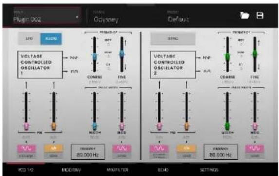
| Parameter | Description | Value | Range | ||
| LFO/Audio | When set to Audio, standard pitches will be produced as indicated by the Oct, Semi and CT values for the Frequency setting.When set to LFO, the VCO will be controlled by an LFO and may be used for modulating VCO2. | LFO, Audio | |||
| Frequency | Determines the pitch adjustment for the oscillator.The total frequency range depends on the LFO/Audio setting, and is shown at the bottom of this section. | 0.174 – 1478.852 Hz | |||
| Coarse | Coarse pitch | adjustment. -0.200 – 6.333 V | |||
| Fine Fine pitch adjustment. | 0.000 – 0.875 V | ||||
| VCO 1 FM Source 1 Waveform | Type of frequency modulation waveform applied by the LFO. | LFO Sine, LFO Square | |||
| Depth 1 Depth of frequency modulation. | 0.0–100.0% | ||||
| Source 2 | Determines the frequency modulation source. | S/H, ADSR | |||
| Depth 2 Depth of Source 2 modulation. | 0.0–100.0% | ||||
| VCO 1 Pulse Width | Width | Width of pulse width modulation. | 50.0–90.0% | ||
| Mod | Depth of pulse width modulation. | 0.0–100.0% | |||
| Source | Determines the pulse width modulation source. | LFO Sine, ADSR | |||
| Sync | Determines whether VCO 2 is synced with the frequency of VCO 1. When disabled, you can use both VCOs to produce separate pitches. | Off, On | |||
| Frequency | Pitch adjustment for the oscillator. | 8.706 – 1478.852 Hz | |||
| Coarse | Coarse pitch | adjustment. -0.200 – 6.333 V | |||
| Fine Fine pitch adjustment. | 0.000 – 0.875 | V | |||
| VCO 2 FM Source 1 | Type of modulation source. When S/H Mixer or Pedal is selected, the modulation can be controlled by the Sample and Hold mixer or by an optional external expression pedal. | LFO Sine, S/H Mixer or Pedal | |||
| Depth 1 Depth of Source 1 modulation. | 0.0–100.0% | ||||
| Source 2 | Type of modulation source. | S/H, ADSR | |||
| Depth 2 Depth of Source 2 modulation. | 0.0–100.0% | ||||
| VCO 2 Pulse Width | Width | Width of pulse width modulation. | 50.0–90.0% | ||
| Mod | Depth of pulse width modulation. | 0.0–100.0% | |||
| Source | Type of source for pulse width modulation. | LFO Sine, ADSR | |||
Mod/Env
Use this tab to adjust the settings for the low frequency oscillator, sample and hold generator, and envelope generator.
| Parameter | Description | Value | |
| LFO | LFO Sync | Determination whether LFO speed is free floating or synced to project tempo. | Off, On |
| LFO Speed | Speed of the low frequency oscillator. | ||
| Sample/Hold | Trigger | Determines the source signal for triggering the Sample and Hold mixer, either the Low Frequency Oscillator or the pitched Keyboard output. | LFO Trigger, Kybd Trigger |
| Source 1 | Selects the VCO-1 waveform or pulse width modulation as Sample and Hold input. | Saw, Pulse | |
| Source 2 | Selects a noise generator or the VCO-2 pulse width modulation as Sample and Hold input. | Noise, Pulse | |
| VCO-1 Level of the VCO-1 input. 0.0–100.0% | |||
| Depth | Level of the noise or VCO-2 input. 0.0–100.0% | ||
| Lag | Adjusts the smoothing of the Sample and Hold output voltage. | 0.0–100.0% | |
| AR | Attack | Attack time of the AR envelope generator. | 0.003 – 10.000 seconds |
| Release | Release time of the AR envelope generator. | 0.003 – 10.000 seconds | |
| Trigger Source | Determines the input source sent to the AR envelope generator.When set to KYBD Gate, the envelope generator is triggered by key input.When set to LFO Repeat, the envelope generator is trigger by the LFO pulse wave. | KYBD Gate, LFO Repeat | |
| ADSR | Attack | Attack time of the ADSR envelope generator. | 0.003 – 10.000 seconds |
| Decay | Decay time of the ADSR envelope generator. | 0.003 – 10.000 seconds | |
| Sustain | Sustain time of the ADSR envelope generator. | 0.000 – 10.000 V | |
| Release | Release time of the ADSR envelope generator. | 0.003 – 10.000 seconds | |
| Trigger Source | Type of input to trigger the envelope generator. | KYBD Gate, LFO Repeat | |
| Repeat | When Trigger Source is set to LFO Repeat, select KYBD Repeat for the LFO to trigger only when a key is pressed, or select Auto Repeat for the LFO to trigger automatically without key input. | KYBD Repeat, Auto Repeat | |
Mix/Filter
Use this tab to adjust the audio mixing and routing, as well as adjust the voltage-controlled filter, high-pass filter, and voltage-controlled amplitude.
| Parameter | Description | Value | |
| VCF VCF Cutoff Cutoff frequency of the filter. 0.680 - 10.645 V, or | 16.02 - 16012.70 Hz | ||
| VCF Res Resonance of the filter. 0.000 - 0.800 Q | |||
| Audio Mixer Noise/Ring Mod | Select the noise generator or ring modulation input for the mixer. | Noise, Ring Mod | |
| Noise/Ring Mod Level | Level of the noise generator or ring modulation into the mixer. | 0.0-100.0% | |
| VCO-1 Input Select the VCO-1 input type for the mixer. Saw, Pulse | |||
| VCO-2 Input Select the VCO-2 input type for the mixer. Saw, Pulse | |||
| VC Filter VCO-1 Filter Modulation Source | Set the input source for VCO-1 filter modulation.Select KYBD CV to use key input as the source.Select S/H Mixer or Pedal to use the Sample and Hold generator or optional external pedal. | KYBD CV, S/H Mixer or Pedal | |
| CV Modulation Level | Level of VCO-1 filter modulation. | 0.0-100.0% | |
| VCO-2 Filter Modulation Source | Set the input source for VCO-2 filter modulation. | S/H, LFO Sine | |
| CV Modulation Level | Level of VCO-2 filter modulation. | 0.0-100.0% | |
| HP Filter Filter Modulation Source | Select which envelope generator to use as a filter modulation source. | ADSR, AR | |
| CV Filter Modulation Level | Amount of envelope filter modulation applied to the VC Filter. | 0.0-100.0% | |
| HPF Cutoff | Cutoff frequency of the high-pass filter. | 0.680 - 10.645 V, or 16.02 - 16012.70 Hz | |
| VC Amp Mod Source | Select which envelope generator to use as an amplitude modulation source. | ADSR, AR | |
| Mod | Amount of envelope modulation applied to the output signal. | 0.0-100.0% | |
| VCA Gain Amount of gain applied to the VC Amp. | 0.0-100.0% | ||
Echo
Use this tab to adjust the settings for the tape echo effect.
| Parameter | Description | Value | Range |
| Delay Use the switch in the bottom-left corner to enable or disable the delay effect. | Off, On | ||
| Sync | Enable to sync the Echo Time to the Global Tempo, or disable to adjust the Echo Time by milliseconds. | Off, On | |
| Sustain Length of time that the echo continues playing. 0.0–100.0% | |||
| Echo Mix Adjusts the wet/dry amount between the original sound and the echo. | 100% Synth – 50/50% – 100% Echo | ||
| Echo Time Amount of time between the dry signal and the delayed signal. Use the slider or the Echo Time field to change the value.When Sync is Off: 0.02 – 5.00 secondsWhen Sync is On: 1/64 – 4/4 | |||
Settings
Use this tab to adjust general settings such as voice count, portamento and performance parameters.
| Parameter | Description | Value Range | |
| Voice Count | Number of voices available. When set to Duo, each VCO controls a separate note. | Duo, 2–4 | |
| Portamento | Length of time to slide between notes. | 0.000 – 1.500 seconds | |
| Exp Pedal | Enables or disables the use of an expression pedal to control portamento. | Off, On | |
| Footswitch | Enable or disables the use of a footswitch to activate portamento. | Off, On | |
| Transpose | Amount of transposition applied to the keyboard. | -2, 0, +2 octaves | |
| Noise | Type of noise used for the noise generator. | White, Pink | |
| Performance Velocity Depth | MW Vib LFO | Amount of vibrato LFO applied by the mod wheel. | 0.0–100.0% |
| MW PWM | Amount of pulse width modulation applied by the mod wheel. | 0.0–100.0% | |
| KYBD Filter | Amount that the filter is tied to the pitch being played. | 0.0–100.0% | |
| KYBD Amp | Amount that the amplitude is tied to the pitch being played. | 0.0–100.0% | |
SATA Drive Installation
To create more internal storage space on your MPC hardware, you can purchase a SATA (Serial ATA) drive and install it yourself, but read this chapter first.
Your MPC X, MPC Live, MPC Live II, or MPC Key 61 can support nearly any standard 2.5" SATA drive on the market—either a solid-state drive (SSD) or hard-disk drive (HDD). Make sure it uses a 2.5" (63.5 mm) form factor and uses (or can use) one of these file systems: exFAT, FAT32, NTFS, or EXT4 (for read and write capability) or HFS+ (for read-only capability).
Note: We recommend using an exFAT file system as it is the most robust one supported by both Windows and macOS.
Note: Alternatively, you could install an mSATA (mini-SATA) drive, but make sure you also purchase an adapter that enables it to fit into a typical 2.5" SATA interface.
- Make sure your MPC hardware is powered off.
- Locate the SATA drive panel in the center of the bottom panel of your MPC hardware. Use a Phillips-head screwdriver to remove the screws (don't lose them!), and remove the SATA drive panel.
- Gently pull the SATA connector and cable out from inside your MPC hardware. Be careful not to disturb anything inside—handle just the SATA connector and cable.
- Connect your SATA drive to the SATA connector. Make sure the connection is secure.
- Use four 3x5mm mounting screws (included with MPC hardware or with your SATA drive) to secure the SATA drive to the SATA drive panel. Do not overtighten the screws, but make sure the drive is secure and does not shake.
- Place the SATA drive panel back onto the bottom panel of your MPC hardware, and use the original screws to secure it in place.
You can now access this drive while using your MPC hardware!
In Standalone Mode, this drive will appear as a second internal drive.
In Controller Mode, this drive will appear as another drive connected to your computer (just as a USB drive or SD card connected does when connected to your MPC hardware).
MIDI Machine Control (MMC)
Your MPC hardware can send and receive MIDI Machine Control (MMC) messages, a standard protocol for transport controls.
The MPC hardware can send these messages:
| MPC Button | MMC Command Sent | |
| Rec | MMC | (when recording starts), then Rebo/MC Record Exit |
| Overdub | MMC | (when recording starts)Rebo/MC Record Exit |
| Stop | MMC | Stop |
| Play MMC Deferred Play | ||
| Play Start MMC Locate Zero, then Deferred Play | ||
| Data Dial, -/+, Step </, Bar <</> MMC Locate values | ||
To set up your MPC hardware to send MMC messages to an external device:
- Use a standard 5-pin MIDI cable to connect your MPC hardware's MIDI Out A to the MIDI input of your external device.
- Press Menu to show the menu, and tap the gear icon to enter the Preferences.
- Tap the Sync tab.
- Tap the Send Port 1 field, and use the data dial or - / + buttons to select Midi Out A.
- Tap the Send MMC box so it is enabled (checked).
- Exit the Preferences.
- Configure your other device properly so it can receive MMC messages.
The MPC hardware can receive these messages:
MPC Command Received MPC Function
| MMC Deferred Play Play | |
| MMC Locate Zero, then Deferred Play Play Start | |
| MMC Stop Stop | |
| MMC Record Strobe Record (Rec) | |
| MMC Pause | Stop |
| MMC Locate values | Change location in sequence |
To set up your MPC hardware to receive MMC messages from an external device:
- Use a standard 5-pin MIDI cable to connect your MPC hardware's MIDI In A to the MIDI output of your external device.
- Press Menu to show the menu, and tap the gear icon to enter the Preferences.
- Tap the Sync tab.
- Tap the Receive MMC box so it is enabled (checked).
- Exit the Preferences.
- Configure your other device properly so it can send MMC messages.
Ableton Control Maps
MPC X / MPC X Special Edition

General Controls and Features
| # | Device Control Ableton Live Function | |
| 1 | Display In Ableton Live | Control Mode, MPC X's display will show a dynamic representation of Ableton Live's software. |
| 2 | Pads | Press the pads to launch clips or scenes. Press the XYFX button to toggle between launching clips (the button is off) and launching scenes (the button is on). |
| 3 | Data Dial Adjusts the highlighted field. | |
| 4 | -/+ Decreases or increases the value of the highlighted field. | |
| 5 | Numeric Input | If the selected field on the screen is a number, press these numbered buttons as you would on a standard numeric keypad to enter a value. Press the keypad's Enter to enter it. (A numeric keypad with additional operations will appear on the screen, as well.) |
| 6 | Directional Cursors Moves the 4x4 Session Matrix focus on the display by one row or one column at a time. | |
| 7 | Shift | Hold this button to access secondary button functions. See Shift Controls for more details. |
Transport Controls
| # | Device Control Ableton Live Function |
| 8 | Record Enable and disable Arrangement Record |
| 9 | Overdub Enable and disable Session Record. |
| 10 | Stop Stop playback. |
| 11 | Play Start playback from the Stop position. |
| 12 | Play Start Start playback from the Arrangement start (1:1:1). |
| 13 | < Move Playhead back by one bar |
| 14 | > Move Playhead forward by one bar |
| 15 | << Phase Nudge down |
| 16 | >> Phase Nudge up |
Right-Hand Side Buttons
| # | Device Control Ableton Live Function | |
| 17 | Tap Tempo Tap this button at the desired rate to set a new tempo in Ableton Live. | |
| 18 | XYFX | Toggles the MPC pads between launching clips (XYFX off) and launching scenes (XYFX on). |
| 19 | Erase | Deletes the selected clip. |
| 20 | Undo | Undo the last action. |
| 21 | Copy | Duplicates the selected clip into the next available clip slot. |
| 22 | Mute | Mutes/deactivates the current track. |
| 23 | Solo | Solos the current track. |
| 24 | Rec Arm Arms the current track for recording. | |
| 25 | Read/Write | Arms Global Automation. |
Left-Hand Side Buttons
| # | Device Control Ableton Live Function | |
| 26 | Next Seq | Opens the Ableton Clip Launch Matrix tab |
| 27 | Ch. Mixer Opens the Ableton Mixer tab. | |
| 28 | Q-Link Project | Moves to the previous device. |
| 29 | Q-Link Program | Moves to the next device. |
| 30 | Q-Link Pad Scene | Device Control Bank Left |
| 31 | Q-Link Pad Param | Device Control Bank Right |
| 32 | Q-Link Screen Control | Opens the Ableton Device Control tab |
| 33 | Q-Links | Adjusts the currently selected parameters displayed in the OLED screens above.Q-Links 1–8 control track volume for the eight tracks currently in view, while Q-Links 9–16 control the device on the currently selected track, based on the "blue hand" in Ableton Live's Detail View. |
Shift Controls
Press and hold MPC X's Shift button, and then press the following buttons for additional actions.
| # | Device Control Ableton | Live Function |
| 2 | Pads Selects a clip without launching it. | |
| 6 | Directional Cursors Moves the 4x4 Session Matrix focus on the display by eight rows or eight columns at a time. | |
| 10 | Stop Stop playback and return song position to 1:1:1. | |
| 17 | Tap Tempo Toggle the metronome on and off. | |
| 21 | Undo Redo the last action. |
MPC Live

Basic Controls
| # | Device Control Ableton Live Function | |
| 1 | Display | In Ableton Live Control Mode, MPC Live's display will show a dynamic representation of Ableton Live's software. |
| 2 | Pads | Press the pads to launch clips or scenes. Press the 16 Level button to toggle between launching clips (the button is off) and launching scenes (the button is on). |
| 3 | Data Dial Adjusts the highlighted field. | |
| 4 | -/+ Decreases or increases the value of the highlighted field. | |
| 5 | Q-Link Button Press this button to move forward between Q-Link Banks 1–4. Push and hold this button to bring up the Q-Links Overview window on the display. | |
| 6 | Q-Links Adjusts the currently selected parameters.Use the Q-Link button to toggle between Q-Link Banks 1 and 2 (which control Track Level for the eight tracks currently viewed) and Banks 3 and 4 (which are mapped to control the device on the current track, based on the location of the "blue hand" in Ableton Live's Detail View). | |
| 7 | Bank A/E Move the 4x4 | Session Matrix focus up by one row. |
| 8 | Bank B/F Move the 4x4 | Session Matrix focus down by one row. |
| 9 | Bank C/G Move the 4x4 | Session Matrix focus left by one column. |
| 10 | Bank D/H Move the 4x4 | Session Matrix focus right by one column. |
| 11 | Erase Deletes the selected clip. | |
| 12 | 16 Level Toggles the MPC pads between launching clips (16 Level off) and launching scenes (16 Level on). | |
| 13 | Shift | Hold this button to access secondary button functions. See Shift Controls for more details. |
| # | Device Control Ableton Live Function |
| 14 | Undo Undo the last action. |
| 15 | Copy Duplicates the selected clip into the next available clip slot. |
| 16 | Tap Tap this button at the desired rate to set a new tempo in Ableton Live. |
| 17 | Rec Enable and disable Arrangement Record. |
| 18 | Overdub Enable and disable Session Record. |
| 19 | Stop Stop playback. |
| 20 | Play Start playback from the current playhead position. |
| 21 | Play Start Start playback from the Arrangement start (1:1:1). |
Shift Controls
Press and hold MPC's Shift button, and then press the following buttons for additional actions.
| # | Device Control Ableton Live Function |
| 2 | Pads Selects a clip without launching it. |
| 5 | Q-Link Button Move backward between Q-Link Banks 1–4. |
| 7 | Bank A/E Move the 4x4 Session Matrix focus up by eight rows. |
| 8 | Bank B/F Move the 4x4 Session Matrix focus down by eight rows. |
| 9 | Bank C/G Move the 4x4 Session Matrix focus left by eight columns. |
| 10 | Bank D/H Move the 4x4 Session Matrix focus right by eight columns. |
| 13 | Undo Redo the last action. |
| 15 | Tap Toggle the metronome on and off. |
| 18 | Stop Stop playback and return song position to 1:1:1. |
MPC Live II

Basic Controls
| # | Device Control Ableton Live Function | |
| 1 | Display | In Ableton Live Control Mode, MPC Live II's display will show a dynamic representation of Ableton Live's software. |
| 2 | Pads | Press the pads to launch clips or scenes. Press the 16 Level button to toggle between launching clips (the button is off) and launching scenes (the button is on). |
| 3 | Data Dial Adjusts the highlighted field. | |
| 4 | -/+ Decreases or increases the value of the highlighted field. | |
| 5 | Q-Link Button Press this button to move forward between Q-Link Banks 1–4. Push and hold this button to bring up the Q-Links Overview window on the display. | |
| 6 | Q-Links Adjusts the currently selected parameters.Use the Q-Link button to toggle between Q-Link Banks 1 and 2 (which control Track Level for the eight tracks currently viewed) and Banks 3 and 4 (which are mapped to control the device on the current track, based on the location of the "blue hand" in Ableton Live's Detail View). | |
| 7 | Bank A/E Move the 4x4 | Session Matrix focus up by one row. |
| 8 | Bank B/F Move the 4x4 | Session Matrix focus down by one row. |
| 9 | Bank C/G Move the 4x4 | Session Matrix focus left by one column. |
| 10 | Bank D/H Move the 4x4 | Session Matrix focus right by one column. |
| 11 | Erase Deletes the selected clip. | |
| 12 | 16 Level | Toggles the MPC pads between launching clips (16 Level off) and launching scenes (16 Level on). |
| # | Device Control Ableton Live Function |
| 13 | Undo Undo the last action. |
| 14 | Copy Duplicates the selected clip into the next available clip slot. |
| 15 | Shift Hold this button to access secondary button functions. See Shift Controls for more details. |
| 16 | Tap Tap this button at the desired rate to set a new tempo in Ableton Live. |
| 17 | Rec Enable and disable Arrangement Record. |
| 18 | Overdub Enable and disable Session Record. |
| 19 | Stop Stop playback. |
| 20 | Play Start playback from the current playhead position. |
| 21 | Play Start Start playback from the Arrangement start (1:1:1). |
Shift Controls
Press and hold MPC Live II's Shift button, and then press the following buttons for additional actions.
| # | Device Control Ableton Live Function |
| 2 | Pads Selects a clip without launching it. |
| 5 | Q-Link Button Move backward between Q-Link Banks 1–4. |
| 7 | Bank A/E Move the 4x4 Session Matrix focus up by eight rows. |
| 8 | Bank B/F Move the 4x4 Session Matrix focus down by eight rows. |
| 9 | Bank C/G Move the 4x4 Session Matrix focus left by eight columns. |
| 10 | Bank D/H Move the 4x4 Session Matrix focus right by eight columns. |
| 13 | Undo Redo the last action. |
| 16 | Tap Toggle the metronome on and off. |
| 19 | Stop Stop playback and return song position to 1:1:1. |
Technical Specifications
Specifications are subject to change without notice.
MPC X / MPC X Special Edition
| Digital Audio System ADCs | 24-bit @ 44.1, 48, or 96 kHz | |
| DACs | 24-bit @ 44.1, 48, or 96 kHz | |
| Digital Signal Processing | 32-bit floating point | |
| Mic Inputs 1-2(2) balanced XLR+1/4"(6.35 mm) TRS | Dynamic Range | 112 dB (A-weighted) |
| SNR | 111 dB (1 kHz, +4 dBu, A-weighted) | |
| THD+N | 0.003% (1 kHz, +4 dBu, -1 dBFS) | |
| Preamp EIN | -135 dBu (max gain, 40 Ω source, A-weighted)-129.5 dBu (max gain, 150 Ω source, unweighted) | |
| Frequency Response | 20 Hz – 20 kHz (+0.2 / -0.2 dB) | |
| Maximum Input Level | +12.5 dBu | |
| Sensitivity | -46 dBu | |
| Gain Range | 58 dB | |
| Line Inputs 1-2(2) balanced XLR+1/4"(6.35 mm) TRS | Dynamic Range | 114 dB (A-weighted) |
| SNR | 112 dB (1 kHz, +4 dBu, A-weighted) | |
| THD+N | 0.003% (1 kHz, +4 dBu, -1 dBFS) | |
| Frequency Response | 20 Hz – 20 kHz (+0.1 / -0.1 dB) | |
| Maximum Input Level | +20 dBu | |
| Sensitivity | -9.5 dBu | |
| Gain Range | 29.5 dB | |
| Line Inputs 3-4(2) balanced 1/4"(6.35 mm) TRS | Dynamic Range | 114.5 dB (A-weighted) |
| SNR | 112.5 dB (1 kHz, +4 dBu, A-weighted) | |
| THD+N | 0.003% (1 kHz, +4 dBu, -1 dBFS) | |
| Frequency Response | 20 Hz – 20 kHz (+0.1 / -0.1 dB) | |
| Maximum Input Level | +20 dBu | |
| Sensitivity | -10 dBu | |
| Gain Range | 30 dB | |
| Inst Inputs 1-2(2) unbalanced 1/4"(6.35 mm) TS | Dynamic Range | 113.5 dB (A-weighted) |
| SNR | 111.5 dB (1 kHz, +4 dBu, A-weighted) | |
| THD+N | 0.003% (1 kHz, +4 dBu, -1 dBFS) | |
| Frequency Response | 20 Hz – 20 kHz (+0.1 / -0.2 dB) | |
| Maximum Input Level | +10 dBu | |
| Sensitivity | -20 dBu | |
| Gain Range | 30 dB | |
| Input Impedance | ~ 1 MΩ | |
| Phono Inputs(2) unbalanced RCA | Dynamic Range | 108 dB (A-weighted, 63 mVrms @ 1kHz, -1 dBFS, 20 Ω source) |
| SNR | 86 dB (A-weighted, 4 mVrms @ 1kHz, 20 Ω source) | |
| THD+N | 0.005% (1 kHz, -46 dBu, -1 dBFS) | |
| Maximum Input Level | 63 mVrms (1 kHz) | |
| Sensitivity | 2 mVrms (1 kHz) | |
| Main Outputs 1-2(2) impedance-balanced 1/4" (6.35 mm) TRS | Dynamic Range | 114 dB (A-weighted) |
| THD+N | 0.006% (1 kHz, -1 dBFS) | |
| Frequency Response | 20 Hz – 20 kHz (+0.0 / -0.2 dB) | |
| Maximum Output Level | +20 dBu | |
| Output Impedance | 100 Ω | |
| Outputs 3-4(2) impedance-balanced 1/4" (6.35 mm) TRS | Dynamic Range | 114 dB (A-weighted) |
| THD+N | 0.006% (1 kHz, -1 dBFS) | |
| Frequency Response | 20 Hz – 20 kHz (+0.0 / -0.2 dB) | |
| Maximum Output Level | +20 dBu | |
| Output Impedance | 100 Ω | |
| Outputs 5-8(4) impedance-balanced 1/4" (6.35 mm) TRS | Dynamic Range | 118.5 dB (A-weighted) |
| THD+N | 0.001% (1 kHz, -1 dBFS) | |
| Frequency Response | 20 Hz – 20 kHz (+0.1 / -0.0 dB) | |
| Maximum Output Level | +20 dBu | |
| Output Impedance | 100 Ω | |
| Headphone Outputs(1) 1/4" (6.35 mm) stereo headphone(1) 1/8" (3.5 mm) stereo headphone | Dynamic Range | 111 dB (A-weighted) |
| THD+N | 0.007% (1 kHz, -1 dBFS, 10 mW/channel into 32 Ω headphones) | |
| Frequency Response | 20 Hz – 20 kHz (+0.0 / -0.2 dB) | |
| Maximum Power Delivered | 360 mW (<1% THD) | |
| Maximum Output Level | +20 dBu | |
| Mechanical | Pads | (16) velocity- and pressure-sensitive pads, RGB-backlit(8) banks accessible via Pad Bank buttons |
| Knobs | (16) 360° touch-sensitive Q-Link knobs for parameter adjustment(7) 270° knobs for gain, mix & level adjustment(1) 360° encoder for value/data adjustment | |
| Display | 10.1" (25.6 cm) full-color 1280x800 display with capacitive multi-touch | |
| Memory | RAM | 2 GB (MPC X)4 GB (MPC X Special Edition) |
| Internal Storage | 16 GB (MPC X) (6 GB user storage)48 GB (MPC X Special Edition) (10 GB user storage)Expandable via SATA connections | |
| File System Compatibility | exFAT (read & write) (recommended)FAT32 (read & write)NTFS (read & write)EXT4 (read & write)HFS+ (read only)Audio Files: AIF/AIFF, FLAC, MP3, OGG, WAV | |
| Connections | (2) XLR+1/4" (6.35 mm) TRS inputs (Input 1/2)(2) 1/4" (6.35 mm) TRS inputs (Input 3/4: 1 stereo pair)(2) 1/4" (6.35 mm) TS instrument inputs (Inst 1/2)(2) RCA inputs (Input 3/4: 1 stereo pair, phono- or line-level)(2) 1/4" (6.35 mm) TS footswitch inputs (FS 1/2)(2) 5-pin MIDI inputs(8) 1/4" (6.35 mm) TRS outputs (Main L/R, Outputs 3/4–7/8: 4 stereo pairs)(4) 5-pin MIDI outputs(8) 1/8" (3.5 mm) CV/Gate outputs(1) 1/4" (6.35 mm) stereo headphone output(1) 1/8" (3.5 mm) stereo headphone output(2) USB Type-A ports(1) USB Type-B port(1) SD card slot(1) power adapter input | |
| Power | via power adapter: 19 V, 3.42 A, center-positive, included | |
| Dimensions(width x depth x height) | 19.9" x 16.7" x 3.4" / 50.5 x 42.4 x 8.7 cm (display flat)19.9" x 15.3" x 8.4" / 50.5 x 38.8 x 21.4 cm (display upright) | |
| Weight | 12.57 lb.5.66 kg | |
MPC Live
| Digital Audio System ADCs | 24-bit @ 44.1, 48, or 96 kHz | |
| DACs | 24-bit @ 44.1, 48, or 96 kHz | |
| Digital Signal Processing | 32-bit floating point | |
| Line Inputs(2) balanced 1/4" (6.35 mm) TRS | Dynamic Range | 113.5 dB (A-weighted) |
| SNR | 108 dB (1 kHz, +4 dBu, A-weighted) | |
| THD+N | 0.001% (1 kHz, +4 dBu, -1 dBFS) | |
| Frequency Response | 20 Hz – 20 kHz (+0.0 / -0.1 dB) | |
| Maximum Input Level | +11 dBu | |
| Sensitivity | -13.5 dBu | |
| Gain Range | 24.5 dB | |
| Phono Inputs(2) unbalanced RCA | Dynamic Range | 107 dB (A-weighted, 63 mVrms @ 1 kHz, -1 dBFS, 20 Ω source) |
| SNR | 86 dB (A-weighted, 4 mVrms @ 1 kHz, 20 Ω source) | |
| THD+N | 0.009% (1 kHz, -46 dBu, -1 dBFS) | |
| Maximum Input Level | 63 mVrms (1 kHz) | |
| Sensitivity | 2 mVrms (1 kHz) | |
| Main Outputs 1–2(2) impedance-balanced 1/4" (6.35 mm) TRS | Dynamic Range | 113 dB (A-weighted) |
| THD+N | 0.002% (1 kHz, -1 dBFS) | |
| Frequency Response | 20 Hz – 20 kHz (+0.0 / -0.5 dB) | |
| Maximum Output Level | +9 dBu | |
| Output Impedance | 100 Ω | |
| Outputs 3–6(4) impedance-balanced 1/4" (6.35 mm) TRS | Dynamic Range | 116 dB (A-weighted) |
| THD+N | 0.001% (1 kHz, -1 dBFS) | |
| Frequency Response | 20 Hz – 20 kHz (+0.0 / -0.1 dB) | |
| Maximum Output Level | +9 dBu | |
| Output Impedance | 100 Ω | |
| Headphone Output(1) 1/8" (3.5 mm) stereo headphone | Dynamic Range | 112 dB (A-weighted) |
| THD+N | 0.005% (1 kHz, -1 dBFS, 10 mW/channel into 32 Ω headphones) | |
| Frequency Response | 20 Hz – 20 kHz (+0.0 / -0.2 dB) | |
| Maximum Power Delivered | +35 mW (<1% THD, 32 Ω headphones) | |
| Maximum Output Level | +10 dBu | |
| Mechanical | Pads | (16) velocity- and pressure-sensitive pads, RGB-backlit(8) banks accessible via Pad Bank buttons |
| Knobs | (4) 360° touch-sensitive Q-Link knobs(4) Q-Link knob columns accessible via Q-Link button(1) 360° encoder for value/data adjustment and selection via push | |
| Display | 7" (17.8 cm) full-color 1280x800 display with capacitive multi-touch | |
| Memory | RAM | 2 GB |
| Internal Storage | 16 GB (6 GB user storage + 10 GB pre-installed content)Expandable via SATA connections | |
| File System Compatibility | exFAT (read & write) (recommended)FAT32 (read & write)NTFS (read & write)EXT4 (read & write)HFS+ (read only)Audio Files: AIF/AIFF, FLAC, MP3, OGG, WAV | |
| Connections | (2) 1/4" (6.35 mm) TRS inputs (1 stereo pair)(6) 1/4" (6.35 mm) TRS outputs (3 stereo pairs)(1) 1/8" (3.5 mm) stereo headphone output(2) RCA inputs (1 stereo pair)(2) 5-pin MIDI inputs(2) 5-pin MIDI outputs(2) USB Type-A ports(1) USB Type-B port(1) SD card slot(1) power adapter input | |
| Power | via power adapter: 19 V, 3.42 A, center-positive, includedvia battery: lithium-ion, rechargeable, up to 6 hours of battery life | |
| Dimensions(width x depth x height) | 16.7" x 8.8" x 2.7"42.4 x 22.4 x 6.9 cm | |
| Weight | 5.9 lb.2.7 kg | |
MPC Live II
| Digital Audio System ADCs | 24-bit @ 44.1, 48, or 96 kHz | |
| DACs | 24-bit @ 44.1, 48, or 96 kHz | |
| Digital Signal Processing | 32-bit floating point | |
| Line Inputs(2) balanced 1/4" (6.35 mm) TRS | Dynamic Range | 113 dB (A-weighted) |
| SNR | 108.5 dB (1 kHz, +4 dBu, A-weighted) | |
| THD+N | 0.001% (1 kHz, +4 dBu, -1 dBFS) | |
| Frequency Response | 20 Hz – 20 kHz (+0.0 / -0.1 dB) | |
| Maximum Input Level | +16.5 dBu | |
| Sensitivity | -13 dBu | |
| Gain Range | 29.5 dB | |
| Phono Inputs(2) unbalanced RCA | Dynamic Range | 108.5 dB (A-weighted, 74 mVrms @ 1 kHz, -1 dBFS, 20 Ω source) |
| SNR | 87 dB (A-weighted, 4 mVrms @ 1 kHz, 20 Ω source) | |
| THD+N | 0.011% (1 kHz, -46 dBu, -1 dBFS) | |
| Maximum Input Level | 74 mVrms (1 kHz) | |
| Sensitivity | 2 mVrms (1 kHz) | |
| Main Outputs 1–2(2) impedance-balanced 1/4" (6.35 mm) TRS | Dynamic Range | 118 dB (A-weighted) |
| THD+N | 0.001% (1 kHz, -1 dBFS) | |
| Frequency Response | 20 Hz – 20 kHz (+0.0 / -0.2 dB) | |
| Maximum Output Level | +9 dBu | |
| Output Impedance | 100 Ω | |
| Outputs 3–4(2) impedance-balanced 1/4" (6.35 mm) TRS | Dynamic Range | 116.5 dB (A-weighted) |
| THD+N | 0.001% (1 kHz, -1 dBFS) | |
| Frequency Response | 20 Hz – 20 kHz (+0.0 / -0.1 dB) | |
| Maximum Output Level | +9 dBu | |
| Output Impedance | 100 Ω | |
| Outputs 5–6(2) impedance-balanced 1/4" (6.35 mm) TRS | Dynamic Range | 112.5 dB (A-weighted) |
| THD+N | 0.002% (1 kHz, -1 dBFS) | |
| Frequency Response | 20 Hz – 20 kHz (+0.0 / -0.1 dB) | |
| Maximum Output Level | +9 dBu | |
| Output Impedance | 100 Ω | |
| Headphone Output(1) 1/8" (3.5 mm) stereo headphone | Dynamic Range | 111 dB (A-weighted) |
| THD+N | 0.003% (1 kHz, -1 dBFS, 10 mW/channel into 32 Ω headphones) | |
| Frequency Response | 20 Hz – 20 kHz (+0.0 / -0.2 dB) | |
| Maximum Power Delivered | +35 mW (<1% THD, 32 Ω headphones) | |
| Maximum Output Level | +10 dBu | |
| Output Impedance | 32 Ω | |
| Pads | (16) velocity- and pressure-sensitive pads, RGB-backlit(8) banks accessible via Pad Bank buttons | |
| Knobs | (4) 360° touch-sensitive Q-Link Knobs(4) Q-Link Knob columns accessible via Q-Link button(1) 360° encoder for display navigation and selection via push | |
| Buttons | (27) dedicated function buttons; red-, amber-, or green-backlit | |
| Display | 6.9" / 176 mm (diagonal)5.9" x 3.7" / 150 x 93 mm (width x height)Full-color LED-backlit display with touch interface | |
| CPU | Processor: Quad-core ARM® processorRAM: 2 GBStorage: 16 GB, expandable via SATA connections | |
| Connections | (2) 1/4" (6.35 mm) TRS inputs (1 stereo pair)(6) 1/4" (6.35 mm) TRS outputs (3 stereo pairs)(1) 1/4" (6.35 mm) stereo headphone output(2) RCA inputs (1 stereo pair)(2) 5-pin MIDI inputs(2) 5-pin MIDI outputs(4) Stereo CV/Gate outputs(1) Ethernet link port(2) USB Type-A ports(1) USB Type-B port(1) SD card slot(1) power adapter input | |
| Power | via power adapter: 19 V, 3.42 A, center-positive, includedvia battery: lithium-ion, rechargeable, up to 4 hours of battery life | |
| Dimensions(width x depth x height) | 16.2" x 9.6" x 1.8"411.5 x 243.8 x 45.7 mm | |
| Weight | 7.45 lbs.3.38 kg | |
MPC One / MPC One+
| Digital Audio System ADCs | 24-bit @ 44.1, 48, or 96 kHz | |
| DACs | 24-bit @ 44.1, 48, or 96 kHz | |
| Digital Signal Processing | 32-bit floating point | |
| Line Inputs 1-2(2) balanced 1/4"(6.35 mm) TRS | Frequency Response | 20 Hz - 20 kHz (+0/-0.8 dB) |
| Dynamic Range | 113 dB (A-weighted) | |
| Signal-to-Noise Ratio | 111 dB (1 kHz, +4 dBu, A-weighted) | |
| THD+N | 0.002% (1 kHz, +4 dBu, -1 dBFS) | |
| Max Input Level | +16 dBu | |
| Sensitivity | -13.5 dBu | |
| Gain Range | 29.5 dB | |
| Line Outputs 1-2(2) balanced 1/4"(6.35 mm) TRS | Frequency Response | 20 Hz - 20 kHz (+0/-0.8 dB) |
| Dynamic Range | 113 dB (A-weighted) | |
| THD+N | 0.003% (1 kHz, -1 dBFS) | |
| Maximum Output Level | +9 dBu | |
| Output Impedance | 100 Ω | |
| Headphone Output(1) 1/8" (3.5 mm) stereo headphone | Frequency Response | 20 Hz - 20 kHz (+0/-0.8 dB) |
| Dynamic Range | 112.5 dB (A-weighted, 32Ω) | |
| THD+N | 0.006% (1 kHz, -1 dBFS, 32Ω) | |
| Maximum Output Level | 28.8 mW @ 32Ω | |
| Mechanical | Pads | (16) velocity- and pressure-sensitive pads, RGB-backlit(8) banks accessible via Pad Bank buttons |
| Knobs | (4) 360° touch-sensitive Q-Link Knobs(4) Q-Link Knob columns accessible via Q-Link button(1) 360° encoder for display navigation and selection via push | |
| Buttons | (31) dedicated function buttons; red-, amber-, or green-backlit | |
| Display | 7.0" / 177 mm (diagonal)5.9" x 3.7" / 151 x 94 mm (width x height)Full-color LED-backlit display with touch interface | |
| CPU | Processor: Quad-core ARM® processorRAM: 2 GBStorage: 2 GB user storage, 2 GB pre-installed content (MPC One)16 GB internal storage, 7.8 GB user storage (MPC One+) | |
| File System Compatibility | exFAT (read & write) (recommended) | |
| FAT32 (read & write) | ||
| NTFS (read & write) | ||
| EXT4 (read & write) | ||
| HFS+ (read only) | ||
| Audio Files: AIF/AIFF, FLAC, MP3, OGG, WAV | ||
| Connections | (2) 1/4” (6.35 mm) TRS inputs (1 stereo pair) | |
| (2) 1/4” (6.35 mm) TRS outputs (1 stereo pair) | ||
| (1) 1/8” (3.5 mm) stereo headphone output | ||
| (1) 5-pin MIDI inputs | ||
| (1) 5-pin MIDI outputs | ||
| (4) CV/Gate outputs | ||
| (1) USB Type-A port | ||
| (1) USB Type-B port | ||
| (1) SD card slot | ||
| (1) power adapter input | ||
| Power | via included power adapter: | |
| MPC One: 19 V, 3.42 A, center-positive | ||
| MPC One+: 12 V, 3 A, center-positive | ||
| Dimensions(width x depth x height) | 10.7” x 10.7” x 2.1” | |
| 272 x 272 x 53 mm | ||
| Weight | 4.7 lbs. | |
| 2.1 kg | ||
MPC Key 61
| Digital Audio System | ADCs | 24-bit @ 44.1, 48, or 96 kHz |
| DACs | 24-bit @ 44.1, 48, or 96 kHz | |
| Digital Signal Processing | 32-bit floating point | |
| Mic Inputs1-2(2) balanced XLR+1/4"(6.35 mm) TRS | Frequency Response | 20 Hz - 20 kHz (+0.2 / -1.0 dB) |
| Dynamic Range | 111 dB (A-weighted) | |
| SNR | 110 dB (1 kHz, +4 dBu, A-weighted) | |
| THD+N | 0.002% (1 kHz, +4 dBu, -1 dBFS) | |
| Preamp EIN | -130 dBu (max gain, 40 Ω source, A-weighted)-128 dBu (max gain, 150 Ω source, unweighted) | |
| Maximum Input Level | +13 dBu | |
| Sensitivity | -46 dBu | |
| Gain Range | 59 dB | |
| Line Inputs 1-2(2) balanced XLR+1/4"(6.35 mm) TRS | Frequency Response | 20 Hz - 20 kHz (+0.2 / -1.0 dB) |
| Dynamic Range | 112 dB (A-weighted) | |
| SNR | 111 dB (1 kHz, +4 dBu, A-weighted) | |
| THD+N | 0.001% (1 kHz, +4 dBu, -1 dBFS) | |
| Maximum Input Level | +20 dBu | |
| Sensitivity | -11 dBu | |
| Gain Range | 31 dB | |
| Inst Inputs 1-2(2) unbalanced 1/4"(6.35 mm) TS | Frequency Response | 20 Hz - 20 kHz (+0.2 / -1.0 dB) |
| Dynamic Range | 112 dB (A-weighted) | |
| SNR | 106 dB (1 kHz, +4 dBu, A-weighted) | |
| THD+N | 0.001% (1 kHz, +4 dBu, -1 dBFS) | |
| Maximum Input Level | +16 dBu | |
| Sensitivity | -15 dBu | |
| Gain Range | 31 dB | |
| Input Impedance | 1 MΩ | |
| Main Outputs 1-2(2) impedance-balanced 1/4" (6.35 mm) TRS | Frequency Response | 20 Hz - 20 kHz (+0.03 / -0.2 dB) |
| Dynamic Range | 115 dB (A-weighted) | |
| THD+N | 0.004% (1 kHz, -1 dBFS) | |
| Maximum Output Level | +16 dBu | |
| Output Impedance | 50 Ω | |
| Outputs 3-4(2) impedance-balanced 1/4" (6.35 mm) TRS | Frequency Response | 20 Hz - 20 kHz (+0.03 / -0.2 dB) |
| Dynamic Range | 115 dB (A-weighted) | |
| THD+N | 0.004% (1 kHz, -1 dBFS) | |
| Maximum Output Level | +16 dBu | |
| Output Impedance | 50 Ω | |
| Headphone Output(1) 1/4" (6.35 mm) stereo headphone | Frequency Response | 20 Hz - 20 kHz (+0.05 / -0.2 dB) |
| Dynamic Range | 108 dB (A-weighted) | |
| THD+N | 0.004% (1 kHz, 10 mW per channel into 32 Ω headphones) | |
| Maximum Output Level | +6 dBu (unloaded) | |
| Power Output | 40 mW RMS (per channel into 32 Ω headphones) | |
| Mechanical | Keys | 61 semi-weighted keys with aftertouch |
| Pads | (16) velocity- and pressure-sensitive pads, RGB-backlit(8) banks accessible via Pad Bank buttons | |
| Knobs | (4) 360° touch-sensitive Q-Link knobs(4) Q-Link Knob columns accessible via Q-Link button(1) 360° encoder for value/data adjustment | |
| Buttons | (44) dedicated function buttons; white-, red-, or green-backlit | |
| Touch | (1) MStripunction, touch-capacitive control strip0.8" x 4.4" / 20 x 113 mm (width x height) | |
| Display | 7" / 177 mm (diagonal)Full-color LED-backlit display with touch interface | |
| Memory | RAM | 4 GB |
| Internal | 32 GBStorageExpandable via SATA connections | |
| File System Compatibility | exFAT (read & write) (recommended)FAT32 (read & write)NTFS (read & write)EXT4 (read & write)HFS+ (read only)Audio Files: AIF/AIFF, FLAC, MP3, OGG, WAV | |
| Connections | (2) 1/4" (6.35 mm) Combo XLR/TRS inputs (1 stereo pair)(1) 1/4" (6.35 mm) TRS sustain pedal input (TS compatible)(1) 1/4" (6.35 mm) TRS footswitch pedal input (TS compatible)(1) 1/4" (6.35 mm) TRS expression pedal input (TS compatible)(4) 1/4" (6.35 mm) TRS outputs (2 stereo pairs)(1) 1/4" (6.35 mm) stereo headphone output(8) 1/8" (3.5 mm) TS mono CV/Gate outputs(1) 5-pin MIDI inputs(1) 5-pin MIDI outputs(1) 5-pin MIDI thru-port(1) Ethernet link port(2) USB Type-A ports(1) USB Type-B port(1) IEC power input | |
| Power | 100 V – 240 V AC, 50/60 Hz, 65 W | |
| Dimensions(width x depth x height) | 38.8" x 12.3" x 3.8"986 x 313 x 96.7 mm | |
| Weight | 17.9 lbs.8.1 kg | |
MPC Key 37
| Digital Audio System ADCs | 24-bit @ 44.1, 48, or 96 kHz | |
| DACs 24-bit @ 44.1, 48, or 96 kHz | ||
| Digital Signal Processing 32-bit floating point | ||
| Line Inputs 1-2(2) balanced 1/4” (6.35 mm)TRS or unbalanced 1/4”(6.35 mm) TS | Frequency Response | 20 Hz - 20 kHz (+0.2/-0.5 dB) |
| Signal-to-Noise Ratio | 107 dB (1 kHz, +6 dBV, A-weighted) | |
| THD+N | 0.004% (1 kHz, +6 dBV, 0 dBFS) | |
| Max Input Level | +12 dBV | |
| Sensitivity | -10 dBV | |
| Gain Range | 27 dB | |
| Line Outputs 1-2(2) impedance-balanced 1/4” (6.35 mm) TRS | Frequency Response | 20 Hz - 20 kHz (+0.2/-0.5 dB) |
| Dynamic Range | 112 dB (A-weighted) | |
| THD+N | 0.004% (1 kHz, 0 dBFS) | |
| Maximum Output Level | +6 dBV | |
| Output Impedance | 100 Ω | |
| Headphone Output(1) 1/8” (3.5 mm) stereo headphone | Frequency Response | 20 Hz - 20 kHz (+0.2/-0.5 dB) |
| Dynamic Range | 112 dB (A-weighted) | |
| THD+N | 0.006% (1 kHz, 10mW per channel into 32Ω) | |
| Maximum Output Level | 40 mW RMS (per channel into 32Ω) | |
| Mechanical | Keys | 37 synth-action keys with aftertouch |
| Pads | (16) velocity- and pressure-sensitive pads, RGB-backlit(8) banks accessible via Pad Bank buttons | |
| Knobs | (4) 360° touch-sensitive Q-Link knobs(4) Q-Link Knob columns accessible via Q-Link button(1) 360° encoder for value/data adjustment | |
| Buttons | (38) dedicated function buttons; white-, red-, or green-backlit | |
| Display | 7” / 177 mm (diagonal)Full-color LED-backlit display with touch interface | |
| Memory | RAM | 2 GB |
| Internal | 32 GB Storage | |
| File System Compatibility | exFAT (read & write) (recommended) FAT32 (read & write) NTFS (read & write) EXT4 (read & write) HFS+ (read only) Audio Files: AIF/AIFF, FLAC, MP3, OGG, WAV | |
| Wi-Fi | Frequency | 2.4 GHz / 5 GHz |
| Standard | 802.11a/b/g/n/ac | |
| Max. | 2.4 GHz WPower17 dBm 5 GHz Wi-Fi: +17 dBm | |
| Bluetooth | Version | 5 |
| Profile | HID, A2DP | |
| Max. | +10 dBm Power | |
| Connections | (2) 1/4" (6.35 mm) TRS inputs (1 stereo pair) (1) 1/4" (6.35 mm) TRS sustain pedal input (TS compatible) (1) 1/4" (6.35 mm) TRS footswitch pedal input (TS compatible) (1) 1/4" (6.35 mm) TRS expression pedal input (TS compatible) (2) 1/4" (6.35 mm) TRS outputs (1 stereo pair) (1) 1/4" (6.35 mm) stereo headphone output (4) 1/8" (3.5 mm) TRS stereo CV/Gate outputs (1) USB Type-A port (1) USB Type-B port (1) 5-pin MIDI input (1) 5-pin MIDI output (1) Power adapter input | |
| Power | via included 12 V, 3 A, center-positive power adapter | |
| Dimensions(width x depth x height) | 22.92" x 12.36" x 4.08" 58.22 x 31.39 x 10.36 cm | |
| Weight | 8.82 lbs. 4 kg | |
Trademarks & Licenses
Akai Professional and MPC are trademarks of inMusic Brands, Inc., registered in the U.S. and other countries.
MPC software incorporates élastique Pro V3 by zplane.development.
Ableton is a trademark of Ableton AG.
The Bluetooth word mark and logos are registered trademarks owned by Bluetooth SIG, Inc., and any use of such marks by Akai Professional is under license.
Kensington and the K & Lock logo are registered trademarks of ACCO Brands.
macOS is a trademark of Apple Inc., registered in the U.S. and other countries.
SD and SDHC are registered trademarks of SD-3C, LLC.
Windows is a registered trademark of Microsoft Corporation in the United States and other countries.
All other product names, company names, trademarks, or trade names are those of their respective owners.
This product contains technologies that are used under license. For more information, please visit akaipro.com/product-legal.
Addenda
MPC Pro Pack
The MPC Pro Pack can be purchased as an upgrade for all Gen 1 MPC standalone hardware running MPC v3.6 or later.
To purchase the MPC Pro Pack, visit thempcstore.com / akaipro.com. You can unlock the Pro Pack on up to three supported devices.
To unlock the Pro Pack, use the Activations tab of the Preferences.
MPC Clip Launching
The MPC Pro Pack brings the full clip-launching workflow of the Akai Force to your MPC. Once the MPC Pro Pack is activated, you must enable Clip Workflow by doing the following:
- Press Menu to open the Menu, and then select Preferences.
- In the Project Defaults tab, tap the Use Clip Workflow box to enable clip workflow.
Turning this feature on or off requires you to restart your MPC hardware. If you have unsaved changes in your project, you will be prompted to save before restarting.
When Clip Launch functionality is activated, you will have access to three additional MPC modes for working with clips:
- Clip Matrix Mode
- Navigate Mode
- Clip Editor Mode
Additionally, the Arrangement Section of Main Mode includes expanded functionality for clips.
When importing an MPC2 project into MPC3 with Clip Workflow enabled, you will be prompted with a Project Import dialog with the following options:
Use the Destination field to select whether to import project data into Sequences or the Clip Matrix.
Use the Import field to select whether to import All Sequences or Selected Sequences. Tap the boxes to select Sequences to import.
Clip Matrix Mode

Clip Matrix Mode gives you an overview of your tracks and clips.
To enter Clip Matrix Mode, press Menu and then navigate to Clip Matrix on the second page of modes and tap it.

Double-tap an empty clip slot to create a new clip. Alternatively, tap and hold on an empty clip slot, and then tap Create.
Tap an existing clip to launch it.
Tap the scene launch icons on the far right of the display to launch a scene.
Tap the + icon at the top of the display to add a new track. If your project already has 8 tracks, move the Matrix view to the right to show this icon.
Tap the Move buttons at the bottom of the touchscreen to move the current matrix display view. To move the display by eight rows or columns at a time, hold Shift and tap the Move 8 buttons.
Tap the Pads: button at the bottom of the touchscreen to change the hardware pad functions:
Select Notes to use the pads in Pad Perform mode to play notes or chords.
Select Clip Launch to use the pads to launch clips. Each pad will represent a clip in the current focus view of the 8x8 Clip Matrix. The focus view will be shown on the screen in a white outline. To move the focus view, tap the Move buttons at the bottom of the screen, or press the Bank buttons on your MPC hardware. This will move the current view by one row or column at a time. You can also press and hold Shift and then tap the Move buttons or press the Bank buttons to move the view by four rows or columns at a time.
Note: The focus view labeling can be adjusted using the Launch Configuration window.
Select Row Launch to use the pads to launch an entire row, or scene. Row 1 will begin with Pad 13, then move left-to-right and down for each available row.
Tap Buses to view the Submixes, Returns, and Output tracks. You can create and launch clips for automation on these tracks using the same methods as tracks, explained below.
The clips in Clip Matrix Mode will change appearance based on their current status:
Stopped, playback stopped
Prepared to record

Stopped, playback active
Recording

Prepared to play

Overdubbing

Playing

Exiting recording
(flashing)
Prepared to stop
To insert a new scene or clear a scene, tap and hold on a Scene Launch button to open the Edit Row window.
Tap Insert to insert one new scene row.
Tap Insert 8 to insert 8 new scene rows.
Tap Insert & Capture to capture any clips currently playing in other scenes and add it to the new scene.
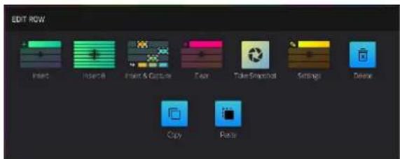
Tap Clear to clear the currently selected scene.
Tap Snapshot to take a snapshot of all automation parameters in each row using the Row Launch buttons. Once a snapshot has been captured to a row, the saved state of all automation settings will be relaunched with the event data on that row. To clear a snapshot from a row, tap Clear Snapshot from the Edit Row window.
Tap Settings to open the Row Settings window.
Tap Delete to delete the currently selected scene, including all clips. All subsequent scenes below this will be moved up.
Tap Copy to copy the currently selected scene and all clips. Once a scene has been copied, tap Paste from the Edit Row window to copy the scene and its contents to the selected row.
To edit track settings, double-tap the track name at the top of the display. See General Features >Tracks for more information on editing track settings. In addition to the settings shown there, an additional Row Launch setting is available. Use this field to determine the behavior of clips in the track when launching scenes. Select Include in row launch to launch the track's clips when launching scenes, or select Exclude from row launch to stop the track's clips from launching with the scene.
The Row Settings window (accessed from the Edit Row window, above) allows you to configure settings for the selected scene.
Use the Name field to rename the row. Tap it and use the virtual keyboard that appears.
Use the Color field to set the row color. Tap the Apply to Clips button to apply this color to all clips in the row.
Check the Set Tempo box to change the sequence tempo when the scene is launched. Use the Tempo field to set the new tempo in beats per minute. If the tempo is set to GBL (global), then row tempo settings will be ignored and the tempo will remain at the global setting.
Use the Follow Action field to apply one of the following behaviors to the row after it is launched. Once a Follow Action is selected, use the Action Time field to set when the action is triggered, in Bars:Beats:Ticks.
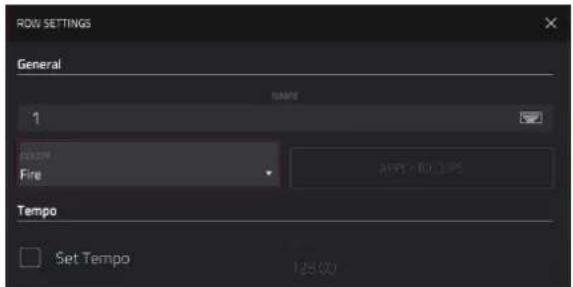

Go To Row: Move to the Row set by the Row field.
To Previous: Move to the previous row. If the scene playing is the first row in the Matrix, playback will stop after the action time is reached.
To Previous or Last: Move to the previous row, or to the last row in the Matrix if the scene playing is the first row in the Matrix.
To Next: Move to the next row. If the scene playing is the last row in the Matrix, playback will stop after the action time is reached.
To Next or First: Move to the next row, or back to the first row if the scene playing is the last row in the Matrix.
To Previously Playing: Move to the last played scene.
To Random (Include This): Move to a random scene, including the one currently playing.
To Random (Exclude This): Move to a random scene, not including the one currently playing.
Back to Arrange: Return to the arrangement after the action time is reached.
Stop: Stop playback after the action time is reached.
Tap the Apply to All Rows field to apply the Follow Action to all rows in the matrix.
Tap the Clear All button to clear all set Follow Actions.
To open the Launch Configuration window, tap the upper-right corner of the display where the BPM and Launch Quantization are located. You can then do any of the following:
Use the Tempo field to set the project tempo. Use the data dial or -/+ buttons to change the tempo, or double-tap the field to open the number pad. Alternatively, use the tap tempo button to set the tempo.
Use the Default Length field to set the default clip length for the project.
Use the Quantization field to set the global quantization amount for launching all clips.

Use the Empty Slots field to determine the appearance of clip launch pads without clips. Select Dim for the pads to be dimly lit in the track color, or Off for the pads to be completely dark.
Check the Tapping a clip selects it box to automatically select a clip when pressed. When enabled, this allows you to instantly view the triggered clip in other modes once tapped. When unchecked, clip focus will remain on the selected pad, which can be chosen by holding Clip Select or Shift and tapping a clip launch pad.
Check the Show arrangement in clip matrix box to view the arrangement row in the clip matrix.
Use the Label Transparency Level slider to adjust the appearance of the Clip Matrix focus view when the pads are in Clip Launch mode.
Check the Only show labels with 'Shift' box to only display the Bank Button direction labels in the focus view while Shift is held.
Tap Close, the X, or outside the window to close the Launch Configuration window and return to Clip Matrix Mode.
You can also tap and hold your finger on a clip slot to quickly access the following functions. For clip slots with clips in them:
Tap Copy to copy the selected clip.
Tap Copy To Arrangement to copy the selected clip contents to the linear arrangement timeline.
Tap Delete to delete the selected clip.
Tap Edit Clip to open the Clip Editor for the selected clip.
Tap Edit Event to open Grid View for the selected clip.
Tap Settings to open the Clip Settings window.
Use the Name field to rename the clip. Tap it and use the virtual keyboard that appears.
Use the Color field to set the clip color.
Use the Launch Quantization field to set the quantization amount for launching the clip.
Use the Launch Mode field to set the clip launch behavior. Select Toggle for the clip to start or stop with each successive press. Select Trigger for the clip to start at the beginning with each press.
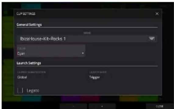
Check the Legato box to enable legato mode for the clip. When enabled, launching the clip will pick up playback from the same position of the previously playing clip, depending on the launch quantization value. For example, if launch quantization is set to 1 bar, launching a legato clip at Bar 1, Beat 2 of another playing clip will cause the legato clip to begin playing at Bar 2, Beat 1. If legato is off, the clip would begin playing from the start.
Tap -/+ at the bottom of the screen to move to the previous or next clip in the track.
Tap Close, the X, or anywhere outside the window to close the Clip Settings window.
For empty clip slots:
Tap Create to create a new clip.
Tap Paste to paste a copied clip.
To open the Record Configuration window, press and hold Record, and then tap Settings.
Check the Write automation when recording box to capture automation while recording.
Use the Record Launch field to set how recording is initiated:
Clip: Tap any clip launch pad while the track is armed to begin recording.
Record or Clip: Tap any clip launch pad while the track is armed to begin recording, or press the Record button to begin recording on the highlighted clip slot.
Record then Clip: First press the record button, then tap any clip launch pad to begin recording
Record to Selection: The record destination automatically updates to the currently selected event list. Whether a clip or the Arrangement is selected, pressing the Record button and then Play will begin recording to the current selection. (This is the default mode when MPC is powered on).
Use the Clip Record To field to set the behavior when recording is completed, entering either Overdub or Play.
Use the Record Arm field to set the arming behavior of the Rec Arm button. When set to Single, MPC automatically record arms the current track when changing tracks and disarms any others. When set to Multi, you can record arm multiple tracks at the same time.
When using Single Record Arm, it is still possible to record arm multiple tracks using the Channel Mixer or Track View Mode.
Check the Fixed Length Recording box to stop recording after the clip length set in the Fixed Length (Bars) field. Leave unchecked to record for any desired clip length.
Tap Close, the X, or outside the window to close the Record Configuration window and return to Clip Matrix Mode.

Navigate Mode

Navigate Mode lets you quickly select which 8x8 grouping of clips is currently in focus in Clip Matrix Mode.
To enter Navigate Mode, press Menu and then navigate to Navigate on the second page of modes and tap it.

natural_image
Colorful pixelated grid pattern with no text or symbolsTo move the matrix view, use your finger to tap or drag to the desired location.
Clip Editor Mode

The Clip Editor lets you view and edit the parameters of the clip container itself. This view has three different appearances: one for audio tracks, one for drum tracks, and one for keygroup, plugin, MIDI and CV tracks.
To enter the Clip Editor, do either of the following:
- Press Menu, press Menu and then navigate to Clip Editor on the second page of modes and tap it.
- Tap Clip at the top of the screen in Arrange Mode, Grid View, or List Edit Mode.
For audio tracks, the waveform of the audio clip is shown.
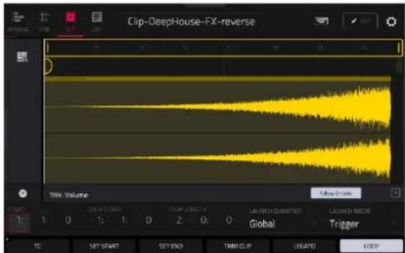
For drum tracks, the left column shows you all available pads in a vertical view with their corresponding events in the grid to the right.
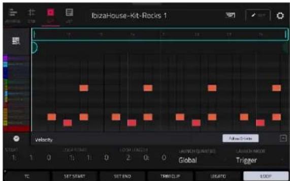
For keygroup, plugin, MIDI and CV tracks, the left column shows a vertical "piano roll" keyboard with the corresponding events in the grid to the right.
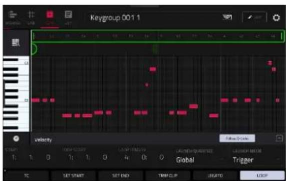
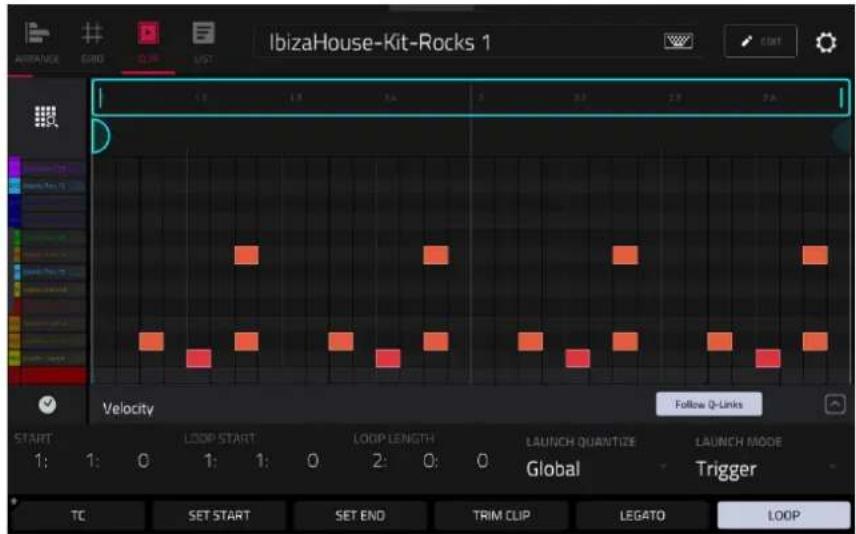
Use the Start fields to set the starting location of the clip when launched. Alternatively, drag the start marker.
Use the Loop Start fields to set the starting location of the clip loop. Alternatively, drag the loop start marker.
Use the Loop Length fields to set the total length of the loop. Alternatively, drag the loop end marker
Use the Launch Quantize field to set the quantization for launching the clip. This can be set separately from the global launch quantization.
Use the Launch Mode field to set how the clip is launched. Select Toggle for the clip to start or stop with each successive press. Select Trigger for the clip to start at the beginning with each press.
Tap TC at the bottom of the screen to open the Timing Correct (TC) window. Alternatively, tap the clock icon next to the automation lane.
Tap Set Start or Set End while the clip is playing to adjust the clip start or end points. The starting point or ending point will be set at the playhead location.
To trim a clip, use the Loop Length fields to set the preferred length, then tap Trim Clip to trim the whole clip to this size.
Tap Legato to enable or disable legato. When Legato is active, the playhead will continue from the same position as it was in the previous clip of the same track when switching between clips. This is useful for creating seamless fills in drum breaks or when using an a capella track.
Tap Loop to toggle the clip loop on or off. Generally, turn Loop on for complete phrases and turn it off for one shots.
To shift the entire loop area left or right, press and hold Shift and tap << Loop or Loop >>.
To halve or double the loop size, press and hold Shift and tap /2 or 2X.
Tap the up arrow (∧) button in the lower-right corner to view the velocity/automation lane. Velocity and automation can be edited in Grid View. To hide the velocity/automation lane, tap the down arrow (∨) when it is expanded. Tap the Follow Q-Links button to automatically update the current automation parameter to the selected Q-Link parameter.
The Settings window lets you configure certain Grid View settings.
To view the Settings, tap the gear icon.
Main Mode – Arrangement & Clip Section
The Arrangement & Clip section displays recorded events from the linear arrangement timeline or the selected clip and provides easy access to their editing functions.

The Arrangement & Clip header shows either the arrangement or the selected clip number and name.
To change clips, tap the Arrangement & Clip header and use the data dial or +/- buttons. You can also press and hold Shift and tap the Clip -/+ buttons at the bottom of the screen.
Press and hold Shift to access these additional Function button options at the bottom of the screen:
Back to Arr: Tap this button to return the selected track back to arrangement playback.
All Track to Arr: Tap this button to return all tracks back to arrangement playback.
Clip -/+: Tap one of these buttons to switch to the previous or next clip, respectively.
Clip Stop: Tap this button to stop the current clip from playback.
Stop All: Tap this button to stop all clips from playback.
Arrangement
Tap and hold on the Arrangement icon to access the following functions:
Tap Copy Arrangement To Clip to copy the linear arrangement for the current track to a new clip. Use the window that appears to select the clip slot destination, and then tap Do It to continue, or Cancel to return to the previous page.
Check the Launch selected clip during playback option to enable automatically launching selected clips or the arrangement when selected. This can be used in conjunction with Legato mode to vary clips in real time with fills.
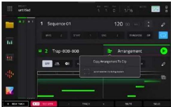
Clips
Tap the Clip Number in the header to access the following clip edit actions.
For clip slots with clips in them:
Tap Copy to copy the selected clip.
Tap Copy To Arrangement to copy the clip contents to the linear arrangement.
Use the Position Bar field to select where in the timeline the clip should be added.
Select Replace to replace contents of the arrangement with the clip contents at the selected location.
Select Merge to add the clip contents to the existing arrangement content at the selected location.
Tap Delete to delete the selected clip.
Tap Edit Clip to open the Clip Editor.
Tap Edit Event/Edit Region to open Grid View.
Tap Settings to open the Clip Settings window (explained below).
Tap Flatten Clip or Flatten Clip Elastique to flatten an audio clip, rendering all the edits and regions within the arrangement to a single new audio file. The Elastique Pro algorithm can be used for time-stretching or pitch-shifting, providing higher-quality results with less artifacts than Force's standard algorithm.
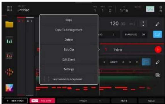
For empty clip slots:
Tap Create to create a new clip.
Tap Paste to paste a copied clip.
For both filled and empty clip slots:
Check the Launch selected clip during playback option to enable automatically launching clips when selected. This can be used in conjunction with Legato mode to vary clips in real time with fills.
To edit clip settings, tap and hold on the clip name and then tap Settings:
Use the Name field to rename the clip. Tap it and use the virtual keyboard that appears.
Use the Color field to set the clip color.
Use the Launch Quantization field to set the quantization amount for launching the clip.
Use the Launch Mode field to set the clip launch behavior. Select Toggle for the clip to start or stop with each successive press. Select Trigger for the clip to start at the beginning with each press.

Check the Legato box to enable legato mode for the clip. When enabled, launching the clip will pick up playback from the same position of the previously playing clip, depending on the launch quantization value. For example, if launch quantization is set to 1 bar, launching a legato clip at Bar 1, Beat 2 of another playing clip will cause the legato clip to begin playing at Bar 2, Beat 1. If legato is off, the clip would begin playing from the start.
The appearance of the clip section changes based on whether there is a loaded clip or not.

For filled clip slots:
Tap the play icon to begin playback of the clip.
Use the Start fields to set the starting location of the clip when launched. Alternatively, drag the start marker.
Use the Loop Start fields to set the starting location of the clip loop. Alternatively, drag the loop start marker.
Use the Loop Length fields to set the total length of the loop. Alternatively, drag the loop end marker.
Tap Loop to toggle the clip loop on or off. Generally, turn Loop on for complete phrases and turn it off for one shots.
Double-tap on the clip timeline to open Grid View displaying the current clip.
Tap the duplicate icon to immediately duplicate the clip to the next empty clip slot on the current track.
When an audio track is selected, tap the tuning fork icon to open the Tuner.

For empty clip slots:
Tap the + icon in the header to create an empty clip in the current slot. Alternatively, tap Create Clip in the clip area below.
When Clip Recording is armed, this will turn into a record icon. Tap it to begin recording a new clip in the current slot. Alternatively, tap Record in the clip area below. Once recording begins, the clip area will switch to the filled clip appearance.
Set the Fixed Length Recording field to On to stop recording after the clip length set in the Default Length (Bars) field. Set to Off to record for any desired clip length.
When an audio track is selected, tap the tuning fork icon to open the Tuner.
Tap the pencil icon to open the Clip Edit options for the selected clip.
The following functions are available for all track types:
The Clear function erases all events from the clip.
Tap Clear to confirm your choice.
Tap Cancel to return to the previous screen.
The Half clip function immediately reduces the clip length by half.

The Double clip function immediately doubles the clip length, without doubling the events or regions in the clip.
The Double length with events function immediately doubles the clip length along with all clip events or regions.
The Double Length with Events function immediately doubles the length of the clip and duplicates the events.
The Trim to length function immediately trims any clip events or regions from outside the clip length.
The following functions are available for all track types except Audio:
The Half-Speed function immediately doubles the lengths of all note events in the clip as well as the distance between them. In other words, all notes are spread further apart so the clip sounds like it is playing at half of the previous speed. This does not actually affect the pitches of notes or the tempo.
The Double-Speed function immediately halves the lengths of all note events in the clip as well as the distance between them. In other words, all notes are pressed closer together so that the clip sounds like it is playing at twice the previous speed. This does not actually affect the pitches of notes or the tempo.
The Pitch Quantize function forces the pitches of MIDI note events into a specific scale.
Use the Root Note field to select the desired root note of the scale.
Use the Scale field to select a type of scale.
To determine which note events will be quantized, tap the Only apply to selected events checkbox.
When on, only the currently selected note events will be quantized.
When off, all pitches in the current track will be quantized.
Use the Start Note and End Note fields to set lowest-possible and highest-possible pitches where the quantized note events will be placed (respectively). If a note event is originally outside of this range, it will be forced to the nearest pitch (within the scale) inside the range.
Tap Do It to confirm your choice, or tap the X, Cancel, or anywhere outside the window to cancel and return to the previous screen.

The Humanize function applies randomization to the timing, length, and/or velocity of note events.
Tap the Humanize Time checkbox to select whether or not humanization will be applied to the timing of note events.
Use the Amount (Pulses) slider to select the maximum number of pulses by which the timing of an event will be adjusted.
Use the Eagerness slider to set how dramatically the humanization effect is applied to the timing. Negative values correspond to playing “ahead of the beat” while positive values correspond to playing “behind the beat.”
Tap the Humanize Note Length checkbox to set whether or not humanization will be applied to the duration of note events.
Use the Length (%) slider to set how dramatically the humanization effect is applied to note lengths.
Tap the Humanize Velocity checkbox to set whether or not humanization will be applied to the velocities of note events.
Use the Strength (%) slider to set how dramatically the humanization effect is applied to note velocities.
Tap the Only Apply to Selected Events checkbox to determine which notes will use these humanization values:
When on, just the currently selected notes will be humanized.
When off, all notes in the arrangement will be humanized.
Tap Apply to apply humanization and keep this window open.
Tap Do It to apply humanization and close the window.
Tap Close, the X, or anywhere outside the window to close the window without making any changes.


The Random Events function creates random melodic or drum patterns in the current clip.
Use the Event Type field to select Drum Events or Melodic Events to select the type of events you want to create.
Use the Replace field to select how the events will be created relative to the existing events on the track:
Replace All Events: Select this option to replace all events in the arrangement with the randomly generated ones.
Replace Events in Note Range: Select this option to replace all events in the designated note range in the clip with the randomly generated ones. Use the Bank or Start Pad and End Pad menus to set the note range for drum events or the Start Note and End Note menus to set the note range for melodic events.
Add to Existing Events: Select this option to add the randomly generated events to the clip without replacing or overwriting the existing ones.
Use the Pattern Size (Bars) field to set how many bars the events will use. The highest possible value is the number of bars in the current clip.
Use the Note Length field to select the duration of the events. (This feature is nonfunctional if Legato is enabled while generating melodic events.)
Tap Apply to generate the events and keep this window open.
Tap Do It to generate the events and close the window.
Tap Close, the X, or anywhere outside the window to close the window without generating any events.

The Split Events process divides note events into an equal number of parts.
Use the Into slider to select the number of parts the event(s) will be split into.
Tap the Only selected events checkbox to apply the process only to currently selected events. When unchecked, all events will be split.
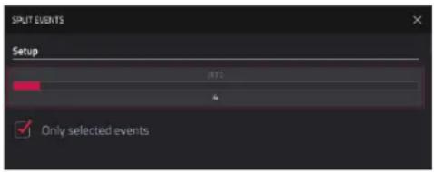
The Convert to Progression function creates a custom Progression from a melodic MIDI track that you can use to perform with Progressions Note mode.
Use the Progression fields to set the parameters of the new Progression:
Use the Name field to set the progression name.
Use the Root Note field to set the root note.
Use the Scale Type field to set the scale type.

Use the Chord fields to set the parameters for the chords in the Progression:
Use the Chord field to select a chord from the progression to edit.
Use the Name field to rename the selected chord.
Use the Type field to set the type of chord: Root, Normal or Below Root.
Tap the Play button to play the selected chord.
Tap Do It to convert the progression and close the window.
Tap Close, the X, or anywhere outside the window to close the window and return to the previous screen.
The following functions are available for Drum, Keygroup, Plugin, and Audio tracks:
The Bounce to Sample function renders the current clip as an audio sample and places it in the project's sample pool. By default, it will be named Bounce and appended with the track name.
Use the Audio Tail field to set the amount, in seconds, of extra time added to the end of the resulting audio files.
The Bounce to Audio Track function renders the current clip and adds it as a new audio track in the project. The Main Mode view will automatically switch to the Audio tab. By default, it will be named Bounce and appended with the track name. This function does not work for MIDI tracks or CV tracks.
Use the Audio Tail field to set the amount, in seconds, of extra time added to the end of the resulting audio files.
The following functions are available for Audio tracks only:
The Flatten and Flatten Elastique functions flatten the audio clip, rendering all the edits and regions within the arrangement to a single new audio file. The Elastique Pro algorithm can be used for time-stretching or pitch-shifting, providing higher-quality results with less artifacts than Force's standard algorithm.
Advanced CV Track Edit
The MPC Pro Pack includes an advanced CV track editing playground, with a comprehensive set of modulators and utilities to greatly enhance control over CV-enabled devices.
Routing
In the Routing tab, you can set the routing options for the CV outputs.
Note: Changes made on this screen replace CV settings in Main Mode. You can dismiss this message at the top of the screen by tapping the i icon.

Use the CV field to select a routing destination for each CV Out.
Use the Out knobs to set the output voltage.
Use the Depth knob to apply additional modulation depth to the output.
Env 1-4
Tap Envelopes to cycle through its four tabs for the available envelopes which can be used to create a variable control signal to modulate the filter, amplitude, or pitch settings of a sound over a given period of time. You can also tap on the Env 1-4 headers to switch between pages.
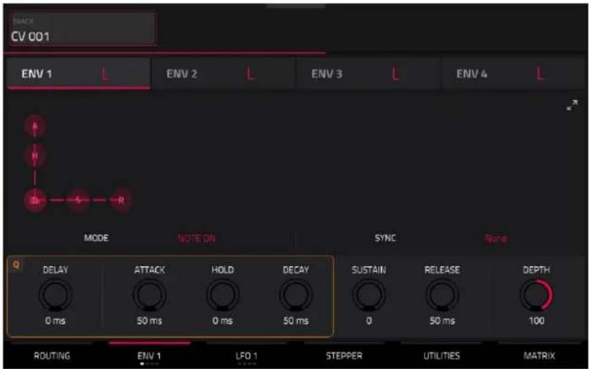
Use the Mode field to select how the envelope is triggered. Select Note On to restart the envelope with each Note On message. Select Loop to continuously cycle the envelope. Select One Shot to play through the envelope once.
Use the Sync field to synchronize the envelope to the MPC sequence for precise timing control.
Use the Delay, Attack, Hold, Decay, Sustain, and Release fields or click and drag the "handles" of each envelope to shape the envelope or time-variant modulation output. See the Anatomy of an Envelope section to learn about the envelope parameters.
Use the Depth knob to set the overall amount and direction in which the envelope is applied.
LFO 1-4

Tap LFO to cycle through its four tabs for the available LFOs, which can be used to generate a periodic waveform with an adjustable frequency and shape for modulation purposes. You can also tap on the LFO 1-4 headers to switch between pages.
Use the Type field to select the LFO waveform type: Ramp Up, Ramp Down, Triangle, Sine, Square, Random 1, Random 2.
Use the Trigger field to determine how the LFO phase resets. Select Free Running for the LFO to run continuously without resetting. Select Play Start to reset the LFO at the start of the sequence. Select Note On to reset the LFO each time a note is triggered in the CV track's grid.
Use the Rate knob to determine the LFO frequency. At lower values, it might take some time for the LFO to complete a cycle, while higher values will come closer to audible range.
Use the Sync knob to synchronize the LFO's rate with the MPC sequence tempo. You can select one of several time divisions (a . indicates a dotted note; a T indicates a triplet-based time division). When None is selected, Sync is off, and the frequency is determined by the Rate knob.
Use the Depth knob to set the overall amount of modulation applied by the LFO. At lower values, the modulation is more subtle, and at higher values it is more extreme.
Stepper
The Stepper section lets you create a step sequence for CV control.

Use the Steps field to set the length of the sequence.
Use the Speed field to set how quickly the sequence is played.
Use the Speed Sync field to synchronize the speed with the MPC sequence tempo. You can select one of several time divisions (a . indicates a dotted note; a T indicates a triplet-based time division). When set to None, Sync is off, and the sequence timing is determined by the Speed field.
Tap and drag the step handles to set step values.
Tap and drag the smoothing values, above the step number, to apply additional smoothing to each step.
Utilities

The Ramp section lets you create rising or falling modulation signals.
Use the Time fields to adjust the length of the ramps.
Use the Shape fields to adjust the curve of the ramps. Positive values rise or fall more quickly, while negative values rise or fall more slowly.
Use the Offsets knobs to adjust voltage levels to modulate external gear.
The Clock Divider section divides the incoming clock to allow for slower modulation rates.
Use Step Time knobs to set Step lengths for modulation purposes.
Matrix
The Matrix section allows you to modulate different sources and sum or multiply them for complex signals.

Q-Link Edit – Envelope Follower / LFO
In the Envelope Follower / LFO tab of Q-Link Edit mode, you can use an audio signal (such as a kick drum) as a control signal to create side-chain or modulation effects.
There are 16 available envelope followers, which can be selected using the Control field at the top left of the touchscreen.
Tap the On button next to the Envelope Source field to enable or disable the envelope.
Use the Envelope Source field to select the audio signal that will be used as the control signal for the envelope. This can be audio from a Track, or audio from a specific Pad (for Drum tracks) or Keygroup (for Keygroup tracks). You can also select the Returns, Submixes, and Main Output tracks, as well as dedicated LFO (low frequency oscillator) shapes.
After selecting the Envelope Source, you can use the additional fields on the left side of the touchscreen to configure the envelope parameters. The available parameters when a track, pad or keygroup is selected as the Envelope Source are as follows:
Use the selector below the Envelope Source field to set where the envelope is applied:
- Input: The envelope is applied at the audio input source. This option is only available for MIDI and CV tracks.
• Pre-Inserts: The envelope is applied before any insert effects. - Post-Fader: The envelope is applied at the end of the channel strip after any insert effects and after the set volume level.
- Playback: The envelope is applied on playback of the selected track. This option is only available for MIDI and CV tracks.
Use the knobs below the envelope selector to adjust the parameters of the envelope. Tap the arrows to move between the pages of parameters when applicable.
• Gain (%) adjust the amount of gain applied to the envelope.
- Delay (ms) adjusts the amount of delay in milliseconds after which the envelope is triggered.
• Gate (%) adjusts the amount of gate applied to the envelope
• Hyst (%) adjusts the level at which the gate closes after opening.
- Attack adjusts the amount of attack for the envelope gate. This can also be adjusted by tapping and dragging the A handle in the envelope display.
- Decay adjusts the amount of decay for the envelope gate. This can also be adjusted by tapping and dragging the D handle in the envelope display.
When LFO is selected as the Envelope Source, the available parameters are as follows:
Use the selector to configure how the LFO is applied to the envelope. Select Free-Running for the LFO to continue even when not triggered, or select Reset On Play for the LFO to revert to its starting configuration when triggered.
Use the knobs below the selector to adjust the parameters of the LFO:
• Freq (Hz) adjusts the frequency, in Hertz, of the LFO.
• Phase (°) adjust the starting phase of the LFO.
• Level (%) adjusts the amount of LFO applied.
When the LFO envelope is engaged, you will see a representation of the LFO signal.
Once you have configured the envelope follower source, use the right side of the screen to select the parameter(s) that it will modulate using the same directions as described in Q-Link Edit > Editing Macro Assignments.
Super Warp Algorithm
MPC Pro Pack includes a new Super Warp algorithm, offering high-quality FFT-based time stretching and pitch shifting.
To use the Super algorithm, open the Preferences menu and navigate to the Audio/Export tab, then set the Default Warp Algorithm setting to Super. Your choice of algorithm will be saved and recalled with the project, track, or program files.
The Warp algorithm can also be adjusted individually in the Samples tab of Track Edit Mode for Drum Tracks, or in Grid View for Audio Tracks.
Pro Pack Plugins
The MPC Pro Pack includes three new Insert effects:
- AIR Visual EQ4 is a highly versatile EQ plugin providing four bands of equalization with a wide range of EQ types. The spectrum analyzer also provides clear visual feedback of the audio you are processing.
- AIR Reverb Pro delivers realistic, dynamic reverbs suitable for a variety of sound design tasks, from subtle room reverbs to rich, expansive modulated tails.
Note: When used with standalone MPC, AIR Reverb Pro is limited to four instances.
• AIR Utility provides all your basic gain, mono, and stereo utility needs in a single plugin.
The MPC Pro Pack also includes the AIR Fabric Select instrument plugin. Fabric Select gives you access to all of the bread and butter sounds you need. Fabric Select has been built from Fabric XL using a smaller selection of its incredible sounding sample keymaps.
AIR Visual EQ4

Parameter
Description
Value
Range
| Band Tap the power button next to each band to turn it on or off. Off, On | ||
| Freq Center frequency of the EQ band. 20.0 Hz – 20.00 kHz | ||
| Gain | When Type is set to LowShelf, Peak, or HighShelf, this adjusts the output level of the IEQ band. | -30.0 – 0.0 – +30.0 dB |
| Q Width of the EQ band. 0.10 | -18.00 | |
| Type Shape of the selected EQ band. LowShelf, LowPass, | HighPass, BandPass, Notch, Peak, HighShelf | |
| Gain Output level of the post-EQ audio. -inf – 0.0 – +12.0 dB | ||
AIR Reverb Pro
Main

| Parameter | Description | Value Range |
| Room Size | Size of the simulated room which helps determine the reverberation length. | XXXXS, XXS, XS, S, M, L, XL, XXL, XXXL |
| Pre-Delay Length of time between dry signal and reverberated signal.Tap themusic note iconto enable or disableSync.WhenSyncis Off:0–250 msWhenSyncis On:0, 1/32, 1/16T, 1/32D, 1/16, 1/8T, 1/16D, 1/8, 1/4T, 1/8D, 1/4, | ||
| Decay Rate at which the reverberation decays after the original direct signal stops. | 0–100% | |
| Mix Wet/dry amount of the reverb effect. 0–100% | ||
| Balance Mix between the Early Reflections signal and Tail signal. 0–100% | ||
| Input Width Adjusts the spread of the incoming audio signal in the stereo field. A setting of 0% means the incoming audio will be processed in mono. A setting of 100% means the incoming audio will be processed as a full stereo image. | 0–100% | |
| Output Width Adjusts the spread of the outgoing processed audio signal in the stereo field. A setting of 0% means the audio will be output in mono. A setting of 100% produces an open, panned stereo image. | 0–100% | |
Early Reflections

Parameter Description Value Range
Type Simulated physical environment used for modeling the early reflections. See Description
• Off: No early reflections.
- Booth: Simulates a vocal recording booth.
• Club: Simulates a small, clear, natural-sounding club ambience.
• Room: Simulates the center of a small room without many reflections.
• Small Chamber: Simulates a bright, small-sized room.
• Medium Chamber: Simulates a bright, medium-sized room.
• Large Chamber: Simulates a bright, large-sized room.
• Small Studio: Simulates a small, live, empty room.
• Large Studio: Simulates a large, live, empty room.
• Scoring Stage: Simulates a scoring stage in a medium-sized hall.
- Philharmonic: Simulates the space and ambience of a large, symphonic, concert hall.
• Concert Hall: Simulates the space and ambience of a large concert hall.
- Church: Simulates a medium-sized space with natural, clear-sounding reflections.
• Opera House: Simulates the space and ambience of an opera house.
• Vintage 1: Simulates a vintage digital reverb effect.
• Vintage 2: Simulates a vintage digital reverb effect.
Direct Incoming audio level of the unprocessed signal into the Early Reflection. -inf - 0.0 dB
Pre-Delay Incoming audio level of the Pre-Delay processed signal into the Early Reflection. -inf - 0.0 dB
Scale Adjusts the size of the early reflection reverb. You can also click and drag the cube to adjust the size. -50.0 - 400.00%
Tail

Parameter Description Value Range
| Tail Distance | Adjusts the distance that sound travels for reflections during the tail. The higher the distance, the more you can hear distinct reflections in the tail. | 0-100% | |
| Density | Adjusts the rate at which the sound density of the reverb tail increases over time. Higher Density settings create a smoother reverberated sound. Lower settings result in more fluttery echo. | 0-100% | |
| Input Direct | Incoming audio level of the unprocessed signal into the Tail. | -inf - 0.0 dB | |
| Pre-Delay | Incoming audio level of the Pre-Delay processed signal into the Tail. | -inf - 0.0 dB | |
| Early Reflections | Incoming audio level of the Early Reflections processed signal into the Tail. | -inf - 0.0 dB | |
| Mod On/Off | Tap the switch in the upper-right corner of this section to enable modulation. | Off, On | |
| Mod - Depth | Amount of modulation applied to the Tail processed signal | 0-100% | |
| Mod - Rate | Speed of modulation applied to the Tail processed signal. | 0-100% | |
| Damping | Low | Center frequency at which low-frequency damping is applied to the Tail signal. | 10-2000 Hz |
| Early | Center frequency at which high-frequency damping is applied to the early Tail reverberations. | 500-30000 Hz | |
| Late | Center frequency at which high-frequency damping is applied to the late Tail reverberations. | 500-30000 Hz | |
EQ/Dynamic

| Parameter | Description | Value | Range | |
| EQ On/Off | Tap the switch next to the EQ heading to turn it on or off. | Off, On | ||
| Low Cut | Center frequency of the low cut filter. 10.0 Hz - 1.00 kHz | |||
| Low Freq | Center frequency of the low EQ band. 20.0 Hz - 1.00 kHz | |||
| Low Gain | Level of the low EQ band. -15.0 - 0.0 - +15.0 dB | |||
| Mid Freq | Center frequency of the mid EQ band. 40.0 Hz - 16.0 kHz | |||
| Mid Gain | Level of the mid EQ band. | -15.0 - 0.0 - +15.0 dB | ||
| Mid Q | Width of the mid EQ band. | 0.50 | -10.00 | |
| High Mid Freq | Center frequency of the mid EQ band. | 40.0 Hz - 16.0 kHz | ||
| High Mid Gain | Level of the mid EQ band. | -15.0 - 0.0 - +15.0 dB | ||
| High Mid Q | Width of the mid EQ band. | 0.50-10.00 | ||
| High Freq | Center frequency of the high EQ band. 2.00 - 20.0 kHz | |||
| High Gain | Level of the high EQ band. | -15.0 - 0.0 - +15.0 dB | ||
| High Cut | Center frequency of the high cut filter. | 200 Hz - 20.0 kHz | ||
| Compressor | Tap the switch next to the Compressor heading to turn it on or off. | Off, On | ||
| Threshold | Volume level at which compression will be applied. | -40.0 - 0.0 dB | ||
| Gain | Adjusts the output level of the compressed signal. | 0.00-30.00 | ||
AIR Utility

Parameter
Description
Value
Range
Input Left Phase Tap to invert the phase of the left stereo channel. Off, On
Right Phase Tap to invert the phase of the right stereo channel. Off, On
Mode Tap the drop-down menu to adjust the Stereo processing mode.
See Description
• L: Left channel only
- L+R (-3dB): Summed left and right channels, with a -3 dB pad.
- L+R (-6dB): Summed left and right channels, with a -6 dB pad.
• L-R (+3dB): Inter-channel difference, with a -3 dB pad.
• L-R (+6dB): Inter-channel difference, with a -6 dB pad.
• R: Right channel only
- Stereo: Standard stereo image
- Swapped: Reverses the left and right stereo channels
Mono Converts a Stereo signal to Mono. This is only available when
Off, On
Type is set to L-R (+3dB), L-R (+6dB), Stereo, or Swapped.
Mid-Side Enables Mid-Side encoding, where the Left + Right channel
Off, On
sum is centered in the stereo image, and the Left - Right channel difference is panned to each side. This is only available when Type is set to Stereo or Swapped.
Width Adjusts the stereo width of the input signal. Higher values give
0–200%
wider stereo separation.
Bass
Mono
Enable the low frequency counter signal to mono.
Off, On
Bass
CentAmfrequency of the low-pass filter used for the Bass Mono function.
50 - 500 Hz
Frequency
Bass
Tap the headphones icon to isolate the low frequencies, useful when adjusting the Bass Mono Frequency.
Off, On
Audition
Parameter
Description
Value
Range
Output Mute Mutes the outgoing audio. Off, On
| DC Offset Applies a high-pass filter to remove extreme low frequencies that may cause audio issues. | Off, On | |
| Gain | Adjust the output level of the processed signal. | -inf - 0.0 - 25.0 dB |
| Pan | Adjust the stereo panning of the output signal. | L (100:0) - C (0:0) - R (0:100) |
AIR Fabric Select
The all-new AIR Fabric Select is a streamlined edition of AIR Fabric, offering a curated selection of its most popular and versatile patches. AIR Fabric Select is perfect as an introduction of Fabric's sound palette, with fewer presets but the same high-quality sound engine you know from the full version.
Main / Perc / Settings
Use this tab to select layer sounds and adjust main layer parameters, add a percussion layer, and edit global settings. Tap the tab to cycle between the three pages.

Main
| Parameter | Description | Value | |
| Layer 1/2 Pan | Stereo pannin | g of the layer. L64 - | - C – R64 |
| Volume | Level of the layer. | 0–100% | |
| Category | Sound category of the layer. | Varies | |
| Preset | Preset sound within the selected category. | Varies | |
| Enable/Disable | Enable or disable the layer. | Off, On | |
| Cutoff | Filter cutoff frequency of the layer. | -100 – 0 – +100% | |
| Reso | Amount of resonance/emphasis of the filter cutoff point for the layer. | -100 – 0 – +100% | |
| Attack | Amount of amplitude attack reduced from or added to the sound. | -100 – 0 – +100% | |
| Release | Amount of amplitude release reduced from or added to the sound. | -100 – 0 – +100% | |
| Formant | Decreases or increases resonant frequencies to adjust the timbre of the sound. | -100 – 0 – +100% | |
| Sample Start | Starting point of the sample. | -100 – 0 – +100% | |
| Delay | Enable or disable the delay effect. | Off, On | |
| Delay Mix | Wet/dry amount of the delay effect. 0–100% | ||
| Reverb | Enable or disable the reverb effect. | Off, On | |
| Reverb Mix | Wet/dry amount of the reverb effect. | 0–100% | |
Perc

| Parameter | Description | Value |
| Percussion | Enables or disables percussion sample. Off, On | |
| Sample | Select the percussion sample used. | Varies |
| Trigger | Selects when the percussion sample is triggered. | Note-On, Note-Off |
| Octave | Adjust pitch of the percussion sample. -4 – 0 – +4 | |
| Cutoff | Cutoff frequency of the percussion sample. 0–100% | |
| Decay | Length of time for the percussion sample to decay. | 0.0 ms – 32.0 s |
| Release | Length of time for the percussion sample to become silent after being released. | 0.0 ms – 32.0 s |
| Volume | Level of the percussion sample. -inf – 0.0 – +12.0 dB |
Settings

Parameter
Description
Value
| Settings Transpose Transposition of the plugin, in semitones. -36 - 0 - +36 | ||
| Tune Fine g of the plugtion,in cents. -100 - 0 - +100 | ||
| Pitch Bend Number of semitones up or down controlled by MIDI pitch bend messages. | 0-24 (semitones) | |
| Poly Number of allowable voices, and how voices are triggered. | Dynamic Poly, Legato, Retrigger, 2-6 Notes | |
| Glide Mode Enables or disables pitch gliding for all triggered notes or legato notes. | Off, Legato, All | |
| Glide Time Amount of time to slide from the pitch of one note to the next note played. | 0.0 ms - 32.0 s | |
| Main Volume | Overall level of the plu gin. | -Inf dB - 0.0 - +6.0 dB |
Layer 1/2
Use these tabs to adjust specific layer properties, including sample properties; amplitude, filter, and pitch envelopes; and low frequency oscillator modulation.
Tap the tab to cycle through the available pages, or tap the headers below the layer controls.
The available parameters for each layer are identical.

Sample
| Parameter | Description | Value | ||
| Layer 1/2 Enable or disable the selected layer. Off, On | ||||
| Category | Sound | gory of the layer. | Varies | |
| Preset Preset sound within the selected category. Varies | ||||
| Volume Level of the layer. 0–100% | ||||
| Pan | Stereo | g of the layenin | L64 – C – R64 | |
| Sample | Key Low | Set the lowest key for the layer key range. | C-2 – G8 | |
| Undamped Keys | Set the starting note above which all notes are undamped. | Off, >D5, >E5, >F5 | ||
| Key gh | Set the highest key for the layer key range. | C-2 – G8 | ||
| Octave | Coarse | g of the layenin octaves. | -4 – 0 – +4 | |
| Semi | Transposition of the layer in semitones. -12 – 0 – +12 | |||
| Cents | Fine | g of the layenin cents. | -50.0 – 0.0 – +50.0 | |
| Sample Start | Starting point of the selected sample. | 0–100% | ||
| Formant | Decreases or increases resonant frequencies to adjust the timbre of the sound. | -12 – 0 – +12 | ||
Amp

| Parameter | Description | Value | Range |
| Spike | Applies additional velocity to the amplitude attack. 0–100% | ||
| Spike Length | Length of time for the spike to decay. 0–100% | ||
| Pan Keytrack | Ties the stereo panning to the pitch being played. -100 – 0 – +100%At negative values, the lower notes will be stereo right, and higher notes stereo left.At positive values, lower notes will be stereo left, and higher notes stereo right. | ||
| Pan Alternate | Alternate successive notes between stereo left and right. -100 – 0 – +100% | ||
| Attack | Length of time for the sound to reach full level. 0 ms – 32 s | ||
| Decay Length of time for the note to reach sustain level. 0 ms – 32 s | |||
| Sustain Level of the sound while the note is held. 0–100% | |||
| Release | Length of time for the note to dissipate when released. 0 ms – 32 s | ||
| Fade | Level decrease or increase to the envelope sustain level. -100 – 0 – +100% | ||
| Velocity | Amount of effect the note velocity has on the amplitude envelope. -100 – 0 – +100% | ||
| Vel > Att | The amount of effect velocity has on the amplitude attack. -100 – 0 – +100% | ||
Filter

| Parameter | Description | Value | Range |
| Mode Type of filter applied. Off, Lowpass 24dB, | |||
| Lowpass 12 dB, Band 18,Band 12, High 12, PeakEQ, Presence, Damper | |||
| Cutoff Cutoff frequency of the filter. 0–100% | |||
| Reso Resonance of the filter. 0–100% | |||
| Keytrack Ties the envelope parameters to the pitch being played. | 0–100% | ||
| At higher values, the envelope time is decreased as the pitchis increased. | |||
| Velocity The amount of effect velocity has on filter control. -100% – 0 – +100% | |||
| Env Depth Envelope depth of the filter. | -100% – 0 – +100% | ||
| At negative values, decreases the cutoff value based on thedecay value. | |||
| At positive values, increases the cutoff value based on thedecay value. | |||
| Attack | Length of time for the filter to reach full level. 0 ms – 32 s | ||
| Decay | Length of time for the filter to reach sustain level. | 0 ms – 32 s | |
| Sustain | Level of the filter while the note is held. | 0–100% | |
| Release | Length of time for the filter to dissipate when released. | 0 ms – 32 s | |
| Fade | Level decrease or increase to the envelope sustain level. | -100 – 0 – +100% | |
| Velocity | Amount of effect the note velocity has on the filter envelope. | -100 – 0 – +100% | |
| Vel > Att | The amount of effect velocity has on the filter attack. | -100 – 0 – +100% | |
Pitch

| Parameter | Description | Value | Range |
| Level 1 | Pitch level (relative to the Env Depth) at the start of the note. | -100 - 0 - +100% | |
| Delay | Length of time to reach Level 2. 0 ms - 32 s | ||
| Level 2 | Pitch level (relative to the Env Depth) at the start of the note. | -100 - 0 - +100% | |
| Attack | Length of time between Levels 2 and 3. | 0 ms - 32 s | |
| Level 3 | Pitch level (relative to the Env Depth) at the start of the note. | -100 - 0 - +100% | |
| Decay Length of time for the note to reach sustain level after the Attack. | 0 ms - 32 s | ||
| Sustain | Pitch level (relative to the Env Depth) as the note is held. | -100 - 0 - +100% | |
| Release | Length of time for the note to dissipate when released. 0 ms - 32 s | ||
| Level 5 | Pitch level (relative to the Env Depth) when the note is released. | -100 - 0 - +100% | |
| Env Depth Sets the range of pitch adjustment in semitones. -12.00 - 0.00 - +12.00 | |||
LFO

| Parameter | Description | Value | Range |
| Mode Waveshape of the low frequency oscillator. Off, Constant, Sine, | Triangle, Sawtooth,Square, S+H Random,S+H Alternate, RandomDrift, Slow Drift | ||
| Sync Disable or enable and select how the LFO is synced to the global tempo. | Off, First Note, Each Note,BPM & Note, BPM & Beat | ||
| Destination | Where the low frequency oscillator is applied. | Pitch, Cutoff, Reso, Amp,Pan, | |
| Rate Speed of the low frequency oscillator.When Sync is set to Off, First Note or Each Note: 0.03 – 30.00 HzWhen Sync is set to BPM & Note or BPM & Beat: 8/4 – 1/64 | |||
| Depth | Amount of LFO modulation applied. -100 – 0 – +100% | ||
| Fade Level decrease or increase to the LFO level. -100 – 0 – +100% | |||
Chrs / Trem / Phsr
Use this tab to adjust the settings for the chorus, tremolo, and phaser effects. Each effect can be turned on and off by using the buttons on the bottom of the screen.

| Parameter | Description | Value | Range |
| Chorus Use the button in the upper-left corner to enable or disable the chorus effect. | Off, On | ||
| Rate Modulation speed of the chorus effect. 0.05 – 20.00 Hz | |||
| Mix Wet/dry amount of the chorus effect. 0–100% | |||
| Tremolo Use the button in the upper-left corner to enable or disable the tremolo effect. | Off, On | ||
| Modwheel Enable or disable tremolo control by the modwheel. Off, On | |||
| Shape | Rate Modulation speed of the effect. | 0.05 – 20.00 Hz | |
| Adjusts the modulation waveshape. | -100 – 0 – +100% | ||
| Stereo | Degree of stereo spread of the effect. | 0–360 deg. | |
| Depth | Amount of modulation applied. | 0–100% | |
| Phaser | Use the button in the upper-left corner to enable or disable the phaser effect. | Off, On | |
| Rate Modulation speed of the effect. | 0.05 – 20.00 Hz | ||
| Depth | Amount of modulation applied. | 0–100% | |
| Mix Wet/dry amount of the chorus effect. 0–100% | |||
| Feedback | Amount of phaser signal fed back into the phaser circuit. | 0–100% | |
| Stereo | Degree of stereo spread of the effect. | 0–360 deg. | |
| Center | Center frequency of the phaser filter. | 0–100% | |
Flavor/EQ
Use this tab to adjust the settings for the flavor and EQ effects. Each effect can be turned on and off by using the buttons on the bottom of the screen.

| Parameter | Description | Value | Range |
| Flavor Use the button in the upper-left corner to enable or disable the flavor effect. | Off, On | ||
| Timbre Selects an emulation type to color the sound. | Varies | ||
| Timbre | Amount of timeimbre emulation applied to the sound. | 0-100% | |
| Vinyl Distortion | Amount of vinyl distortion noise applied to the signal. | 0-100% | |
| Vinyl Noise Amount of vinyl noise such as clicks and pops applied to the signal. | 0-100% | ||
| Flutter | Amount of speed fluctuation of the sound playback. | 0-100% | |
| Monofy Reduces the stereo spread of the sound to mono. 0-100% | |||
| EQ | Use the button in the upper-left corner to enable or disable the EQ effect. | Off, On | |
| Low | Amount of attenuation or boost applied to the low frequency band. | -12 - 0 - +12 dB | |
| Low Mid | Amount of attenuation or boost applied to the low-mid frequency band. | -20 - 0 - +20 dB | |
| High Mid | Amount of attenuation or boost applied to the high-mid frequency band. | -20 - 0 - +20 dB | |
| High | Amount of attenuation or boost applied to the high frequency band. | -12 - 0 - +12 dB | |
Amp/Cab/Comp
Use this tab to adjust the settings for the amp/cab and compressor effects. Each effect can be turned on and off by using the buttons on the bottom of the screen.

| Parameter | Description | Value | Range |
| Amp | Cab | Use the button in the upper-left corner to enable or disable the amp/cab effect. | Off, On | |
| Cabinet Type of amplifier simulated. D.I., Brit, 1x8", 1x12", | 2x10", 2x12", 4x10", 4x12", 1x15" Bass, 4x10" Bass, Radio | ||
| Mono/Stereo | Determines whether the simulation is mono or stereo. Mono, Stereo | ||
| Drive | Amount of overdrive applied to the amp signal. | 0-100% | |
| Soft-Clip Amount of softening applied to the clipped signal to decrease high-frequency harmonics and add warmth. | 0-100% | ||
| Bass Amount of bass-range tone reduction or boost. | -100 - 0 - +100% | ||
| Compressor | Use the button in the upper-left corner to enable or disable the compression effect. | Off, On | |
| Threshold | Signal level after which the compression will be applied. | -30.0 - 0.0 - +10.0 dB | |
| Ratio | Amount of compression applied. | 1.0:1 - 20.0:1 | |
| Attack | Length of time to apply the compression. 0-100% | ||
| Makeup | Amount of additional output gain for the compressed signal. | -20.0 - 0.0 - +20.0 dB | |
Delay/Reverb
Use this tab to adjust the settings for the delay and reverb effects. Each effect can be turned on and off by using the buttons on the bottom of the screen.
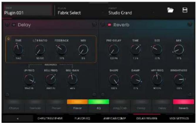
| Parameter | Description | Value | Range |
| Delay Use the button in the upper-left corner to enable or disable delay. | Off, On | ||
| Time Amount of time between the dry signal and the delayed signal. | 1/16 – 16/4 | ||
| L/R | Red Ratio the delay Time in either the Left or Right stereo field. This is useful for creating offset, panned delays. | 50:100 – 100:100 – 100:50 | |
| Feedback | Amount of signal fed back into the delay line. 0–100% | ||
| Mix Wet/dry amount of the delay effect. 0–100% | |||
| Reso LP Freq | Low pass frequency for feedback resonance. 100 – 16000 Hz | ||
| Reso Bell Freq | Center frequency for feedback resonance. | 100 – 16000 Hz | |
| Reso Bell Gain | Amount of gain applied to the resonant frequency. | 0–100% | |
| Reverb | Use the button in the upper-left corner to enable or disable the reverb effect. | Off, On | |
| Pre-Delay | Length of time between dry signal and reverberated signal. | 0 – 250 ms | |
| Time | Length of reverb tail. | 0.3 – 60.00 s | |
| Size | Size of the reverberation environment. | 0–100% | |
| Mix Wet/dry amount of the reverb effect. | 0–100% | ||
| Shape | Shape of the reverberation environment, which will alter the density of reverb reflections. | 0–100% | |
| At lower settings, the sound of individual reflections is more present. | |||
| At higher settings, reflections are more uniform. | |||
| Damp | Amount of frequency dampening applied to the reverberated signal. | 100–0% | |
| HPF Freq | Center frequency for reverb signal high-pass filter. | 0 – 2000 Hz | |
| Brightness | Amount of high frequency decay. | -100–0% | |
MIDI Settings
Use this tab to adjust the MIDI settings for the plugin.

| Parameter | Description | Value | Range |
| Modwheel Destination | Send Mod Wheel data to one of the following control destinations. | Pitch, Cutoff, Reso, Amp, Pan | |
| Depth | Amount of modulation applied.WhenDestinationis set toPitch:-12.0 - +12.0WhenDestinationis set toCutoff, Reso, Amp or Pan:-100 - 0 - 100% | ||
| LFO Ties the modulation to the Control LFO. Off, On | |||
| Aftertouch Destination | Send Aftertouch data to one of the following control destinations. | Pitch, Cutoff, Reso, Amp, Pan | |
| Depth | Amount of modulation applied. 0-100%WhenDestinationis set toPitch:-12.0 - +12.0WhenDestinationis set toCutoff, Reso, Amp or Pan:-100 - 0 - 100% | ||
| LFO Ties the modulation to the Control LFO. Off, On | |||
| Expression | Destination | Send Expression data to one of the following Pitch, Cutoff, Reso, Amp, Pandestinations. | |
| Depth Amount of modulation applied. 0-100%WhenDestinationis set toPitch:-12.0 - +12.0WhenDestinationis set toCutoff, Reso, Amp or Pan:-100 - 0 - 100% | |||
| LFO Ties the modulation to the Control LFO. Off, On | |||
| Footswitch 2 Destination | Send Footswitch 2 data to one of the following control destinations. | Pitch, Cutoff, Reso, Amp, Pan | |
| Depth Amount of modulation applied. 0-100%WhenDestinationis set toPitch:-12.0 - +12.0WhenDestinationis set toCutoff, Reso, Amp or Pan:-100 - 0 - 100% | |||
| LFO Ties the modulation to the Control LFO. Off, On | |||
| Control LFO Shape Waveshape of the Control LFO. Sine, Triangle, | |||
| Sawtooth, Square,S&H Random, S&HALternate, RandomDrift, Slow Drift | |||
| Rate Speed of the low frequency oscillator. | |||
| When Sync is Off: 0.03 – 30.00 HzWhen Sync is On: 8/4 – 1/64 | |||
| Sync Enables or disables Control LFO sync, and sets howthe Control LFO is synced when enabled. | Off, First Note, EachNote, BPM & Note,BPM & Beat | ||
Import Ableton Live Projects
With the MPC Pro Pack, you can now import Ableton Live projects into your MPC.
To import an Ableton Live project:
- On your MPC hardware, press Load or open the Browser from the Menu.
- Navigate to the drive that contains your Ableton Live projects.
- Select an Ableton Live Project (.als file) and then tap Load.
Important: For an Ableton Live project to be successfully imported with all assets, you must use the Collect All and Save option in Ableton Live to collect all of your project resources together.
MPC will attempt to import and convert the following:
- Launch Matrix Tracks/Clips to Tracks/Clips
- Arrangement View Sequence to Arrange tracks.
• ALS Colors to MPC Colors for pads.
• Audio Clips to Audio Clips (with Looping points, names, warp, volume, pan, and pitch adjustment). - MIDI Notes to MIDI Notes at 960 PPQ units, with looping points and names.
- Basic conversion of ALS Drum Rack to XPJ Drum Kit. Only one "Selection" is handled. A maximum of four velocity variations per instrument.
- Basic conversion of ALS Impulse Instrument to XPJ Drum Kit.
- Basic conversion of ALS Sampler to XPJ Keygroup (128 keygroup limit). Only one "Selection" is handled.
- Basic conversion of ALS Simpler to XPJ Keygroup.
- Plugin instrument tracks are converted to MPC MIDI tracks.
AKAI®
PROFESSIONAL
akaipro.com
- Modes 103
- Introduction
- Support
- About This User Guide
- Important Notes
- MPC2 vs. MPC3
- Updates in v3.6
- MPC Pro Pack
- Project Time Signature Support
- Track Edit Enhancements
- MIDI Improvements
- Other Improvements
- Setup
- Tutorial
- Starting Up
- MPC Key 61:
- MPC Key 37:
- Recording Tracks with Main Mode
- Main Mode Overview
- Recording a Drum Sequence
- Trap-Kit-Default Arrangement
- Creating and Recording a Keygroup Track
- Adding and Recording with a Plugin Track
- Working with Audio Tracks
- Recording an External Instrument
- To record audio from an external instrument or microphone:
- Loading Sounds with the Browser
- To add a recorded audio sample to an audio track:
- Working with the Linear Arranger
- Saving Your Work
- Editing Note Events
- Making Basic Sound Edits
- To add an effect:
- Other Features Explained
- Q-Links
- Step Sequencer
- Drum Loops & Chop Mode
- Pad Muting & Track Muting
- Sampling (Recording)
- Sample Editing
- Recording Automation with the XY Pad
- Creating a Song
- SEQUENCE CD BPM BARS
- To export a song:
- Operation
- Important:
- General Features
- Control Types
- Knobs
- Parameter Values
- Drop-Down Menus / Lists
- Selectors
- Buttons
- Checkboxes
- Tabs
- Sliders
- Envelopes
- Tracks
- About Tracks
- To create a new track:
- Audio Tracks
- Settings:
- Drum Tracks
- To load a kit into a drum track:
- To load a sample into a drum track:
- Alternatively, assign samples in a drum track in Track Edit Mode in one of these two ways:
- Keygroup Tracks
- To assign samples in a keygroup track:
- Plugin Tracks
- MIDI Tracks
- CV Tracks
- Menu
- Toolbar
- Sync
- Help
- Undo History
- Tuner
- MIDI Monitor
- Mode
- System Resources
- Project
- Preferences
- Info
- Activations
- Wi-Fi
- Ethernet
- Bluetooth
- Audio Device
- Audio/Export
- MIDI / Sync
- Hardware
- Sequencer
- Project Defaults
- Project Load/Save
- General
- Splice
- To access Splice from this page:
- To browse samples imported from Splice:
- Save Window
- Pull-Down Menu
- Time Counter / Locate
- Timing Correct (TC)
- To open the Timing Correct settings:
- Metronome (Click/Metro)
- Automation
- Global
- To record automation to a track:
- To quickly clear automation from a track:
- Level
- Pad Perform
- Arpeggiator
- To open the Arpeggiator settings:
- Erase
- Effects
- Overview
- Insert Effects
- Pads and Keygroups
- To load a pad or keygroup insert effect in Main Mode:
- To load a pad or keygroup insert effect in the Pad Mixer:
- To load a pad or keygroup insert effect in Track Edit Mode:
- Tracks, Submixes, and Outputs
- To load a track insert effect in Main Mode:
- To load a submix or output insert effect in Main Mode:
- To load a track, submix, or output insert effect in the Channel Mixer:
- To load XYFX for a track, submix, or output in XYFX Mode:
- Send/Return Effects
- To load a send/return effect to a return in Main Mode:
- To load a send/return effect to a return in the Channel Mixer:
- To set the return level:
- To set the send levels for a pad or keygroup in Main Mode:
- To set the send levels for a pad or keygroup in Track Edit Mode:
- To set the send levels for a pad or keygroup in the Pad Mixer:
- Tracks and Submixes
- To set the send levels for a track or submix in Main Mode:
- To set the send levels for a track or submix in the Channel Mixer:
- Audio Mixdown
- Audio Length
- Render Source
- Render Options
- File Formats
- Keyboard Control
- Keyboard Input
- Scale Filter
- Internal Keyboard Routing
- External Keyboard Routing
- Keyboard Settings
- Pedal Settings
- Pitch Bend / Mod Wheel
- Global Pitch Bend Settings
- Touch Strip
- To use the touch strip with MPC Key 61 or MPC Key 37:
- Q-Link
- Pad Level
- Track Level
- TouchFX
- To configure the Touch FX settings from an MPC Key:
- Notes
- Pitch Bend
- Mod Wheel
- Sustain
- Expression
- Crossfader
- Battery Usage
- Modes
- Main Mode
- Shortcuts
- Function Buttons
- Sequence Section
- # (0)
- Track Section
- Buses
- Track Edit
- Arrangement Section
- Mixer Strips
- Trap-Kit-Default Outputs 1/2
- Trap-Kit-Default
- 1
- Browser
- Sample Assign
- Channel Mixer
- Volume
- Pan & Volume
- Sends
- Pad Mixer
- Sounds Mode
- Favorites
- To save a preset as a favorite:
- Setlists
- To create a Setlist:
- XYFX Mode
- Arrange Mode
- Recording Arrangements
- To record into the arrangement timeline:
- To replace a section of the arrangement with a new performance:
- To play the arrangement:
- Editing Arrangements
- OF BARS BEFORE BAR
- Arrangement Track Editor
- Saving and Exporting the Arrangement
- Grid View
- If Event Type is set to Drum Events:
- If Event Type is set to Melodic Events:
- Velocity/Automation Lane
- To show or hide the velocity/automation lane:
- To add automation to a track:
- To enter or delete steps in a sequence:
- Examples:
- Step Automation
- To add a step automation parameter:
- List Edit Mode
- : This is the number of the note event.
- Track Edit Mode
- Tips:
- Samples
- Mods (Modulations)
- Inserts
- LFO
- Utilities
- Mod Matrix
- Global (Advanced and Legacy)
- Samples (Advanced and Legacy)
- Filters (Advanced)
- Envelopes (Advanced)
- LFO (Advanced)
- Utilities/Sensitivity (Advanced)
- KG Stack (Advanced)
- Mod Matrix (Advanced)
- Randomize (Advanced)
- Envelopes (Legacy)
- LFO (Legacy)
- Mods (Legacy)
- Effects (Legacy)
- Anatomy of an Envelope
- Track Mute Mode
- Track Mute
- To mute tracks in this mode:
- Track Group
- To assign tracks to track groups:
- Pad Mute Mode
- Pad Mute
- To mute pads in this mode:
- Pad Group
- To use pad groups:
- Track View
- Sample Edit Mode
- Settings
- Trim Mode
- To use both Trim Mode and Chop Mode to edit a sample slice:
- Assigning Samples
- Processing Slices & Samples
- Chop Mode
- Manual
- Threshold
- Regions
- BPM
- Converting or Assigning Slices
- Processing Slices
- Pad Mode
- Sampler
- To set up the Sampler before recording:
- Sample
- Slice
- Pad Tap
- Pad Hold
- Auto Sampler
- Sample Source Information
- Note Range
- Velocity
- Sampling
- Looping
- Q-Link Edit
- Learning Macro Assignments
- To learn parameters to a Macro control in user assignable modes:
- To copy an existing macro assignment:
- Editing Macro Assignments
- To edit the parameters assigned to a macro:
- XY Pad
- To learn a parameter to the crossfader:
- Next Sequence Mode
- MIDI Learn
- To assign a parameter to a hardware control:
- Live Control Mode
- Akai Network Driver
- Configuring Ableton Live
- Control Bar
- Matrix View
- Mixer View
- Device Control View
- Song Mode
- SEQUENCE
- To insert a step:
- Alternatively, "record" a song using the pads:
- To change a step's sequence:
- To convert the current song to a single sequence:
- Key Ranges Mode
- MIDI Control Mode
- Pads
- Q-Link Knobs
- Pad Color Mode
- Looper
- To get started using the Looper:
- To export the loop to an audio track:
- To export the loop to a pad:
- Hardware Features
- MPC X / MPC X Special Edition
- Navigation & Data Entry Controls
- Pad & Q-Link Controls
- Mode & View Controls
- Transport & Recording Controls
- I/O & Level Controls
- Front Panel
- Rear Panel
- MPC Live
- Top Panel
- MPC Live II
- MPC One / MPC One+
- MPC Key 61
- MPC Key 37
- Appendix
- Glossary
- Envelope
- Filter
- Gate
- MIDI
- MIDI Channel
- MIDI Clock
- Modulation
- Note On & Note Off
- Normalize
- Panning
- Pitch-Bend
- Program Change
- Release
- Resonance
- Effects & Parameters
- Delay/Reverb
- AIR Delay
- AIR Diff Delay
- AIR Multitap Delay
- AIR Non-Lin Reverb
- AIR Reverb
- AIR Spring Reverb
- Delay Analog Sync
- Delay Analog
- Delay HP
- Delay LP
- Delay Mono Sync
- Delay Mono
- Delay Multi-Tap
- Delay Ping Pong
- Delay Stereo
- Delay Sync (Stereo)
- Delay Tape Sync
- Reverb In Gate
- Reverb Large 2
- Reverb Large
- Reverb Medium
- Reverb Out Gate
- Reverb Small
- Sample Delay
- Dynamics
- AIR Channel Strip
- AIR Compressor
- AIR Limiter
- AIR Maximizer
- AIR Noise Gate
- AIR Pumper
- AIR Transient
- Bus Compressor
- Compressor Opto
- Compressor VCA
- Compressor Vintage
- Mother Ducker Input
- Mother Ducker
- Transient Shaper
- EQ/Filter
- AIR Enhancer
- AIR Filter Gate
- AIR Filter
- AIR Kill EQ
- AIR Para EQ
- AIR Vintage Filter
- HP Filter Sweep
- HP Filter Sync
- HP Filter
- HP Shelving Filter
- LP Filter Sweep
- LP Filter Sync
- LP Filter
- LP Shelving Filter
- PEQ 2-Band, 2-Shelf
- PEQ 4-Band
- Harmonic
- AIR Amp Sim
- AIR Diode Clip
- AIR Distortion
- AIR Flavor
- AIR Freq Shift
- AIR Lo-Fi
- AIR Talk Box
- AIR Tube Drive
- Decimator
- Distortion Amp
- Distortion Custom
- Distortion Fuzz
- Distortion Grimey
- Distortion Overdrive
- Frequency Shifter
- Granulator
- Resampler
- Manual Filter
- Beat Sync Filter
- Beat Sync Delay
- Beat Repeat
- Tape Stop
- Phaser
- Comb Filter
- Washout
- Manual Flanger
- XYFX
- AIR Chorus
- AIR Ensemble
- AIR Flanger
- AIR Fuzz Wah
- AIR Half Speed
- AIR Multi-Chorus
- AIR Phaser
- AIR Pitch Shifter
- AIR Stereo Width
- AIR Stutter
- Auto Wah
- Autopan Sync
- Autopan
- Chorus 2-Voice
- Chorus 4-Voice
- Flanger Sync
- Flanger
- Phaser 1
- Phaser 2
- Phaser Sync
- Tremolo Sync
- Tremolo
- Vocal
- AIR Vocal Doubler
- AIR Vocal Harmonizer
- AIR Vocal Tuner
- Plugins
- Bassline
- Osc / Filter / Envelope
- Velocity / Global / Chorus
- Delay
- Compressor / Hype
- Electric
- Pickup / Env
- Bell / Noise
- Trem / Tube / Chorus
- Spring Reverb
- Hype
- Macro
- Filter / Amp
- Effects 1
- Effects 2
- TubeSynth
- Oscillator
- Mixer / Filter
- Chorus
- Reverb / Compressor / Hype
- DrumSynth
- Drum Sound
- Trans/Dist
- EQ/Comp
- DrumSynth 1–8 / Trans/Dist / EQ/Comp
- Send FX
- Mixer / FX / Sends
- Mellotron
- Model
- Flavor / Compressor / EQ
- Delay / Spring Reverb
- Solina
- Ensemble
- Sound
- Flavor
- Chorus / EQ
- WayOutWare Odyssey
- VCO 1/2
- Mod/Env
- Mix/Filter
- SATA Drive Installation
- MIDI Machine Control (MMC)
- To set up your MPC hardware to send MMC messages to an external device:
- To set up your MPC hardware to receive MMC messages from an external device:
- Ableton Control Maps
- Transport Controls
- Right-Hand Side Buttons
- Left-Hand Side Buttons
- Shift Controls
- Basic Controls
- Technical Specifications
- Trademarks & Licenses
- Addenda
- MPC Clip Launching
- Clip Matrix Mode
- Navigate Mode
- Clip Editor Mode
- Main Mode – Arrangement & Clip Section
- Arrangement
- Clips
- To edit clip settings, tap and hold on the clip name and then tap Settings:
- Advanced CV Track Edit
- Routing
- Env 1-4
- LFO 1-4
- Stepper
- Matrix
- Q-Link Edit – Envelope Follower / LFO
- Super Warp Algorithm
- Pro Pack Plugins
- AIR Visual EQ4
- AIR Reverb Pro
- Early Reflections
- Parameter Description Value Range
- Tail
- EQ/Dynamic
- AIR Utility
- Parameter
- Description
- Value
- Range
- AIR Fabric Select
- Main / Perc / Settings
- Perc
- Layer 1/2
- Amp
- Pitch
- Chrs / Trem / Phsr
- Flavor/EQ
- Amp/Cab/Comp
- MIDI Settings
- Import Ableton Live Projects
- To import an Ableton Live project:
Brand : AKAI
Model : MPC Live II
Category : DJ Equipment