
P3R - Microphone SHURE - Free user manual and instructions
Find the device manual for free P3R SHURE in PDF.


| Product Type | Wireless Bodypack Receiver (PSM300 Personal Monitor System) |
| Brand | Shure |
| Model | P3R |
| Frequency Range | 488-937.5 MHz (varies by region) |
| Operating Range | Up to 90 m (300 ft) under typical conditions |
| Audio Frequency Response | 38 Hz – 15 kHz |
| Signal-to-Noise Ratio | 90 dB (A-weighted, typical) |
| Total Harmonic Distortion | < 0.5% (typical) |
| Headphone Output Power | 80 mW per channel @ 32Ω, 1% THD |
| Minimum Load Impedance | 16 Ω |
| Dimensions (H x W x D) | 110 x 64 x 21 mm |
| Weight (without batteries) | 98 g (3.5 oz) |
| Power Source | 2 x AA alkaline batteries |
| Battery Life | 5–7 hours continuous use |
| Display | LCD showing group, channel, MixMode, and battery status |
| Controls | Group, Channel, Scan, Sync, Volume, MixMode knob |
| Audio Output Connector | 3.5 mm (1/8) stereo headphone jack |
| Antenna | Internal or external 1/4 wave (supplied) |
| Operating Modes | Stereo, MixMode (two-channel mono blend), Mono |
| Sync Method | IR sync between receiver and P3T transmitter |
| Scanning | Group scan and channel scan for clean frequencies |
| RF Sensitivity | 2.2 μV at 20 dB SINAD |
| Included Accessories | P3R receiver, earphones (SE112 or SE215), 2 AA batteries, carrying bag |
| Safety Features | Volume limit, hearing protection warnings, power-save mode |
| Cleaning Instructions | Clean with a dry cloth only; keep away from water and extreme temperatures |
Frequently Asked Questions - P3R SHURE
User questions about P3R SHURE
0 question about this device. Answer the ones you know or ask your own.
Ask a new question about this device
Download the instructions for your Microphone in PDF format for free! Find your manual P3R - SHURE and take your electronic device back in hand. On this page are published all the documents necessary for the use of your device. P3R by SHURE.
USER MANUAL P3R SHURE
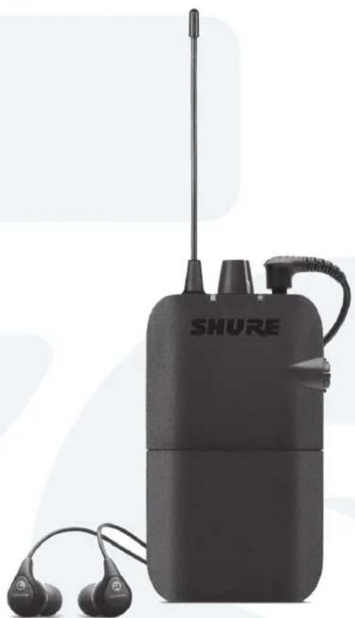
natural_image
Black SHURE airway device with earbuds and antenna, no visible text or symbols on bodyIMPORTANT SAFETY INSTRUCTIONS
-
READ these instructions.
-
KEEP these instructions.
-
HEED all warnings.
-
FOLLOW all instructions.
-
DO NOT use this apparatus near water.
-
CLEAN ONLY with dry cloth.
-
DO NOT block any ventilation openings. Allow sufficient distances for adequate ventilation and install in accordance with the manufacturer's instructions.
-
DO NOT install near any heat sources such as open flames, radiators, heat registers, stoves, or other apparatus (including amplifiers) that produce heat. Do not place any open flame sources on the product.
-
DO NOT defeat the safety purpose of the polarized or groundingtype plug. A polarized plug has two blades with one wider than the other. A grounding type plug has two blades and a third grounding prong. The wider blade or the third prong are provided for your safety. If the provided plug does not fit into your outlet, consult an electrician for replacement of the obsolete outlet.
-
PROTECT the power cord from being walked on or pinched, particularly at plugs, convenience receptacles, and the point where they exit from the apparatus.
-
ONLY USE attachments/accessories specified by the manufacturer.
-
USE only with a cart, stand, tripod, bracket, or table specified by the manufacturer, or sold with the apparatus. When a cart is used, use caution when moving the cart/apparatus combination to avoid injury from tip-over.
-
UNPLUG this apparatus during lightning storms or when unused for long periods of time.
-
REFER all servicing to qualified service personnel. Servicing is required when the apparatus has been damaged in any way, such as power supply cord or plug is damaged, liquid has been spilled or objects have fallen into the apparatus, the apparatus has been exposed to rain or moisture, does not operate normally, or has been dropped.
-
DO NOT expose the apparatus to dripping and splashing. DO NOT put objects filled with liquids, such as vases, on the apparatus.
-
The MAINS plug or an appliance coupler shall remain readily operable.
-
The airborne noise of the Apparatus does not exceed 70dB (A).
-
Apparatus with CLASS I construction shall be connected to a MAINS socket outlet with a protective earthing connection.
-
To reduce the risk of fire or electric shock, do not expose this apparatus to rain or moisture.
-
Do not attempt to modify this product. Doing so could result in personal injury and/or product failure.
-
Operate this product within its specified operating temperature range.
WARNING: This product contains a chemical known to the State of California to cause cancer and birth defects or other reproductive harm.
SAFETY PRECAUTIONS
The possible results of incorrect use are marked by one of the two symbols—"WARNING" and "CAUTION"—depending on the imminence of the danger and the severity of the damage.
| WARNING: Ignoring these warnings may cause severe injury or death as a result of incorrect operation. | |
| CAUTION: Ignoring these cautions may cause moderate injury or property damage as a result of incorrect operation. |
CAUTION
- Never disassemble or modify the device, as failures may result.
- Do not subject to extreme force and do not pull on the cable or failures may result.
- Keep the product dry and avoid exposure to extreme temperatures and humidity.
WARNING
- If water or other foreign objects enter the inside of the device, fire or electric shock may result.
- Do not attempt to modify this product. Doing so could result in personal injury and/or product failure.
This device is able to produce sound volume higher than 85 dB SPL. Please check your maximum allowed continuous noise exposure level based on your national employment protection requirements.
WARNING
LISTENING TO AUDIO AT EXCESSIVE VOLUMES CAN CAUSE PERMANENT HEARING DAMAGE. USE AS LOW A VOLUME AS POSSIBLE. Over exposure to excessive sound levels can damage your ears resulting in permanent noise-induced hearing loss (NIHL). Please use the following guidelines established by the Occupational Safety Health Administration (OSHA) on maximum time exposure to sound pressure levels before hearing damage occurs.
| 90 dB SPLat 8 hours | 95 dB SPLat 4 hours | 100 dB SPLat 2 hours | 105 dB SPLat 1 hour |
| 110 dB SPLat 12 hour | 115 dB SPLat 15 minutes | 120 dB SPLAvoid or damage may occur | |
Important Product Information
LICENSING INFORMATION
Licensing: A ministerial license to operate this equipment may be required in certain areas. Consult your national authority for possible requirements. Changes or modifications not expressly approved by Shure Incorporated could void your authority to operate the equipment. Licensing of Shure wireless microphone equipment is the user's responsibility, and licensability depends on the user's classification and application, and on the selected frequency. Shure strongly urges the user to contact the appropriate telecommunications authority concerning proper licensing, and before choosing and ordering frequencies.
Information to the user
This equipment has been tested and found to comply with the limits for a Class B digital device, pursuant to Part 15 of the FCC Rules. These limits are designed to provide reasonable protection against harmful interference in a residential installation. This equipment generates uses and can radiate radio frequency energy and, if not installed and used in accordance with the instructions, may cause harmful interference to radio communications. However, there is no guarantee that interference will not occur in a particular installation. If this equipment does cause harmful interference to radio or television reception, which can be determined by turning the equipment off and on, the user is encouraged to try to correct the interference by one or more of the following measures:
- Reorient or relocate the receiving antenna.
- Increase the separation between the equipment and the receiver.
- Connect the equipment to an outlet on a circuit different from that to which the receiver is connected.
- Consult the dealer or an experienced radio/TV technician for help.
This device complies with Industry Canada licence-exempt RSS standard(s). Operation of this device is subject to the following two conditions: (1) this device may not cause interference, and (2) this device must accept any interference, including interference that may cause undesired operation of the device.
Industry Canada ICES-003 Compliance Label:
CAN ICES-3 (B)/NMB-3(B)
Note: EMC conformance testing is based on the use of supplied and recommended cable types. The use of other cable types may degrade EMC performance.
Changes or modifications not expressly approved by the manufacturer could void the user's authority to operate the equipment.
PSM®300
The PSM300 Personal Monitor System delivers wireless stereo monitoring for improved clarity and reduced feedback over traditional stage wedges. Performers can create their own custom mixes by adjusting the stereo blend and overall volume level at the bodypack, resulting in lower volume on stage and enhanced audio detail. Easy to set up and operate, PSM300 features one-touch frequency syncing and solid wireless RF stability between transmitters and receivers. With rugged, dependable hardware and hard-working technology, Shure PSM300 Personal Monitor Systems deliver a greatly improved monitoring experience on stage.
Features
- Send two channels of audio wirelessly to performers onstage
• Solid RF connection over a 300 foot (90 meter) range - Create a personal mix on each bodypack with adjustable stereo balance or MixMode® two-channel mono blend.
- Up to 90 dB signal-to-noise ratio provides clear, detailed audio at any volume
- Systems available with Shure Sound Isolating™ earphones
- One-touch scan and IR sync quickly and easily assigns a clean wireless channel
- No complicated menus, just simple volume and mix controls that focus on the performance
• All-metal half-rack transmitter - Slim, lightweight bodypack attaches easily to a belt or guitar strap
Included Components
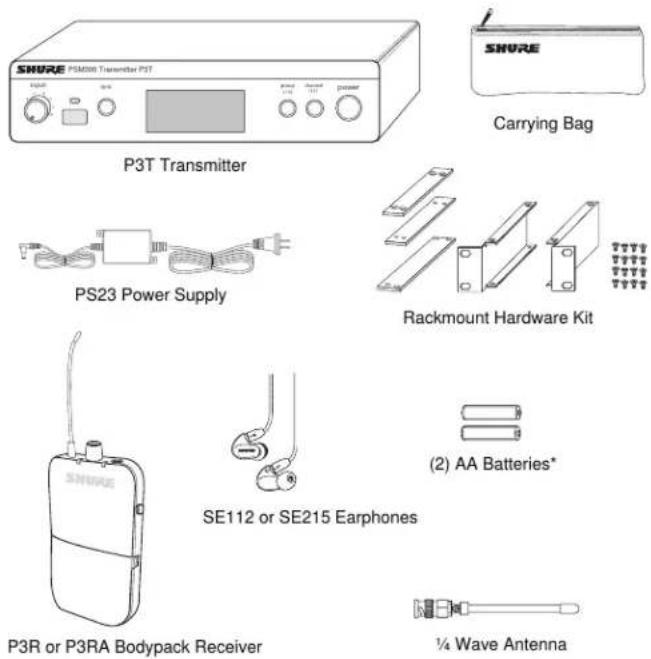
*Not included in Argentina
System Overview
flowchart
graph TD
    A["Personal MixMode settings"] --> B["Stage signals to mixer inputs"]
    C["Mixer Outputs"] --> D["Vocals"]
    D --> E["Drums"]
    E --> F["Instrument"]
    G["P3T"] --> H["Instrument mix (channel 1)"]
    H --> I["Vocal mix (channel 2)"]
    I --> J["Stage signals to mixer inputs"]
    K["Instrument"] --> L["Ch 1"] & M["Ch 2"] & N["Ch 1"] & O["Ch 2"] & P["Ch 1"] & Q["Ch 2"] & R["Ch 1"] & S["Ch 2"] & T["Ch 1"] & U["Ch 2"] & V["Ch 1"] & W["Ch 2"] & X["Ch 1"] & Y["Ch 2"] & Z["Ch 1"] & AA["Ch 2"] & AB["Ch 1"] & AC["Ch 2"] & AD["Ch 1"] & AE["Ch 2"] & AF["Ch 1"] & AG["Ch 2"] & AH["Ch 1"] & AI["Ch 2"] & AJ["Ch 1"] & AK["Ch 2"] & AL["Ch 1"] & AM["Ch 2"] & AN["Ch 1"] & AO["Ch 2"] & AP["Ch 1"] & AQ["Ch 2"] & AR["Ch 1"] & AS["Ch 2"] & AT["Ch 1"] & AU["Ch 2"] & AV["Ch 1"] & AW["Ch 2"] & AX["Ch 1"] & AY["Ch 2"] & AZ["Ch 1"] & BA["Ch 2"] & BB["Ch 1"] & BC["Ch 2"] & BD["Ch 1"] & BE["Ch 2"] & BF["Ch 1"] & BG["Ch 2"] & BH["Ch 1"] & BI["Ch 2"] & BJ["Ch 1"] & BK["Ch 2"] & BL["Ch 1"] & BM["Ch 2"] & BN["Ch 1"] & BO["Ch 2"] & BP["Ch 1"] & BPA["Ch 2"] & BPB["Ch 1"] & BPC["Ch 2"] & BPD["Ch 1"] & BPD["Accumulus Signal"]
    style A fill:#f9f,stroke:#333
    style K fill:#f9f,stroke:#333
    style B fill:#ccf,stroke:#333
    style D fill:#ccf,stroke:#333
    style E fill:#ccf,stroke:#333
    style F fill:#ccf,stroke:#333
    style G fill:#ccf,stroke:#333
    style H fill:#ccf,stroke:#333
    style I fill:#ccf,stroke:#333
    style J fill:#ccf,stroke:#333
    style K fill:#ccf,stroke:#333
    style L fill:#ccf,stroke:#333
    style M fill:#ccf,stroke:#333
    style N fill:#ccf,stroke:#333
    style O fill:#ccf,stroke:#333
    style P fill:#ccf,stroke:#333
    style Q fill:#ccf,stroke:#333
    style R fill:#ccf,stroke:#333
    style S fill:#ccf,stroke:#333
    style T fill:#ccf,stroke:#333
    style U fill:#ccf,stroke:#333
    style V fill:#ccf,stroke:#333
    style W fill:#ccf,stroke:#333
    style X fill:#ccf,stroke:#333
    style Y fill:#ccf,stroke:#333
    style Z fill:#ccf,stroke:#333
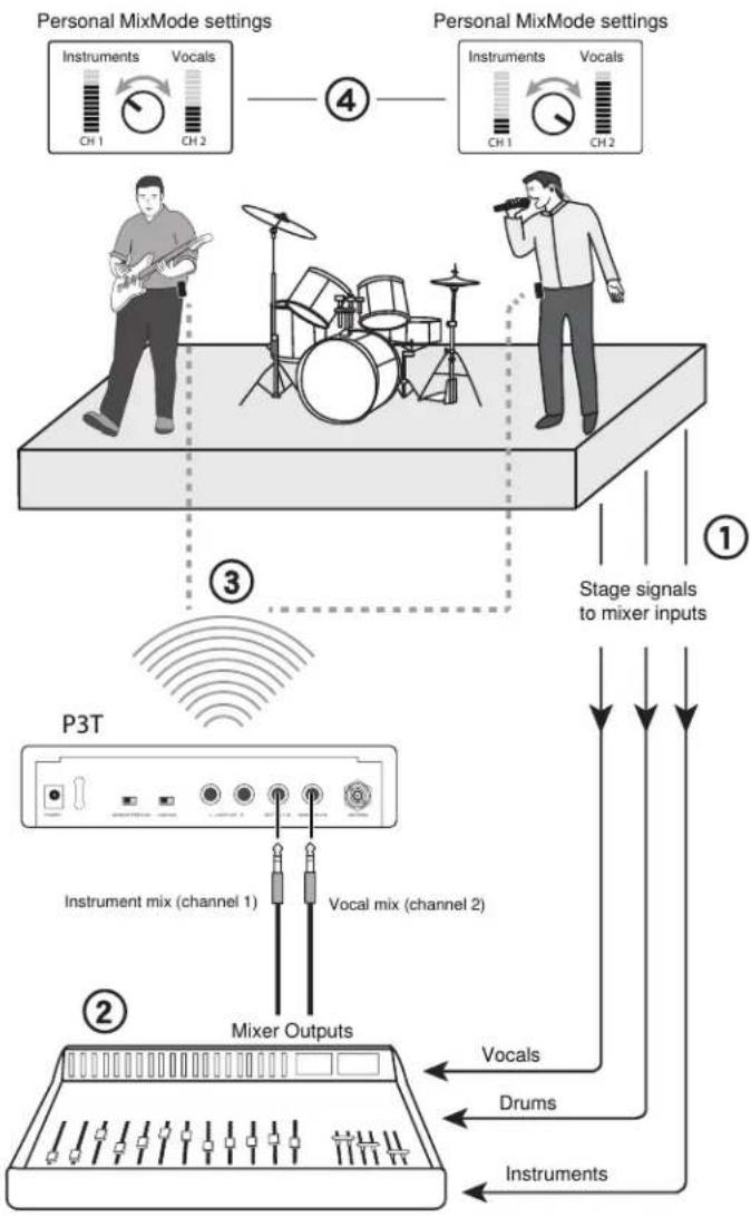
This example shows a typical setup for musical performance. See the System Applications section for additional examples.
① Route audio signals
Send Instrument and microphone signals from the stage to a mixer or PA system.
② Create monitor mixes
From the mixer, create two mixes: one of just the instruments, and a second with just the vocals. Route each of these to separate mixer outputs and connect them to the P3T inputs.
③ Send wireless audio to the performers
Sync the bodypacks to the P3T transmitter to send the mixes to the performers for in-ear monitoring.
④ Adjust personal mixes
Each performer uses the MixMode knob on the bodypack to control their own mix between the instruments and vocals.
P3T Transmitter Front and Rear Panels
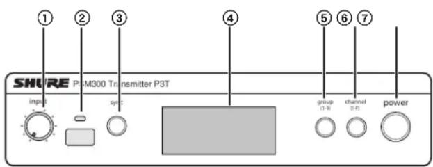
P3T Front Panel
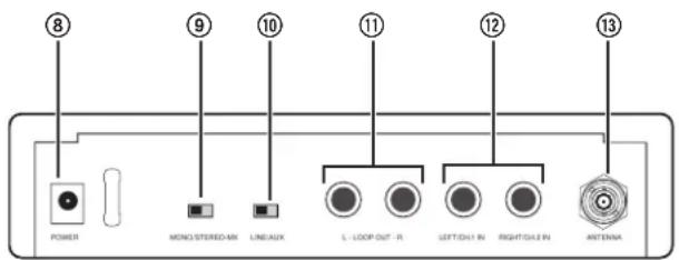
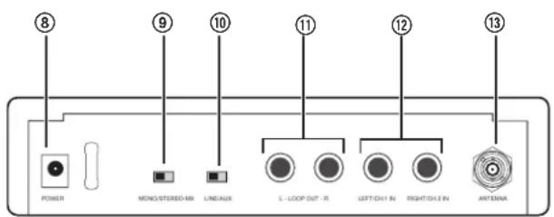
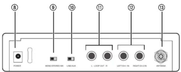
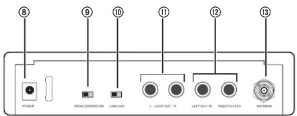
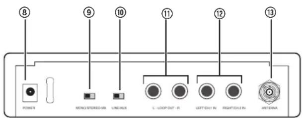
P3T Rear Panel
① Input Level Control
Adjusts the level of the incoming audio signal
② IR Sync Window
Sends and receives group/channel data to sync receivers with the transmitter
③ Sync Button
Press to synchronize the transmitter and receiver to the same group and channel
Note: Sync data is sent through the IR sync window
④ LCD Display
Displays audio, RF, and system information
⑤ Group Button
Press to scroll through group settings
⑥ Channel Button
Press to scroll through channel settings
⑦ Power
Turns power on or off
⑧ Power Input
Connect the supplied Shure PS23 external power supply
⑨ Mono/Stereo-MX Switch
| StereoMX | Sends a two-channel stereo mix to the receiver |
| Mono | Sends a summed audio mix to both receiver channels |
⑩ Line/Aux Switch
Adjust the input sensitivity using the following as a connection reference:
| Aux (-10 dBV): | Consumer audio devices, such as computers or portable media players |
| Line (+4 dBu): | Mixers or other professional audio devices |
⑪ Loop Outputs ( 14 Inch TRS, Balanced)
Connect outputs to additional PSM systems or other audio devices
⑫ Audio Inputs ( 14 Inch TRS, Balanced)
Connect to mixer outputs or other audio sources for monitoring by the performers
⑬ BNC Antenna Connector
Connect the supplied 14 wave antenna, directional antenna, or a Shure P3AC antenna combiner
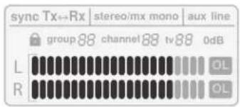
P3T Transmitter Display
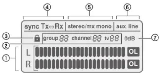
① Audio Input Meter
Indicates the audio signal level
② Group / Channel / TV Setting
Displays selected group and channel settings and the corresponding television channel
Note: the TV indicator only applies to U.S.A. channels, and remains blank in other regions
③ Lock Status
To lock or unlock the controls, press and hold the group and channel buttons until the lock icon appears/disappears.
④ Sync Status
Appears after a successful sync between the transmitter and receiver. The direction of the sync is shown as Tx>Rx (transmitter sends frequency to receiver) or Tx<Rx (receiver sends frequency to transmitter).
⑤ Stereo-MX / Mono Mix
Indicates whether the audio sent to the receiver is a single or two-channel mix (corresponds to the Stereo-MX/Mono switch on the rear panel).
⑥ Aux / Line Mode
Indicates the input sensitivity setting (corresponds to the Aux/Line switch on the rear panel)
⑦ 0 dB Indicator
Turns on when input signal reaches 0 dB. Refer to the section on adjusting gain and listening volume for information on how to use this icon.
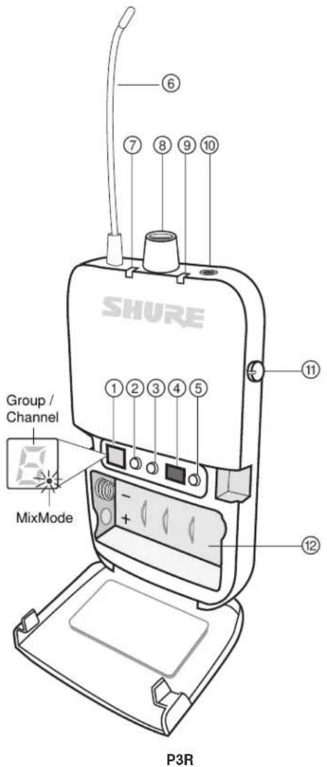
P3RA Receiver
For more demanding applications, Shure offers the P3RA receiver, which features all-metal construction and advanced menu navigation in addition to the features included on the P3R receiver. For more information, please visit www.shure.com.
① Display
Shows group, channel, and MixMode settings
② Group Button
- Press to display group
- Press and hold to edit the group, then press to scroll when display flashes
③ Channel Button
- Press to display channel
- Press and hold to edit the channel, then press to scroll when display flashes
④ IR Sync Window
Sends and receives sync data between the receiver and transmitter
⑤ Scan Button
- Press and hold to perform a group scan
- Press to perform a channel scan
Note: A channel scan selects the best channel in the current group. A group scan finds the group with the most open channels and selects the first available channel in that group.
⑥ Antenna
⑦ Power LED Indicator
Indicates when receiver is on, remaining battery life, and when power-save mode is active. See battery life table for more information.
⑧ Power Switch / Volume Control Knob
Turns the receiver on/off and adjusts master headphone volume level
⑨ RF LED Indicator (blue)
Illuminates when tuned to an active transmitter group and channel
⑩ Headphone Output
Connects to earphones or headphones
⑪ MixMode Control Knob
- When operating in MixMode, this knob blends channels 1 and 2 into a single mix
- When operating in stereo mode, this knob adjusts the left/right balance
⑫ Battery Compartment
Holds 2 x AA batteries
Battery Life
| LED Behavior Remaining Runtime (Hours) | |
| Green 5-7 | |
| Amber 1-3 | |
| Red (solid) 0.5-1 | |
| Red (flashing) 0 | |
Battery life was measured using Energizer™ alkaline batteries, under the following conditions:
• Transmitter sensitivity: Line (+4dBu)
• Audio output from receiver: 100 dB through Shure SE112 earphones
Power-save mode: When there are no earphones plugged in, the receiver enters power-save mode to preserve battery life. The LED slowly fades on/off in this mode and continues to display the color that represents the remaining battery life.

Applications
Refer to the following PSM300 system scenarios prior to installation. Understanding the configuration options before setting up helps to identify signal routing requirements and plan for future expansion. Specific information on how to set up the PSM300 system and create mixes for monitoring can be found in the "System Setup and Configuration" and "Operation" sections of this user guide.
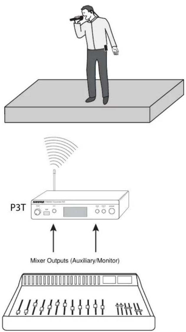
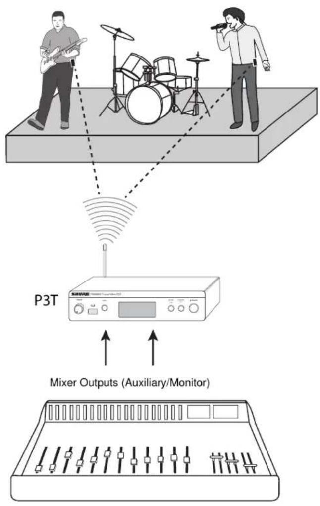
Single System for an Individual Performer
This configuration provides in-ear monitoring in a solo performance, or in a group performance in which only one person requires wireless monitoring. This system can be expanded for multiple performers by using additional P3R bodypack receivers tuned to the same transmitter.
Single Transmitter with Multiple Receivers
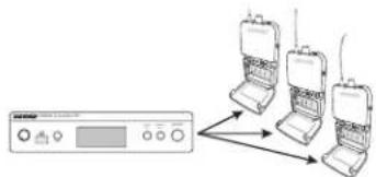
Multiple performers can monitor audio from the same transmitter and still adjust the signal at their bodypack to personalize the mix. Simply tune each bodypack to the same frequency as the transmitter and use the MixMode knob to adjust the mix.
MixMode or Stereo Operation:
Each performer has the option of setting their bodypack to MixMode or Stereo when the transmitter is set to Stereo-MX. When the bodypack is powered on, it is set to stereo by default. To operate in MixMode, hold the GROUP button when turning the power on. For information on these modes, see "MixMode and Stereo Monitoring".
Multiple Transmitters with Separate Mixes
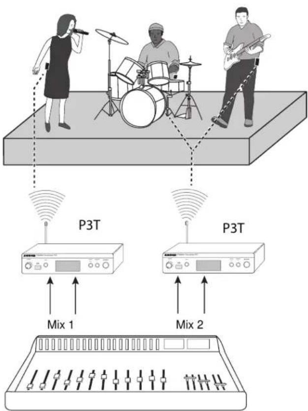
When several performers in a group have different monitoring requirements, multiple PSM300 systems may be used simultaneously to send different mixes through each transmitter. This setup requires a mixer with two monitor/auxiliary outputs for each transmitter.
Tip: To simplify setup in applications that involve multiple transmitters, Shure offers the P3AC antenna and power distribution system, which supplies up to four PSM transmitters with power and RF from a single source.
Signal Routing to External Devices (Combination Systems)
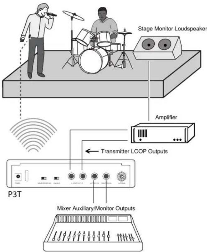
The LOOP outputs pass audio to an external device, such as other personal monitoring systems, recording devices, or stage monitors. The signal at the LOOP outputs is identical to the signal coming from the mixer, and is not affected by the transmitter volume or input sensitivity (line/aux) settings. This makes the LOOP outputs particularly useful when using a mixer that has one or two monitor/auxiliary sends.
Using the PSM300 simultaneously with Loudspeakers:
A combination monitoring system can be used, where some of the performers are using the PSM300 wireless system and others are listening through loudspeakers on stage.
Note: If using passive stage monitors, the P3T outputs must be connected to an amplifier. Active (amplified) speakers can be connected directly to the P3T outputs.
Using the PSM300 Combined with Other Wireless Monitoring Systems
In a scenario where two performers have their own wireless monitoring systems (one Shure PSM300 system and one third-party system, for example), the PSM300 can pass the signal from the mixer on to the second monitoring system.
System Setup and Configuration
Rack Mounting
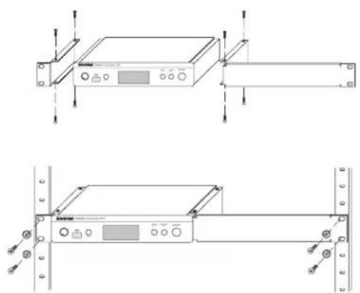
The P3T Transmitter can be mounted in a standard 19-inch rack. Up to two units can be mounted in a single rack space. If using multiple P3T transmitters, the Shure PA411 Antenna Combiner system can be used to consolidate and distribute all RF and power for up to four transmitters.
Single unit
Dual-mounting two units
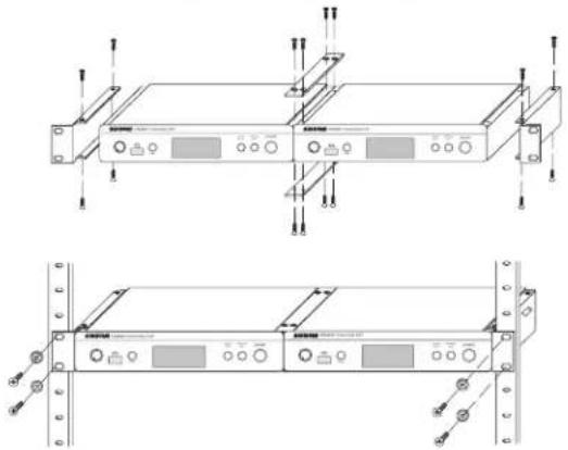
Note: Always use both straddle bars when mounting two units.
Power, Audio, and RF Connections
- Use the power adapter to connect the P3T to an AC power source.
- Install 2 AA batteries in the bodypack receiver.
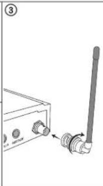
- Attach the antenna to the BNC antenna connector on the P3T rear panel.
- Connect the mixer or audio source to the P3T audio inputs using 14 inch balanced cables.
Important: When connecting to only one transmitter input, use the LEFT/CH1 input. Set the transmitter to MONO to hear audio on both channels of the receiver.
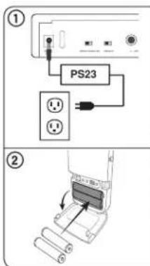
natural_image
Diagram of a wireless signal device with antenna and connector (no text or symbols)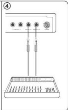
natural_image
Diagram of a device with four ports and two connectors, no text or symbols presentScanning for the Best Open Channel
Follow these steps to scan the RF environment and find the best available frequency for operation:
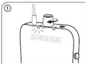
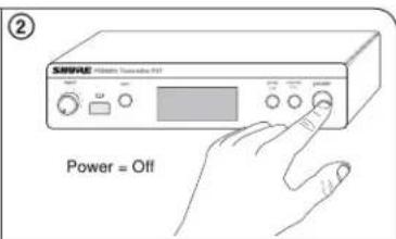
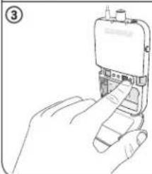
- Turn on the bodypack receiver and any potential sources of interference, including wireless systems, computers, audio equipment, cellular phones, LED panels, and other electronic devices that will be in use during a performance.
- Make sure the P3T transmitter is OFF.
- Position the receiver in the performance area and press SCAN to survey the available channels within the current group setting.
If using several PSM300 systems or operating in a location with a high volume of wireless devices, perform a group scan first, followed by a channel scan:
Group Scan: Press and hold the SCAN button on the receiver.
Channel Scan: Press the SCAN button on the receiver.
natural_image
Line drawing of a hand inserting a device into a mobile phone (no text or symbols visible)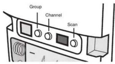
Creating a Wireless Connection Between Receivers and Transmitters (Sync)
To pass audio from the transmitter to the receiver, both must be tuned to the same frequency. The easiest way to configure the system is to use the automatic sync feature. This transfers group and channel settings with a press of a button. Based on your system configuration, use one of the following processes to sync the components:
Single Transmitter and Receiver
The following sync procedure should be used with a setup that consists of a single transmitter and receiver, unless a group/channel setting has been assigned prior to a performance.
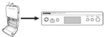
Sync from receiver to transmitter:
- Perform a scan on the receiver (see "Scanning for the Best Open Channel" for best practices).
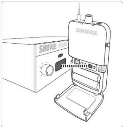
- Align the IR windows on the receiver and transmitter. The windows should be 6-11 cm apart.
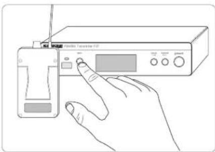
- Press the SYNC button on the transmitter while the blue RF LED on the receiver is flashing.
- The Transmitter displays SYNC when the sync is successful. The arrow between Rx (receiver) and Tx (transmitter) shows the direction of the sync.
Note: When the RF LED on the receiver is flashing after performing a scan, the receiver sends its frequency setting to the transmitter. After it stops flashing, pressing SYNC sends the frequency setting from the transmitter to the receiver.
natural_image
Line drawing of a SHURE PSM001 device with control panel and base tray (no text or symbols on device body)Align the IR windows to sync the receiver and transmitter
Single Transmitter and Multiple Receivers
The following sync procedure should be used with a setup that consists of a single transmitter with multiple receivers, or if a specific group/channel setting has been assigned to the transmitter prior to a performance.
flowchart
graph TD
    A["Device 1"] --> B["Signal Line"]
    C["Device 2"] --> B
    D["Device 3"] --> B
    B --> E["Output Line"]
Sync from transmitter to receivers:
- Sync the first receiver to the transmitter using the sync procedure for a single receiver. Performing a scan and using the resulting group and channel from the receiver is recommended.
- Set additional receivers to the transmitter frequency (one at a time) using IR sync:
- Align the IR windows on the receiver and transmitter and press SYNC.
• The receiver LED should not be flashing when pressing SYNC.
Note: Receivers can also be manually tuned to the transmitter if an IR sync is not practical.
natural_image
Line drawing of a hand operating a portable electronic device with control panel (no text or symbols visible)Pressing the SYNC button transfers group/channel data
Multiple Transmitters and Multiple Receivers
- Set up the first transmitter and all associated receivers according to the appropriate sync procedure. Keep the transmitter and all receivers from this first system powered on when setting up additional systems.
- Set up each additional system using the appropriate sync process. Always leave each new system on before setting up an additional one.
Manual Selection
If frequencies have been planned ahead of time, the group and channel can be set manually without performing a scan. Refer to the frequency table at the end of this user guide to identify frequencies for each group/channel setting.
To select group/channel settings on the receiver and transmitter:
- Press GROUP to scroll through group settings.
- Press CHANNEL to scroll through channel settings within the selected group.
Adjusting Gain and Listening Volume
For the best audio quality, start by adjusting the levels from the mixer or audio source, and then adjust levels through the PSM300 system. This approach corresponds to the way that the audio signal flows through the system, and maximizes the signal-to-noise ratio.
Before you begin: verify all signal routing and gain settings at the mixer or source prior to adjusting any levels from the PSM300 system. If the sound is distorted or faint when it enters the P3T transmitter, there is likely an issue elsewhere in the signal chain that needs to be resolved.
① Adjust Transmitter Levels:
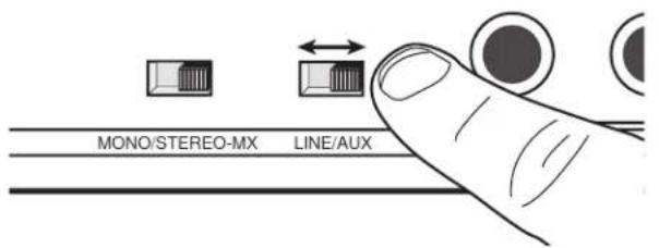
Input Sensitivity
Select the setting that matches the input source:
| Line (+4 dBu) | Use with mixers or other professional audio devices that send line-level signals. |
| Aux (-10 dBV) | Use when connecting consumer audio devices such as portable audio players or computers. |
Note: When using consumer audio devices, the output volume of the device should typically be adjusted as close to the maximum setting as possible without distorting or clipping at the output of the device. This maximizes the signal-to-noise ratio.
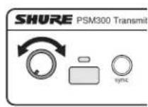
Input Level
Adjust the level so that average levels on the audio meter reach approximately 75% of the full range. The highest levels should occasionally hit the 0dB indicator on the audio input meter, without reaching the OL (overload) indicator.
Tip: If a sound check before the performance is possible, everyone should play at the loudest anticipated volume so that attenuation is not required during the performance.
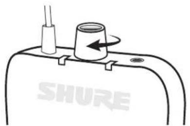
② Adjust Receiver Volume:
After levels are established at the mixer and transmitter, use the headphone volume control on the bodypack receiver to adjust overall listening volume. For information on adjusting the left/right balance or customizing the mix blend, see "MixMode and Stereo Monitoring".
natural_image
Simple line drawing of a mechanical component with a cylindrical part and a pin, labeled 'SHURE' at the base (no text or symbols on the component itself)Creating Monitor Mixes
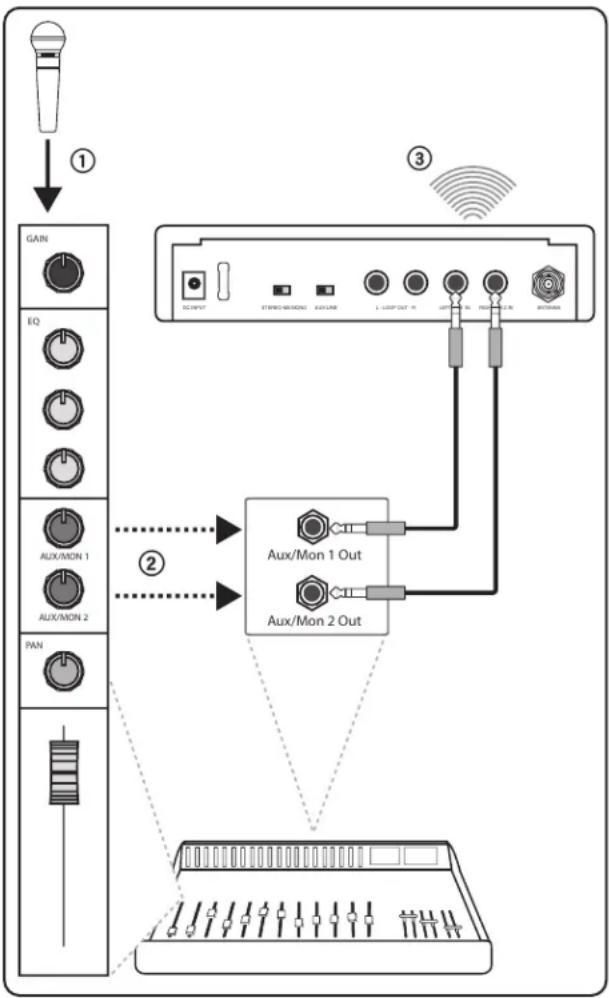
The mix that performers hear on stage is usually different than the mix heard by the audience. In live sound applications, the engineer creates a separate mix to send to the performer by routing the input signals to specified mixer outputs, usually called Monitor or Auxiliary outputs.
The following scenario demonstrates a generic signal path for monitoring mixes, and may not reflect the routing for all mixer types. Consult the user guide for your mixer for detailed signal routing options.
① Mixer Channel
Each mixer channel controls audio processing and routing for a single audio source. In this example, a vocal microphone is plugged into the mixer channel.
② Monitor/Auxiliary Sends
Adjust the signal levels to send to the monitor/auxiliary outputs, each of which corresponds to a separate monitoring mix. Each of these mixes are sent to separate channels on the P3T transmitter.
Note: The channel faders on most mixers do not affect the volume of the monitor/auxiliary sends.
③ Wireless Transmission
Each monitoring mix is transmitted on a separate channel to the P3R receiver. The MixMode knob on the bodypack adjusts the blend between the audio from channel 1 and channel 2.
flowchart
graph TD
    A["Input"] --> B["Gain"]
    B --> C["EQ"]
    C --> D["AUX/MON 1"]
    C --> E["AUX/MON 2"]
    C --> F["PAN"]
    B --> G["Output"]
    G --> H["Aux/Mon 1 Out"]
    G --> I["Aux/Mon 2 Out"]
    H --> J["Switch"]
    I --> K["Switch"]
    J --> L["AC INPUT"]
    K --> M["AC INPUT"]
    L --> N["STORM REMOND"]
    M --> O["STORM REMOND"]
    N --> P["AUX LINE"]
    O --> Q["AUX LINE"]
    P --> R["L LOOP OUT / IN"]
    Q --> S["L LOOP OUT / IN"]
    R --> T["LED/USB"]
    S --> U["LED/USB"]
    T --> V["PROFESSIONAL"]
    U --> W["PROFESSIONAL"]
MixMode and Stereo Monitoring
The receiver can operate in stereo or MixMode when the transmitter is set to STEREO-MX. In applications that involve multiple bodypack receivers tuned to a single transmitter, some bodypacks can operate in stereo, while others operate in MixMode.
Selecting the Mode
Stereo: The receiver is set to stereo mode by default. To switch from MixMode to stereo, simply turn the receiver off and it will return to stereo mode when powered back on.
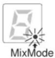
MixMode: Press and hold the GROUP button on the bodypack receiver while turning the power on. The MixMode indicator light on the receiver display turns on to confirm the setting. The receiver will return to stereo mode after it has been powered off.
Stereo
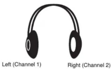
Audio from channel 1 is heard on the left earphone, while audio from channel 2 is heard on the right earphone. Listening in stereo mode increases separation between the sources on each channel, which can improve clarity when many sources are being monitored. The MixMode knob on the bodypack adjusts left/right balance when operating in stereo mode.
MixMode
MixMode allows performers to adjust the blend between two monitoring mixes (an instrumental mix and a vocal mix, for example). When using MixMode:
• Each mix is heard through both the left and right earphones
- The MixMode knob adjusts the volume blend between the two monitor mixes (channel 1 and channel 2)
• Each bodypack receiver can dial in a unique blend to meet the monitoring needs of each performer
Adjusting mix levels
In this scenario, an instrumental mix is on channel 1 and a vocal mix is on channel 2:
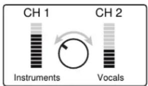
To hear more of channel one, turn the MixMode knob to the left.
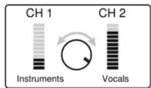
To hear more of channel two, turn the MixMode knob to the right.
When to Use the Mono Setting
In some cases, only a single input on the transmitter is used (if the mixer only features a single monitor/auxiliary output, for example). To ensure that audio is heard on both the left and right earphones:
- Use the LEFT/CH1 input on the transmitter
- Set the transmitter to MONO
Note: When the transmitter is set to mono operation, the MixMode knob will not affect the sound.
Troubleshooting
| Problem Solution | |
| Distorted Audio | Check the volume levels at the P3T transmitter and verify that the meter is not reaching the overload indicatorCheck levels going in and out of the mixer. If audio is distorting anywhere in the signal chain, it will be distorted even if the PSM300 system is not overloading.Make sure batteries in the receiver are freshVerify that the cables are 1/4 inch balanced. If an unbalanced instrument or speaker cable is used, it may introduce noise.Tip:To tell the difference, look at the connectors on the cable. The metal connector on a balanced cable has two plastic rings that divide it into three separate sections (tip, ring, sleeve). An unbalanced cable only has a single plastic ring that divides the metal portion into two sections (tip, sleeve).Check that all cables are plugged all the way into the mixer and the P3T inputs. Sometimes, if a cable is not fully inserted, the signal will be faint and distorted.Make sure you are using the line-level outputs from the mixer. If you have a powered mixer, do not use the main speaker outputs, as they are amplified signals and will overload the P3T inputs. |
| No sound from receiver | Make sure the transmitter and receiver are linked to the same group and channelVerify levels are registering at the transmitter and that the volume is turned up on the receiverCheck that the receiver is on and that the headphones are properly connected to the receiver |
| Turning the MixMode knob does not affect the sound | The Stereo-MX/Mono switch on the rear panel of the P3T may be switched to mono. For the MixMode knob to work, the transmitter must be set to Stereo-MX.Verify that the signals going from the mixer to the transmitter are not identicalCheck that the bodypack is set to MixMode |
| Low audio output at the receiver | Check headphone connection and volume levelIf only sending a single channel into the P3T transmitter, check it the MixMode knob isn't turned towards a silent channel. If using one channel, set the P3T transmitter to mono mode. |
| Audio or RF drops out | Perform a scan to ensure the receiver is on a clear (available) frequencyMake sure there is a line-of-sight path between the transmitter antenna and the bodypack receiversVerify that other wireless devices that are being monitored, such as wireless microphones, are not experiencing RF dropoutsIf using an antenna other than the one included with the system, make sure it is designed to operate in the correct frequency range |
| IR sync failure Verify distance between receiver and transmitter is between 6-11 cm | |
Optional Accessories and Replacement Parts
| Bodypack receiver P3R | |
| Half-rack Transmitter P3T | |
| Universal bodypack receiver P3RA | |
| Antenna and power distribution system PA411 | |
| Wired PSM bodypack P9HW | |
| Dynamic MicroDriver earphones SE112 | |
| Dynamic MicroDriver earphones SE215 | |
| High-definition MicroDriver earphones with tuned bass port SE315 | |
| High-definition earphones with dual MicroDrivers SE425 | |
| High-definition earphones with triple MicroDrivers SE535 | |
| High-definition earphones with quad MicroDrivers SE846 | |
| Carrying/Storage Bag 95A2313 | |
| 1/4 wave antenna (774-952 MHz) | UA400 |
| 1/4 wave antenna (470-752 MHz) | UA400B |
Specifications
PSM300
RF Carrier Range
488-937.5 MHz
varies by region
Compatible Frequencies
Per band
up to 15
Tuning Bandwidth
24 MHz Maximum
Note: varies by region
Operating Range
environment dependent
90 m (300 ft)
Audio Frequency Response
38 Hz–15 kHz
Signal-To-Noise Ratio
A-Weighted
90 dB (typical)
Total Harmonic Distortion
ref. ±34 kHz deviation @1 kHz
<0.5% (typical)
Companding
Patented Shure Audio Reference Companding
Spurious Rejection
ref. 12dB SINAD
80 dB (typical)
Frequency Stability
±2.5 ppm
MPX Pilot Tone
19 kHz (±1 Hz)
Modulation
FM*, MPX Stereo
*ref. ±34 kHz deviation @1 kHz
Operating Temperature
-18°C to +63°C
P3R
Active RF Sensitivity
at 20 dB SINAD
2.2 μV
Image Rejection
90 dB
Adjacent Channel Rejection
60 dB
Intermodulation Attenuation
50 dB
Blocking
60 dB
Audio Output Power
1kHz @ <1% distortion, peak power, @32Ω
80 mW (per output)
Minimum Load Impedance
16 Ω
Headphone Output
3.5 mm (1/8") stereo
Net Weight
98 g(3.5 oz.) (without batteries)
Dimensions
110 x 64 x 21 mm H x W x D
Battery Life
5–7 hours (continuous use) AA batteries
P3T
RF Output Power
10, 20, 30 mW
Note: varies by region
RF Output Impedance
50 Ω (typical)
Net Weight
783 g(27.6 oz.)
Dimensions
43 x 198 x 172 mm (1.7 x 7.8 x 6.8 in.), H x W x D
Power Requirement
12-15V DC, 260 mA Maximum
Audio Input
Connector Type
6.35 mm (1/4") TRS
Polarity
Tip positive with respect to ring
Configuration
Electronically balanced
Impedance
40 kΩ (actual)
Nominal Input Level
switchable: +4 dBu, -10 dBV
Maximum Input Level
| +4 dBu | +22 dBu |
| -10 dBV | +12.2 dBu |
Pin Assignments
Tip=hot, Ring=cold, Sleeve=ground
Phantom Power Protection
Up to 60 V DC
Audio Output
Connector Type
6.35 mm (1/4") TRS
Configuration
Electronically balanced
Impedance
Connected directly to inputs
Certifications
This product meets the Essential Requirements of all relevant European directives and is eligible for CE marking.
Meets essential requirements of the following European Directives:
• Low Voltage Directive 2006/95/EC
• R&TTE Directive 99/5/EC
• WEEE Directive 2002/96/EC, as amended by 2008/34/EC
• RoHS Directive 2002/95/EC, as amended by 2008/35/EC
Note: Please follow your regional recycling scheme for batteries and electronic waste
Conforms to the relevant requirements of regulation (EC) No.278/2009, for low voltage external power supplies.
Meets requirements of the following standards: EN 300 422 Parts 1 and 2, EN 301 489 Parts 1 and 9
The CE Declaration of Conformity can be obtained from: www.shure.com/europe/compliance
Authorized European representative:
Shure Europe GmbH
Headquarters Europe, Middle East & Africa
Department: EMEA Approval
Jakob-Dieffenbacher-Str. 12
75031 Eppingen, Germany
Phone: 49-7262-92 49 0
Fax: 49-7262-92 49 11 4
Email: EMEAsupport@shure.de
P3T
Certified under FCC Part 74.
Certified by IC in Canada under RSS-123 and RSS-102.
IC: 616A-P3TA, 616A-P3TB, 616A-P3TD.
Approved under the Declaration of Conformity (DoC) provision of FCC Part 15.
Complies with requirements set out in RSS-GEN.
This device complies with Industry Canada licence-exempt RSS standard(s). Operation of this device is subject to the following two conditions: (1) this device may not cause interference, and (2) this device must accept any interference, including interference that may cause undesired operation of the device.
Licensing: A ministerial license to operate this equipment may be required in certain areas. Consult your national authority for possible requirements. Changes or modifications not expressly approved by Shure Incorporated could void your authority to operate the equipment. Licensing of Shure wireless microphone equipment is the user's responsibility, and licensability depends on the user's classification and application, and on the selected frequency. Shure strongly urges the user to contact the appropriate telecommunications authority concerning proper licensing, and before choosing and ordering frequencies.
Information to the user
This equipment has been tested and found to comply with the limits for a Class B digital device, pursuant to Part 15 of the FCC Rules. These limits are designed to provide reasonable protection against harmful interference in a residential installation. This equipment generates uses and can radiate radio frequency energy and, if not installed and used in accordance with the instructions, may cause harmful interference to radio communications. However, there is no guarantee that interference will not occur in a particular installation. If this equipment does cause harmful interference to radio or television reception, which can be determined by turning the equipment off and on, the user is encouraged to try to correct the interference by one or more of the following measures:
- Reorient or relocate the receiving antenna.
- Increase the separation between the equipment and the receiver.
- Connect the equipment to an outlet on a circuit different from that to which the receiver is connected.
- Consult the dealer or an experienced radio/TV technician for help.
Australia Warning for Wireless
This device operates under an ACMA class licence and must comply with all the conditions of that licence including operating frequencies. Before 31 December 2014, this device will comply if it is operated in the 520-820 MHz frequency band. WARNING: After 31 December 2014, in order to comply, this device must not be operated in the 694-820 MHz band.
Note: EMC conformance testing is based on the use of supplied and recommended cable types. The use of other cable types may degrade EMC performance.
Please follow your regional recycling scheme for batteries, packaging, and electronic waste.
Frequency Range and Transmitter Output Power
| BAND RANGE (MHz) Output Power (mW) | ||
| G20 488 - 512 30 | ||
| H8E 518 - 542 10 | ||
| J10 584 - 608 30 | ||
| J13 566 - 590 30 | ||
| JB 806 - 810 10 | ||
| K12 614 - 638 30 | ||
| K3E 606 - 630 30 | ||
| L18 630 - 654 10 | ||
| L19 630 - 654 30 | ||
| M16 686 - 710 30 | ||
| M18 686 - 710 10 | ||
| Q25 742 - 766 30 | ||
| R12 794 - 806 10 | ||
| S8 823 - 832 20 | ||
| T11 863 - 865 10 | ||
| X7 925 - 937.5 10 |
NOTE: This Radio equipment is intended for use in musical professional entertainment and similar applications. This Radio apparatus may be capable of operating on some frequencies not authorized in your region. Please contact your national authority to obtain information on authorized frequencies and RF power levels for wireless microphone products.
CONSIGNES DE SÉCURITÉ IMPORTANTES
*Non comprises en Argentine
natural_image
Technical line drawings of a rack-mounted electronic device with mounting brackets and control panel (no text or symbols)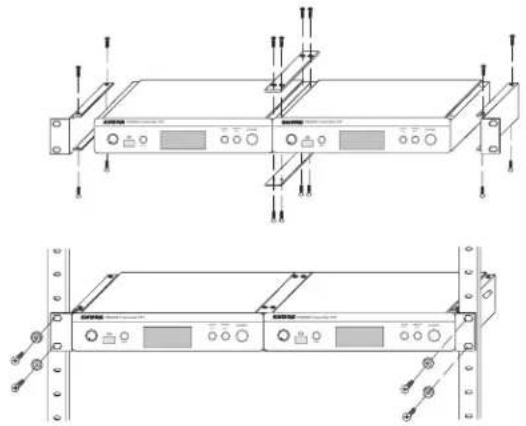
natural_image
Technical line drawing of a rack-mounted server unit with mounting holes and control panel (no text or symbols)natural_image
Line drawing of a SHURE R5000 device with control panel and base mount (no text or symbols on the device itself)natural_image
Line drawing of a hand operating a device with a screen and control buttons (no text or symbols visible)MixMode
Service : Homologation EMA
Jakob-Dieffenbacher-Str. 12
natural_image
Line drawing of a multi-pin electronic device with switches and ports (no text or symbols)natural_image
Line drawing of a control panel with multiple switches and a rectangular tray (no text or symbols)natural_image
Technical line drawings of a server rack with control panel and drive unit (no text or symbols)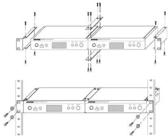
natural_image
Technical line drawings of a rack-mounted server unit with mounting brackets and control panel (no text or symbols)natural_image
Line drawing of a SHURE R50000 device with control panel and base tray (no text or symbols on device body)natural_image
Line drawing of a hand operating a handheld electronic device with control buttons (no text or symbols visible)natural_image
Simple line drawing of a mechanical component with a cylindrical part and a pin, labeled 'SHURE' at the base (no text or symbols on the diagram itself)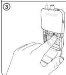
natural_image
Line drawing of a hand inserting a device into a mobile phone (no text or symbols visible)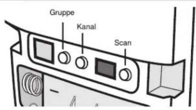
natural_image
Line drawing of a SHURE R5000 device with control panel and base mount (no text or symbols on the device itself)natural_image
Line drawing of a hand operating a device with a screen and control buttons (no text or symbols visible)natural_image
Simple line drawing of a mechanical component with a cylindrical part and a pin, labeled 'SHURE' at the base (no text or symbols on the diagram itself)43 x 198 x 172 mm (1.7 x 7.8 x 6.8 mm), H x B x T
Leistungsbedarf
12-15 V DC, 260 mA Maximal
Audioeingang
Steckertyp
6,35 mm TRS
Polarität
*Non incluse in Argentina
Pannello anteriore del P3T
Pannello posteriore del P3T
natural_image
Technical line drawings of a server rack with control panel and drive unit (no text or symbols)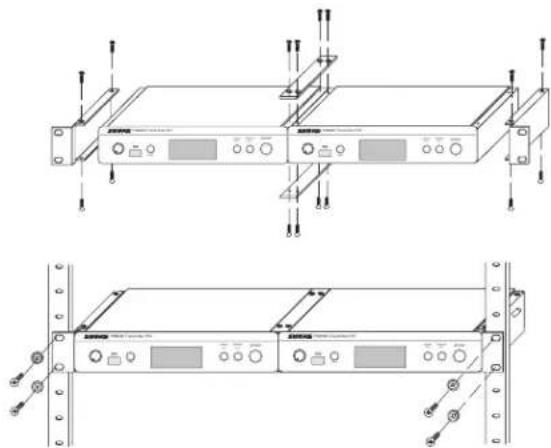
natural_image
Technical line drawings of a rack-mounted server unit with mounting brackets and control panel (no text or symbols)natural_image
Line drawing of a SHURE device with control panel and base, no text or symbols presentnatural_image
Line drawing of a hand interacting with a device labeled 'Micro Device Control Unit' (no text or symbols on the device itself)natural_image
Simple line drawing of a mechanical component with a cylindrical part and a pin, labeled 'SHURE' at the base (no text or symbols on the diagram itself)Department: EMEA Approval
Jakob-Dieffenbacher-Str. 12
75031 Eppingen, Germania
Telefono: 49-7262-92 49 0
Fax: 49-7262-92 49 11 4
E-mail: EMEAsupport@shure.de
P3T
P3T-voorpaneel
P3T-achterpaneel
① Ingangsniveauregeling
⑬ BNC-antenneconnector
natural_image
Technical line drawings of a rack-mounted electronic device with mounting brackets and control panel (no text or symbols)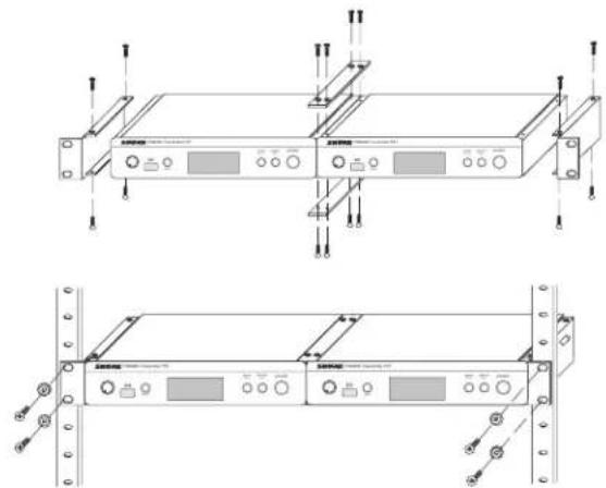
natural_image
Technical line drawings of a rack-mounted server unit with mounting holes and control panel (no text or symbols)natural_image
Line drawing of a SHURE PSM00 device with control panel and base tray (no text or symbols on device)natural_image
Line drawing of a hand operating a device with a screen and control buttons (no text or symbols visible)natural_image
Simple line drawing of a mechanical component with a cylindrical part and a pin, labeled 'SHURE' at the base (no text or symbols on the diagram itself)Monitormixen maken
Painel Frontal do P3T
Painel Traseiro do P3T
natural_image
Technical line drawings of a server rack unit with mounting flanges and control panel (no text or symbols)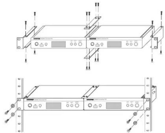
natural_image
Technical line drawings of a rack-mounted server unit with mounting hardware (no text or symbols)natural_image
Line drawing of a SHURE device with control panel and base, no text or symbols presentnatural_image
Line drawing of a hand interacting with a device labeled 'Pulse Transientive PCR' (no text or symbols on the device itself)natural_image
Simple line drawing of a mechanical component with a cylindrical part and a pin, labeled 'SHURE' at the base (no text or symbols on the diagram itself)ref. ±34 kHz de desvio a 1 kHz
<0.5% (típico)
Compressão-Expansão
Headquarters Europe, Middle East & Africa
Department: EMEA Approval
Jakob-Dieffenbacher-Str. 12
Передняя панель РЗТ
Задняя панель РЗТ
natural_image
Illustration of a person singing on a platform (no text or symbols present)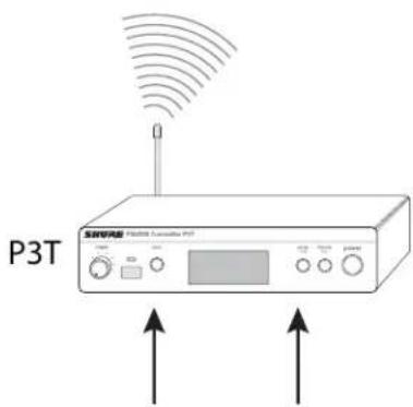
natural_image
Line drawing of a multi-pin electronic device with switches and ports (no text or symbols)natural_image
Line drawing of a control panel with multiple switches and buttons (no text or symbols)natural_image
Technical line drawings of a rack-mounted electronic device with mounting brackets and control panel (no text or symbols)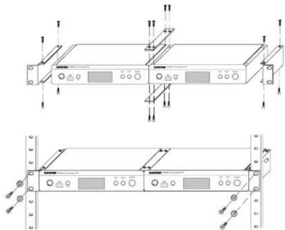
natural_image
Technical line drawings of a rack-mounted server unit with mounting hardware (no text or symbols)natural_image
Line drawing of a SHURE device with control panel and base unit (no text or symbols on the device itself)natural_image
Line drawing of a hand operating a handheld electronic device (no text or symbols visible)natural_image
Simple line drawing of a mechanical component with a cylindrical part and a pin, labeled 'SHURE' at the base (no text or symbols on the component itself)Headquarters Europe, Middle East & Africa
Department: EMEA Approval
Jakob-Dieffenbacher-Str. 12
75031 Eppingen, Germany
NOTE: This Radio equipment is intended for use in musical professional entertainment and similar applications. This Radio apparatus may be capable of operating on some frequencies not authorized in your region. Please contact your national authority to obtain information on authorized frequencies and RF power levels for wireless microphone products.
©2014 Shure Incorporated
United States, Canada, Latin
America, Caribbean:
Shure Incorporated
5800 West Touhy Avenue
Niles, IL 60714-4608 USA
Phone: 847-600-2000
Fax: 847-600-1212 (USA)
Fax: 847-600-6446
Email: info@shure.com
Europe, Middle East, Africa:
Shure Europe GmbH
Jakob-Dieffenbacher-Str. 12,
75031 Eppingen, Germany
Phone: 49-7262-92490
Fax: 49-7262-9249114
22/F, 625 King's Road
North Point, Island East
Hong Kong
Phone: 852-2893-4290
Fax: 852-2893-4055
- IMPORTANT SAFETY INSTRUCTIONS
- SAFETY PRECAUTIONS
- CAUTION
- WARNING
- Important Product Information
- LICENSING INFORMATION
- Information to the user
- PSM®300
- Features
- P3T Transmitter Front and Rear Panels
- P3T Transmitter Display
- P3RA Receiver
- ① Display
- ② Group Button
- ③ Channel Button
- ④ IR Sync Window
- ⑤ Scan Button
- ⑥ Antenna
- ⑦ Power LED Indicator
- ⑧ Power Switch / Volume Control Knob
- ⑨ RF LED Indicator (blue)
- ⑩ Headphone Output
- ⑪ MixMode Control Knob
- ⑫ Battery Compartment
- Applications
- Single System for an Individual Performer
- Single Transmitter with Multiple Receivers
- MixMode or Stereo Operation:
- Multiple Transmitters with Separate Mixes
- Signal Routing to External Devices (Combination Systems)
- Using the PSM300 simultaneously with Loudspeakers:
- Using the PSM300 Combined with Other Wireless Monitoring Systems
- System Setup and Configuration
- Rack Mounting
- Power, Audio, and RF Connections
- Scanning for the Best Open Channel
- Creating a Wireless Connection Between Receivers and Transmitters (Sync)
- Single Transmitter and Receiver
- Sync from receiver to transmitter:
- Single Transmitter and Multiple Receivers
- Sync from transmitter to receivers:
- Multiple Transmitters and Multiple Receivers
- Manual Selection
- Adjusting Gain and Listening Volume
- ① Adjust Transmitter Levels:
- Input Sensitivity
- Input Level
- ② Adjust Receiver Volume:
- Creating Monitor Mixes
- ① Mixer Channel
- ② Monitor/Auxiliary Sends
- ③ Wireless Transmission
- MixMode and Stereo Monitoring
- Selecting the Mode
- Stereo
- MixMode
- Adjusting mix levels
- When to Use the Mono Setting
- Specifications
- PSM300
- RF Carrier Range
- Compatible Frequencies
- Tuning Bandwidth
- Operating Range
- Audio Frequency Response
- Signal-To-Noise Ratio
- Total Harmonic Distortion
- Companding
- Spurious Rejection
- Frequency Stability
- MPX Pilot Tone
- Modulation
- Operating Temperature
- P3R
- Active RF Sensitivity
- Image Rejection
- Adjacent Channel Rejection
- Intermodulation Attenuation
- Blocking
- Audio Output Power
- Minimum Load Impedance
- Headphone Output
- Net Weight
- Dimensions
- Battery Life
- P3T
- RF Output Power
- RF Output Impedance
- Power Requirement
- Audio Input
- Connector Type
- Polarity
- Configuration
- Impedance
- Nominal Input Level
- Pin Assignments
- Phantom Power Protection
- Audio Output
- Certifications
- Australia Warning for Wireless
- Frequency Range and Transmitter Output Power
- CONSIGNES DE SÉCURITÉ IMPORTANTES
- Leistungsbedarf
- Audioeingang
- Steckertyp
- Polarität
- ① Ingangsniveauregeling
- ⑬ BNC-antenneconnector
- Monitormixen maken
- Compressão-Expansão
Brand : SHURE
Model : P3R
Category : Microphone