ZVC30LSS - Range hood Monogram - Free user manual and instructions
Find the device manual for free ZVC30LSS Monogram in PDF.


| Product type | Range hood |
| Brand | Monogram |
| Model | ZVC30LSS |
| Width | 76.2 cm (30 inches) |
| Depth | 61 cm (24 inches) |
| Height (minimum / maximum) | 76.2 cm / 122 cm |
| Net weight | 34 kg |
| Power supply | 120 V ~ 60 Hz, 15 A |
| Total power | 600 W |
| Number of speeds | 4 |
| Lighting | 2 halogen bulbs of 50 W each |
| Filters | Aluminum mesh grease filters, dishwasher safe |
| Venting type | Vertical or horizontal duct (diameter 15.2 cm) |
| Maximum airflow | 485 m³/h |
| Noise level | 36 to 58 dB(A) depending on speed |
| Special features | Timer, filter cleaning reminder, remote control included |
| Maintenance and cleaning | Clean filters every month; wipe exterior with a soft cloth |
| Safety | Automatic shut-off in case of overheating; child safety system (key lock) |
| Spare parts and repairability | Filters, bulbs and remote control available on the manufacturer's website |
| Warranty | 2 years parts and labor |
Frequently Asked Questions - ZVC30LSS Monogram
User questions about ZVC30LSS Monogram
0 question about this device. Answer the ones you know or ask your own.
Ask a new question about this device
Download the instructions for your Range hood in PDF format for free! Find your manual ZVC30LSS - Monogram and take your electronic device back in hand. On this page are published all the documents necessary for the use of your device. ZVC30LSS by Monogram.
USER MANUAL ZVC30LSS Monogram
Installation Instructions
Custom Hood Inserts
these instructions completely and carefully.
- IMPORTANT - Save these instructions for local inspector's use.
- IMPORTANT - Observe all governing codes and ordinances.
- Note to Installer – Be sure to leave these instructions with the Consumer.
- Note to Consumer – Keep these instructions for future reference.
- Skill Level – Installation of this vent hood requires basic mechanical and electrical skills.
- Completion time – 1 to 3 hours.
- Proper installation is the responsibility of the installer.
- Product failure due to improper installation is not covered under the Warranty.
For Monogram local service in your area, call 1.800.444.1845.
For Monogram service in Canada, call 1.800.561.3344.
For Monogram Parts and Accessories, call 1.800.626.2002.

CAUTION:
Due to the weight and size of these vent hoods and to reduce the risk of personal injury or damage to the product, TWO PEOPLE ARE REQUIRED FOR PROPER INSTALLATION.

WARNING:
To reduce the risk of fire or electrical shock, do not use this range hood with any external solid-state speed control device. Any such alteration from original factory wiring could result in damage to the unit and/or create an electrical safety hazard.
TO REDUCE THE RISK OF FIRE, USE ONLY METAL DUCTWORK.

WARNING: TO REDUCE THE RISK OF
FIRE, ELECTRIC SHOCK OR INJURY TO PERSONS, OBSERVE THE FOLLOWING:
A. Use this unit only in the manner intended by the manufacturer. If you have questions, contact the manufacturer.
B. Before servicing or cleaning unit, switch power off at service panel and lock the service disconnecting means to prevent power from being switched on accidentally. When the service disconnecting means cannot be locked, securely fasten a prominent warning device, such as a tag, to the service panel.

CAUTION: For General Ventilating
Use Only. Do Not Use To Exhaust Hazardous Or Explosive Materials And Vapors.

WARNING: TO REDUCE THE RISK OF
FIRE, ELECTRIC SHOCK OR INJURY TO PERSONS, OBSERVE THE FOLLOWING:
A. Installation work and electrical wiring must be done by qualified person(s) in accordance with all applicable codes and standards, including fire-rated construction.
B. Sufficient air is needed for proper combustion and exhausting of gases through the flue (chimney) of fuel burning equipment to prevent back drafting. Follow the heating equipment manufacturer's guideline and safety standards such as those published by the National Fire Protection Association (NFPA), and the American Society for Heating, Refrigeration and Air Conditioning Engineers (ASHRAE), and the local code authorities. When applicable, install any makeup (replacement) air system in accordance with local building code requirements. Visit GEAppliances.com for available makeup air solutions.
C. When cutting or drilling into wall or ceiling, do not damage electrical wiring and other hidden utilities.
D. Ducted fans must always be vented to the outdoors.
- Local codes vary. Installation of electrical connections and grounding must comply with applicable codes. In the absence of local codes, the vent should be installed in accordance with National Electrical Code ANSI/NFPA 70-1990 or latest edition.
CAUTION: To reduce risk of fire and to properly exhaust air, be sure to duct air outside. Do not vent exhaust air into spaces within walls or ceilings or into attics, crawl spaces or garages.
WARNING: TO REDUCE THE RISK OF A RANGE TOP GREASE FIRE:
A. Never leave surface units unattended at high settings. Boilovers cause smoking and greasy spillovers that may ignite. Heat oils slowly on low or medium settings.
B. Always turn hood ON when cooking at high heat or when flambeing food (i.e. Crepes Suzette, Cherries Jubilee, Peppercorn Beef Flambé).
C. Clean ventilating fans frequently. Grease should not be allowed to accumulate on fan or filter.
D. Use proper pan size. Always use cookware appropriate for the size of the surface element.
WARNING: TO REDUCE THE RISK OF INJURY TO PERSONS IN THE EVENT OF A RANGE TOP GREASE FIRE, OBSERVE THE FOLLOWING*:
A. SMOTHER FLAMES with a close-fitting lid, cookie sheet or metal tray, then turn off the burner. BE CAREFUL TO PREVENT BURNS. If the flames do not go out immediately, EVACUATE AND CALL THE FIRE DEPARTMENT.
B. NEVER PICK UP A FLAMING PAN—You may be burned.
C. DO NOT USE WATER, including wet dishcloths or towels—a violent steam explosion will result.
D. Use an extinguisher ONLY if:
1) You know you have a Class ABC extinguisher, and you already know how to operate it.
2) The fire is small and contained in the area where it started.
3) The fire department is being called.
4) You can fight the fire with your back to an exit.
*Based on "Kitchen Firesafety Tips" published by NFPA.
CONTENTS
Design Information
Product Clearances 4
Product Dimensions 5-8
Advance Planning
Advance Planning 9
Remote Mounting of the Control (Wired) 9
Power Supply 9
Duct Fittings 10
Installation Preparation
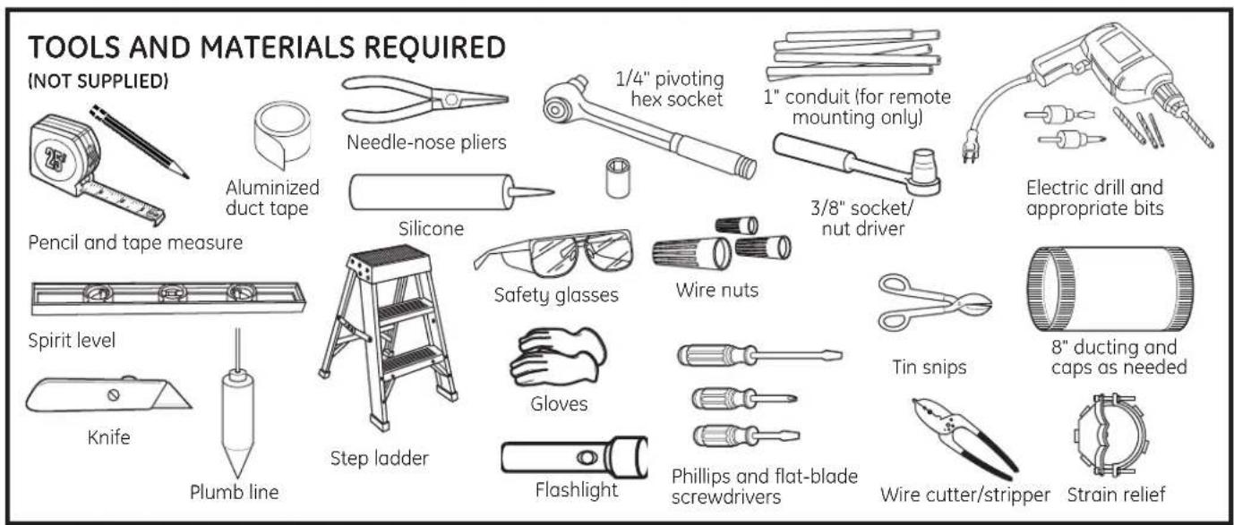
Tools and Materials Required 11
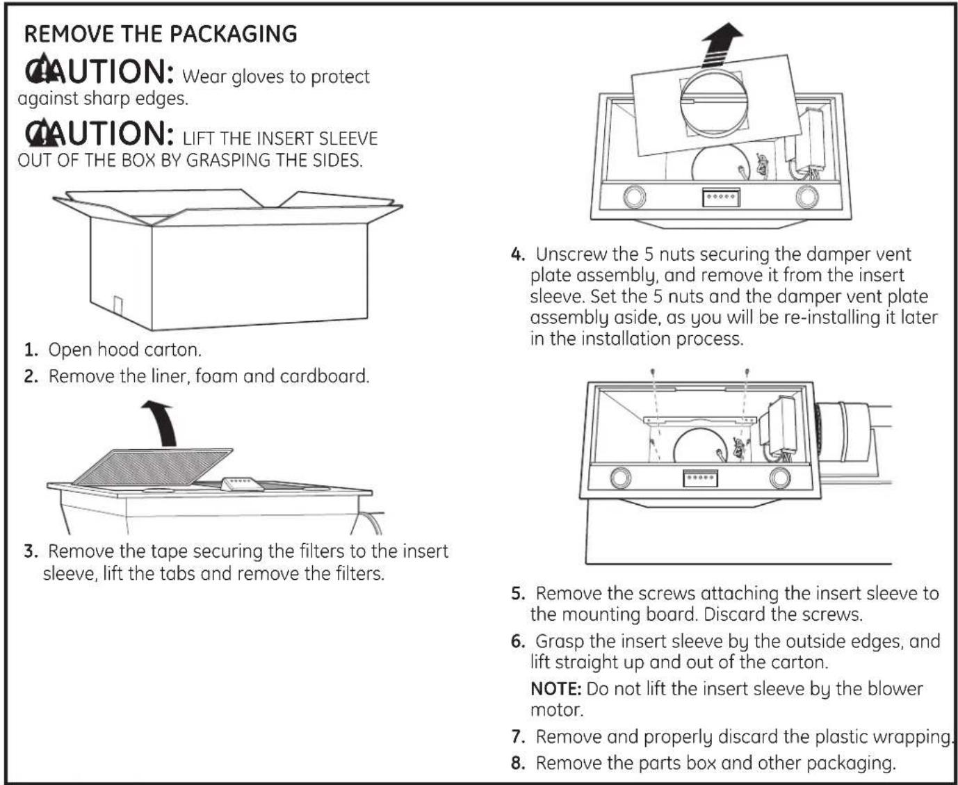
Remove the Packaging 11
Parts Provided 12
Ductwork, Wiring Locations 13
Construct Ceiling Support 14
Remote Mounting of the Control - Wired 15, 16
Installation Instructions
Step 1, Install Hood Liner .....17
Step 2, Connect Electrical ....18
Step 3, Install Insert Sleeve ....19
Step 4, Install Damper Plate ....20
Step 5, Install Blower Motor ....21
Step 6, Connect Wiring Harness ....21
Step 7, Install Filters ....22
Step 8, Finalize Installation ....22
PRODUCT CLEARANCES
The vent hood and liner assembly must be installed 30" minimum and 36" maximum above the cooking surface.
- Always refer to the cooktop or range installation instructions for product-specific clearances.
NOTE: Installation height should be measured from the cooking surface to the bottom edge of the metal hood liner or cabinet surface.
NOTE: UL requires any combustible surface to be a minimum of 30 ≤ above the cooking surface.
- This hood must be vented to the outdoors.
- This hood may be mounted onto a wall or installed over an island.
- This hood can be installed over any Monogram electric/gas cooktop or Monogram Professional cooktop or range of equivalent width.
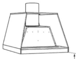
natural_image
Line drawing of a 3D architectural structure resembling a chimney or duct (no text or symbols)*30" Minimum required
*36" Maximum recommended
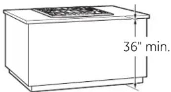
* NOTE: Rear wall exhaust venting may affect installation height. See page 13.
PRODUCT DIMENSIONS
ZVC30
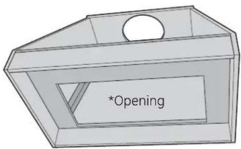
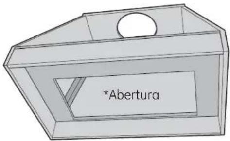
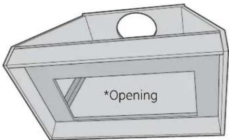
The custom canopy must be sized to fit the insert sleeve. Construct the canopy with an opening that is:
26"W × 13-3/16"D
The opening must be constructed of 3/4" thick material to allow the sleeve locking clips to engage.
The Supplied Liner
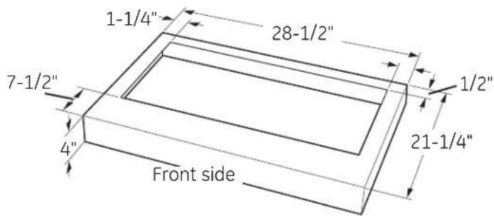
The stainless steel liner is shipped with each hood insert. This non-combustible liner protects the underside of the canopy.
Custom Liner
If you are not using the supplied liner, you may construct a custom non-combustible liner. Use the supplied liner as a template. The opening must be 26"W x 13-3/16"D. 3/4" thick material must surround the opening to allow the sleeve locking clips to engage. The insert sleeve inside the cabinet should be positioned 1/2" from the rear wall so that the center of the 8" duct is 5-1/2" from the rear wall.
Dimensions and Specifications (in inches)
Outside Dimensions
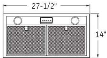
The Insert Sleeve
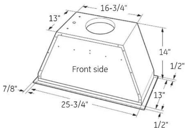
The bottom edge of the insert sleeve has a 7/8" wide flange on the sides and a 1/2" wide flange on the front and back.
Remote Location for the Control
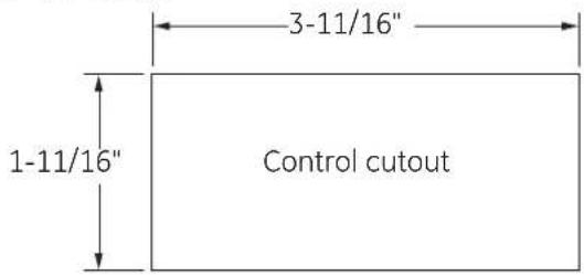
The control may be removed from the hood and installed into a wall or countertop. A 30-ft. length of wire is supplied to accommodate most installations. A blanking plate covers the opening when the controls are removed.
The overall size of the control is 4-1/4" wide and 2-1/4" deep.
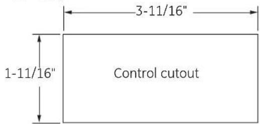
We recommend that the cutout in granite or other hard surfaces be made before the countertop is installed.
PRODUCT DIMENSIONS
ZVC36
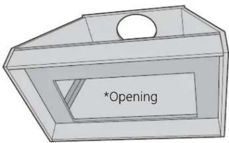
The custom canopy must be sized to fit the insert sleeve. Construct the canopy with an opening that is:
$$ 2 6 ^ {\prime \prime} W \times 1 3 - 3 / 1 6 ^ {\prime \prime} D $$
The opening must be constructed of 3/4" thick material to allow the sleeve locking clips to engage.
The Supplied Liner
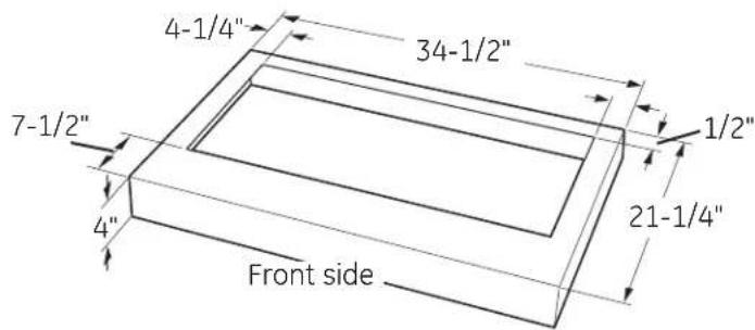
The stainless steel liner is shipped with each hood insert. This non-combustible liner protects the underside of the canopy.
Custom Liner
If you are not using the supplied liner, you may construct a custom non-combustible liner. Use the supplied liner as a template. The opening must be 26"W x 13-3/16"D. 3/4" thick material must surround the opening to allow the sleeve locking clips to engage. The insert sleeve inside the cabinet should be positioned 1/2" from the rear wall so that the center of the 8" duct is 5-1/2" from the rear wall.
Dimensions and Specifications (in inches)
Outside Dimensions
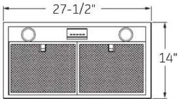
The Insert Sleeve
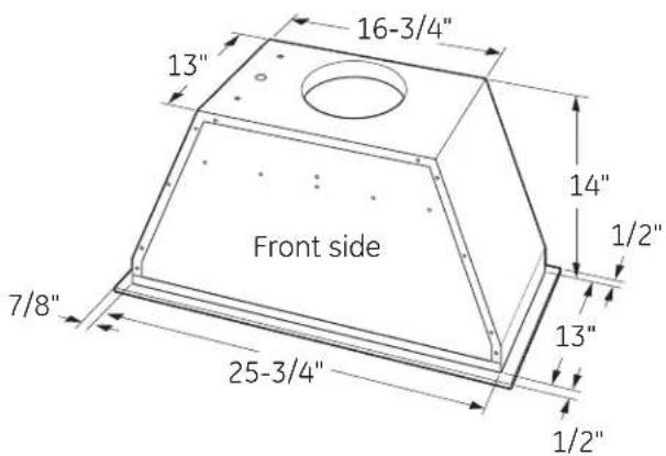
The bottom edge of the insert sleeve has a 7/8" wide flange on the sides and a 1/2" wide flange on the front and back.
Remote Location for the Control
The control may be removed from the hood and installed into a wall or countertop. A 30-ft. length of wire is supplied to accommodate most installations. A blanking plate covers the opening when the controls are removed.
The overall size of the control is 4-1/4" wide and 2-1/4" deep.
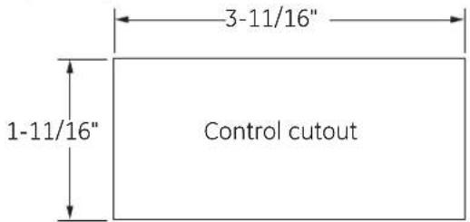
We recommend that the cutout in granite or other hard surfaces be made before the countertop is installed.
PRODUCT DIMENSIONS
ZVC42
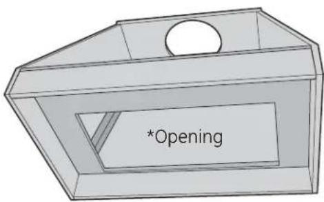
The custom canopy must be sized to fit the insert sleeve. Construct the canopy with an opening that is:
38-3/4"W x 13-3/16"D
The opening must be constructed of 3/4" thick material to allow the sleeve locking clips to engage.
The Supplied Liner
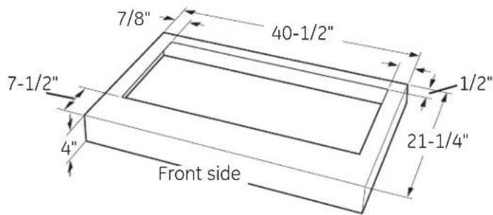
The stainless steel liner is shipped with each hood insert. This non-combustible liner protects the underside of the canopy.
Custom Liner
If you are not using the supplied liner, you may construct a custom non-combustible liner. Use the supplied liner as a template. The opening must be 38-3/4"W x 13-3/16"D. 3/4" thick material must surround the opening to allow the sleeve locking clips to engage. The insert sleeve inside the cabinet should be positioned 1/2" from the rear wall so that the center of the 8" duct is 5-1/2" from the rear wall.
Dimensions and Specifications (in inches)
Outside Dimensions
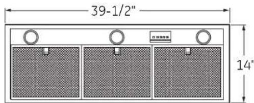
The Insert Sleeve
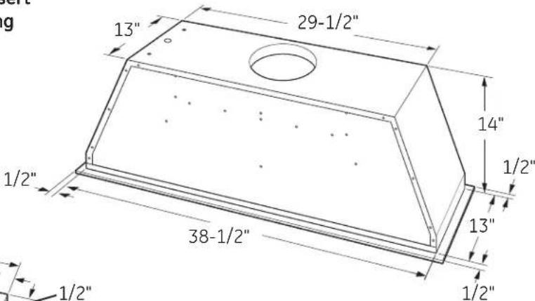
A 1/2" wide flange surrounds the outside edge of the insert sleeve.
Remote Location for the Control
The control may be removed from the hood and installed into a wall or countertop. A 30-ft. length of wire is supplied to accommodate most installations. A blanking plate covers the opening when the controls are removed.
The overall size of the control is 4-1/4" wide and 2-1/4" deep.
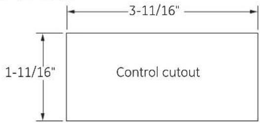
We recommend that the cutout in granite or other hard surfaces be made before the countertop is installed.
PRODUCT DIMENSIONS
ZVC48
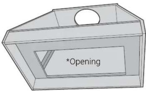
The custom canopy must be sized to fit the insert sleeve. Construct the canopy with an opening that is:
38-3/4"W x 13-3/16"D
The opening must be constructed of 3/4" thick material to allow the sleeve locking clips to engage.
The Supplied Liner
The stainless steel liner is shipped with each hood insert. This non-combustible liner protects the underside of the canopy.
Custom Liner
If you are not using the supplied liner, you may construct a custom non-combustible liner. Use the supplied liner as a template. The opening must be 38-3/4"W x 13-3/16"D. 3/4" thick material must surround the opening to allow the sleeve locking clips to engage. The insert sleeve inside the cabinet should be positioned 1/2" from the rear wall so that the center of the 8" duct is 5-1/2" from the rear wall.
Dimensions and Specifications (in inches)
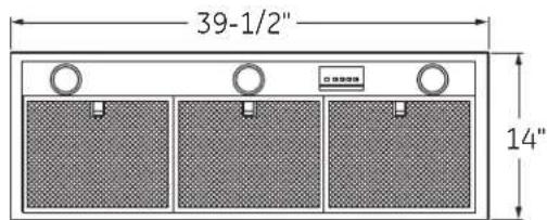
Outside Dimensions
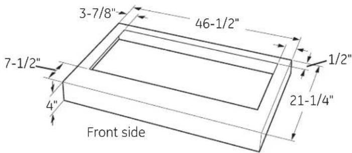
The Insert Sleeve
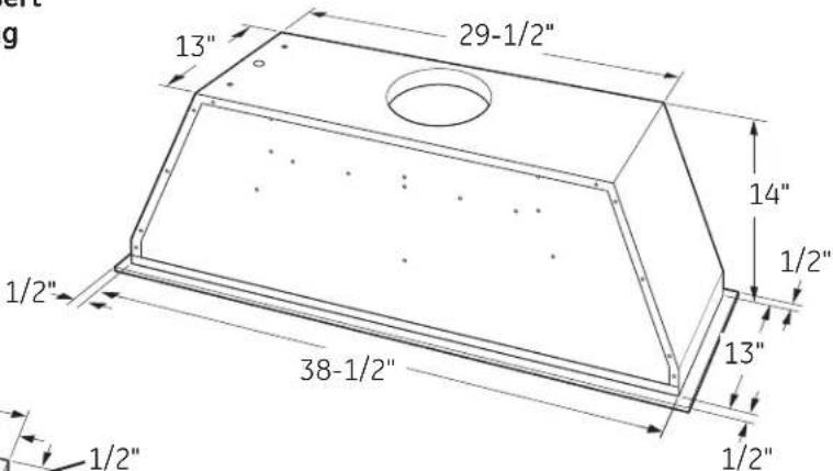
A 1/2" wide flange surrounds the outside edge of the insert sleeve.
Remote Location for the Control
The control may be removed from the hood and installed into a wall or countertop. A 30-ft. length of wire is supplied to accommodate most installations. A blanking plate covers the opening when the controls are removed.
The overall size of the control is 4-1/4" wide and 2-1/4" deep.
We recommend that the cutout in granite or other hard surfaces be made before the countertop is installed.
ADVANCE PLANNING
Ductwork Planning
- This hood is equipped for 8" round ductwork.
- Determine the exact location of the vent hood.
- Plan the route for venting exhaust to the outdoors. This hood is not designed for a recirculating venting operation.
- Use the shortest and straightest duct route possible. For satisfactory performance, duct run should not exceed 100 ft. equivalent length for any duct configurations.
- Refer to "Duct Fittings" chart to compute the maximum permissible length for duct runs to the outdoors.
- Use rigid metal ductwork only.
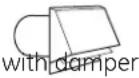
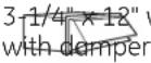
- Install a wall or roof cap with damper at the exterior opening. Order the cap and any transitions needed in advance.
- When applicable, install any makeup (replacement) air system in accordance with local building code requirements. Visit GEAppliances.com for available makeup air solutions.
Wall and Ceiling Framing for Adequate Support
This vent hood is heavy and the cabinet structure needs to support the weight of the loaded insert sleeve. Adequate structural support must be provided in all types of installations.
- Installation will be easier if the vent hood is installed before the cooktop is installed.
Custom Cabinet Frame Planning
- The custom-built canopy should be sized to accommodate the hood insert sleeve. See pages 5–9 for details.
Remote Mounting of the Control (Wired)
- The control can be remotely mounted on the wall or the countertop.
- It is recommended that you use a professional installer for the countertop cutout.
- It is recommended that the cutout in a granite countertop or other hard surface be made before the countertop is installed.
- The cutout needs to be made at least 6 inches from the edges of the countertop.
- If mounting in the countertop above a drawer, consideration must be given to the depth of the control mounting assembly.
- A 30 ft. wire cord is provided. Careful consideration must be given to the location of the remotely mounted control.
- It is recommended that the 4-wire cord be routed through 1" conduit between the insert sleeve and the remote mounting location.
POWER SUPPLY
IMPORTANT - (Please read carefully)
WARNING:
FOR PERSONAL SAFETY, THIS APPLIANCE MUST BE PROPERLY GROUNDED.
Remove house fuse or open circuit breaker before beginning installation.
Do not use an extension cord or adapter plug with this appliance. Follow National electrical codes or prevailing local codes and ordinances.
Electrical Supply
This vent hood must be supplied with 120V, 60Hz, and connected to an individual, properly grounded branch circuit, and protected by a 15 or 20 amp circuit breaker or time delay fuse.
- Wiring must be 2 wire with ground.
- For supply connection, use wires suitable for at least 75°C (167°F).
- If the electrical supply does not meet the above requirements, call a licensed electrician before proceeding.
- Route house wiring as close to the installation location as possible, in the ceiling or back wall.
- Connect the hood wiring to the house wiring in accordance with local codes.
- House wiring must extend to 45" minimum from bottom of cabinet in order to make connection to hood wiring.
Grounding Instructions
The grounding conductor must be connected to a grounded metal, permanent wiring system, or an equipment-grounding terminal or lead on the hood.
WARNING: The improper connection of the equipment-grounding conductor can result in a risk of electric shock. Check with a qualified electrician or service representative if you are in doubt whether the appliance is properly grounded.
DUCT FITTINGS
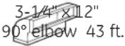
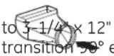
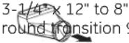
This Hood Must Use an 8" Round Duct. It Can Transition to a 3-1/4" x 12" Duct.
Use this chart to compute maximum permissible lengths for duct runs to outdoors.
NOTE: Do not exceed maximum permissible equivalent lengths!
Maximum duct length: 100 foot for range hoods.
Flexible ducting:
If flexible metal ducting is used, all the equivalent feet values in the table should be doubled. The flexible metal duct should be straight and smooth and extended as much as possible.
DO NOT use flexible plastic ducting.
NOTE: Any home ventilation system, such as a ventilation hood, may interrupt the proper flow of combustion air and exhaust required by fireplaces, gas furnaces, gas water heaters and other naturally vented systems. To minimize the chance of interruption of such naturally vented systems, follow the heating equipment manufacturer's guidelines and safety standards such as those published by NFPA and ASHRAE. When applicable, install any makeup (replacement) air system in accordance with local building code requirements. Visit GEAppliances.com for available makeup air solutions.
| Duct Piece | Dimensions | Length* | Used Length | Equivalent | Quantity |
 | Round, straight | 1(per length) | ft. foot | ||
3 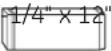 | 1 ft. straight | (per length) | foot | ||
| 90° | elbow | 17 | ft. | ||
 | 45° | elbow | 10 | ft. | |
 | |||||
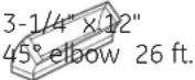 | |||||
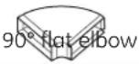 | 3-1/4" | × 102 ft. | 12" | ||
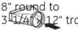 | insition | 2 ft. | |||
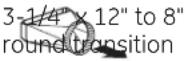 | 5 ft. | ||||
 | 8" | round | |||
| !bow | 6 ft. | ||||
 | 30° elbow | 13 ft. | |||
 | Round wall | cap | |||
| 32 ft. | |||||
 | wall cap | 75 ft. | |||
 | Round | 44 ft. | |||
| *Actual length of straight duct plus duct fitting equivalent. Equivalent length of duct pieces are based on actual tests conducted by GE Evaluation Engineering and reflect requirements for good venting performance with any ventilation hood. | Total Duct Run____ | ||||
*Actual length of straight duct plus duct fitting equivalent. Equivalent length of duct pieces are based on actual tests conducted by GE Evaluation Engineering and reflect requirements for good venting performance with any ventilation hood. Total Duct Run____
PARTS PROVIDED
Locate the parts packed with the hood.
CHECK INSTALLATION HARDWARE
Count screws/ components. Screws shown actual size.
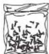


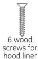
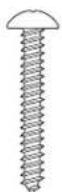
8 wood screws for insert sleeve
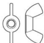
2 wing nuts with lock washers for blower motor
5 nuts for damper plate assembly (not located in hardware bag-you must save nuts when you remove damper plate from inset hood while unpacking parts)
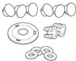
natural_image
Technical line drawings of mechanical components including gears, a washer, and washers (no text or labels)6 insert sleeve chassis plugs, 1 (optional) house wire hole plug, 2 rubber grommets, 4 insert sleeve washers
REMOTE MOUNTING OF THE CONTROL (WIRED)
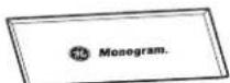
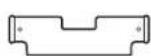
Blanking plate for remote control opening*
* NOTE: To be used on custom hood when controls are remotely mounted.
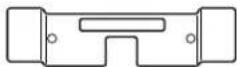
Control wall bracket
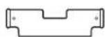
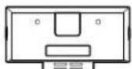
Control mounting plate
Control mounting bracket
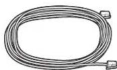

Connector/Converter

2 mounting plate screws
2 wall bracket screws
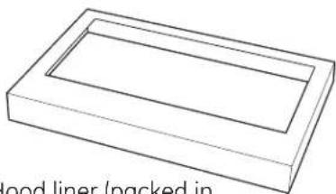
natural_image
Simple line drawing of a rectangular box with a recessed top (no text or symbols)Hood liner (packed in separate carton)
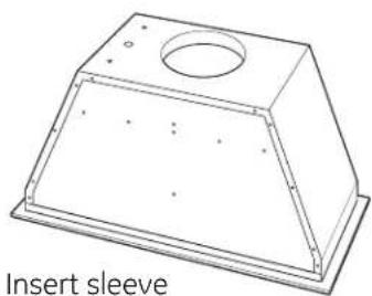
natural_image
Technical line drawing of a mechanical component with a circular opening and base plate (no text or symbols)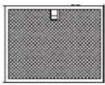
Filters
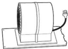
natural_image
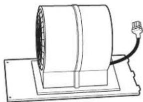
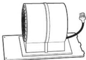
Line drawing of a cylindrical device mounted on a base plate with a cable (no text or symbols)Blower motor (30" and 36" Wide Models)
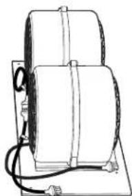
natural_image
Simple line drawing of a cylindrical device with attached wires and connectors (no text or symbols)Dual blower motor (42" and 48" Wide Models)
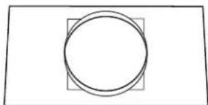
natural_image
Simple geometric diagram showing a circle inscribed in a square, no text or symbols presentDamper plate
DUCTWORK, WIRING LOCATIONS
Determine the exact location of the insert sleeve. Mark the exact centerline location.
The ceiling structure must be capable of supporting the weight of the insert sleeve (approximately 100 pounds), the canopy itself, any mounting hardware and any inadvertent user contact loads.
- Measure from the top of the cooking surface to the bottom edge of the insert sleeve. Add insert sleeve installation height. Mark that location.
- Use a level to draw a straight horizontal pencil line on the wall.
NOTE: House duct should drop to 11-1/2" above bottom edge of insert sleeve.
Location of house duct is important because it must align with vent of damper plate assembly.
Ceiling ducting:
If ductwork will vent straight up to the ceiling:
- Use a level to draw a centerline straight up to the ceiling.
- On the ceiling, measure 5-1/2" from the back wall to the centerline of an 8-1/2" hole.
Rear Wall Ducting: (See important note.) If ductwork will vent to the rear:
- Use a level to draw a centerline straight up to the ceiling.
- Measure at least 22-1/2" above the pencil line that indicates the bottom installation height, to the centerline of an 8-1/2" dia. duct hole. (Hole may be elongated for duct elbow.)
HOUSE WIRING LOCATION:
- The junction box is located inside the top left side of the hood.
- Wiring should enter the back wall at least 15" above the bottom of the insert sleeve, and within 6" of the left side of the centerline.
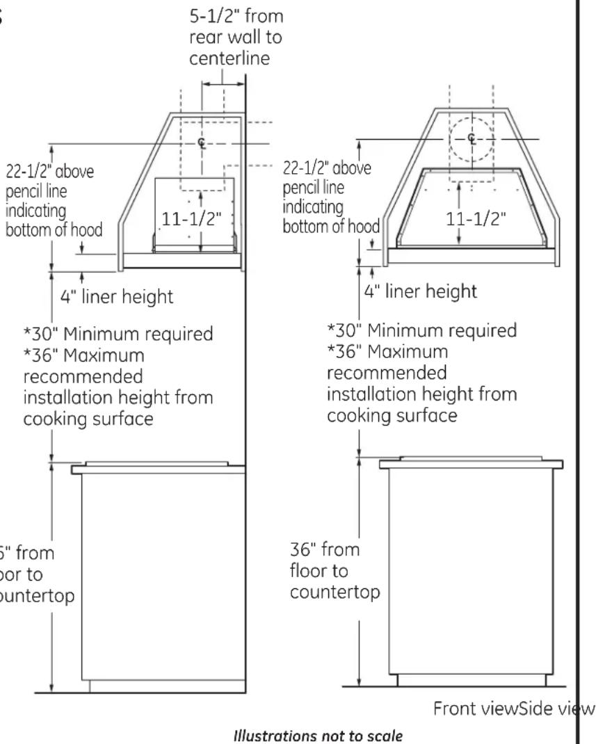
* Always refer to the cooktop or range installation instructions for product-specific clearances.
IMPORTANTNOTE: If you are planning to vent through the rear wall, and the ceiling height is 8 ft., the maximum installation height is 33" above the cooking surface.
CONSTRUCT CEILING SUPPORT (for Island Installation)
Plan the Location of the Hood and Ductwork
The ceiling structure must be capable of supporting the weight of the insert sleeve (approximately 100 pounds), the canopy itself, any mounting hardware and any inadvertent user contact loads.
- Use a plumb bob to check the location. The countertop/cooktop below the insert sleeve must be centered with the insert sleeve.
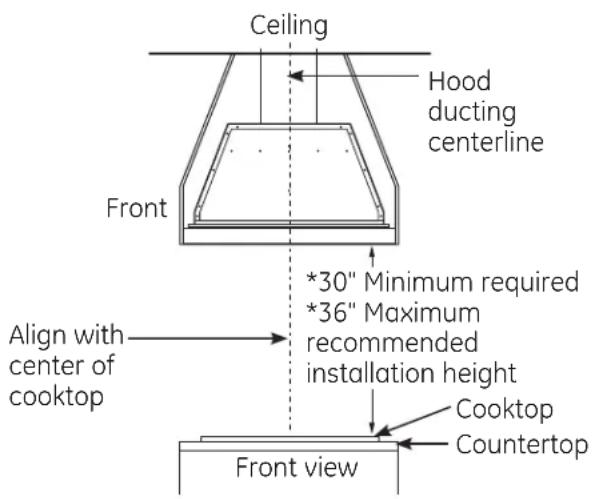
* Always refer to the cooktop or range installation instructions for product-specific clearances.
- The insert sleeve in the canopy must be centered left to right over the cooktop.
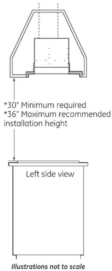
- If desired, install the control in a remote location using the supplied mounting hardware. See the following pages for detailed instructions for mounting the control remotely.
- Refer to Ceiling Ducting on page 13 for ductwork installation.
IMPORTANT: The exhaust outlet in the top of the insert sleeve is not centered; it is positioned closer to the back side. Therefore, the insert sleeve may not be centered front to back in the canopy. A custom liner constructed by the cabinet supplier is usually required for island installations.
NOTE: It is recommended that the custom hood insert be purchased and on-site before the canopy is constructed.
REMOTE MOUNTING OF THE CONTROL - WIRED

WARNING:
Disconnect electrical
power from unit before beginning remote control installation. Failure to do so could result in personal injury or damage to the electrical controls.
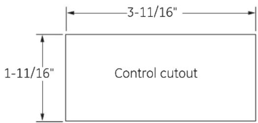
REMOTE LOCATION FOR CONTROL
NOTE: The hood is only certified for use with the supplied 30-ft. length of wire.
The control can be removed from the hood and installed in a backsplash or countertop.
- A cover plate is provided to cover the opening in the hood when the control is removed.
- A 30-ft. length of 4-wire cord is supplied to accommodate most installations. Because only 30-ft. of cord is provided, careful consideration must be given to the location of the remotely mounted control.
- The 30-ft. cord is supplied with a connector/ converter on one end. DO NOT REMOVE the connector/converter from the 30-ft. cord. Failure to use the connector/converter with the shorter cord will prevent proper operation of the control.
NOTE: Not for telecommunication (telephone) network.
- The cord must be routed through the holes in the insert sleeve, and the rubber grommets put into place around the cord.
NOTE: On the ZVC30 and ZVC36 models, the cord needs to be routed through the holes in the insert sleeve before the damper plate is installed.
- Route the cord through the conduit to reach the installation location of the control.
Remotely Mounted Control—Wall or Countertop Installation

REMOTE MOUNTING OF THE CONTROL – WIRED (Continued)
COUNTERTOP
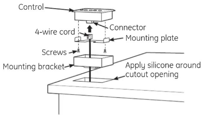
- Cut out opening in the countertop. Cutout dimensions are 1-11/16" x 3-11/16".
- Loosen the 4 thumbscrews and remove the control from the insert sleeve. Replace the control with the blanking plate provided.
- Attach the mounting plate to the back of the control with the 2 mounting plate screws.
- Pull the 4-wire cord through the opening in the countertop, and through the back of the mounting bracket.
NOTE: Use provided cables and connector/converter ONLY.
- Connect the 4-wire cord to the jack of the connector on the remotely mounted control.
- Press the control firmly into the mounting bracket so that the clips engage.
- Apply silicone around the cutout opening.
- Insert the control into the cutout opening.
WALL MOUNT
-
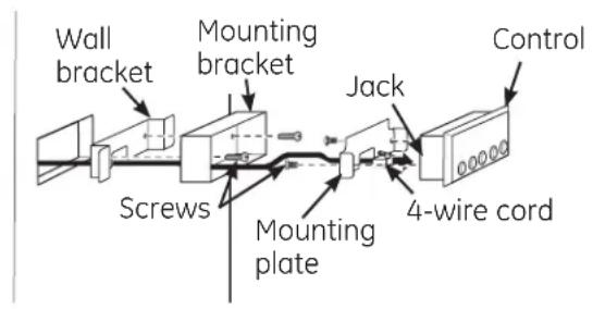
Cut out opening into the wall surface. Cutout dimensions are 1-11/16" x 3-11/16".
-
Loosen the 4 thumbscrews and remove the control from the insert sleeve. Replace the control with the blanking plate provided.
-
Attach the mounting plate to the back of the control with the 2 mounting plate screws.
-
Pull the 4-wire cord through the opening in the wall, the wall bracket and the back of the mounting bracket.
NOTE: Use provided cables and connector/converter ONLY.
- Connect the mounting bracket to the wall bracket using the two wall bracket screws. Only start the first 1-2 threads of the screws into the wall, as you want to leave a gap between the two brackets to account for the wall thickness.
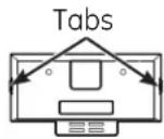
- Raise the tabs on the mounting bracket so the bracket will fit through the wall opening.
- Angle the mounting and wall brackets and slide them through the wall cutout.
NOTE: Attach a string to the brackets, so you can retrieve them from behind the wall if dropped.
- Flatten tabs on mounting bracket so they are flush with the wall surface, and tighten the wall bracket screws to pull the wall bracket flanges flush with the backside surface of the wall.
- Connect the 4-wire cord to the jack of the connector on the remotely mounted control.
- Press the control firmly into the mounting bracket so that the clips engage.
STEP 1 INSTALL HOOD LINER
natural_image
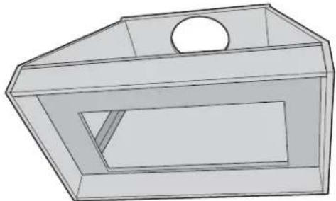
3D technical drawing of a mechanical housing or enclosure with a circular opening and rectangular cutout (no text or symbols)- Frame the cutout opening to fit the liner. NOTE: The opening support must be 3/4" thick wood to accept the liner installation screws.
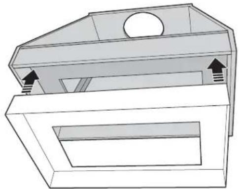
natural_image
Technical line drawing of a mechanical housing or enclosure with internal components and mounting holes (no text or symbols)- Slide the liner up and into the opening until flush with bottom edges.
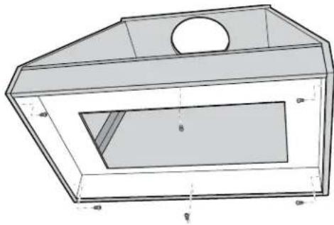
natural_image
Technical line drawing of a 3D mechanical housing or enclosure with internal cutouts and mounting holes (no text or symbols)- Secure the liner to the cabinet with 6 screws provided.
STEP 2 CONNECT ELECTRICAL
Verify that power is turned off at the source.
WARNING: If house wiring is not 2-wire with a ground wire, an electrician will need to convert existing wiring to meet these specs. When house wiring is aluminum, be sure to use U.L.-approved anti-oxidant compound and aluminum-to-copper connectors.
- Place insert sleeve on padded, yet stable, surface below cutout (can use flattened carton to pad surface).
- Remove the junction box cover.
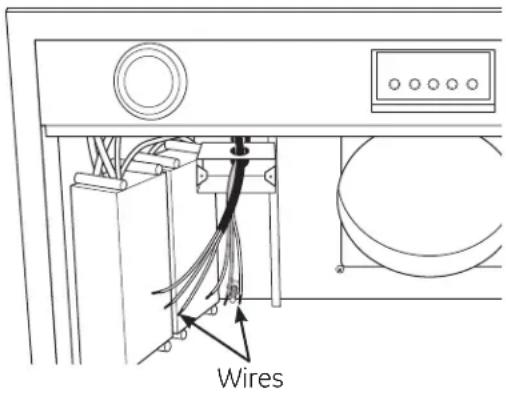
- Pull house wires through wall of insert sleeve and attach the strain relief. Thread the house wire through the junction box.
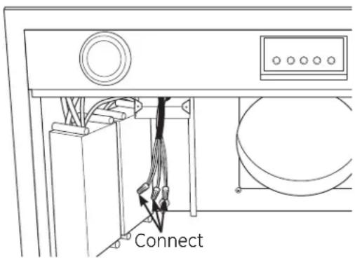
- Connect white leads to branch circuit white lead.
- Connect black leads to branch circuit black lead.
- Connect green/yellow leads to branch circuit green lead.
- Secure all connections with wire nuts.
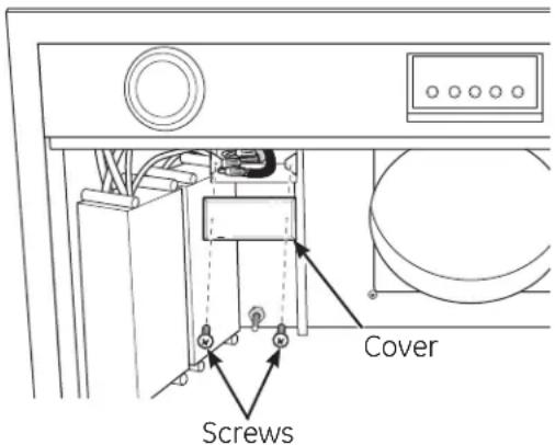
- Carefully push wires into junction box and replace cover.
- Secure junction box cover with original screws.
STEP 3 INSTALL INSERT SLEEVE
natural_image
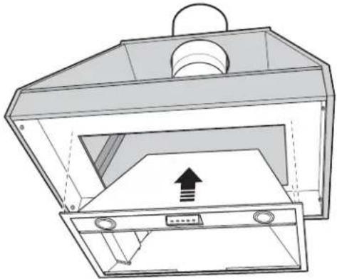
Technical line drawing of a mechanical device with an open lid and internal components, showing no text or symbols.- Tuck the house wiring out of the way.
- Install the insert sleeve into the cutout opening of custom cabinet frame.
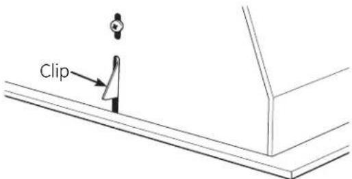
- Push the insert sleeve straight up through the cutout opening until the temporary locking clips engage. The locking clips are designed to hold the insert sleeve in place until it is secured with screws.
NOTE: The locking clips are not designed to support all of the weight of the insert sleeve. Do not leave the insert sleeve unattended until screws have been inserted.
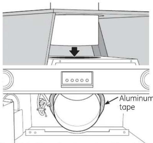
- Align 8" duct to exhaust opening of insert sleeve and seal with aluminum tape.
NOTE: House duct should drop to 11-1/2" above bottom edge of insert sleeve or the bottom of the 3/4" cabinet base.
natural_image
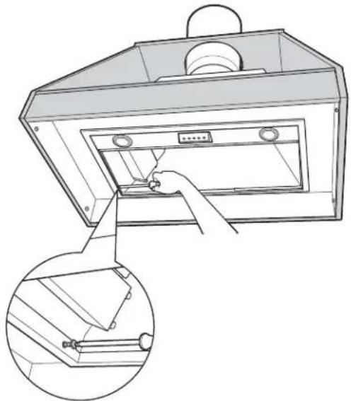
Line drawing of a kitchen appliance with a hand inserting a component into the door, shown in two views (no text or symbols)- Tape the 4 washers in place over the outside of the 4 front and back holes of the insert sleeve. The washers are designed to be located between the insert sleeve and the 3/4≤ cabinet surface.
- Press the sleeve up firmly and secure with the 8 screws provided. The insert sleeve should be flush with the liner and have no visible gaps.
NOTE: It is IMPORTANT to install front mounting screw. The front screw hole is difficult to see and may require you to place your head into the cutout opening to locate.
STEP 4 INSTALL DAMPER PLATE
natural_image
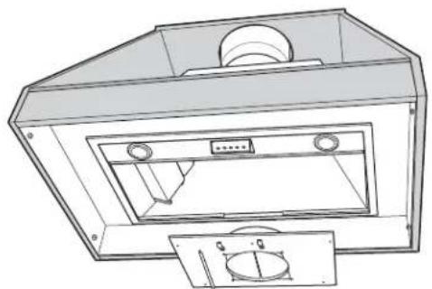
Technical line drawing of a mechanical device with mounting holes and internal components (no text or symbols)- Pick up damper plate assembly and rotate so that vent side is up and bracket is located on left as you stand facing hood.
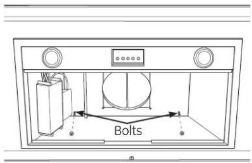
- Secure damper plate assembly by placing nuts on bolts and tightening with socket or wrench.
natural_image
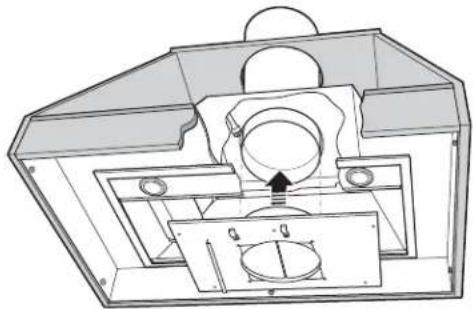
Technical line drawing of a mechanical assembly with no visible text or symbols- Insert damper plate assembly into insert sleeve and carefully align with 8" house duct.
STEP 5 INSTALL BLOWER MOTOR
natural_image
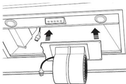
Diagram of a mechanical device with arrows indicating motion or force direction (no text or symbols)- Pick up blower motor and rotate so tabs align with damper plate bracket.
- Insert blower motor into insert sleeve through cutout opening of custom cabinet frame.
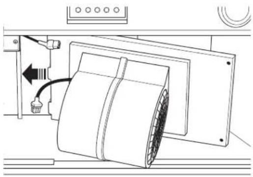
natural_image
Technical line drawing of a mechanical component with a fan-like structure and directional arrow (no text or symbols)- Place blower motor on damper plate assembly by sliding blower motor tabs into slots of damper plate assembly.
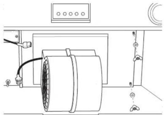
natural_image
Technical line drawing of an electrical enclosure with a motor, wiring, and control panel (no text or symbols)- While holding blower motor in place, lift right side so that blower motor bolt holes align with bolts protruding from damper plate assembly and secure with lock washers and wing nuts (hand tighten).
STEP 6 CONNECT WIRING HARNESS
NOTE: Connect three routing clips and two wiring harnesses on double blower models.
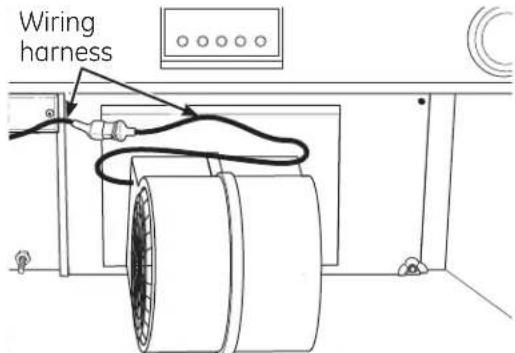
- Locate both ends of wiring harness.
- Connect wiring harness by inserting male into female opening.
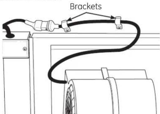
- Carefully route wiring harness and ground wire through two clips attached to blower plate assembly.
STEP 7 INSTALL FILTERS
- Remove protective film from the filters.
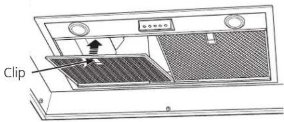
- Tip the filter into the back tab slots and lift up. While maintaining slight backward pressure on filter, open clip and press into place with two hands.
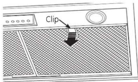
- To remove, support filter with one hand while pulling filter clip down with the other.
STEP 8 FINALIZE INSTALLATION
- Check to be sure all tape and packaging materials have been removed.
- Refer to Owner's Manual for operating instructions.

ANT DE COMMENCER
natural_image
Technical line drawing of a mechanical component with a conical top and flange (no text or symbols)*Minimum de 30 po requis
natural_image
Line drawing of a cardboard box with lid and front panel (no text or symbols)natural_image
Simple line drawing of a printer or printer with an open lid and a black arrow indicating upward motion (no text or symbols)natural_image
Line drawing of a microwave oven with a mounted fan and control panel, showing internal components (no text or symbols)natural_image
Technical line drawing of a front-mounted device with control panel and fan (no text or symbols)Support mural de commandes
natural_image
Simple line drawing of a rectangular box with a recessed top (no text or symbols)natural_image
3D technical drawing of a conical mechanical component with a circular hole and flange (no text or symbols)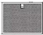
Filtres
natural_image
Line drawing of a cylindrical device mounted on a base with a cable, no text or symbols presentnatural_image
Simple line drawing of a cylindrical device mounted on a base with wires, no text or symbols present.natural_image
Simple geometric diagram showing a circle inscribed in a square, no text or symbols presentnatural_image
Cross-sectional diagram of a mechanical component with dashed lines indicating hidden edges (no text or symbols)natural_image
3D technical drawing of a mechanical housing or enclosure with a circular opening and rectangular cutout (no text or symbols)natural_image
Technical line drawing of a mechanical housing or enclosure with internal components and mounting holes (no text or symbols)natural_image
Technical line drawing of a 3D architectural or mechanical component with no visible text, numbers, or symbols.natural_image
Technical line drawing of a mechanical device with an open lid and internal components, showing no text or symbols.natural_image
Line drawing of a device with an open door and a close-up inset showing internal components (no text or symbols)natural_image
Technical line drawing of a mechanical device with mounting holes and internal components (no text or symbols)natural_image
Technical line drawing of a mechanical assembly with no visible text or symbolsnatural_image
Diagram of a washing machine interior showing fan, control panel, and mechanical components (no text or labels)natural_image
Technical line drawing of a mechanical component with a cylindrical fan and directional arrow (no text or symbols)natural_image
Technical line drawing of an industrial machine with hoses and control panel (no text or symbols)natural_image
Technical line drawing of a mechanical component or housing (no text or symbols)DIMENSIONES DEL PRODUCTO
ZVC30
DIMENSIONES DEL PRODUCTO
ZVC36
DIMENSIONES DEL PRODUCTO
ZVC42
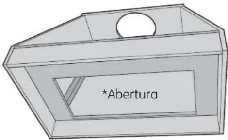
DIMENSIONES DEL PRODUCTO
ZVC48
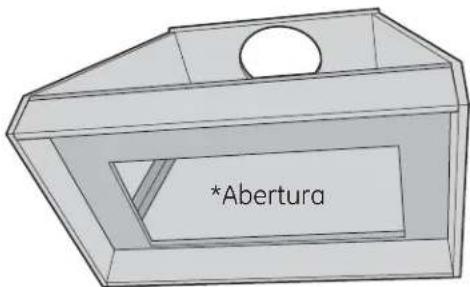
natural_image
Line drawing of a blank cardboard box with no text or symbolsnatural_image
Simple line drawing of a table with an open lid and a black upward arrow indicating motion (no text or symbols)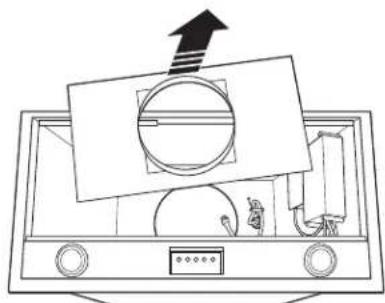
natural_image
Line drawing of a microwave oven with a mounted screen and fan, showing internal components (no text or symbols)natural_image
Technical line drawing of a front-mounted appliance with control panel and door (no text or symbols)natural_image
Simple line drawing of a rectangular box with a recessed top (no text or symbols)natural_image
3D technical drawing of a mechanical component with a circular hole and base plate (no text or symbols)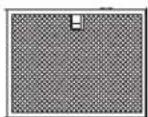
Filtros
natural_image
Line drawing of a cylindrical device mounted on a base with a cable, no text or symbols presentnatural_image
Simple line drawing of a cylindrical device with coiled cable and wiring, no text or symbols presentnatural_image
Simple geometric diagram showing a circle inscribed in a square, no text or symbols presentnatural_image
3D technical drawing of a mechanical housing or enclosure with a circular opening and rectangular cutout (no text or symbols)natural_image
Technical line drawing of a mechanical housing or enclosure with internal components and directional arrows (no text or symbols)natural_image
Technical line drawing of a 3D architectural or mechanical component with no visible text, numbers, or symbols.natural_image
Technical line drawing of a mechanical device with an upward arrow indicating motion or force (no text or symbols present)natural_image
Line drawing of a device with an open lid and a hand inserting a cable into it, shown in two views (no text or symbols present)natural_image
Technical line drawing of a mechanical device with housing and mounting bracket (no text or symbols)natural_image
Technical line drawing of a mechanical assembly with no visible text or symbolsnatural_image
Diagram of a washing machine interior showing fan, control panel, and roller mechanism (no text or labels)natural_image
Technical line drawing of a mechanical device with a rotating fan and housing (no text or symbols)natural_image
Technical line drawing of an air conditioning unit with hoses and control panel (no text or symbols)NOTE: While performing installations described in this book, safety glasses or goggles should be worn.
For Monogram ^® local service in your area, call 1.800.444.1845.
NOTE: Product improvement is a continuing endeavor at General Electric. Therefore, materials, appearance and specifications are subject to change without notice.
- Installation Instructions
- CAUTION:
- WARNING:
- WARNING: TO REDUCE THE RISK OF
- FIRE, ELECTRIC SHOCK OR INJURY TO PERSONS, OBSERVE THE FOLLOWING:
- CAUTION: For General Ventilating
- CONTENTS
- Design Information
- Advance Planning
- Installation Preparation
- PRODUCT CLEARANCES
- PRODUCT DIMENSIONS
- Custom Liner
- Remote Location for the Control
- Ductwork Planning
- Wall and Ceiling Framing for Adequate Support
- Custom Cabinet Frame Planning
- Remote Mounting of the Control (Wired)
- POWER SUPPLY
- Electrical Supply
- Grounding Instructions
- DUCT FITTINGS
- Maximum duct length: 100 foot for range hoods.
- Flexible ducting:
- PARTS PROVIDED
- CHECK INSTALLATION HARDWARE
- DUCTWORK, WIRING LOCATIONS
- NOTE: House duct should drop to 11-1/2" above bottom edge of insert sleeve.
- Ceiling ducting:
- HOUSE WIRING LOCATION:
- CONSTRUCT CEILING SUPPORT (for Island Installation)
- Plan the Location of the Hood and Ductwork
- REMOTE MOUNTING OF THE CONTROL - WIRED
- REMOTE LOCATION FOR CONTROL
- REMOTE MOUNTING OF THE CONTROL – WIRED (Continued)
- NOTE: Use provided cables and connector/converter ONLY.
- NOTE: Attach a string to the brackets, so you can retrieve them from behind the wall if dropped.
- STEP 1 INSTALL HOOD LINER
- STEP 2 CONNECT ELECTRICAL
- STEP 3 INSTALL INSERT SLEEVE
- STEP 4 INSTALL DAMPER PLATE
- STEP 5 INSTALL BLOWER MOTOR
- STEP 6 CONNECT WIRING HARNESS
- STEP 7 INSTALL FILTERS
- STEP 8 FINALIZE INSTALLATION
- ANT DE COMMENCER
- DIMENSIONES DEL PRODUCTO
Brand : Monogram
Model : ZVC30LSS
Category : Range hood