
UVD6301SPSS - Range hood Monogram - Free user manual and instructions
Find the device manual for free UVD6301SPSS Monogram in PDF.

| Product Type | Downdraft Vent System (Range Hood) |
| Brand | Monogram |
| Model | UVD6301SPSS (30") |
| Width | 30 inches |
| Depth | 26-1/4 inches |
| Height (retracted) | Approximately 4 inches (flush with countertop when lowered) |
| Power Supply | 120 V, 60 Hz, 4.0 A |
| Duct Size | 3-1/4" x 10" rectangular (can be transitioned to 6" round) |
| Max Duct Length | 40 feet equivalent |
| Blower Speeds | Variable (adjustable knob) |
| Vent Activation | Press button on top cover to raise/lower; blower auto-shuts off when lowered |
| Filter Type | Grease filters (2 pieces, different sizes) |
| Filter Cleaning | Soak and agitate in hot detergent solution monthly; do not use dishwasher |
| Surface Material | Stainless steel |
| Surface Cleaning | Warm sudsy water or stainless steel cleaner; wipe in direction of grain |
| Grounding | 3-prong grounded plug; 120V grounded outlet required |
| Safety Features | Auto-stop if obstructed; automatic blower shut-off when lowered |
| Warranty | One year limited from date of purchase |
| Installation Type | Countertop mounted, requires custom cutout |
| Discharge Options | Down, left, or right (adjustable) |
| Certifications | Meets safety standards per manual |
Frequently Asked Questions - UVD6301SPSS Monogram
User questions about UVD6301SPSS Monogram
0 question about this device. Answer the ones you know or ask your own.
Ask a new question about this device
Download the instructions for your Range hood in PDF format for free! Find your manual UVD6301SPSS - Monogram and take your electronic device back in hand. On this page are published all the documents necessary for the use of your device. UVD6301SPSS by Monogram.
USER MANUAL UVD6301SPSS Monogram
SAFETY INFORMATION .... 3
USING THE HOOD
Downdraft Vent System .... 5
CARE AND CLEANING
Downdraft Vent System 6
INSTALLATION INSTRUCTIONS..7
TROUBLESHOOTING TIPS ..... 16
LIMITED WARRANTY....17
ACCESSORIES 18
CONSUMER SUPPORT .... 20
OWNER'S MANUAL & INSTALLATION INSTRUCTIONS
UVD6301S
UVD6361S
Write the model and serial numbers here:
Model # ____
Serial # ____
These numbers are also found on the Product Property Registration Card sent separately with your downdraft ventilation system and on the label located on the front panel of the unit.
ESPAÑOL
THANK YOU FOR MAKING GE APPLIANCES A PART OF YOUR HOME.
Whether you grew up with GE Appliances, or this is your first, we're happy to have you in the family.
We take pride in the craftsmanship, innovation and design that goes into every GE Appliances product, and we think you will too. Among other things, registration of your appliance ensures that we can deliver important product information and warranty details when you need them.
Register your GE appliance now online. Helpful websites and phone numbers are available in the Consumer Support section of this Owner's Manual. You may also mail in the pre-printed registration card included in the packing material.

GE APPLIANCES
IMPORTANT SAFETY INFORMATION READ ALL INSTRUCTIONS BEFORE USING
WARNING
TO REDUCE THE RISK OF FIRE, ELECTRIC SHOCK OR INJURY TO PERSONS, OBSERVE THE FOLLOWING:
A. Use this unit only in the manner intended by the manufacturer. If you have questions, contact the manufacturer.
B. Before servicing or cleaning unit, switch power off at service panel and lock the service disconnecting means to prevent power from being switched on accidentally. When the service disconnecting means cannot be locked, securely fasten a prominent warning device, such as a tag, to the service panel.
C. Do not use this unit with any solid-state speed control device.
D. Plug your vent system into a 120-volt grounded outlet only. Do not remove the round grounding prong from the plug. If in doubt about the grounding of the home electrical system, it is your responsibility and obligation to have an ungrounded outlet replaced with a properly grounded, three prong outlet in accordance with the National Electrical Code. Do not use an extension cord with this appliance.
CAUTION
FOR GENERAL VENTILATING USE ONLY. DO NOT USE TO EXHAUST HAZARDOUS OR EXPLOSIVE MATERIALS AND VAPORS.
WARNING
TO REDUCE THE RISK OF INJURY TO PERSONS IN THE EVENT OF A RANGE TOP GREASE FIRE, OBSERVE THE FOLLOWING*:
A. SMOTHER FLAMES with a close-fitting lid, cookie sheet or metal tray, then turn off the burner. BE CAREFUL TO PREVENT BURNS. If the flames do not go out immediately, EVACUATE AND CALL THE FIRE DEPARTMENT.
B. NEVER PICK UP A FLAMING PAN—You may be burned.
C. DO NOT USE WATER, including wet dishcloths or towels—a violent steam explosion will result.
D. Use an extinguisher ONLY if:
- You know you have a Class ABC extinguisher, and you already know how to operate it.
- The fire is small and contained in the area where it started.
- The fire department is being called.
- You can fight the fire with your back to an exit.
* Based on "Kitchen Fire Safety" published by NFPA.
WARNING
TO REDUCE THE RISK OF A RANGE TOP GREASE FIRE:
A. Never leave surface units unattended at high settings. Boilovers cause smoking and greasy spillovers that may ignite. Heat oils slowly on medium settings.
B. Always turn hood ON when cooking at high heat or when flambéing food (i.e. Crepes Suzette, Cherries Jubilee, Peppercorn Beef Flambé).
C. Clean ventilating fans frequently. Grease should not be allowed to accumulate on fan or filter.
D. Use proper pan size. Always use cookware appropriate for the size of the surface element.
If You Need Service...
Do not attempt to repair or replace any part of the vent system unless it is specifically recommended in this manual. All other servicing should be referred to a qualified technician.
Be sure electrical power is off before servicing the unit. It may be necessary to remove the vent system blower system in order to service components such as the blower motor or air vent mechanism.
Disconnect power to the cooktop and remove it first. Reverse the steps in the Install Downdraft Vent section in the Installation Instructions to remove the blower.
Service parts are available from a GE Appliances Service and Parts Center.
Make sure all fingers are away from the top of the vent system when it is lowered.
READ AND SAVE THESE INSTRUCTIONS
IMPORTANT SAFETY INFORMATION READ ALL INSTRUCTIONS BEFORE USING
How to Remove Protective Shipping Film and Packaging Tape
Carefully grasp a corner of the protective shipping film with your fingers and slowly peel it from the appliance surface. Do not use any sharp items to remove the film. Remove all of the film before using the appliance for the first time.
To assure no damage is done to the finish of the product, the safest way to remove the adhesive from packaging tape on new appliances is an application of a household liquid dishwashing detergent. Apply with a soft cloth and allow to soak.
NOTE: The adhesive must be removed from all parts. It cannot be removed if it is baked on.
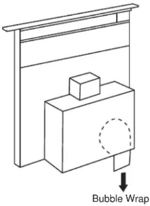
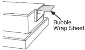
ATTENTION: Please remove the bubble wrap inserted inside of exhaust before installation. Make sure nothing is left inside the blower box.
READ AND SAVE THESE INSTRUCTIONS
Downdraft Vent System
To Use The Downdraft System
To raise the downdraft vent, press the button on the top cover. The vent will rise.
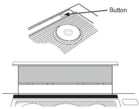
The blower can be turned ON or OFF and the speed can be adjusted with the recessed knob on the right side of the air vent. The blower, if left on, will automatically turn off when the vent is lowered.
NOTE: For most convenient operation, set the blower to the speed you use most often. The blower will come on to this speed whenever the unit is raised.
Lower the downdraft vent by pressing the button on the top cover. The vent will go down an the blower will shut off.
When Using The Vent System
▲CAUTION
Be careful when raising or lowering
the vent. Be sure pots, pot handles and other objects are clear of the vent and cannot be struck or tipped by the vent being raised.
NOTE: There is a slight trim overhang on each side of the vent.
■ To avoid injury, be sure fingers are clear of the vent cover when it is being lowered.
- Keep hands and fingers away from all vent parts.
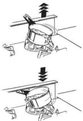
natural_image
Two-step diagram showing mechanical assembly with arrows indicating direction (no text or symbols)IMPORTANT: If the vent is obstructed by an object while it is being raised or lowered, it will stop. Carefully remove the obstruction and the vent will drop to the lowered position. Press the button again to return to normal functions.
Cooking Tips
The high air movement of this vent system can increase the cooking times for some foods. It may take longer to reach high cooking temperatures if the vent system is turned to high right away. Adjust the fan speed for best cooking results.
For best results when heating oil for deep frying or when boiling water, use the front surface units or wait until the water is boiling or the oil is at frying temperatures before turning on the vent system.
The vent system may not completely capture all the steam from pans on the front burners.
Downdraft Vent System
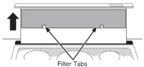
Grease Filters
The efficiency of your vent system depends on a clean filter. Frequency of cleaning depends on the type of cooking you do. Grease filters should be cleaned at least once a month. Never operate the vent system without the filters in place.
To remove: Remove filters from the air vent by reaching the filters through the vent openings, pushing down then pulling out. NOTE: The filters are different sizes. Be sure to replace them as removed, wider one on the left
To clean: Soak and then agitate in a hot detergent solution. Light brushing may be used to remove embedded soil. Rinse, shake and remove moisture before replacing. Do not clean the filters in the dishwasher.
With careful handling, the filter will last for years. If replacement becomes necessary, order the part from your dealer.
Painted Or Stainless Steel Surfaces
Do not use a steel wool pad; it will scratch the surface. To clean the stainless steel surface, use warm, sudsy water or a stainless steel cleaner or polish. Always wipe the surface in the direction of the grain. Follow the cleaner instructions for cleaning the stainless steel surface.
For difficult stains on stainless steel, use a cleaner that contains lactic acid or citric acid.
To inquire about purchasing cleaning products including stainless steel appliance cleaner or polish read the Assistance and Accessories sections at the beginning of this manual.
Installation Instructions
Downdraft Vent Systems
UVD6301S, UVD6361S
? "If you have questions, call GE Appliances at 800.GE.CARES (800.432.2737) or visit our website at: GEAppliances.com"
BEFORE YOU BEGIN
Read these instructions completely and carefully.
- IMPORTANT — Save these instructions for local inspector's use.
- IMPORTANT — Observe all governing codes and ordinances.
- Note to Installer – Be sure to leave these instructions with the Consumer.
- Note to Consumer – Keep these instructions for future reference.
- Skill level – Installation of this vent hood requires basic mechanical and electrical skills.
- Proper installation is the responsibility of the installer.
- Product failure due to improper installation is not covered under the Warranty.
GROUNDING INSTRUCTIONS
This appliance must be grounded. In the event of an electrical short circuit, grounding reduces the risk of electric shock by providing an escape wire for the electric current. This appliance is equipped with a cord having a grounding wire with a grounding plug. The plug must be plugged into an outlet that is property installed and grounded.
WARNING
Improper grounding can result in a risk of electric shock.
Consult a qualified electrician if the grounding instructions are not completely understood, or if doubt exist as to whether the appliance is properly grounded.
Do not use an extension cord. If the power supply cord is too short, have a qualified electrician install an outlet near the appliance.
If you received a damaged vent system, you should contact your dealer.
PARTS SUPPLIED
Open the carton and remove parts package. Check contents to be sure all pieces are present.

Filters - inside unit Qty:2
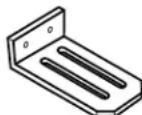
Stabilizing Brackets Qty:2
Countertop Mounting
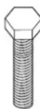
Screw, 1/4-20 x 2.00
Hex Hd
Qty:2

Downdraft
Leveling Screw,
1/4-20 x .50 Hex
Hd - Qty:2

Wood Screw, #8 x .750 SI Round Hd - Qty:4

TOOLS AND MATERIALS REQUIRED
- Safety glasses
• Large flat-blade screwdriver - Jigsaw
- Carpenter's square
- Ductwork to suit the installation
- Level
REMOVE PACKAGING
Remove the shipping materials and the carton; set carton aside. The carton can be used as a pad when changing or adjusting vent direction.
WARNING
TO REDUCE THE RISK OF FIRE, CK OR INJURY TO PERSONS, FOLLOWING:
- Installation work and electrical wiring must be done by qualified person(s) in accordance with all applicable codes and standards, including fire-rated construction.
- Sufficient air is needed for proper combustion and exhausting of gases through the flue (chimney) of fuel burning equipment to prevent back drafting. Follow the heating equipment manufacturer's guidelines and safety standards such as those published by the National Fire Protection Association (NFPA), the American Society for Heating, Refrigeration and Air Conditioning Engineers (ASHRAE) and the local code authorities.
- When cutting or drilling into wall or ceiling, do not damage electrical wiring and other hidden utilities.
- Ducted fans must always be vented to the outdoors.
CAUTION
TO REDUCE THE RISK OF FIRE
AND TO PROPERLY EXHAUST AIR, BE SURE TO DUCT AIR OUTDOORS. DO NOT VENT EXHAUST AIR INTO SPACES WITHIN WALLS OR CEILINGS OR INTO ATTICS, CRAWL SPACES OR GARAGES.
⚠ WARNING
TO REDUCE THE RISK OF FIRE, AL DUCT WORK.
- When applicable, install any makeup (replacement) air system in accordance with local building code requirements. Visit GEAppliances.com for available makeup air solutions.
- PVC sewer pipe can be used as duct under concrete slab if allowed by local code board.
POWER SUPPLY
This downdraft vent must be supplied with 120V, 60 Hz. and connected to an individual, properly grounded branch circuit, protected by a 15- or 20-ampere circuit breaker or time-delay fuse.
A properly grounded 3-prong receptacle should be located within reach of the vent's two-foot power cord.
- Gas Cooktops
If this vent is installed in combination with a GE or Monogram gas cooktop, it may operate from the same duplex outlet.
• Electric Cooktops
If this vent is installed in combination with a GE or Monogram electric cooktop, the vent must operate from a separate 120V outlet.
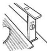
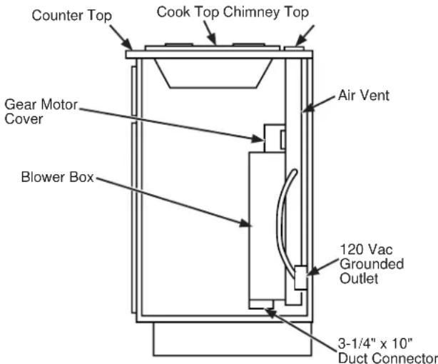
Locate the receptacle inside the cabinet on the right side wall (see illustration). The receptacle cannot be placed on the back of the cabinet wall where it may interfere with the downdraft plenum.
The downdraft vent power cord is to be routed beneath the cooktop and routed away from heat generated by the cooktop.
Ensure that the cooktop is installed per manufacturer's installation instructions.
SPECIFICATIONS
| VOLTS | AMPS | DUCT |
| 120 4.0 | 3-1/4 X | 10 |

IMPORTANT
(Please read carefully)
The power cord of this appliance is equipped with a three-prong (grounding) plug which mates with a standard three-prong grounding wall receptacle to minimize the possibility of electric shock. The customer should have the wall receptacle and circuit checked by a qualified electrician to make sure the receptacle is properly grounded and has correct polarity.
- Where a standard two-prong wall receptacle is encountered, it is the personal responsibility and obligation of the customer to have it replaced with a properly grounded three-prong wall receptacle.
Do not, under any circumstances, cut or remove the third (ground) prong from the power cord.
Do not use an extension cord or adapter plug with this appliance. Follow National Electrical Code or prevailing local codes and ordinances.
Location of Rating Label: on front of chassis of vent system.
Installation Preparation
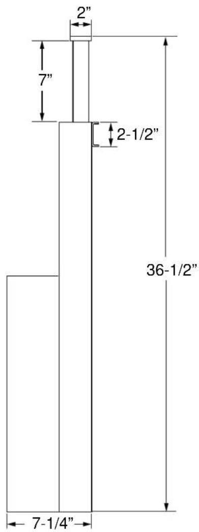
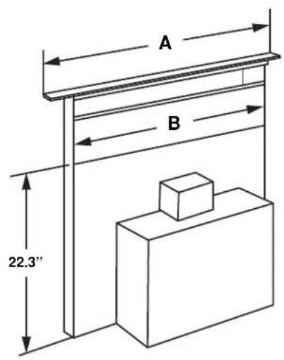
PRODUCT DIMENSIONS
| A | B | |
| 30" Models 30" 26-1/4" | ||
| 36" Models 36" 32-1/4" |

PREPARING FOR INSTALLATION
- Unpack the cooktop and read the Installation Instructions to understand the required countertop cutout dimensions and location in the countertop, the cooktop spacing to the front edge of the countertop, and the required clearances to the cabinets and walls. The vent system required cutout width is shown on page 9. Confirm there is enough side to side counter space to meet the required spacing and clearances for the cooktop.
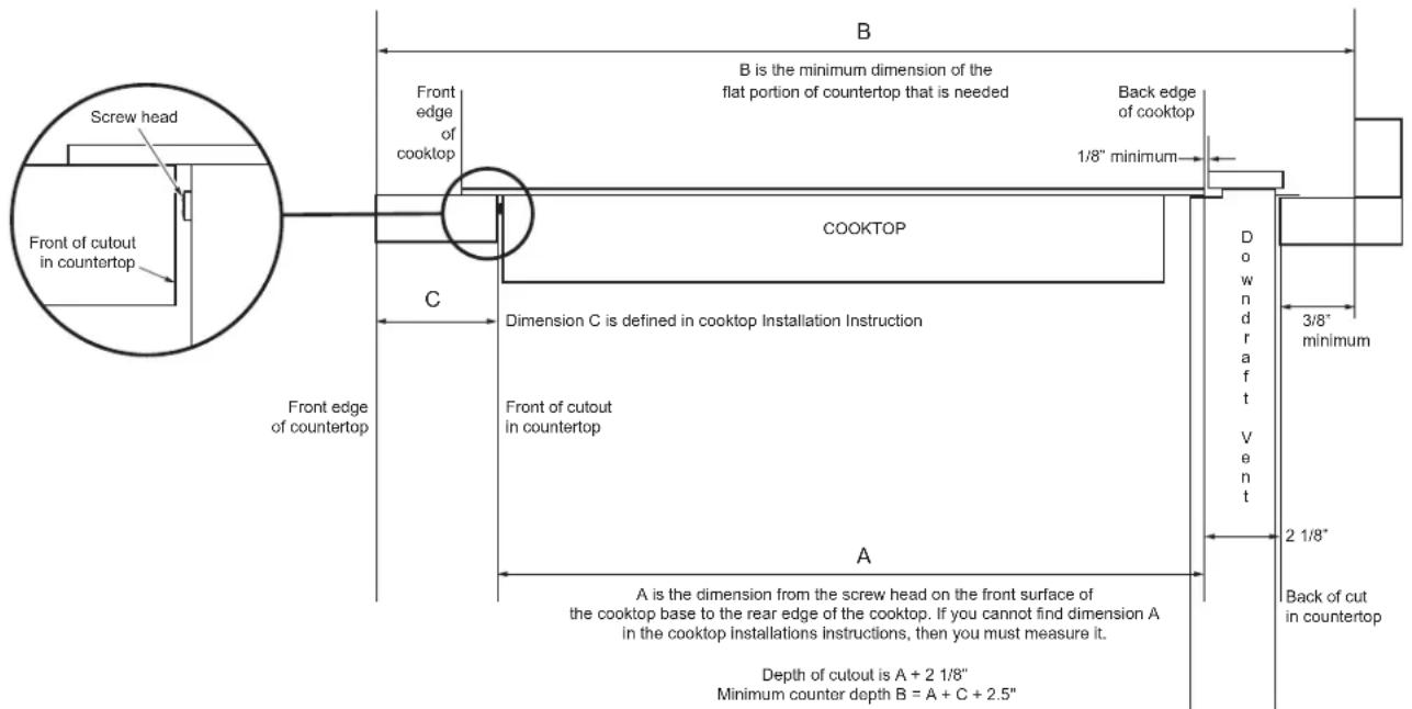
- Using the illustrations below and taking measurements of the cooktop to establish dimension A, confirm there is enough front to back counter space (dimension B) to fit both the cooktop and the vent system. Note the cooktop rear edge will overlap the vent system front surface (refer to Page 10).
• Refer to the Creative Solutions section on page 13 if more counter space is needed.
- Using the illustrations on pages 9 through 12 and taking measurements of the vent system and its exhaust vent location, confirm the clearances needed within the cabinet, the exhaust vent direction, and the alignment of the exhaust vent with the ducting. If needed for clearance or duct hookup alignment, reposition the location of the cooktop, or modify the cabinetry, or modify the ducting.
- Confirm the electrical receptacles and gas lines are correctly located, and relocate if needed.
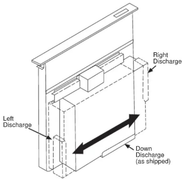
VENTING OPTIONS
- The downdraft vent is shipped with the discharge outlet pointing straight down and can be changed to the left or right side. To avoid interference problems, the downdraft vent cannot be vented to the right when installed with a GE or Monogram gas cooktop, or with a GE or Monogram non-induction electric cooktop.
- The blower outlet is sized for 3-1/4" x 10" and can be transitioned to 6" round.
The blower is shipped with its discharge facing DOWN. Follow these steps ONLY if:
- the position of the blower discharge needs to be moved so ductwork does not interfere with floor joists, plumbing or wiring below.
- it is necessary to rotate the blower discharge to the RIGHT or LEFT.
Place the unit on its back on a table or work surface.
Pull out the bubble wrap sheet. Make sure nothing is left inside.
- Loosen the 4 nuts and 2 clamp channels.
- Remove the 5 screws on the bottom. These 5 screws are for shipping and do not need to be re-tightened.
- Slide blower to desired position.
- Use supplied cover plate to close open space (if any).
- Tighten wing nuts to secure top of blower and use sheet metal screws through bottom flange to secure bottom of blower.
LEFT OR RIGHT DISCHARGE
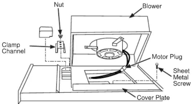
- Remove the 4 nuts and 2 clamp channels.
- Remove the 5 screws on the bottom. These 5 screws are for shipping and do not need to be re-tightened.
- Carefully lift blower and disconnect motor plug if necessary. Reposition blower and RECONNECT MOTOR PLUG.
- Use supplied cover plate to close open space (if any).
- Replace clamp channels and use nuts to secure the blower in its new position.
- Use sheet metal screws through bottom flange to secure bottom of blower.
For best performance: Choose the ducting option which allows the shortest length of ductwork and a minimum number of elbows and transitions. Check location of floor joists, wall studs, electrical wiring or plumbing for possible interference.
NOTE: The unit is shipped with the 3-1/4" x 10" discharge facing DOWN. See "CHANGING BLOWER DIRECTION" on page 3, if necessary.
The system will operate most efficiently when the ductwork does not exceed 40 feet of equivalent duct.
The chart, below, shows equivalent feet of elbows and transitions. The number of feet of straight duct plus the equivalent feet of transitions and/or elbows to be used should equal 40 feet or less.
| 6" Round Elbow | 3-1/4"x10" to 6" Round Transition | 3-1/4"x10" 90° Elbow |
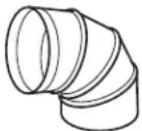 |  | 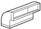 |
| equals 6 ft. of straight duct | equals 2 ft. of straight duct | equals 8 ft. of straight duct |
CREATIVE SOLUTIONS
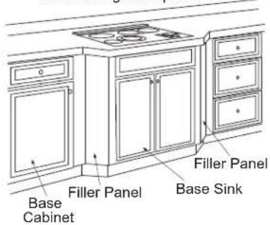
- When the kitchen design calls for an against-the-wall installation, move the base cabinet forward 3" to 5". Filler panels or complementary moldings can be added to exposed cabinet sides.
- In an island or peninsula, use an extra-deep countertop. The countertop overhang at the front can be adjusted to meet setback to cutout requirements.
- When the cutout to the front edge of the countertop requirement is more than 2", add a bullnose trim to the front edge of the countertop. Include the trim thickness when measuring the front edge to cutout requirement. By adding the trim, the cooktop can be moved forward,
Maintain Cutout Clearances to Front Edge as Specified

providing additional countertop depth and interior cabinet space.

- When the distances between the vent and the inside cabinet side walls are more than 5-1/2" and/or the inside cabinet back wall is more than 4-1/2", false walls should be constructed inside the cabinet for securing the vent with the stabilizing brackets (refer to Cutouts and Clearances under Installation Preparation.)

natural_image
Simple line drawing of a two-weeked table with a central square and two side supports (no text or symbols)PREPARING THE COUNTERTOP
Lay out and cut the cooktop cut-out far enough FORWARD so downdraft will fit behind it.
- Set cooktop in place and slide it as far forward as possible. Center and square it with edges or countertop.
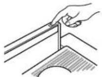
- Place the plastic template against the back flange of the cooktop and center it. Trace around template to mark the downdraft opening.
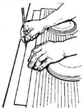
natural_image
Illustration of hands using a pen and ruler to cut or mark a wooden plank (no text or symbols)- Remove cooktop from countertop.
- Cut downdraft opening. Be careful not to chip edges of countertop.
PREPARE FOR DUCTWORK
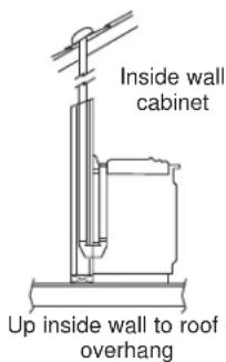
Determine the best route for ductwork; it can be routed in a variety of ways depending on the kitchen layout.
IMPORTANT: The downdraft air discharge outlet for this unit is 31/4" x 10" rectangular. Plan ducting accordingly.
Typical duct arrangement countertop series.
To maximize the ventilation performance of the vent system:
- Minimize the duct run length and number of transitions and elbows.
- Maintain a constant duct size.
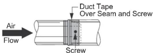
- Seal all joints with duct tape to prevent any leaks.
- Do not use any type of flexible ducting.
Optional duct arrangement under concrete slab. PVC duct should be used if installing under a poured concrete slab.
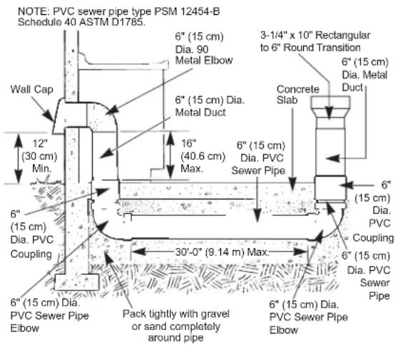


Install ductwork so the piece of duct nearest the downdraft unit slots INTO the next piece of the duct. Secure the joints with self-tapping screws and apply duct tape around the joints to ensure an airtight seal.
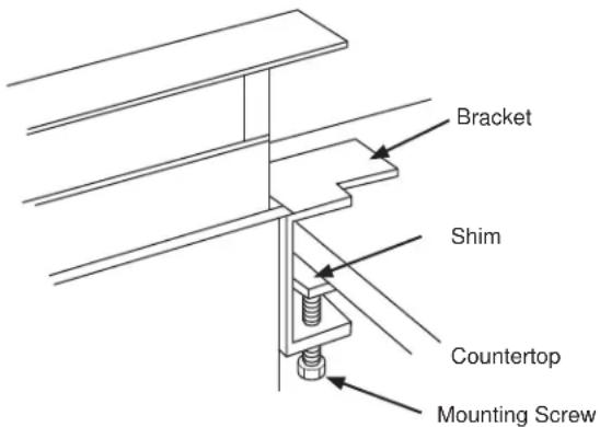
1 MOUNT THE UNIT
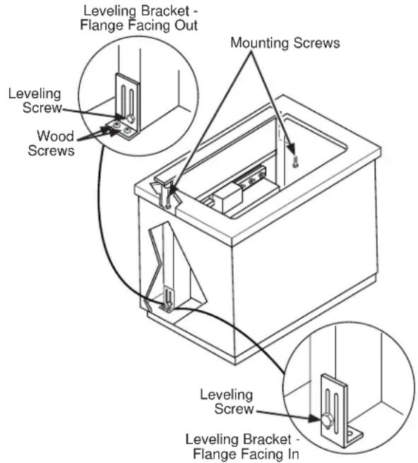
A Set downdraft into opening. Extend leveling brackets to floor of cabinet so downdraft sits straight. (NOTE: Leveling brackets can be removed and re-attached in other positions. Bottom flange may have to face inward in tight cabinet installations.)
B Secure the downdraft to the countertop as follows: Hold the downdraft against the back of countertop cut-out and tighten the 2 mounting screws (one on each end of unit) on underside of countertop. Use a shim between screw and underside of granite countertops.
The ends of the template may be broken or cut and used as shims if required.

Break/Cut the Ends
1 MOUNT THE UNIT (Cont.)
C Screw leveling brackets to bottom of cabinet using the four wood screws (provided with the unit) on each side.
D Tighten leveling screws through leveling bracket slots to the unit on each side.
E Place cooktop into the countertop cutout. There should be 1/8" minimum gap between the front of the vent trim and the rear of the cooktop.
F Connect duct. Use a roof or wall cap (with damper) that is intended for use with kitchen hoods and vent systems.
2 CONNECT POWER
Plug power cord into properly grounded receptacle.
3 INSTALL FILTERS, CHECK OPERATION
- Press the button on the top cover to raise the vent.
- Lift the vent straight up and pull forward.
- Slide filter into the retainers and close the vent.
- Turn the knob on the right side of the air vent to start the blower and adjust the speed.
- To lower the vent, press the button on the top cover.
NOTE: It is not necessary to turn the fan OFF before lowering the vent. The fan will automatically turn off when the vent is lowered. When the fan is not turned off before lowering the vent, it will automatically come on at the previously set speed when the vent is fully raised.
TROUBLESHOOTING TIPS
Save time and money! Review the charts on the following pages first and you may not need to call for service.
| Problem Possible Cause What To Do | ||
| Fan does not work The vent is not fully extended. Press the button on the top cover. | ||
| Vent does not work | The vent is not plugged into an outlet. | Plug the vent into a 120V power outlet. |
| The button did not engage the lift motor. | Hold down the button for a couple of seconds to activate the motor. | |
| The circuit breaker may have tripped. | Check the circuit breaker—reset if necessary. | |
| Sufficient makeup (replacement) air is required for exhausting appliances to operate to rating. | Check with local building codes, which may require or strongly advise the use of makeup air. Visit GEAppliances.com for available makeup air solutions. | |
GE Appliances Limited Warranty
GEAppliances.com
All warranty service is provided by our Factory Service Centers, or an authorized Customer Care® technician. To schedule service online, visit us at GEAppliances.com/service, or call GE Appliances at 800.GE.CARES (800.432.2737). Please have your serial number and your model number available when calling for service.
Servicing your appliance may require the use of the onboard data port for diagnostics. This gives a GE Appliances factory service technician the ability to quickly diagnose any issues with your appliance and helps GE Appliances improve its products by providing GE Appliances with information on your appliance. If you do not want your appliance data to be sent to GE Appliances, please advise your technician not to submit the data to GE Appliances at the time of service.
| For the period of GE Appliances will replace | |
| One yearFrom the dateof the originalpurchase | Any part of the cooking product which fails due to a defect in materials or workmanship.During this limited one-year warranty, GE Appliances will provide, free of charge, all laborand related service costs to replace the defective part. |
What GE Appliances will not cover:
■ Service trips to your home to teach you how to use the product.
■ Improper installation, delivery, or maintenance.
■ Failure of the product if it is abused, misused, modified, or used for other than the intended purpose or used commercially.
■ Replacement of house fuses or resetting of circuit breakers.
■ Damage to the product caused by accident, fire, floods, or acts of God.
■ Incidental or consequential damage caused by possible defects with this appliance.
■ Damage caused after delivery.
■ Product not accessible to provide required service.
■ Service to repair or replace light bulbs, except for LED lamps.
EXCLUSION OF IMPLIED WARRANTIES
Your sole and exclusive remedy is product repair as provided in this Limited Warranty. Any implied warranties, including the implied warranties of merchantability or fitness for a particular purpose, are limited to one year or the shortest period allowed by law.
This limited warranty is extended to the original purchaser and any succeeding owner for products purchased for home use within the USA. If the product is located in an area where service by a GE Appliances Authorized Servicer is not available, you may be responsible for a trip charge or you may be required to bring the product to an Authorized GE Appliances Service location for service. In Alaska, the limited warranty excludes the cost of shipping or service calls to your home.
Some states do not allow the exclusion or limitation of incidental or consequential damages. This limited warranty gives you specific legal rights, and you may also have other rights which vary from state to state. To know what your legal rights are, consult your local or state consumer affairs office or your state's Attorney General.
Warrantor: GE Appliances, a Haier company
Louisville, KY 40225
Extended Warranties: Purchase a GE Appliances extended warranty and learn about special discounts that are available while your warranty is still in effect. You can purchase it online anytime at
GEAppliances.com/extended-warranty
or call 800.626.2224 during normal business hours. GE Appliances Service will still be there after your warranty expires.
If you received a damaged downdraft vent system
Immediately contact the dealer (or builder) that sold you the downdraft vent system.
Accessories
Looking For Something More?
GE Appliances offers a variety of accessories to improve your cooking and maintenance experiences!
Refer to the Consumer Support page for phone numbers and website information.
The following products and more are available:
Parts
Black Stainless Steel Trim (30")
Black Stainless Steel Trim (36")
Cleaning Supplies
CitruShine™ Stainless Steel Wipes
Stainless Steel Appliance Cleaner
Consumer Support
GE Appliances Website
Have a question or need assistance with your appliance? Try the GE Appliances Website 24 hours a day, any day of the year! You can also shop for more great GE Appliances products and take advantage of all our on-line support services designed for your convenience. In the US: GEAppliances.com
Register Your Appliance
Register your new appliance on-line at your convenience! Timely product registration will allow for enhanced communication and prompt service under the terms of your warranty, should the need arise. You may also mail in the pre-printed registration card included in the packing material. In the US: GEAppliances.com/register
Schedule Service
Expert GE Appliances repair service is only one step away from your door. Get on-line and schedule your service at your convenience any day of the year. In the US: GEAppliances.com/service or call 800.432.2737 during normal business hours.
Extended Warranties
Purchase a GE Appliances extended warranty and learn about special discounts that are available while your warranty is still in effect. You can purchase it on-line anytime. GE Appliances Services will still be there after your warranty expires. In the US: GEAppliances.com/extended-warranty or call 800.626.2224 during normal business hours.
Remote Connectivity
For assistance with wireless network connectivity (for models with remote enable), visit our website at GEAppliances.com/connect or call 800.220.6899 in the US.
Parts and Accessories
Individuals qualified to service their own appliances can have parts or accessories sent directly to their homes (VISA, MasterCard and Discover cards are accepted). Order on-line today 24 hours every day. In the US: GEApplianceparts.com or by phone at 877.959.8688 during normal business hours.
Instructions contained in this manual cover procedures to be performed by any user. Other servicing generally should be referred to qualified service personnel. Caution must be exercised, since improper servicing may cause unsafe operation.
Contact Us
If you are not satisfied with the service you receive from GE Appliances, contact us on our Website with all the details including your phone number, or write to:
In the US: General Manager, Customer Relations | GE Appliances, Appliance Park | Louisville, KY 40225 GEAppliances.com/contact
natural_image
Simple line drawing of a windmill with an upward arrow and ground lines (no text or symbols)
natural_image
Diagram of a mechanical assembly with a downward arrow indicating force or direction (no text or symbols present)DIMENSIONES DEL PRODUCTO
| A | B | |
| 30" Modelos 30" 26 | 1/4" | |
| 36" Modelos 36" 32 | 1/4" |

natural_image
Simple line drawing of a table with a square and two vertical supports (no text or symbols)natural_image
Illustration of hands using a ruler and pen to cut or mark a rectangular object (no text or symbols visible)Louisville, KY 40225
GEAppliances.com/extended-warranty
- OWNER'S MANUAL & INSTALLATION INSTRUCTIONS
- THANK YOU FOR MAKING GE APPLIANCES A PART OF YOUR HOME.
- IMPORTANT SAFETY INFORMATION READ ALL INSTRUCTIONS BEFORE USING
- WARNING
- CAUTION
- If You Need Service...
- READ AND SAVE THESE INSTRUCTIONS
- How to Remove Protective Shipping Film and Packaging Tape
- Downdraft Vent System
- To Use The Downdraft System
- When Using The Vent System
- ▲CAUTION
- Cooking Tips
- Grease Filters
- Painted Or Stainless Steel Surfaces
- Installation Instructions
- Downdraft Vent Systems
- UVD6301S, UVD6361S
- BEFORE YOU BEGIN
- GROUNDING INSTRUCTIONS
- PARTS SUPPLIED
- TOOLS AND MATERIALS REQUIRED
- REMOVE PACKAGING
- ⚠ WARNING
- POWER SUPPLY
- - Gas Cooktops
- • Electric Cooktops
- IMPORTANT
- (Please read carefully)
- Do not, under any circumstances, cut or remove the third (ground) prong from the power cord.
- Installation Preparation
- PREPARING FOR INSTALLATION
- VENTING OPTIONS
- CREATIVE SOLUTIONS
- PREPARING THE COUNTERTOP
- PREPARE FOR DUCTWORK
- TROUBLESHOOTING TIPS
- GE Appliances Limited Warranty
- GEAppliances.com
- What GE Appliances will not cover:
- EXCLUSION OF IMPLIED WARRANTIES
- If you received a damaged downdraft vent system
- Accessories
- Looking For Something More?
- Parts
- Cleaning Supplies
- Consumer Support
- GE Appliances Website
- Register Your Appliance
- Schedule Service
- Extended Warranties
- Remote Connectivity
- Parts and Accessories
- Contact Us
Brand : Monogram
Model : UVD6301SPSS
Category : Range hood