
DTW281RMJ - Drill driver MAKITA - Free user manual and instructions
Find the device manual for free DTW281RMJ MAKITA in PDF.


| Product Type | Cordless Impact Wrench |
| Brand | Makita |
| Model | DTW281RMJ |
| Rated Voltage | 18 V DC |
| Screw Capacities | Standard bolt: M10 - M20 High-strength bolt: M10 - M16 |
| Drive Square | 12.7 mm |
| No-load speed (hard mode) | 0 - 2,800 min⁻¹ |
| No-load speed (medium mode) | 0 - 2,100 min⁻¹ |
| No-load speed (soft mode) | 0 - 1,600 min⁻¹ |
| Impacts per minute (hard mode) | 0 - 3,500 min⁻¹ |
| Impacts per minute (medium mode) | 0 - 2,600 min⁻¹ |
| Impacts per minute (soft mode) | 0 - 1,800 min⁻¹ |
| Total length | 147 mm |
| Net weight (with battery EPTA) | 1.7 kg |
| Power source | Lithium-ion battery 18 V (not included) |
| Impact force adjustment | 3 levels: hard, medium, soft |
| Lighting | Front LED lamp with on/off |
| Battery charge indicator | LED display on battery |
| Rotation direction | Reversing switch with neutral position |
| Suspension hook | Yes, reversible |
| Safety | Battery protection circuit, trigger lock in neutral position |
| Maintenance | Clean with a dry cloth; repairs by Makita authorized service center |
| Included accessories | Hook, socket (depending on version) |
| Sound level (pressure) | 96 dB(A) |
| Vibration level (impact tightening) | 11.5 m/s² (uncertainty K=1.5 m/s²) |
Frequently Asked Questions - DTW281RMJ MAKITA
User questions about DTW281RMJ MAKITA
0 question about this device. Answer the ones you know or ask your own.
Ask a new question about this device
Download the instructions for your Drill driver in PDF format for free! Find your manual DTW281RMJ - MAKITA and take your electronic device back in hand. On this page are published all the documents necessary for the use of your device. DTW281RMJ by MAKITA.
USER MANUAL DTW281RMJ MAKITA
GB Cordless Impact Wrench Instruction Manual
natural_image
Line drawing of a handheld electric drill putter with no text or symbols
1
2
3
4
5
6
7
014641
flowchart
graph TD
    A["Stage 9: 1s D"] --> B["Stage 10: S/H"]
    B --> C["Stage 11: 1s D"]
    C --> D["Stage 12: S/H"]
    D --> E["Output: 1s D"]
    style A fill:#f9f,stroke:#333
    style B fill:#ccf,stroke:#333
    style C fill:#cfc,stroke:#333
    style D fill:#fcc,stroke:#333
    style E fill:#ffc,stroke:#333
014644
8
9
10
014637014643
11 12
natural_image
Line drawing of a hand using a handheld power tool to press or install a cylindrical component (no text or symbols)014638
014822
line
| Series | Value | |--------|-------| | M12 | 40 | | M16 | 80 | | M20 | 200 |13 14
line
| Series | Value | |--------|-------| | M12H | 120 | | M14H | 160 | | M16H | 240 | | M16H | 280 |014823
014824
line
| Time (s) | M12 (N·m) | M16 (N·m) | M20 (N·m) | M23 (N·m) | | -------- | --------- | --------- | --------- | --------- | | 0 | 0 | 0 | 0 | 0 | | 0.5 | ~80 | ~120 | ~160 | ~180 | | 1.0 | ~120 | ~160 | ~200 | ~200 | | 1.5 | ~160 | ~200 | ~200 | ~200 | | 2.0 | ~200 | ~200 | ~200 | ~200 |15 16
line
| Time (s) | M12H (N·m) | M12H (N·m) | M14H (N·m) | M14H (N·m) | M16H (N·m) | | -------- | ---------- | ---------- | ---------- | ---------- | ---------- | | 0 | 0 | 0 | 0 | 0 | 0 | | 1.0 | ~120 | ~160 | ~180 | ~200 | ~240 | | 2.0 | ~160 | ~200 | ~220 | ~240 | ~260 | | 3.0 | ~200 | ~240 | ~260 | ~280 | ~280 |014825
014826
ENGLISH (Original instructions)
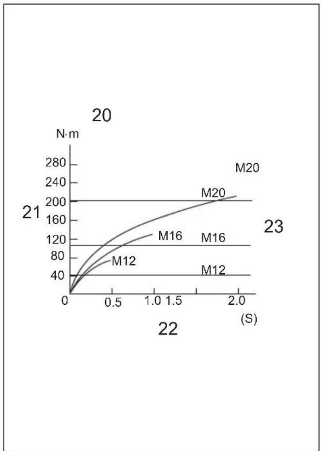
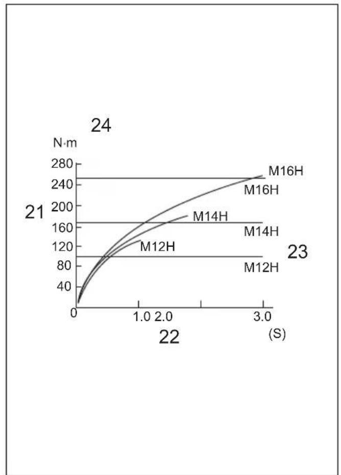
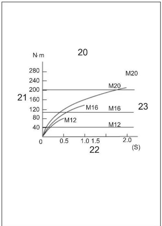
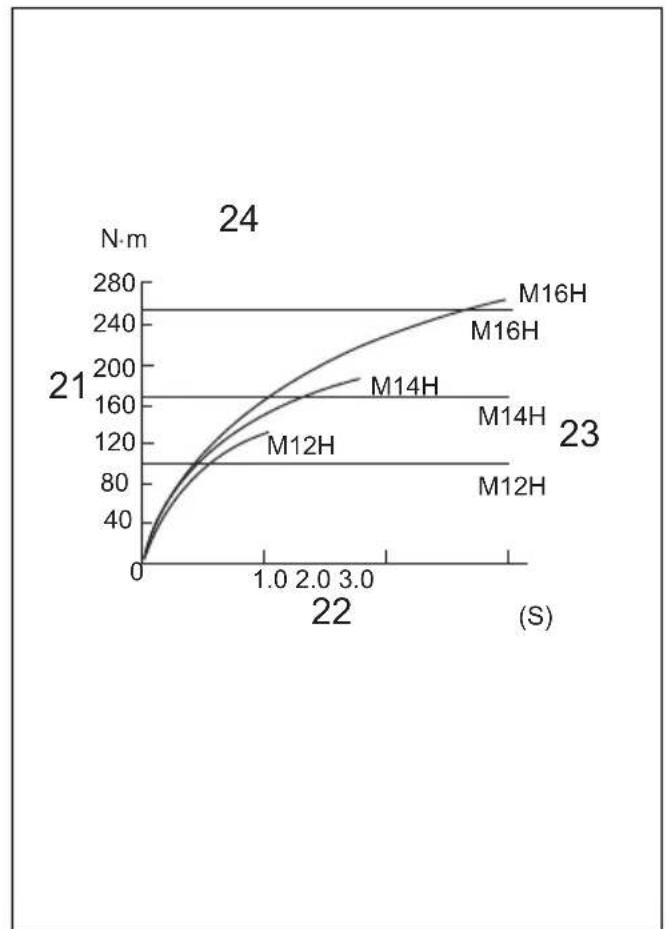
| Explanation of general view | ||
| 1 Red indicator | 10 Hard | 19 Groove |
| 2 Button | 11 Medium | 20 Standard bolt |
| 3 Battery cartridge | 12 Soft | 21 Fastening torque |
| 4 Star marking | 13 Socket | 22 Fastening time |
| 5 LED display | 14 Square drive | 23 Proper fastening torque |
| 6 Switch trigger | 15 O-ring | 24 High tensile bolt |
| 7 Lamp | 16 Pin | |
| 8 Reversing switch lever | 17 Hook | |
| 9 Changed in three steps | 18 Screw | |
SPECIFICATIONS
| Model DTW280 DTW281 | |||
| Capacities | Standard bolt | M10 – M20 | M10 – M20 |
| High tensile bolt | M10 – M16 | M10 – M16 | |
| Square drive 12.7 mm 12.7 mm | |||
| No load speed (min ^-1 ) | Impact mode (Hard) | 0 – 2,800 | 0 – 2,800 |
| Impact mode (Medium) | 0 – 2,100 | 0 – 2,100 | |
| Impact mode (Soft) | 0 – 1,600 | 0 – 1,600 | |
| Impacts per minute (min ^-1 ) | Impact mode (Hard) | 0 – 3,500 | 0 – 3,500 |
| Impact mode (Medium) | 0 – 2,600 | 0 – 2,600 | |
| Impact mode (Soft) | 0 – 1,800 | 0 – 1,800 | |
| Overall length | 147 mm | 147 mm | |
| Net weight | 1.5 kg | 1.7 kg | |
| Rated voltage | D.C. 14.4 V | D.C. 18 V | |
- Due to our continuing program of research and development, the specifications herein are subject to change without notice.
- Specifications and battery cartridge may differ from country to country.
- Weight, with battery cartridge, according to EPTA-Procedure 01/2003
ENE036-1
Intended use
The tool is intended for fastening bolts and nuts.
GEA010-1
General Power Tool Safety Warnings
⚠ WARNING Read all safety warnings and all instructions. Failure to follow the warnings and instructions may result in electric shock, fire and/or serious injury.
Save all warnings and instructions for future reference.
GEB049-2
CORDLESS IMPACT WRENCH SAFETY WARNINGS
- Hold power tool by insulated gripping surfaces, when performing an operation where the fastener may contact hidden wiring. Fasteners contacting a "live" wire may make exposed metal parts of the power tool "live" and could give the operator an electric shock.
- Wear ear protectors.
- Check the socket carefully for wear, cracks or damage before installation.
- Hold the tool firmly.
- Always be sure you have a firm footing. Be sure no one is below when using the tool in high locations.
- The proper fastening torque may differ depending upon the kind or size of the bolt. Check the torque with a torque wrench.
SAVE THESE INSTRUCTIONS.
WARNING:
DO NOT let comfort or familiarity with product (gained from repeated use) replace strict adherence to safety rules for the subject product.
MISUSE or failure to follow the safety rules stated in this instruction manual may cause serious personal injury.
IMPORTANT SAFETY INSTRUCTIONS
FOR BATTERY CARTRIDGE
- Before using battery cartridge, read all instructions and cautionary markings on (1) battery charger, (2) battery, and (3) product using battery.
- Do not disassemble battery cartridge.
- If operating time has become excessively shorter, stop operating immediately. It may result in a risk of overheating, possible burns and even an explosion.
- If electrolyte gets into your eyes, rinse them out with clear water and seek medical attention right away. It may result in loss of your eyesight.
- Do not short the battery cartridge:
(1) Do not touch the terminals with any conductive material.
(2) Avoid storing battery cartridge in a container with other metal objects such as nails, coins, etc.
(3) Do not expose battery cartridge to water or rain.
A battery short can cause a large current flow, overheating, possible burns and even a breakdown.
- Do not store the tool and battery cartridge in locations where the temperature may reach or exceed 50°C (122°F).
- Do not incinerate the battery cartridge even if it is severely damaged or is completely worn out. The battery cartridge can explode in a fire.
- Be careful not to drop or strike battery.
- Do not use a damaged battery.
- Follow your local regulations relating to disposal of battery.
SAVE THESE INSTRUCTIONS.
Tips for maintaining maximum battery life
- Charge the battery cartridge before completely discharged. Always stop tool operation and charge the battery cartridge when you notice less tool power.
- Never recharge a fully charged battery cartridge. Overcharging shortens the battery service life.
- Charge the battery cartridge with room temperature at 10^ C – 40^ C ( 50^ F – 104^ F). Let a hot battery cartridge cool down before charging it.
- Charge the battery cartridge once in every six months if you do not use it for a long period of time.
FUNCTIONAL DESCRIPTION

CAUTION:
- Always be sure that the tool is switched off and the battery cartridge is removed before adjusting or checking function on the tool.
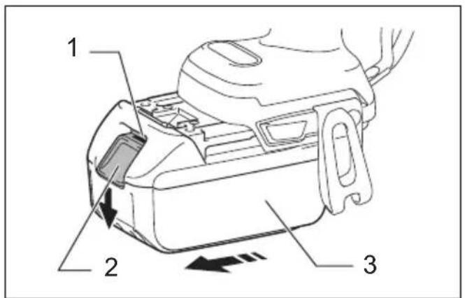
Installing or removing battery cartridge (Fig. 1)

CAUTION:
- Always switch off the tool before installing or removing of the battery cartridge.
- Hold the tool and the battery cartridge firmly when installing or removing battery cartridge. Failure to hold the tool and the battery cartridge firmly may cause them to slip off your hands and result in damage to the tool and battery cartridge and a personal injury.
To remove the battery cartridge, slide it from the tool while sliding the button on the front of the cartridge.
To install the battery cartridge, align the tongue on the battery cartridge with the groove in the housing and slip it into place. Insert it all the way until it locks in place with a little click. If you can see the red indicator on the upper side of the button, it is not locked completely.

CAUTION:
- Always install the battery cartridge fully until the red indicator cannot be seen. If not, it may accidentally fall out of the tool, causing injury to you or someone around you.
- Do not install the battery cartridge forcibly. If the cartridge does not slide in easily, it is not being inserted correctly.
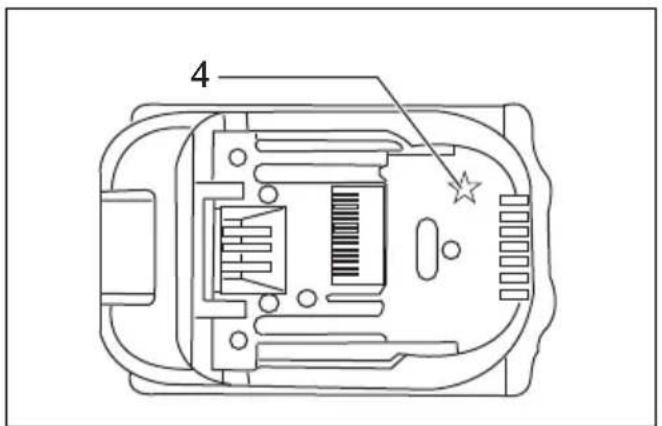
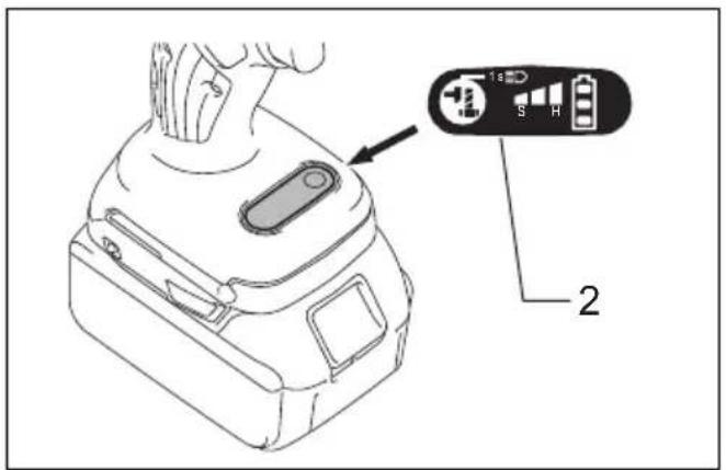
Battery protection system (Lithium-ion battery with star marking) (Fig. 2)
Lithium-ion batteries with a star marking are equipped with a protection system. This system automatically cuts off power to the tool to extend battery life.
The tool will automatically stop during operation if the tool and/or battery are placed under one of the following conditions:
- Overloaded:
The tool is operated in a manner that causes it to draw an abnormally high current.
In this situation, release the trigger switch on the tool and stop the application that caused the tool to become overloaded. Then pull the trigger switch again to restart.
If the tool does not start, the battery is overheated. In this situation, let the battery cool before pulling the trigger switch again.
- Low battery voltage:
The remaining battery capacity is too low and the tool will not operate. In this situation, remove and recharge the battery.
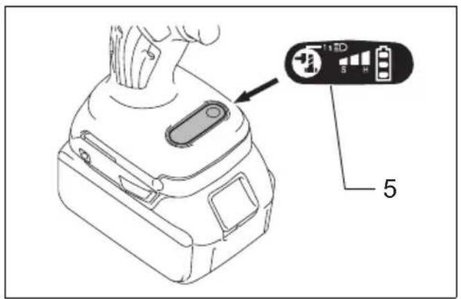
Indicating the remaining battery capacity (Fig. 3)
When you pull the switch trigger, the LED display shows the remaining battery capacity.
The remaining battery capacity is shown as the following table.
| LED indicator status Remaining battery capacity | |
| [1982T] | About 50% or more |
 | About 20% – 50% |
| [Y6GS] | About less than 20% |
012273
NOTE:
- When the LED display goes off, the tool is turned off to save the battery power. To check the remaining battery capacity, slightly pull the switch trigger.
- The LED display goes off approximately one minute after releasing the switch trigger.
- When the tool is overheated, the light flashes for one minute, and then the LED display goes off. In this case, cool down the tool before operating again.
- When the LED display lights up and the tool stops even with a recharged battery cartridge, cool down the tool fully. If the status will not change, stop using and have the tool repaired by a Makita local service center.
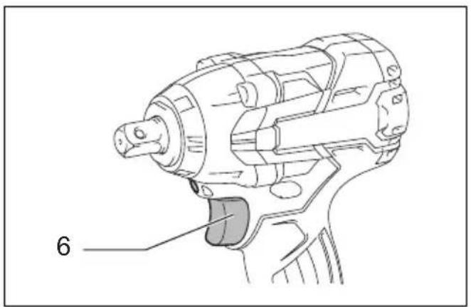
Switch action (Fig. 4)

CAUTION:
- Before installing the battery cartridge into the tool, always check to see that the switch trigger actuates properly and returns to the "OFF" position when released.
To start the tool, simply pull the switch trigger. Tool speed is increased by increasing pressure on the switch trigger. Release the switch trigger to stop.
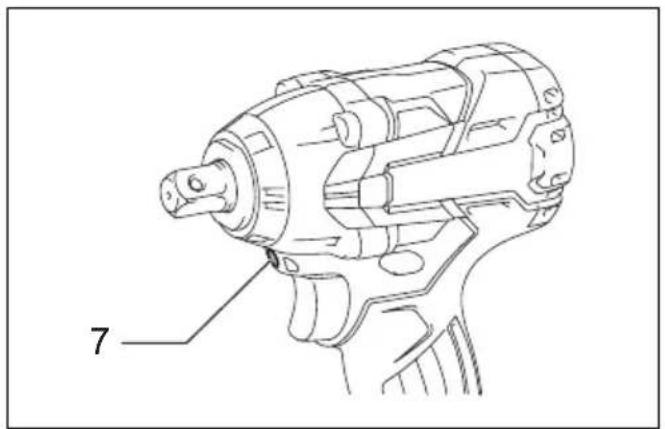
Lighting up the front lamp (Fig. 5 & 6)

CAUTION:
- Do not look in the light or see the source of light directly.
To turn on the lamp status, press the button for one second. To turn off the lamp status, press the button for one second again.
With the lamp status ON, pull the switch trigger to turn on the lamp. To turn off, release it. The lamp goes out approximately 10 seconds after releasing the switch trigger.
With the lamp status OFF, the lamp does not turn on even if pulling the trigger.
NOTE:
- To confirm the lamp status, pull the trigger. When the lamp lights up by pulling the switch trigger, the lamp status is ON. When the lamp does not come on, the lamp status is OFF.
- Use a dry cloth to wipe the dirt off the lens of lamp. Be careful not to scratch the lens of lamp, or it may lower the illumination.
- While pulling the switch trigger, the lamp status cannot be changed.
- For approximately 10 seconds after releasing the switch trigger, the lamp status can be changed.
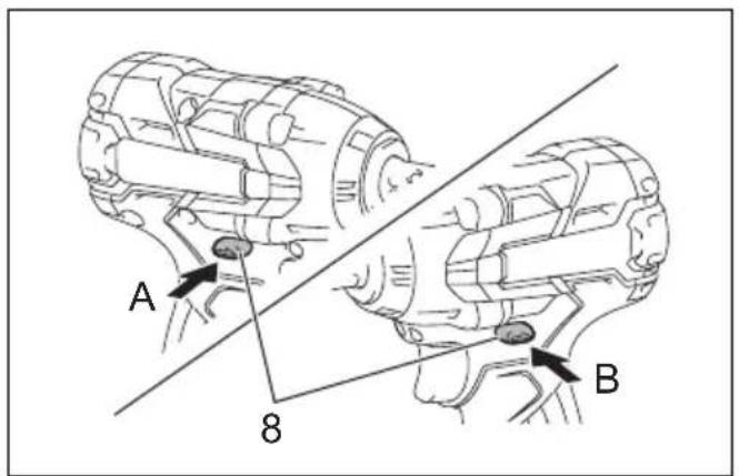
Reversing switch action (Fig. 7)

CAUTION:
- Always check the direction of rotation before operation.
- Use the reversing switch only after the tool comes to a complete stop. Changing the direction of rotation before the tool stops may damage the tool.
- When not operating the tool, always set the reversing switch lever to the neutral position.
This tool has a reversing switch to change the direction of rotation. Depress the reversing switch lever from the A side for clockwise rotation or from the B side for counterclockwise rotation.
When the reversing switch lever is in the neutral position, the switch trigger cannot be pulled.
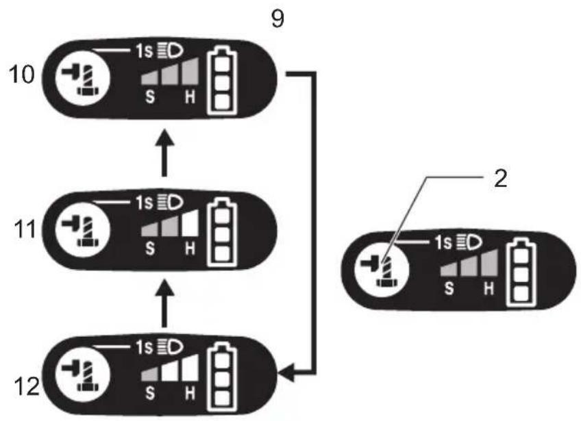
Changing the impact force (Fig. 8)
| Impact force grade displayed on panel | Maximum blows Application Work | |
Hard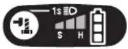 | 3,500 (min ^-1 ) | Tightening when force and speed are desired. |
Medium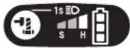 | 2,600 (min ^-1 ) | Tightening when you need good controlled power. |
Soft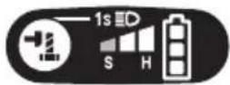 | 1,800 (min ^-1 ) | Tightening when you need fine adjustment with small diameter bolt. |
014829
You can change the impact in three steps: hard, medium and soft mode.
This allows a tightening suitable to the work.
Every time the button is pressed, the number of blows changes in three steps.
For approximately one minute after releasing the switch trigger, the impact force can be changed.
ASSEMBLY

CAUTION:
- Always be sure that the tool is switched off and the battery cartridge is removed before carrying out any work on the tool.
Selecting correct socket
Always use the correct size socket for bolts and nuts. An incorrect size socket will result in inaccurate and inconsistent fastening torque and/or damage to the bolt or nut.
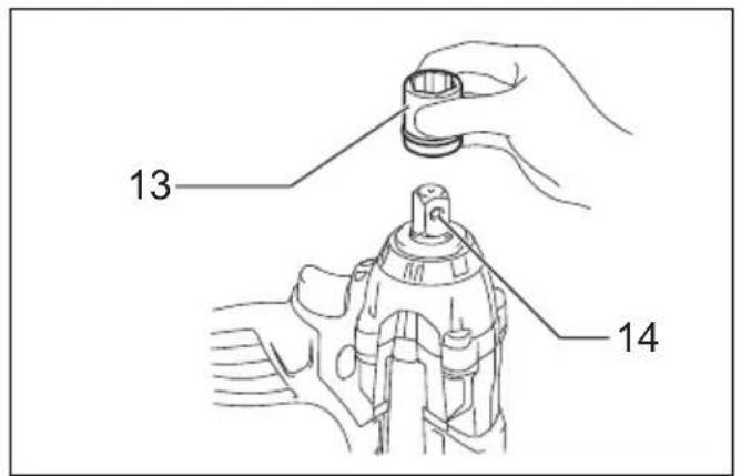
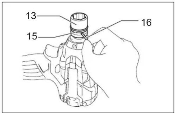
Installing or removing socket (Fig. 9 & 10)
For socket without O-ring and pin
Align the hole in the side of the socket with the detent pin on the square drive and push the socket onto the square drive until it locks into place. Tap it lightly if required.
To remove the socket, simply pull it off.
For socket with O-ring and pin
Move the O-ring out of the groove in the socket and remove the pin from the socket. Fit the socket onto the square drive so that the hole in the socket is aligned with the hole in the square drive. Insert the pin through the hole in the socket and square drive. Then return the O-ring to the original position in the socket groove to retain the pin. To remove the socket, follow the installation procedures in reverse.
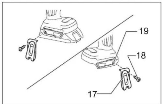
Hook (Fig. 11)
The hook is convenient for temporarily hanging the tool. This can be installed on either side of the tool.
To install the hook, insert it into a groove in the tool housing on either side and then secure it with a screw. To remove, loosen the screw and then take it out.
OPERATION

CAUTION:
- Always insert the battery cartridge all the way until it locks in place. If you can see the red part on the upper side of the button, it is not locked completely. Insert it fully until the red part cannot be seen. If not, it may accidentally fall out of the tool, causing injury to you or someone around you.
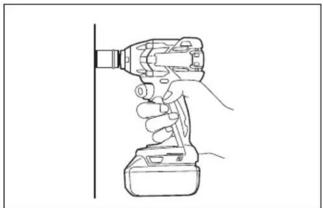
Hold the tool firmly and place the socket over the bolt or nut. Turn the tool on and fasten for the proper fastening time. (Fig. 12)
The proper fastening torque may differ depending upon the kind or size of the bolt, the material of the workpiece to be fastened, etc. The relation between fastening torque and fastening time is shown in the figures.
Model DTW280 (Fig. 13 & 14)
Model DTW281 (Fig. 15 & 16)
NOTE:
- Hold the tool pointed straight at the bolt or nut.
- Excessive fastening torque may damage the bolt/nut or socket. Before starting your job, always perform a test operation to determine the proper fastening time for your bolt or nut.
- If the tool is operated continuously until the battery cartridge has discharged, allow the tool to rest for 15 minutes before proceeding with a fresh battery cartridge.
The fastening torque is affected by a wide variety of factors including the following. After fastening, always check the torque with a torque wrench.
-
When the battery cartridge is discharged almost completely, voltage will drop and the fastening torque will be reduced.
-
Socket
-
Failure to use the correct size socket will cause a reduction in the fastening torque.
-
A worn socket (wear on the hex end or square end) will cause a reduction in the fastening torque.
-
Bolt
-
Even though the torque coefficient and the class of bolt are the same, the proper fastening torque will differ according to the diameter of bolt.
-
Even though the diameters of bolts are the same, the proper fastening torque will differ according to the torque coefficient, the class of bolt and the bolt length.
-
The use of the universal joint or the extension bar somewhat reduces the fastening force of the impact wrench. Compensate by fastening for a longer period of time.
-
The manner of holding the tool or the material of driving position to be fastened will affect the torque.
- Operating the tool at low speed will cause a reduction in the fastening torque.
MAINTENANCE

CAUTION:
- Always be sure that the tool is switched off and the battery cartridge is removed before attempting to perform inspection or maintenance.
- Never use gasoline, benzine, thinner, alcohol or the like. Discoloration, deformation or cracks may result.
To maintain product SAFETY and RELIABILITY, repairs, any other maintenance or adjustment should be performed by Makita Authorized Service Centers, always using Makita replacement parts.
OPTIONAL ACCESSORIES

CAUTION:
- These accessories or attachments are recommended for use with your Makita tool specified in this manual. The use of any other accessories or attachments might present a risk of injury to persons. Only use accessory or attachment for its stated purpose.
If you need any assistance for more details regarding these accessories, ask your local Makita Service Center.
- Sockets
- Extension bar
- Universal joint
- Bit adapter
- Makita genuine battery and charger
NOTE:
- Some items in the list may be included in the tool package as standard accessories. They may differ from country to country.
Noise
The typical A-weighted noise level determined according to EN60745:
Sound pressure level ( L_pA ): 96 dB (A)
Sound power level ( L_WA ): 107 dB (A)
Uncertainty (K): 3 dB (A)
Wear ear protection
ENG900-1
Vibration
The vibration total value (tri-axial vector sum) determined according to EN60745:
Model DTW280
Work mode: impact tightening of fasteners of the maximum capacity of the tool
Vibration emission ( a_h ): 14.0 m/s ^2
Uncertainty (K): 1.5 m/s ^4
Model DTW281
Work mode: impact tightening of fasteners of the maximum capacity of the tool
Vibration emission ( a_h ): 11.5 m/s ^2
Uncertainty (K): 1.5 m/s ^4
ENG901-1
- The declared vibration emission value has been measured in accordance with the standard test method and may be used for comparing one tool with another.
- The declared vibration emission value may also be used in a preliminary assessment of exposure.
WARNING:
- The vibration emission during actual use of the power tool can differ from the declared emission value depending on the ways in which the tool is used.
- Be sure to identify safety measures to protect the operator that are based on an estimation of exposure in the actual conditions of use (taking account of all parts of the operating cycle such as the times when the tool is switched off and when it is running idle in addition to the trigger time).
For European countries only
EC Declaration of Conformity
Makita declares that the following Machine(s):
Designation of Machine:
Cordless Impact Wrench
Model No./ Type: DTW280, DTW281
Conforms to the following European Directives:
2006/42/EC
They are manufactured in accordance with the following
Standard or standardized documents:
EN60745
The technical file in accordance with 2006/42/EC is available from:
Makita, Jan-Baptist Vinkstraat 2, 3070, Belgium
30.7.2013
Yasushi Fukaya
Director
Makita, Jan-Baptist Vinkstraat 2, 3070, Belgium
Descriptif
Vibrationsemission ( a_h ): 14,0 m/s ^2
OPTIONELE ACCESSOIRES
LET OP:
- Intended use
- General Power Tool Safety Warnings
- CORDLESS IMPACT WRENCH SAFETY WARNINGS
- SAVE THESE INSTRUCTIONS.
- IMPORTANT SAFETY INSTRUCTIONS
- FOR BATTERY CARTRIDGE
- FUNCTIONAL DESCRIPTION
- CAUTION:
- Installing or removing battery cartridge (Fig. 1)
- Battery protection system (Lithium-ion battery with star marking) (Fig. 2)
- Indicating the remaining battery capacity (Fig. 3)
- NOTE:
- Switch action (Fig. 4)
- Lighting up the front lamp (Fig. 5 & 6)
- Reversing switch action (Fig. 7)
- ASSEMBLY
- Selecting correct socket
- Installing or removing socket (Fig. 9 & 10)
- For socket without O-ring and pin
- For socket with O-ring and pin
- Hook (Fig. 11)
- OPERATION
- Model DTW280 (Fig. 13 & 14)
- Model DTW281 (Fig. 15 & 16)
- MAINTENANCE
- OPTIONAL ACCESSORIES
- Noise
- Wear ear protection
- Vibration
- Model DTW280
- Model DTW281
- WARNING:
- For European countries only
- EC Declaration of Conformity
- OPTIONELE ACCESSOIRES
- LET OP:
Brand : MAKITA
Model : DTW281RMJ
Category : Drill driver