
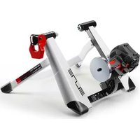
Qubo Digital Smart B+ - Home trainer Ozone - Free user manual and instructions
Find the device manual for free Qubo Digital Smart B+ Ozone in PDF.


| Product type | Smart home trainer |
| Brand | Ozone |
| Model | Qubo Digital Smart B+ |
| Dimensions (folded) | Approximately 60 x 50 x 30 cm |
| Weight | Approximately 12 kg |
| Power supply | 12V power adapter (included) |
| Maximum resistance | 2000 watts |
| Resistance type | Electromagnetic |
| Connectivity | Bluetooth, ANT+ |
| Application compatibility | Zwift, TrainerRoad, Rouvy, etc. |
| Power measurement | Built-in, accuracy +/- 2% |
| Slope simulation | Up to 15% |
| Maintenance and cleaning | Clean with a dry cloth; check bolts regularly |
| Safety | Non-slip feet; automatic shutdown in case of overheating |
| Spare parts and repairability | Available on Ozone website; repair by authorized center |
Frequently Asked Questions - Qubo Digital Smart B+ Ozone
User questions about Qubo Digital Smart B+ Ozone
0 question about this device. Answer the ones you know or ask your own.
Ask a new question about this device
Download the instructions for your Home trainer in PDF format for free! Find your manual Qubo Digital Smart B+ - Ozone and take your electronic device back in hand. On this page are published all the documents necessary for the use of your device. Qubo Digital Smart B+ by Ozone.
USER MANUAL Qubo Digital Smart B+ Ozone
natural_image
Exterior view of a modern white and black bicycle brake lever with attached bracket (no text or symbols visible)QUBO
ISTRUZIONI PER L'USO DEL TELAIO
FRAME ASSEMBLY INSTRUCTIONS
INTRODUZIONE
natural_image
Technical line drawing of a mechanical bracket component (no text or symbols)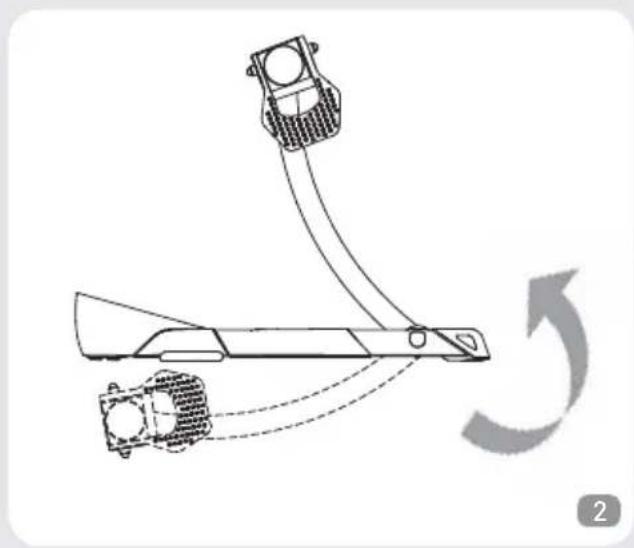
natural_image
Diagram of a mechanical device with curved and dashed motion arrows indicating rotation (no text or symbols)natural_image
Technical line drawing of a mechanical assembly with no visible text or symbols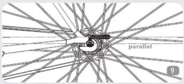
natural_image
Technical diagram of a mechanical assembly with angular dimension标注 (55°), no readable text or symbols present.
natural_image
Technical line drawing of a mechanical assembly with angular dimension标注 (65°), no readable text or symbols present.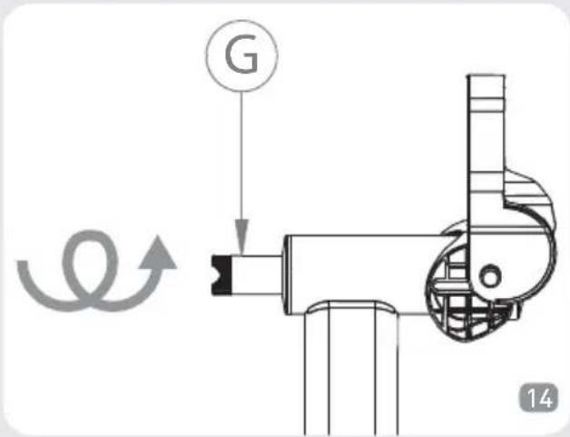
natural_image
Technical line drawing of a mechanical assembly or assembly (no text or symbols visible)
natural_image
Technical line drawing of a mechanical component with no visible text or symbols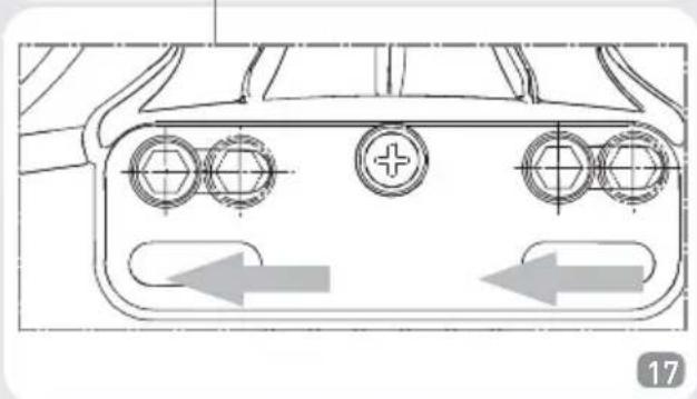
natural_image
Technical line drawing of a connector with three circular ports and directional arrows indicating movement (no text or symbols)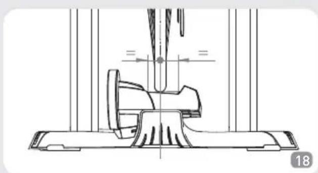
natural_image
Technical line drawing of a mechanical assembly with no visible text or symbolsnatural_image
Line drawing of a bicycle with wheels and a side-mounted wheel, showing no text or symbolsnatural_image
Mechanical assembly diagram showing a rotating bicycle wheel with a force F applied, no text or symbols presentnatural_image
Illustration of a person using a device to lift a vehicle, with an arrow indicating motion (no text or symbols)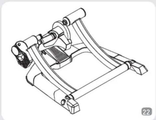
natural_image
Technical line drawing of a mechanical device with curved components and mounting brackets (no text or symbols)natural_image
Diagram of a robotic arm with motion arrows indicating rotation (no text or symbols)
natural_image
Technical line drawing of a mechanical bracket component (no text or symbols)
ATTENZIONI
Thank you for choosing the Qubo

INTRODUCTION
Check the presence of all the following components:
N°1 Qubo frame (Ref. A)
N°1 Unit (Ref. B)
N°1 Quick release (Ref. C)
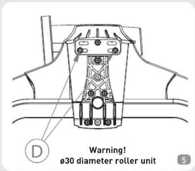
N°2 M6 Unit screws (D)
N°10 Levelling (equalizing) feet (E)

ATTENTION

Resistance unit depicted here may vary from production models
UNIT ASSEMBLY
- Unfold the frame (A) from its packaged position (Fig. 1) and place it on a flat surface (Fig. 2)

natural_image
Technical line drawing of a mechanical bracket component (no text or symbols)
natural_image
Diagram of a mechanical device with two components and curved arrows indicating motion (no text or symbols)- There are 2 pairs of holes on its base to be used with different roller diameter options:
1) Use the front pair of holes for a 30mm diameter roller unit (Fig. 3);
2) Use the rear pair of holes for a 45mm diameter roller unit (Fig. 4);


- Tighten the M6 screws (D) (Fig. 5 and Fig. 6) completely, utilizing the correct holes for the different roller diameter options.

FITTING THE BICYCLE
- Make sure the quick release of the bicycle rear wheel is properly fixed.
- Turn the lever (F) to the "open" position (Fig. 7).

- Put the bicycle in position, inserting the left end of the rear quick release in the left bushing (Fig. 8). For safer clamping of the bicycle on the stand, make sure the lever of the quick release is horizontal (Fig. 9).

natural_image
Technical line drawing of a mechanical assembly with no visible text or symbols
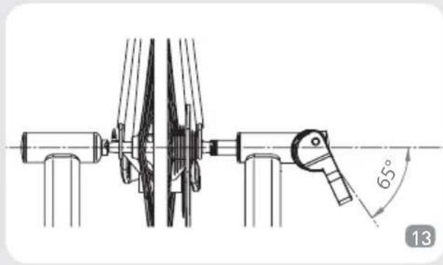
- Close the lever (F), making sure it starts pressing the quick release inside the predefined work area; between 55^ and 65^ (Fig. 10).

- If the lever (F) starts pressing the quick release in the advanced work position (Fig. 11), screw the left bushing pin (g) (Fig. 12) so that the lever (F) starts working inside the predefined work area (between 55^ and 65^ ) (Fig. 10).

natural_image
Technical diagram of a mechanical assembly with angular dimension标注 (55°), no readable text or symbols present.
- If the lever (F) starts pressing the quick release in the delayed work position (Fig. 13), unscrew the left bushing pin (G) (Fig. 14) so that the lever starts working inside the predefined work area (between 55^ and 65^ ). (Fig. 10).
natural_image
Technical line drawing of a mechanical assembly with angular dimension标注 (65°), no readable text or symbols present.
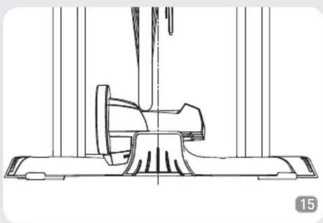
- If the bicycle wheel sets up too far from the centre of the roller (Fig. 15), loosen the resistance unit (B) attachment bolts (D), slide the resistance
unit left or right as necessary, and re-tighten the bolts (Fig.16, Fig.17 and Fig.18).
natural_image
Technical line drawing of a mechanical assembly or assembly (no text or symbols visible)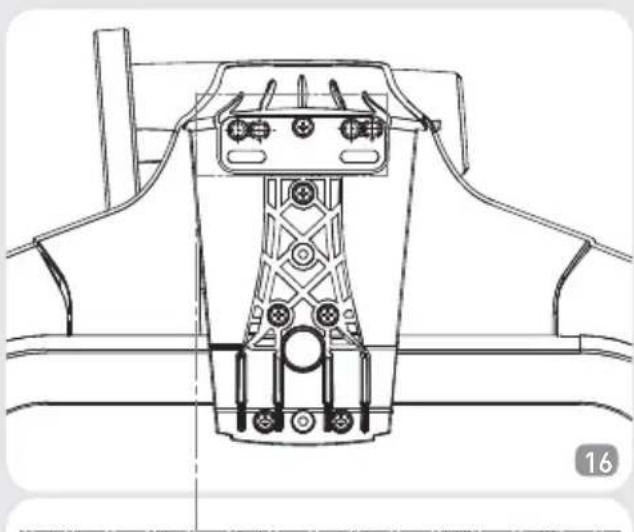
natural_image
Technical line drawing of a mechanical component with no visible text or symbols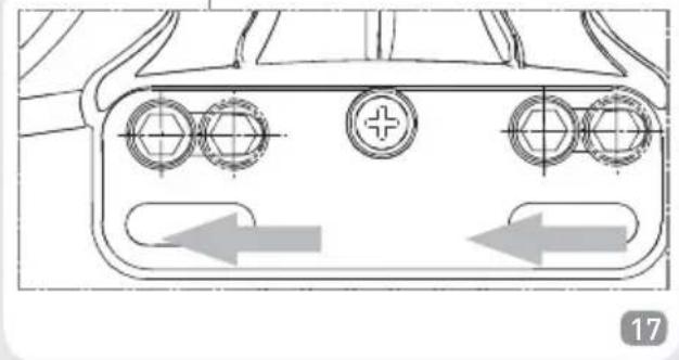
natural_image
Technical diagram of a device rear panel with three circular components and directional arrows indicating movement (no text or symbols)
natural_image
Technical line drawing of a mechanical assembly with no visible text or symbols- Push the bicycle towards the resistance unit until the rear wheel touches the roller (Fig. 19).

natural_image
Line drawing of a bicycle with wheels and a handle, showing a left-side motion arrow (no text or symbols)- Verify the stability of the bike by pushing and pulling the horizontal tube of the frame and the saddle. Should the bike still not appear stable, make sure its quick release and lever are correctly positioned, that the lever (F) is in a "closed" position and the adjusting of the clamping system has been carried out correctly.
BIKE REMOVAL
- Hold the bicycle with one hand and with the other open the lever (F), turning it to the "open" position (Fig. 20). Remove the bicycle.

natural_image
Mechanical assembly diagram showing a rotating wheel with a force F applied, no text or symbols present- For carrying, or storage, it is advisable to close the stand. (Fig.21 e Fig.22).

natural_image
Illustration of a person using a device to lift a vehicle, with no visible text or symbols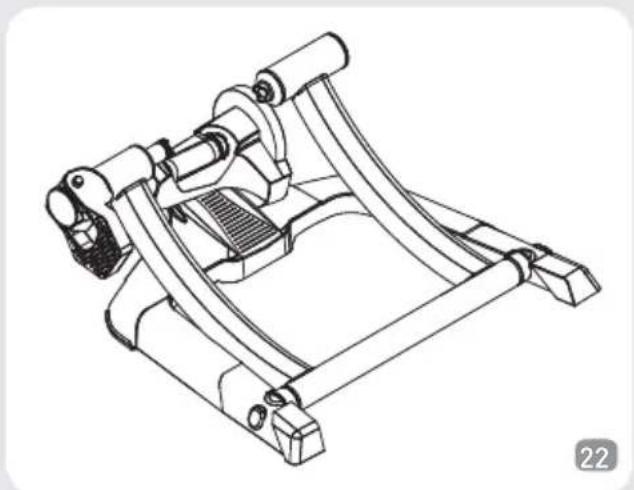
natural_image
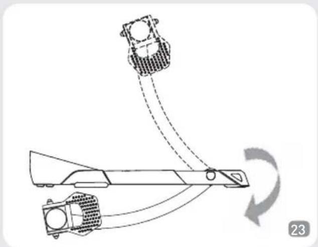
Technical line drawing of a mechanical device with curved brackets and mounting feet (no text or symbols)- In order to further reduce the storage footprint remove the unit (B) from the frame (A) and place it back in its original packaging and fold the frame as indicated in Fig. 23 and Fig. 24.
natural_image
Diagram of a robotic arm with motion arrows indicating rotation (no text or symbols)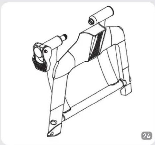
natural_image
Technical line drawing of a mechanical bracket component (no text or symbols)LEVELLING FEET ASSEMBLY
- The Cube frame (A) comes equipped with levelling feet (E) to compensate for uneven surfaces that do not allow the four feet to make complete contact, and to allow the bike to be perfectly vertical (Fig. 25).

- The levelling feet (E) can be mounted under the front feet (Fig. 26 and Fig. 27).


- The levelling feet (E) can be mounted under the rear feet (Fig. 28 and Fig. 29).


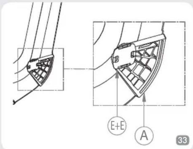
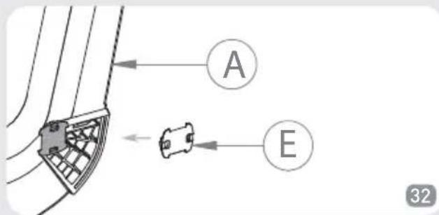
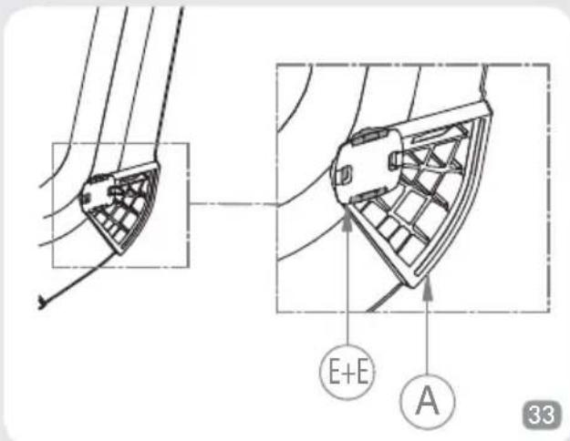
- If a single levelling foot (E) isn't sufficient, it is possible to add additional feet to those already mounted. (Fig. 30, Fig. 31, Fig. 32 and Fig. 33).
Warning: the direction of the foot (E) is turned 90° in relation to the first one positioned.



ATTENTION
- Keep people, children and animals away from the roller during use, since the moving and rotating parts of the roller and the bicycle can cause damage in case of contact.
- Before starting training, position the trainer in a dry place, away from potentially hazardous objects (furniture, tables, chairs, etc.) in order to avoid any risk of inadvertent or accidental contact with them.
- The stand is designed for use by just one cyclist.
- Check the safety and stability of the bicycle before every training session.
- If the quick release is not compatible with the bushings of the stand, replace it with the one supplied (C).
- There are no individually usable components on the inside.
- Since the feet are made from soft non-slip material, during use they may leave rubber marks on the floor.
ADVICE ON USE
- For less tyre wear and better grip on the roller, it is advisable to use tyres of 23 mm width.
- Recommended rear wheel pressure: 7 -8 atmospheres for racing tyres; 3.5 - 4 atmospheres for MTB tyres. For particular cases, comply with the pressure recommended by the tyre manufacturer.
- For quieter use, better grip of the tyre on the roller and reduced vibration, use slick tyres (also for Mountain bikes).
- Before use, clean the tyre with alcohol or water.
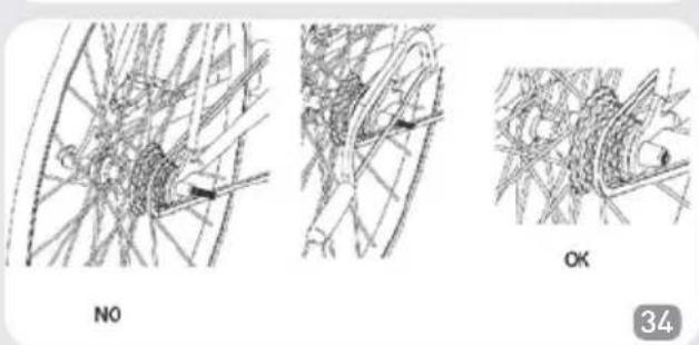
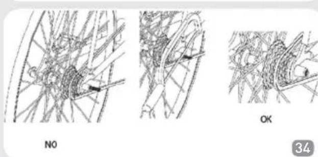
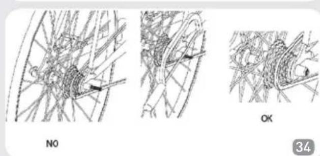
- If the pin of the quick release supplied protrudes more than 3 mm from the fixing nut, cut off the protruding part (Fig. 34).
EINLEITUNG
natural_image
Technical line drawing of a mechanical bracket component (no text or symbols)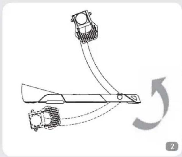
natural_image
Diagram of a mechanical device with curved arrows indicating motion or rotation, no text or symbols presentnatural_image
Technical line drawing of a mechanical assembly with no visible text or symbols
natural_image
Technical line drawing of a mechanical assembly with angular dimension标注 (55°), no readable text or symbols present.
natural_image
Technical line drawing of a mechanical assembly with angular dimension标注 (65°), no readable text or symbols present.
natural_image
Technical line drawing of a mechanical assembly or tool component (no text or symbols visible)
natural_image
Technical line drawing of a mechanical component with no visible text or symbols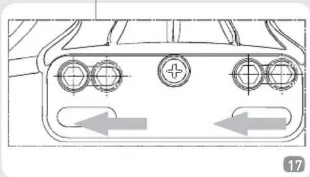
natural_image
Technical line drawing of a mechanical component with circular features and directional arrows (no text or symbols)
natural_image
Technical line drawing of a mechanical assembly with no visible text or symbolsnatural_image
Line drawing of a bicycle with wheels and a side-mounted wheel, showing no text or symbolsnatural_image
Mechanical assembly diagram showing a rotating wheel with a force F applied, no text or symbols presentnatural_image
Illustration of a person using a device to lift a vehicle, with an arrow indicating motion (no text or symbols)
natural_image
Technical line drawing of a mechanical device with curved components and mounting brackets (no text or symbols)natural_image
Diagram of a mechanical device with two components and a curved arrow indicating rotation (no text or symbols)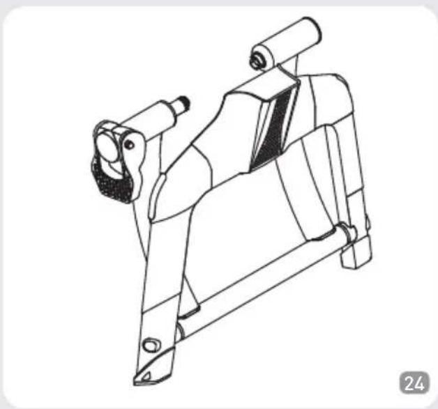
natural_image
Technical line drawing of a mechanical bracket component (no text or symbols)MONTAGE DER AUSNIVELLIERENDEN STÜTZFÜSSE
INTRODUCTION
natural_image
Technical line drawing of a mechanical bracket component (no text or symbols)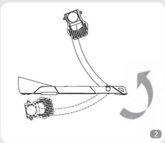
natural_image
Diagram of a mechanical device with two components and curved motion arrows indicating rotation (no text or symbols)natural_image
Technical line drawing of a mechanical assembly with no visible text or symbols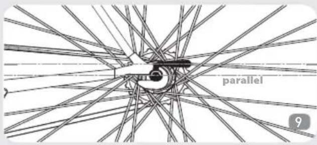
natural_image
Technical diagram of a mechanical assembly with angular dimension标注 (55°), no readable text or symbols present.
natural_image
Technical line drawing of a mechanical assembly with angular dimension标注 (65°), no readable text or symbols present.
natural_image
Technical line drawing of a mechanical assembly or tool component (no text or symbols visible)
natural_image
Technical line drawing of a mechanical component with no visible text or symbols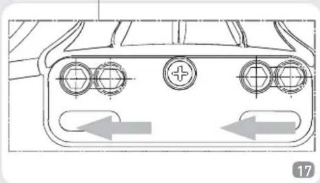
natural_image
Technical line drawing of a connector with three circular ports and directional arrows indicating movement (no text or symbols)
natural_image
Technical line drawing of a mechanical assembly with no visible text or symbolsnatural_image
Line drawing of a bicycle with wheels and a handle, showing front wheel and side seat (no text or symbols)ENLÈVEMENT DE LA BICYCLETTE
natural_image
Mechanical assembly diagram showing a rotating wheel with a force F applied, no text or symbols presentnatural_image
Illustration of a person using a device to lift a vehicle, with an arrow indicating motion (no text or symbols)
natural_image
Technical line drawing of a mechanical device with curved components and mounting brackets (no text or symbols)natural_image
Diagram of a mechanical device with two components and a curved arrow indicating rotation (no text or symbols)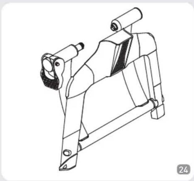
natural_image
Technical line drawing of a mechanical bracket component (no text or symbols)ASSEMBLAGE DES PIEDS DE NIVELAGE

ATTENTION
INTRODUCCIÓN
N°1 Bastidor Qubo (Ref. A)
N°1 Unità (Ref. B)
N°1 Sgancio Rapido (Ref. C)
natural_image
Technical line drawing of a mechanical bracket component (no text or symbols)
natural_image
Diagram of a mechanical device with curved and dashed motion arrows indicating rotation (no text or symbols)natural_image
Technical line drawing of a mechanical assembly with no visible text or symbols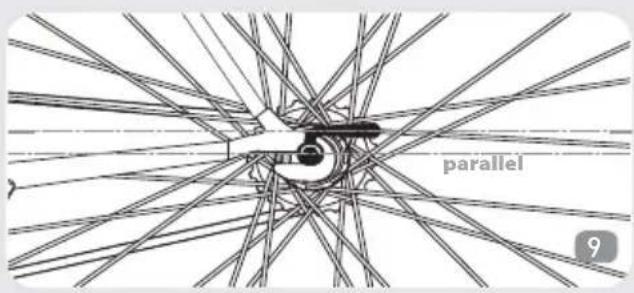
natural_image
Technical line drawing of a mechanical assembly with angular dimension标注 (55°), no readable text or symbols present.
natural_image
Technical line drawing of a mechanical assembly with angular dimension标注 (65°), no readable text or symbols present.
natural_image
Technical line drawing of a mechanical assembly or tool component (no text or symbols visible)
natural_image
Technical line drawing of a mechanical component with no visible text or symbols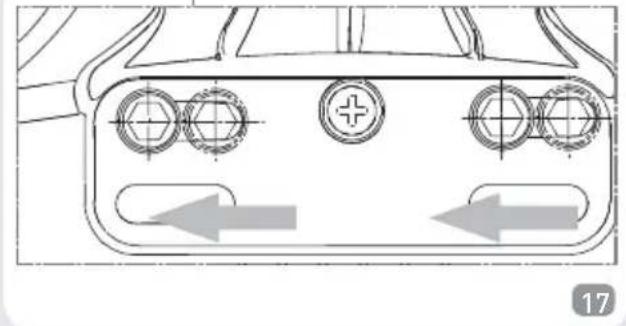
natural_image
Technical line drawing of a connector with three circular ports and directional arrows indicating movement (no text or symbols)
natural_image
Technical line drawing of a mechanical assembly with no visible text or symbolsnatural_image
Line drawing of a bicycle with wheels and a side-mounted wheel, showing a change in the front wheel (no text or symbols)CÓMO SACAR LA BICICLETA
natural_image
Mechanical assembly diagram showing a rotating arm and wheel assembly (no text or symbols)natural_image
Illustration of a person using a device to lift a vehicle, with an arrow indicating motion (no text or symbols)
natural_image
Technical line drawing of a mechanical device with curved brackets and mounting feet (no text or symbols)natural_image
Diagram of a mechanical device with two components and a curved arrow indicating rotation (no text or symbols)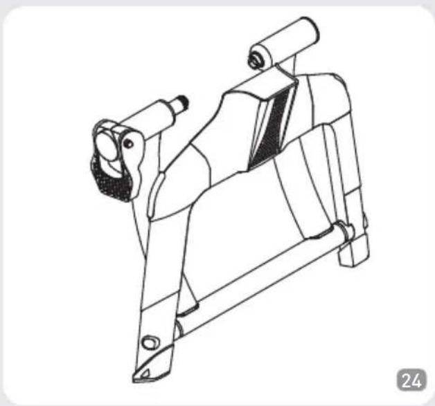
natural_image
Technical line drawing of a mechanical bracket component (no text or symbols)MONTAJE PIES DE NIVELADO
natural_image
Three technical diagrams showing wire mesh structures with arrows indicating features, labeled NO and OK (no text or symbols beyond labels)ATENCIÓN
INLEIDING
N°1 Qubo frame (Ref. A)
natural_image
Technical line drawing of a mechanical bracket component (no text or symbols)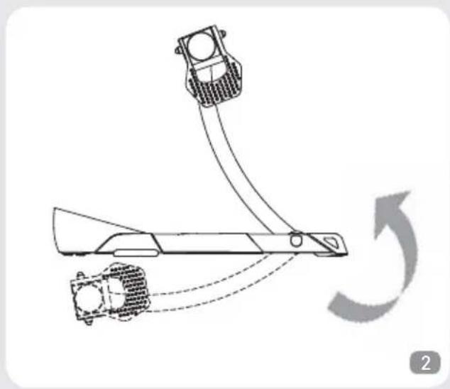
natural_image
Diagram of a mechanical device with curved arrows indicating motion or rotation, no text or symbols presentnatural_image
Technical line drawing of a mechanical assembly with no visible text or symbols
natural_image
Technical diagram of a mechanical assembly with angular dimension标注 (55°), no readable text or symbols present.
natural_image
Technical line drawing of a mechanical assembly with angular dimension标注 (65°), no readable text or symbols present.
natural_image
Technical line drawing of a mechanical assembly or tool component (no text or symbols visible)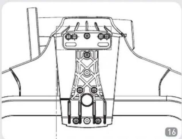
natural_image
Technical line drawing of a mechanical component with no visible text or symbols
natural_image
Technical line drawing of a mechanical component with three circular ports and directional arrows indicating movement (no text or symbols)
natural_image
Technical line drawing of a mechanical assembly with no visible text or symbolsnatural_image
Line drawing of a bicycle with wheels and a curved handle, showing front wheel and side seat (no text or symbols)natural_image
Mechanical assembly diagram showing a rotating wheel with a force F applied, no text or symbols presentnatural_image
Illustration of a person using a device to lift a vehicle, with an arrow indicating motion (no text or symbols present)
natural_image
Technical line drawing of a mechanical device with curved brackets and mounting feet (no text or symbols)natural_image
Diagram of a mechanical device with rotating components and curved motion lines (no text or symbols)
natural_image
Technical line drawing of a mechanical bracket component (no text or symbols)MONTAGE VAN DE STELPOTEN


OPGELET


- QUBO
- INTRODUZIONE
- ATTENZIONI
- Thank you for choosing the Qubo
- INTRODUCTION
- ATTENTION
- UNIT ASSEMBLY
- FITTING THE BICYCLE
- BIKE REMOVAL
- LEVELLING FEET ASSEMBLY
- ADVICE ON USE
- EINLEITUNG
- MONTAGE DER AUSNIVELLIERENDEN STÜTZFÜSSE
- ENLÈVEMENT DE LA BICYCLETTE
- INTRODUCCIÓN
- CÓMO SACAR LA BICICLETA
- MONTAJE PIES DE NIVELADO
- ATENCIÓN
- INLEIDING
- MONTAGE VAN DE STELPOTEN
- OPGELET
Brand : Ozone
Model : Qubo Digital Smart B+
Category : Home trainer