
CG 14DSDL - Brush cutter HiKOKI - Free user manual and instructions
Find the device manual for free CG 14DSDL HiKOKI in PDF.


| Product Type | Cordless Brush Cutter (Grass Trimmer) |
| Model | CG 14DSDL |
| Pole Type | Straight type |
| Cutting Diameter | 310 mm |
| No-Load Speed | 5000 min⁻¹ |
| Rotation Direction | Counterclockwise as seen from above |
| Battery Voltage / Capacity | 14.4 V (Li-ion 3.0 Ah, 8 cells) |
| Battery Model | BSL1430 |
| Charger Model | UC18YGSL |
| Operating Time per Charge | 17–18 minutes (full speed, 310 mm head) |
| Weight (with battery, head, cover) | 4.1 kg |
| Cutting Line | Nylon line, diameter 1.4 mm, length 6 m |
| Line Feed Mechanism | Semi-automatic (tap head on ground) |
| Safety Features | Auto power-off after 1 min inactivity, overload protection, overheat protection, lock lever |
| Power Indicators | Power lamp (red when ON, blinking for protection active), remaining battery indicator |
| Handle Type | Loop handle with adjustable fixture |
| Included Accessories | Nylon head, cover, hex bar wrench (4 mm), 17×19 combi box wrench, protective glasses, battery (BSL1430), charger (UC18YGSL) |
| Maintenance Requirements | Check carbon brushes (replace when worn to limit), clean exterior with soft cloth, inspect nylon head regularly |
| Repair / Service | Only by HiKOKI Authorized Service Center using genuine parts |
| Sound Power Level (Guaranteed) | 88 dB(A) |
| Vibration Emission Value | 1.8 m/s² (triax vector sum) |
Frequently Asked Questions - CG 14DSDL HiKOKI
User questions about CG 14DSDL HiKOKI
0 question about this device. Answer the ones you know or ask your own.
Ask a new question about this device
Download the instructions for your Brush cutter in PDF format for free! Find your manual CG 14DSDL - HiKOKI and take your electronic device back in hand. On this page are published all the documents necessary for the use of your device. CG 14DSDL by HiKOKI.
USER MANUAL CG 14DSDL HiKOKI
natural_image
Technical line drawing of a mechanical device labeled CG18DSDL, showing a lever and wheel assembly (no text or symbols on the diagram itself)natural_image
Technical line drawing of a mechanical component with dimension label (39) and no readable text or symbols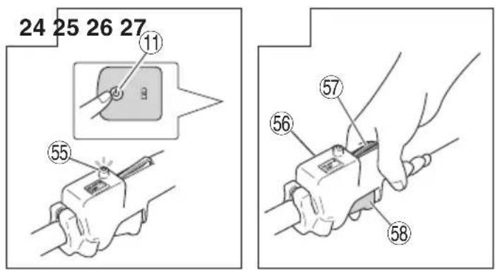
natural_image
Pure mechanical diagram showing a circular component with a triangular head and two hanging weights, no text or symbols present.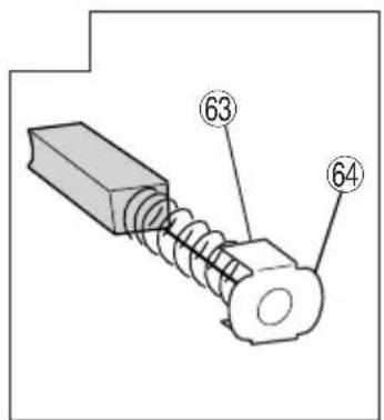
| Svenska Dansk | Norsk Suomi English | ||||
| 1 | Uppladdningsbart batteri | Genopladeligt batteri | Oppladbart batteri Lad | attava paristo | Rechargeable battery |
| 2 | Lås Smæklås Sperre | hake Salpa Latch | |||
| 3 | Batterilock Batteridæksel Batteri deksel Akunkansi Battery cover | ||||
| 4 | Poler | Terminaler | Tilkoblingspunkter | Navat | Terminals |
| 5 | Ventilationshål | Ventilationsåbninger | Ventilasjons hull | Tuuletusaukot | Ventilation holes |
| 6 | Tryck | Tryk | Trykk | Paina | Push |
| 7 | Tryck inåt | Læg i | Setti | Paina sisää | Insert |
| 8 | Dra ut | Træk ud | Dra ut | Vedä | Pull out |
| 9 | Signallampa | Kontrollampe | Pilot-lys | Markkivalo | Pilot lamp |
| 10 | Efter isättning | Efter isætning | Etter innsetting | Asennuksen jälkeen | After insert |
| 11 | Strömknapp | Tænd/Sluk knap | Strømknapp | Virtapainike | Power button |
| 12 | Indikeringslampa för kvarvarande batteri | Indikatorlampe for resterende batteri | Indikatorlampe for gjenværende batterinivå | Jäljellä olevan latauksen merkkivalo | Remaining battery indicator lamp |
| 13 | Huvudrör | Hovedrør | Hovedrør | Pääputki | Main pipe |
| 14 | Kåpsida | Husside | Hus-siden | Kotelopuoli | Housing side |
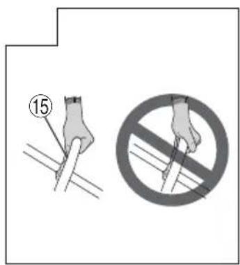
| 15 | Remhandtag | Loophåndtag | løkkehåndtak | Silmukkakahva | Loop handle |
| 16 | Handtagsfäste | Håndtag | Håndtakfeste | Kahvan kiinnike | Handle fixture |
| 17 | M6×43-bultar | M6×43-bolte | M6×43 bolter | M6×43-pultit | M6×43 bolts |
| 18 | M6-muttrar | M6-møtrikker | M6 mutter | M6-mutterit | M6 nuts |
| 19 | Kåpa Dæksel | Deksel Kansi | Cover | ||
| 20 | Kniv | Kniv | Kniv | Veitsi | Knife |
| 21 | D5 gångskärande skruv | D5-skrue | D5 selvgjengede skrue | D5-kierreruuvi | D5 tapping screw |
| 22 | Kåpans fäste | Dækselbeslag | Dekkeklamme | Kannensalpa | Cover bracket |
| 23 | M6×25 sexkantbultar till fästet | M6×25-unbrakobolte | M6×25 hex. knapphylse bolter | M6×25-kuusiokolonappipultit | M6×25 hex. socket button bolts |
| 24 | Kåpans hållare | Dækselholder | Overtreksholder | Kannenpidin | Cover holder |
| 25 | Flänsenhet | Flangesamling | Flenseenhet | Laippa-asennus | Flange ass'y |
| 26 | Vinge Vinge | Vinge Siipi | Wing | ||
| 27 | Motorhölje Motorkasse | Motorhus Moottorinkotelo | Motor case | ||
| 28 | Sexkantsnyckel 4mm | 4mm Unbrakonøgle | Sekskantnøkkel 4 mm | Kuusiokoloavain 4 mm | Hex. bar wrench 4mm |
| 29 | Gångat fäste på motorkåpa | Bolt med gevind på motorhuset | Gjenget strammer for motorhuset | Moottorikotelon kierteinen kiinnike | Threaded fastener of the motor case |
| 30 | Hål | Hul | Hull | Reikä | Hole |
| 31 | Nylonhuvud | Nylonhoved | Nylonhode | Nailonpää | Nylon head |
| 32 | Skruv (vänstergångad) | Skrue (venstre rotation) | Skrue (venstrerotasjon) | Ruuvi (kierto vastapäivään) | Screw (left rotation) |
| 33 | Nylonlina | Nylonsnor | Nylontråd | Nylonlanka | Nylon line |
| 34 | Slå | Bank | Tappe | Kopauta | Tap |
| 35 | Knapp | Knap Knapp | Painike | Button | |
| 36 | Tryck/släpp | Tap/frigivelse | Tapp/utlöser | Napauta/vapauta | Tap/release |
| 37 | Markering avnötningsgräns (2 markeringar) | Slidegrænsemærke (2 mærker) | Slitegrensemerke (2 merker) | Kulutusrajan merkki (2 merkkiä) | Wear limit mark (2 marks) |
| 38 | Förlängning i 30 mm intervaller | Udvides i 30mm intervaller | Utvidelser i trinn på 30 mm | Pitenee 30 mm:n lisäyksin | Extends in 30 mm increments |
| 39 | Ungefärlig längd 90 - 110 mm | Ca. længde 90 - 110mm | Passende lengde 90 - 110 mm | Oikea pituus 90 - 110 mm | Appropriate length 90 - 110 m |
| 40 | Kåpa Dæksel | Deksel Kansi | Cover | ||
| 41 | Fodral Hus Hus Kotelp | Case | |||
| 42 | Krok Krog Krok Koukku Hook | ||||
| 43 | Tryckfl ikar (2 platser) | Tryktapper(2 områder) | Trykkfl iker(2 områder) | Painokorvakkeet(2 aluetta) | Press tabs (2 areas) |
| 44 | Rulle Hjul Spole Kela | Reel | |||
| 45 | Skåra Rille Spor Ura | Groove | |||
| 46 | Rullhål | Hul i hjul | Hull i spole | Kelan reikä | Hole of reel |
| 47 | Riktning att Lindanylonlina | Drejeretning tilnylonsnor | Retning å spolenylontråd | Nailonlangankelaussuunta | Direction to windnylon cord |
| 48 | Fäst i stoppet | Fastgør på proppen | Sikre i stopperen | Kiinnipysäytyslaitteessa | Secure in the stopper |
| 49 | Stopp | Proppe | Stopper | Pysäytyslaite | Stopper |
| 50 | Linstyrhål | Snørehul guide | Trådførerøye | Reikälanganohjain | Eyelet line guide |
| 51 | Medan vindan hålls | Mens du holder hjulet | Mens spolen holdes | Kelaa pidettäessä | While holding thereel |
| 52 | Träd linan igenomlinstyrhålet | Put snøren gennemsnørehullet | Træ tråden gjennomtrådførerøyet | Pujota lankareikälanganohjaimenläpi | String the linethrough the eyeletline guide |
| 53 | Låshål för kåpa(2 hål) | Låsning af huller pådækslet (2 huller) | Dekselets låsehull(2 hull) | Kannen lukitusreiät(2 holes) | Locking holes ofcover (2 holes) |
| 54 | Flikar på kåpa(2 fl ikar) | Tapper på dæksel(2 tapper) | Fliker på huset(2 fl iker) | Kotelon korvakkeet(2 korvaketta) | Tabs of case (2 tabs) |
| 55 | Strömindikator | Tændt-lampe | Strømlys | Virtalamppu | Power lamp |
| 56 | Handtag | Håndtag | Håndtak | Kahva | Handle |
| 57 | Låsspak | Låsearm | Låsespake | Lukitusvipu | Lock lever |
| 58 | Spak Arm | Spake Vipu Lever | |||
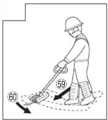
| 59 | Framåt | Fremad | Fremover | Eteenpäin | Forward |
| 60 | Vänstra sidan | Venstre side | Venstre side | Vasen sivu | Left side |
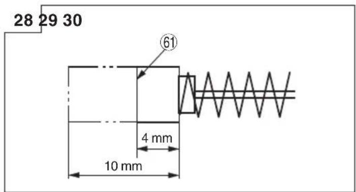
| 61 | Avnötningsgräns | Slidgrænse | Slitasjegrense | Kulutusraja | Wear limit |
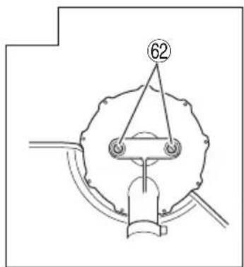
| 62 | Borstskruv | Børstedæksel | Børstehode | Harjansuojus | Brush cap |
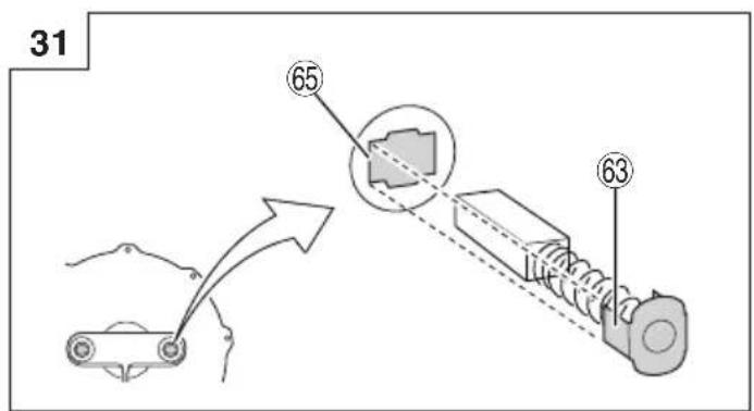
| 63 | Nagel på kolborste | Kulbørstes som | Stift på kullbørste | Hiiliharjan kynsi | Nail of carbon brush |
| 64 | Utbuktning påkolborste | Fremspring påkulbørste | Utstikkende del påkullbørsten | Hiiliharjan ulkonema | Protrusion of carbonbrush |
| 65 | Kontaktdel förborströrSymboler⚠ WARNINGNedan visas de symboler som används för maskinen. Se till att du förstår vad de betyder innan verktyget används. | Kontaktdel påbørsterørSymboler⚠ ADVARSELDet følgende viser symboler, som anvendes for maskinen.Vær sikker på, at du forstår deres betydning, inden du begynder at bruge maskinen. | Kontaktdel avbørsterørSymboler⚠ ADVARSELFølgende symboler brukes for maskinen.Sørg for å forstå betydningen av disse symbolene før maskinen tas i bruk. | HarjaputkenkosketusalueSymbolit⚠ VAROITUSSeuraavassa on näytetty koneessa käytetyt symbolit.Varmista, että ymmärrät niiden merkityksen ennen kuin aloitat koneen käytön. | Contact portion ofbrush tubeSymbols⚠ WARNINGThe following show symbols used for the machine. Be sure that you understand their meaning before use. |
 | Läs alla säkerhetsvarningar och alla instruktioner.Underlåtenhet att följa varningarna och instruktionerna nedan kan resultera i elstötar, brand och/eller allvarliga skador. | Læs alle sikkerhedsadvarsler og instruktioner.Det kan medføre elektrisk stød, brand og/eller alvorlig personskade, hvis alle advarslerne og instruktionerne nedenfor ikke overholdes. | Les alle advarsler og sikkerhetsinstruksjoner.Hvis du ikke følger alle advarsler og instruksjoner kan bruk av utstyret resultere i elektrisk støt, brann og/eller alvorlig personskade. | Lue kaikki turvallisuutta koskevat varoitukset ja kaikki ohjeet.Jos varoituksia ja ohjeita ei noudateta, on olemassa sähköiskun, tulipalon ja/tai vakavan henkilövahingon vaara. | Read all safety warnings and all instructions.Failure to follow the warnings and instructions may result in electric shock, fi re and/or serious injury. |
 | Ha alltid ögonskydd. | Brug altid beskyttelsesbriller. | Ha alltid på deg vernebriller. | Käytä aina suojalaseja. | Always wear eye protection. |
 | Bär alltid hörselskydd. | Brug altid høreværn. | Bruk hørselsvern. | Käytä aina kuulosuojaimia | Always wear hearing protection. |
 | Utsätt inte för fukt. | Må ikke udsættes for fugt. | Må ikke utsettes for fuktighet. | Älä altista kostudelle. | Do not expose to moisture. |
  | Håll åskådare på avständ. | Hold tilskuere på afstand. | Hold tilskuere unna. | Pidä sivustakatsojat poissa. | Keep bystanders away. |
 | Ta ut batteriet före justering eller rengöring och om redskapet lämnas utan tillsyn under en tid. | Tag batteriet ud inden justering eller rengöring, og inden du forlader maskinen selv for korte tidsrum. | Fjern batteri før justering eller rensing og før maskinen forlates uten tilsyn for uansett periode. | Poista akku ennen säätöä tai puhdistamista tai ennen koneen jättämistä ilman valvontaa lyhyeksikin ajaksi. | Remove battery before adjusting or cleaning and before leaving the machine unattended for any period. |
 | Gäller endast EU-länderElektriska verktyg får inte kastas i hushållssoporna!Enligt direktivet 2002/96/EG som avser äldre elektrisk och elektronisk utrustning och dess tillämpning enligt nationell lagstiftning ska uttänta elektriska verktyg sorteras separat och lämnas till miljövänlig återvinning. | Kun for EU-lande Elværktøj må ikke bortskaff es som almindeligt aff ald!I henhold til det europæiske direktiv 2002/96/EF om bortskaff else af elektriske og elektroniske produkter og gældende national lovgivning skal brugt elværktøj indsamles separat og bortskaff es på en måde, der skåner miljøet mest muligt. | Kun for EU-land Kast aldri elektroverktøy i husholdningsavfallet!I henhold til EU-direktiv 2002/96/EF om kasserte elektriske og elektroniske produkter og direktivets iverksetting i nasjonal rett, må elektroverktøy som ikke lenger skal brukes, samles separat og returneres til et miljøvennlig gjenvinningsanlegg. | Koskee vain EU-maita Alä hävitä sähkötyökalua tavallisen kotitalousjätteen mukana!Vanhoja sähkö- ja elektronikkalaitteita koskevan EU-direktiivin 2002/96/ETY ja sen maakohtaisten sovellusten mukaisesti käytetyt sähkötyökalut on toimitettava ongelmajätteen keråyspisteeseen ja ohjattava ympåristöystävälliseen kierrätykseen. | Only for EU countries Do not dispose of electric tools together with household waste material!In observance of European Directive 2002/96/EC on waste electrical and electronic equipment and its implementation in accordance with national law, electric tools that have reached the end of their life must be collected separately and returned to an environmentally compatible recycling facility. |
ALLMÄNNA SÄKERHETSVARNINGAR FÖR ELEKTRISKA VERKTYG
WARNING
BEHOLD FOR FREMTIDIG REFERANSE
Sikker bruksmåte
- Trening
VEDLIKEHOLD OG INSPEKSJON
FORSIKTIG
Read all safety warnings and all instructions.
Failure to follow the warnings and instructions may result in electric shock, fire and/or serious injury.
Save all warnings and instructions for future reference.
The term “power tool” in the warnings refers to your mains-operated (corded) power tool or battery-operated (cordless) power tool.
1) Work area safety
a) Keep work area clean and well lit.
Cluttered or dark areas invite accidents.
b) Do not operate power tools in explosive atmospheres, such as in the presence of fl ammable liquids, gases or dust.
Power tools create sparks which may ignite the dust or fumes.
c) Keep children and bystanders away while operating a power tool.
Distractions can cause you to lose control.
2) Electrical safety
a) Power tool plugs must match the outlet.
Never modify the plug in any way.
Do not use any adapter plugs with earthed (grounded) power tools.
Unmodifi ed plugs and matching outlets will reduce risk of electric shock.
b) Avoid body contact with earthed or grounded surfaces, such as pipes, radiators, ranges and refrigerators.
There is an increased risk of electric shock if your body is earthed or grounded.
c) Do not expose power tools to rain or wet conditions.
Water entering a power tool will increase the risk of electric shock.
d) Do not abuse the cord. Never use the cord for carrying, pulling or unplugging the power tool.
Keep cord away from heat, oil, sharp edges or moving parts.
Damaged or entangled cords increase the risk of electric shock.
e) When operating a power tool outdoors, use an extension cord suitable for outdoor use.
Use of a cord suitable for outdoor use reduces the risk of electric shock.
f) If operating a power tool in a damp location is unavoidable, use a residual current device (RCD) protected supply.
Use of an RCD reduces the risk of electric shock.
3) Personal safety
a) Stay alert, watch what you are doing and use common sense when operating a power tool. Do not use a power tool while you are tired or under the influence of drugs, alcohol or medication.
A moment of inattention while operating power tools may result in serious personal injury.
b) Use personal protective equipment. Always wear eye protection.
Protective equipment such as dust mask, non-skid safety shoes, hard hat, or hearing protection used for appropriate conditions will reduce personal injuries.
c) Prevent unintentional starting. Ensure the switch is in the off position before connecting to power source and/or battery pack, picking up or carrying the tool.
Carrying power tools with your finger on the switch or energising power tools that have the switch on invites accidents.
d) Remove any adjusting key or wrench before turning the power tool on.
A wrench or a key left attached to a rotating part of the power tool may result in personal injury.
e) Do not overreach. Keep proper footing and balance at all times.
This enables better control of the power tool in unexpected situations.
f) Dress properly. Do not wear loose clothing or jewellery. Keep your hair, clothing and gloves away from moving parts.
Loose clothes, jewellery or long hair can be caught in moving parts.
g) If devices are provided for the connection of dust extraction and collection facilities, ensure these are connected and properly used.
Use of dust collection can reduce dust related hazards.
4) Power tool use and care
a) Do not force the power tool. Use the correct power tool for your application.
The correct power tool will do the job better and safer at the rate for which it was designed.
b) Do not use the power tool if the switch does not turn it on and off.
Any power tool that cannot be controlled with the switch is dangerous and must be repaired.
c) Disconnect the plug from the power source and/or the battery pack from the power tool before making any adjustments, changing accessories, or storing power tools.
Such preventive safety measures reduce the risk of starting the power tool accidentally.
d) Store idle power tools out of the reach of children and do not allow persons unfamiliar with the power tool or these instructions to operate the power tool.
Power tools are dangerous in the hands of untrained users.
e) Maintain power tools. Check for misalignment or binding of moving parts, breakage of parts and any other condition that may affect the power tools' operation.
If damaged, have the power tool repaired before use.
Many accidents are caused by poorly maintained power tools.
f) Keep cutting tools sharp and clean.
Properly maintained cutting tools with sharp cutting edges are less likely to bind and are easier to control.
g) Use the power tool, accessories and tool bits etc. in accordance with these instructions, taking into account the working conditions and the work to be performed.
Use of the power tool for operations different from those intended could result in a hazardous situation.
5) Battery tool use and care
a) Recharge only with the charger specified by the manufacturer.
A charger that is suitable for one type of battery pack may create a risk of fire when used with another battery pack.
b) Use power tools only with specifically designated battery packs.
Use of any other battery packs may create a risk of injury and fire.
c) When battery pack is not in use, keep it from other metal objects like paper clips, coins, keys, nails, screws, or other small metal objects that can make a connection from one terminal to another.
Shorting the battery terminals together may cause burns or a fire.
d) Under abusive conditions, liquid may be ejected from the battery; avoid contact. If contact accidentally occurs, flush with water. If contacts eyes, additionally seek medical help.
Liquid ejected from the battery may cause irritation or burns.
6) Service
a) Have your power tool serviced by a repair person using only identical replacement parts.
This will ensure that the safety of the power tool is maintained.
PRECAUTION
Keep children and infi rm persons away.
When not in use, tools should be stored out of reach of children and infi rm persons.
GRASS TRIMMER SAFETY WARNINGS
IMPORTANT
READ CAREFULLY BEFORE USE
KEEP FOR FUTURE REFERENCE
Safe operation practices
● Training
a) Read the instructions carefully. Be controls and the proper use of the machine.
b) Never allow people unfamiliar with these instructions or children to use the machine. Local regulations can restrict the age of the operator.
c) Keep in mind that the operator or user is responsible for accidents or hazards occurring to other people or their property.
● Preparation
a) Never operate the machine while people, especially children, or pets are nearby.
b) Wear eye protection and stout shoes at all times while operating the machine.
Operation
a) Use the machine only in daylight or good artificial light.
b) Never operate the machine with damaged cover or without cover in place.
c) Switch on the motor only when the hands and feet are away from the cutting means.
d) Always disconnect the machine from the power supply (i.e. remove the plug from the mains or remove the disabling device)
— whenever leaving the machine unattended;
– before clearing a blockage;
– before checking, cleaning or working on the machine;
– after striking a foreign object;
– whenever the machine starts vibrating abnormally.
e) Take care against injury to feet and hands from the cutting means.
f) Always ensure that the ventilation openings are kept clear of debris.
● Maintenance and storage
a) Disconnect the machine from the power supply (i.e. remove the plug from the mains or remove the disabling device) before carrying out maintenance or cleaning work.
b) Use only the manufacturer's recommended way replacement parts and accessories.
c) Inspect and maintain the machine regularly. Have the machine repaired only by an authorized repairer.
d) When not in use, store the machine out of the reach of children.
PRECAUTIONS FOR CORDLESS GRASS TRIMMER
WARNING
-
Exercise patience in all work with the tool. And dress properly to keep warm.
-
Plan all work ahead to prevent accidents.
-
Do not operate the tool at night or under bad weather conditions when visibility is poor. And do not operate the tool when it is raining or right after it has been raining.
s Working on slippery ground could lead to an accident if you lose your balance.
-
Inspect the nylon head before starting work. Do not use the tool if the nylon head is cracked, scarred or bent. Make sure the nylon head is properly attached. A nylon head that falls apart or comes loose during operation could cause an accident.
-
Be sure to attach the cover before starting work.
Operating the tool without this parts could lead to injury.
- Be sure to attach the loop handle before starting work. Make sure it is not loose but properly attached before starting work. Hold the loop handle firmly during work and do not swing the tool around, but use the correct posture and maintain your balance.
Losing your balance during work could lead to an injury.
- Take care when starting the motor. Place the tool on level ground.
Do not operate the tool within 15 m of people or animals. Make sure that the nylon head does not come into contact with the ground or trees and plants. A careless start could lead to injury.
-
Do not secure the lock lever. Accidentally pulling back the lever could lead to unexpected injury.
-
Before leaving the tool, press the power button to turn it off.
-
Operate the tool with care near electric cables, gas pipes and similar installations.
-
Look out for and remove empty cans, wire, stones or other obstacles before starting work. And do not work near tree roots or rocks.
Working in such areas could damage the nylon head or lead to injury.
- Never touch the nylon head during operation.
Also make sure it does not come into contact with your hair, clothes, etc.
- In the following situations, turn off the motor and check that the nylon head has stopped rotating.
To move to another work area.
To remove rubbish or grass that has become stuck in the tool.
To remove from the work area obstacles or the rubbish, grass and chips generated by trimming.
To lay down the tool.
Doing this with the nylon head still rotating could lead to unexpected accidents.
- Do not use the tool within 15 m of another person.
When you work with someone else, maintain a distance of more than 15 m.
Flying chips could lead to unexpected accidents.
When working on unstable surfaces like slopes, make sure that your co-worker is not exposed to any hazards.
Use whistles or other means for calling the attention of your co-workers.
- When grass and other objects become entangled in the nylon head, turn off the motor and make sure the nylon head has stopped rotating before removing them.
Removing objects from the nylon head when it is still rotating will lead to injury.
Continuing operation when foreign matter is stuck in the nylon head may lead to damage.
- If the tool is operating poorly and produces strange noise or vibrations, turn off the motor immediately and ask your dealer to have it inspected and repaired.
Continued use under these conditions could lead to injury or tool damage.
- If you drop or bump the tool, inspect it carefully to check there is no damage, cracks or deformation.
Using a tool that is damaged, cracked or deformed could result in injury.
- Secure the tool during vehicle transport to ensure that it lies still.
Failure to heed this warning may result in an accident.
- This product contains a strong permanent magnet in the motor.
Observe the following precautions regarding adhering of chips to the tool and the effect of the permanent magnet on electronic devices.
CAUTION
○ Do not place the tool on a workbench or work area where metal chips are present.
The chips may adhere to the tool, resulting in injury or malfunction.
○ If chips have adhered to the tool, do not touch it. Remove the chips with a brush.
Failure to do so may result in injury.
○ If you use a pacemaker or other electronic medical device, do not operate or approach the tool.
Operation of the electronic device may be affected.
○ Do not use the tool in the vicinity of precision devices such as cell phones, magnetic cards or electronic memory media.
Doing so may lead to misoperation, malfunction or loss of data.
CAUTION
-
Do not turn on the nylon head for cutting objects other than grass. Do not operate the tool in water puddles and make sure that soil does not come into contact with the nylon head.
-
The tool contains precision parts and should not be dropped, exposed to strong impact or water.
The tool could be damaged or malfunction.
-
When the tool is to be stored after use or be transported, remove the nylon head.
-
Do not expose the tool to insecticide and other chemicals.
Such chemicals could cause cracking and other damage.
- Replace warning labels with new labels when they become difficult to recognize or illegible and when they start to peel.
Ask your dealer to provide the warning labels.
- Do not touch the motor immediately after use since it may be very hot.
PRECAUTIONS FOR BATTERY AND CHARGER
- Always charge the battery at a temperature of 0^ C – 40^ C. A temperature of less than 0^ C will result in over charging which is dangerous. The battery cannot be charged at a temperature higher than 40^ C.
The most suitable temperature for charging is that of 20^ C – 25^ C. - When one charging is completed, leave the charger for about 15 minutes before the next charging of battery. Do not charge more than two batteries consecutively.
- Do not allow foreign matter to enter the hole for connecting the rechargeable battery.
- Do not insert object into the air ventilation slots of the charger. Inserting metal objects or inflammables into the charger air ventilation slots will result in electrical shock hazard or damaged charger.
- Using an exhausted battery will damage the charger.
- Bring the battery to the shop from which it was purchased as soon as the post-charging battery life becomes too short for practical use. Do not dispose of the exhausted battery.
- Never disassemble the rechargeable battery and charger.
- Never short-circuit the rechargeable battery. Short-circuiting the battery will cause a great electric current and overheat. It results in burn or damage to the battery.
- Do not dispose of the battery in fire. If the battery is burnt, it may explode.
CAUTION ON LITHIUM-ION BATTERY
To extend the lifetime, the lithium-ion battery equips with the protection function to stop the output.
In the cases of 1 to 3 described below, when using this product, even if you are pulling the switch, the motor may stop. This is not the trouble but the result of protection function.
- When the battery power remaining runs out, the motor stops.
In such case, charge it up immediately.
- If the tool is overloaded, the motor may stop. In this case, release the switch of tool and eliminate causes of overloading. After that, you can use it again.
- If the battery is overheated under overload work, the battery power may stop.
In this case, stop using the battery and let the battery cool. After that, you can use it again. (BSL1430, BSL1830)
Furthermore, please heed the following warning and caution.
WARNING
In order to prevent any battery leakage, heat generation, smoke emission, explosion and ignition beforehand, please be sure to heed the following precautions.
- Make sure that swarf and dust do not collect on the battery.
During work make sure that swarf and dust do not fall on the battery.
○ Make sure that any swarf and dust falling on the power tool during work do not collect on the battery.
○ Do not store an unused battery in a location exposed to swarf and dust.
Before storing a battery, remove any swarf and dust that may adhere to it and do not store it together with metal parts (screws, nails, etc.). -
Do not pierce battery with a sharp object such as a nail, strike with a hammer, step on, throw or subject the battery to severe physical shock.
-
Do not use an apparently damaged or deformed battery.
- Do not use the battery in reverse polarity.
- Do not connect directly to an electrical outlets or car cigarette lighter sockets.
- Do not use the battery for a purpose other than those specified.
- If the battery charging fails to complete even when a specified recharging time has elapsed, immediately stop further recharging.
- Do not put or subject the battery to high temperatures or high pressure such as into a microwave oven, dryer, or high pressure container.
- Keep away from fire immediately when leakage or foul odor are detected.
- Do not use in a location where strong static electricity generates.
- If there is battery leakage, foul odor, heat generated, discolored or deformed, or in any way appears abnormal during use, recharging or storage, immediately remove it from the equipment or battery charger, and stop use.
CAUTION
- If liquid leaking from the battery gets into your eyes, do not rub your eyes and wash them well with fresh clean water such as tap water and contact a doctor immediately.
If left untreated, the liquid may cause eye-problems. - If liquid leaks onto your skin or clothes, wash well with clean water such as tap water immediately.
There is a possibility that this can cause skin irritation. - If you find rust, foul odor, overheating, discolor, deformation, and/or other irregularities when using the battery for the first time, do not use and return it to your supplier or vendor.
WARNING
If an electrically conductive foreign terminals of the lithium ion battery, a short-circuit may occur resulting in the risk of fire. Please observe the following matters when storing the battery.
Do not place electrically conductive cuttings, nails, steel wire, copper wire or other wire in the storage case.
☐ Either install the battery in the power tool or store by securely pressing into the battery cover until the ventilation holes are concealed to prevent short-circuits (See Fig. 1).
SPECIFICATIONS
POWER TOOL
| Model | CG14DSDL | CG18DSDL |
| Pole type | Straight type | |
| Cutting capacity diameter | 310 mm | |
| Rotation direction | Counterclockwise as seen from above | |
| No-load speed | 5000 min ^-1 | |
| Operating time on one charge * 1(When supplied rechargeable battery is fully charged) | 17 – 18 min*2 | 24 – 26 min*2 |
| Battery | BSL1430: Li-ion 14.4 V(3.0 Ah 8 cells) | BSL1830: Li-ion 18 V(3.0 Ah 10 cells) |
| Weight (with nylon head, rechargeable battery and cover) | 4.1 kg | 4.3 kg |
*1 The data in the above table is provided only as an example. Since type of grass, ambient temperature, rechargeable battery characteristics, work methods, etc. can vary widely the above should only be used as a rough guideline.
*2 Conditions: Outer diameter of nylon head 310 mm, switch set to full speed. (switch left ON all the time)
CHARGER
| Model | UC18YGSL | UC18YRSL |
| Charging voltage | 14.4 V – 18 V | |
| Battery | BSL1430, BSL1830 | |
| Weight | 0.4 kg | 0.6 kg |
STANDARD ACCESSORIES
| CG14DSDL (LSC) | 1 Battery (BSL1430)......1 |
| 2 Charger (UC18YGSL)......1 | |
| 3 Nylon head......1 | |
| 4 Cover......1 | |
| 5 Hex. bar wrench 4 mm......1 | |
| 6 17×19 Combi box wrench ......1 | |
| 7 Protective glass......1 |
| CG14DSDL(2LSC) | 1 Battery (BSL1430)......2 |
| 2 Charger (UC18YGSL)......1 | |
| 3 Nylon head......1 | |
| 4 Cover......1 | |
| 5 Hex. bar wrench 4 mm......1 | |
| 6 17×19 Combi box wrench......1 | |
| 7 Protective glass......1 | |
| 8 Battery cover......1 | |
| CG18DSDL(NN) | 1 Nylon head......1 |
| 2 Cover......1 | |
| 3 Hex. bar wrench 4 mm......1 | |
| 4 17×19 Combi box wrench......1 | |
| 5 Protective glass......1 | |
| CG18DSDL (LSC) | 1 Battery (BSL1830)......1 |
| 2 Charger (UC18YGSL)......1 | |
| 3 Nylon head......1 | |
| 4 Cover......1 | |
| 5 Hex. bar wrench 4 mm......1 | |
| 6 17×19 Combi box wrench......1 | |
| 7 Protective glass......1 | |
| CG18DSDL (2LSC) | 1 Battery (BSL1830)......2 |
| 2 Charger (UC18YGSL)......1 | |
| 3 Nylon head......1 | |
| 4 Cover......1 | |
| 5 Hex. bar wrench 4 mm......1 | |
| 6 17×19 Combi box wrench......1 | |
| 7 Protective glass......1 | |
| 8 Battery cover......1 | |
| CG18DSDL (LSR) | 1 Battery (BSL1830)......1 |
| 2 Charger (UC18YRSL)......1 | |
| 3 Nylon head......1 | |
| 4 Cover......1 | |
| 5 Hex. bar wrench 4 mm......1 | |
| 6 17×19 Combi box wrench......1 | |
| 7 Protective glass......1 | |
| CG18DSDL (2LSR) | 1 Battery (BSL1830)......2 |
| 2 Charger (UC18YRSL)......1 | |
| 3 Nylon head......1 | |
| 4 Cover......1 | |
| 5 Hex. bar wrench 4 mm......1 | |
| 6 17×19 Combi box wrench......1 | |
| 7 Protective glass......1 | |
| 8 Battery cover......1 |
Standard accessories are subject to change without notice.
OPTIONAL ACCESSORIES (sold separately)
- Battery
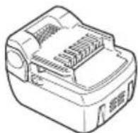
(BSL1430)
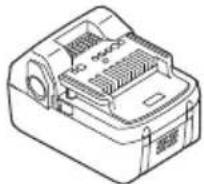
(BSL1830)
- Battery cover
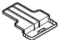
Optional accessories are subject to change without notice.
APPLICATIONS
Trimming, scaling and mowing of weed.
BATTERY REMOVAL/INSTALLATION
1. Battery removal
Hold the housing tightly and push the battery latches to remove the battery (see Fig. 2).
CAUTION
Never short-circuit the battery.
2. Battery installation
Insert the battery while observing its polarities (see Fig. 2).
CHARGING
Before using the power tool, charge the battery as follows.
- Connect the charger's power cord to a receptacle. When connecting the plug of the charger to a receptacle, the pilot lamp will blink in red (At 1-second intervals).
2. Insert the battery into the charger.
Firmly insert the battery into the charger as shown in Fig. 3 and 4 (UC18YGSL), Fig. 5 and 6 (UC18YRSL).
3. Charging
When inserting a battery in the charger, the pilot lamp will light up continuously in red. When the battery becomes fully recharged, the pilot lamp will blink in red (At 1-second intervals). (See Table 1)
(1) Pilot lamp indication
The indications of the pilot lamp will be as shown in Table 1, according to the condition of the charger or the rechargeable battery.
Table 1
| Indications of the pilot lamp (UC18YGSL) | ||||
| Pilot lamp(red) | Beforecharging | Blinks | Lights for 0.5 seconds. Does not light for 0.5 seconds. (off for 0.5 seconds) | |
| Whilecharging | Lights | Lights continuously | ||
| Chargingcomplete | Blinks | Lights for 0.5 seconds. Does not light for 0.5 seconds. (off for 0.5 seconds) | ||
| Overheatstandby | Blinks | Lights for 1 second. Does not light for 0.5 seconds. (off for 0.5 seconds) | Battery overheated.Unable to charge(Charging will commence when battery cools). | |
| Chargingimpossible | Flickers | Lights for 0.1 seconds. Does not light for 0.1 seconds. (off for 0.1 seconds) | Malfunction in the battery or the charger | |
| Indications of the pilot lamp (UC18YRSL) | ||||
| Pilot lamp(red) | Beforecharging | Blinks | Lights for 0.5 seconds. Does not light for 0.5 seconds. (off for 0.5 seconds) | |
| Whilecharging | Lights | Lights continuously | ||
| Chargingcomplete | Blinks | Lights for 0.5 seconds. Does not light for 0.5 seconds. (off for 0.5 seconds) | ||
| Chargingimpossible | Flickers | Lights for 0.1 seconds. Does not light for 0.1 seconds. (off for 0.1 seconds) | Malfunction in the battery or the charger | |
| Pilot lamp(green) | Overheatstandby | Lights | Lights continuously | Battery overheated. Unable to charge(Charging will commence when battery cools). |
(2) Regarding the temperatures of the rechargeable battery
The temperatures for rechargeable batteries are as shown in the Table 2, and batteries that have become hot should be cooled for a while before being recharged.
Table 2 Recharging ranges of batteries
| Temperatures at which the battery can be recharged |
| 0°C – 50°C |
(3) Regarding recharging time
Table 3 shows the recharging time required according to the type of battery.
Table 3 Charging time (At 20°C)
| Battery\Charger | UC18YGSL UC | 18YRSL |
| BSL1430 Approx. | 90 min. Approx. 45 | min. |
| BSL1830 Approx. | 90 min. Approx. 45 | min. |
NOTE
The recharging time may vary according to the ambient temperature.
- Disconnect the charger's power cord from the receptacle.
- Hold the charger firmly and pull out the battery.
NOTE
Be sure to pull out the battery from the charger after use, and then keep it.
Regarding electric discharge in case of new batteries, etc.
As the internal chemical substance of new batteries and batteries that have not been used for an extended period is not activated, the electric discharge might be low when using them the first and second time. This is a temporary phenomenon, and normal time required for recharging will be restored by recharging the batteries 2–3 times.
How to make the batteries perform longer
(1) Recharge the batteries before they become completely exhausted.
When you feel that the power of the tool becomes weaker, stop using the tool and recharge its battery. If you continue to use the tool and exhaust the electric current, the battery may be damaged and its life will become shorter.
(2) Avoid recharging at high temperatures.
A rechargeable battery will be hot immediately after use. If such a battery is recharged immediately after use, its internal chemical substance will deteriorate, and the battery life will be shortened. Leave the battery and recharge it after it has cooled for a while.
CAUTION
☐ If the battery is charged while it is heated because it has been left for a long time in a location subject to direct sunlight or because the battery has just been used, the pilot lamp of the charger lights for 1 second, does not light for 0.5 seconds (off for 0.5 seconds). In such a case, first let the battery cool, then start charging.
When the pilot lamp flickers (at 0.2-second intervals), check for and take out any foreign objects in the charger's battery connector. If there are no foreign objects, it is probable that the battery or charger is malfunctioning. Take it to your Center.
○ Since the built-in micro computer takes about 3 seconds to confirm that the battery being charged with UC18YGSL is taken out, wait for a minimum of 3 seconds before reinserting it to continue charging. If the battery is reinserted within 3 seconds, the battery may not be properly charged.
ABOUT POWER LAMP
The power lamp indicates various statuses for the tool. (Fig. 7)
Table 4 shows the various statuses indicated by the power lamp.
Table 4
| State of lamp Status of Tool | |
| Off | Power OFF |
| Red Power ON | |
| Blinking red | The over-heat protection circuit of the tool is operating. |
| The lever is being pressed while the overload protection circuit of the tool is operating. | |
| Quickly blinking red The tool is operating abnormally. | |
ABOUT REMAINING BATTERY INDICATOR
The remaining battery lamp blinks when the remaining battery power is low.
Please charge the tool as soon as possible. The shows the state of remaining battery indicator lamp and the battery remaining power.
Table 5
| State of lamp Battery Remaining Power | |
 | The battery remaining power is enough. |
 | The battery remaining power is nearly empty.Re-charge the battery soonest possible. |
As the remaining battery indicator shows somewhat differently depending on ambient temperature and battery characteristics, read it as a reference.
NOTE
Do not give a strong shock to the switch panel or break it. It may lead to a trouble.
PRIOR TO OPERATION
CAUTION
Pull out battery before doing any assembly.
1. Installing the loop handle (Fig. 8)
(1) Remove the M6 × 43 bolts (2 pcs.).
(2) Install the loop handle on the main pipe so that it leans against the housing.
(3) Place the handle fi xture at the lower end of the main pipe and secure it fi rmly using M6 × 43 bolts (2 pcs.) and M6 nuts (2 pcs.).
NOTEhorized Service
Secure the loop handle in a location that provides a good grip.
CAUTION
Install the loop handle properly and securely as instructed in the handling instructions.
If not attached properly or securely, it may come off and cause injury.
2. Installing cover (See Fig. 9 and 10)
WARNING
Be sure to install the cover in its designated location.
Failure to heed this warning may result in injury from fl ying stones.
NOTE
Use the supplied hex. bar wrench 4 mm for installation.
(1) Use the supplied D5 tapping screw to install the knife in the cover. (Fig. 9)
(2) Align the two holes in the cover bracket and the cover and insert two M6 × 25 hex. socket button bolts. (The cover bracket is installed in the motor case.)
(3) Place the cover holder on the underside of the cover and use the supplied hex. bar wrench 4 mm to alternately tighten the two M6 × 25 hex. socket button bolts until they are properly tightened.
CAUTION
○ Take care to avoid cutting yourself on the knife inside the cover.
○ Install the cover and knife properly and securely as instructed in the handling instructions.
If not attached properly or securely, they may come off and cause injury.
NYLON HEAD
Table 5
Installation of semi-auto nylon head
1. Function
Automatically feeds more nylon cutting line when it is tapped.
Specifications
| Code No. | Type of attaching screw | Direction of rotation | Size of attaching screw |
| 333903 | Female screw | Counterclockwise | M10×P1.25-LH |
Applicable nylon cord
Cord diameter: Φ1.4 mm
Length: 6 m
CAUTION
- The case must be securely attached to the cover.
- Check the cover, case and other components for cracks or other damage.
☐ Check the case and button for wear. If the wear limit mark on the case is no longer visible or there is a hole in the bottom of the button, change the new parts immediately. (Fig. 14)
○ The nylon head must be securely mounted to the threaded fastener of the motor case.
☐ For outstanding performance and reliability, always use HiKOKI nylon cutting line. Never use wire or other materials that could become a dangerous projectile.
☐ If the nylon head does not feed cutting line properly, check that the nylon line and all components are properly installed. Contact your HiKOKI dealer if you need assistance.
2. Installation (Fig. 11 and 12)
(1) Insert the flange assy into the motor case. At this time, the wing of the fl ange assy should face the motor case side. Next, align the holes of the fl ange assy and the motor case, insert the hex. bar wrench 4 mm, and then turn to tighten the fl ange assy.
(2) Screw the nylon head directly to the threaded fastener of the motor case.
The mounting nut of nylon head is left-hand-threaded. Turn clockwise to loosen/ counterclockwise to tighten.
CAUTION
Install the nylon head properly and securely as instructed in the handling instructions. If not attached properly or securely, it may come off and cause injury.
3. Adjustment of line length
Rotate and tap the nylon head on the ground. Nylon line is drawn out abt, 30 mm by one tapping. (Fig. 13)
Also, you can extend nylon line with hands. This time the motor must be completely stopped.
Confirm the line extends in 30 mm increments by "tapping" and "releasing" the bottom button while pulling the line ends of the nylon head. (Fig. 14)
○ Appropriate Length of Nylon Line
The appropriate length of the line when the tool is in use is 90 – 110 mm. Extend the line to the appropriate length.
4. Nylon line replacement
(1) Prepare 1.4 mm × 6 m of genuine nylon line (Code No.333923).
(2) Press the opposing tabs, and then remove the cover from the case. (Fig. 15)
(3) Remove the reel from the case. (Fig. 16)
○ If there is nylon line remaining, hook the line in the groves, and then remove the reel.
☐ If the nylon line does not extend when there is enough nylon line remaining, or when replacing the nylon line (Code No.333923), wind the nylon line using the following procedure.
(4) As shown in Fig. 17 and 18, draw the nylon line through the hole of the reel and hook it in the groove of the reel, and then wind the line in the direction of the arrow so that the nylon line does not cross.
(5) Leave about 100 mm – 150 mm nylon cord unwound, hook and secure the line in the stopper. (Fig. 19)
NOTE
Do not cross the nylon line when securing the line in the stopper. (Fig. 20)
(6) Align the position of the stopper and eyelet line guide, and then insert the button through the case.
Release the line from the stopper while holding the reel lightly, and then string the line through the eyelet line guide. (Fig. 21)
(7) Press and snap the tabs of the case in the locking holes of the cover. (Fig. 22)
WARNING
Check to make sure the tabs are firmly snapped into the locking holes.
Operating the tool while the parts are not firmly snapped together may results in accidents or injury from flying part.
(8) Pull the line taught so there is no slack, and then cut the line to an extended length of 90 mm – 110 mm with scissors. (Fig. 23)
OPERATION
Trimming grass
WARNING
○ Do not operate the tool at night or under bad weather conditions when visibility is poor.
○ Do not operate the tool when it is raining or right after it has been raining.
○ Wear proper footwear to prevent slipping that could cause you to lose your balance and fall.
○ Do not use the tool on steep slopes.
When trimming grass on slopes that are not so steep, trim by moving towards the ridge.
○ Place the right hand on the handle and the left hand on the loop handle and hold it firmly.
○ Take care not to move the nylon head too close to your feet.
○ Do not raise the nylon head above your knee during cutting.
○ Do not use the tool where the nylon head may come into contact with stones, tree and other obstacles.
○ A nylon head can injure while it continues to spin after the motor is stopped. When the unit is turned off, make sure the nylon head has stopped before the unit is set down.
☐ Do not use the tool within 15 m of another person. When you work with someone else, maintain a distance of more than 15 m.
1. Insert the battery while observing its polarities.
2. Turn on the tool. (Fig. 24)
○ Press the power button on the housing, the power goes on and the power lamp on the handle lights red.
○ Pressing the power button a second time turns the power off and the red lamp on the handle goes off.
[Auto power off]
When the power is turned on but the lever is not used for one minute, the tool is automatically turned off. To turn the tool on again, press the power button a second time.
WARNING
Never leave the tool with the power on. This could result in an accident.
3. Trimming grass
○ Grip the handle from above, press the lock lever and pull the lever to start nylon head rotation. (Fig. 25)
○ Release the lever when you finish trimming and stop the motor.
○ Place your thumb on the loop handle and grip the handle with your other fingers. (Fig. 26)
○ Take a posture that makes it easy to move.
[Grass trimming techniques]
Do not swing the pipe, but use the hips to move the nylon head horizontally from right to left in an arc while going forward and use the left side of the nylon head for cutting grass. (Fig. 27)
OPERATIONAL CAUTIONS
Continuous work
This tool comes with an over-heat protection circuit that protects the electronic parts that control the rechargeable battery. In continuous trimming work, tool temperature will rise and eventually trigger the over-heat protection circuit, which will shut down the tool.
If this happens, let the tool cool for a length of time. When the temperature drops, it will again become possible to use the tool. When the rechargeable battery has to be exchanged during continuous operation, let the tool rest for about 15 minutes.
Overload Protection
This tool comes with an overload pr to protect the electronic parts controlling the tool. In continuous overload during trimming work (locking the nylon head, etc.), the overload protection circuit shuts down the motor. If this happens, turn OFF the power, and then resolve the problem causing the overload.
The power lamp blinks if the lever is pressed after the motor has stopped (see page 59, "ABOUT POWER LAMP"). The power automatically turns OFF if the power lamp blinks longer than 5 seconds. If this happens, resolve the problem causing the overload, and then switch the power button ON to resume using the tool.
MAINTENANCE AND INSPECTION
CAUTION
Pull out battery before doing any inspection or maintenance.
1. Checking the condition of the nylon head
The nylon head should be checked regularly. If worn or broken nylon head can slip or decrease the efficiency of the motor and burn it out.
Replace worn nylon head with new ones.
CAUTION
If you use a nylon head of which point is worn or broken, it will be dangerous. So replace it with a new one.
2. Check the Screws
Loose screws are dangerous. Regularly inspect them and make sure they are tight.
CAUTION
Using this power tool with loosened screws is extremely dangerous.
3. Inspecting the carbon brushes (Fig. 28)
The motor employs carbon brushes which are consumable parts. Since and excessively worn carbon brush can result in motor trouble, replace the carbon brush with new ones when it becomes worn to or near the “wear limit”. In addition, always keep carbon brushes clean and ensure that they slide freely within the brush holders.
NOTE
When replacing the carbon brush with a new one, be sure to use the HiKOKI Carbon Brush Code No. 999015.
4. Replacing carbon brushes
Take out the carbon brush by fi rst removing the brush cap and then hooking the protrusion of the carbon brush with a slotted head screw driver, etc., as shown in Fig. 29.
When installing the carbon brush, choose the direction so that the nail of the carbon brush (see Fig. 30) agrees with the contact portion of brush tube. Then push it in with a finger as illustrated in Fig. 31. Lastly, install the brush cap.
CAUTION
☐ Be absolutely sure to insert the nail of the carbon brush into the contact portion of brush tube. (You can insert whichever one of the two nails provided.)
○ Caution must be exercised since any error in this operation can result in the deformed nail of the carbon brush and may cause motor trouble at an early stage.
5. Cleaning of the outside
When the grass trimmer is stained, wipe with a soft dry cloth or a cloth moistened with soapy water. Do not use chloric solvents, gasoline or paint thinner, as they melt plastics.
6. Storage
Store grass trimmer in a place in which the temperature is less than 40^ C and out of reach of children.
Make sure that the battery is fully charged when stored for a long period (3 months or more). The battery with smaller capacity may not be able to be charged when used, if stored for a long period.
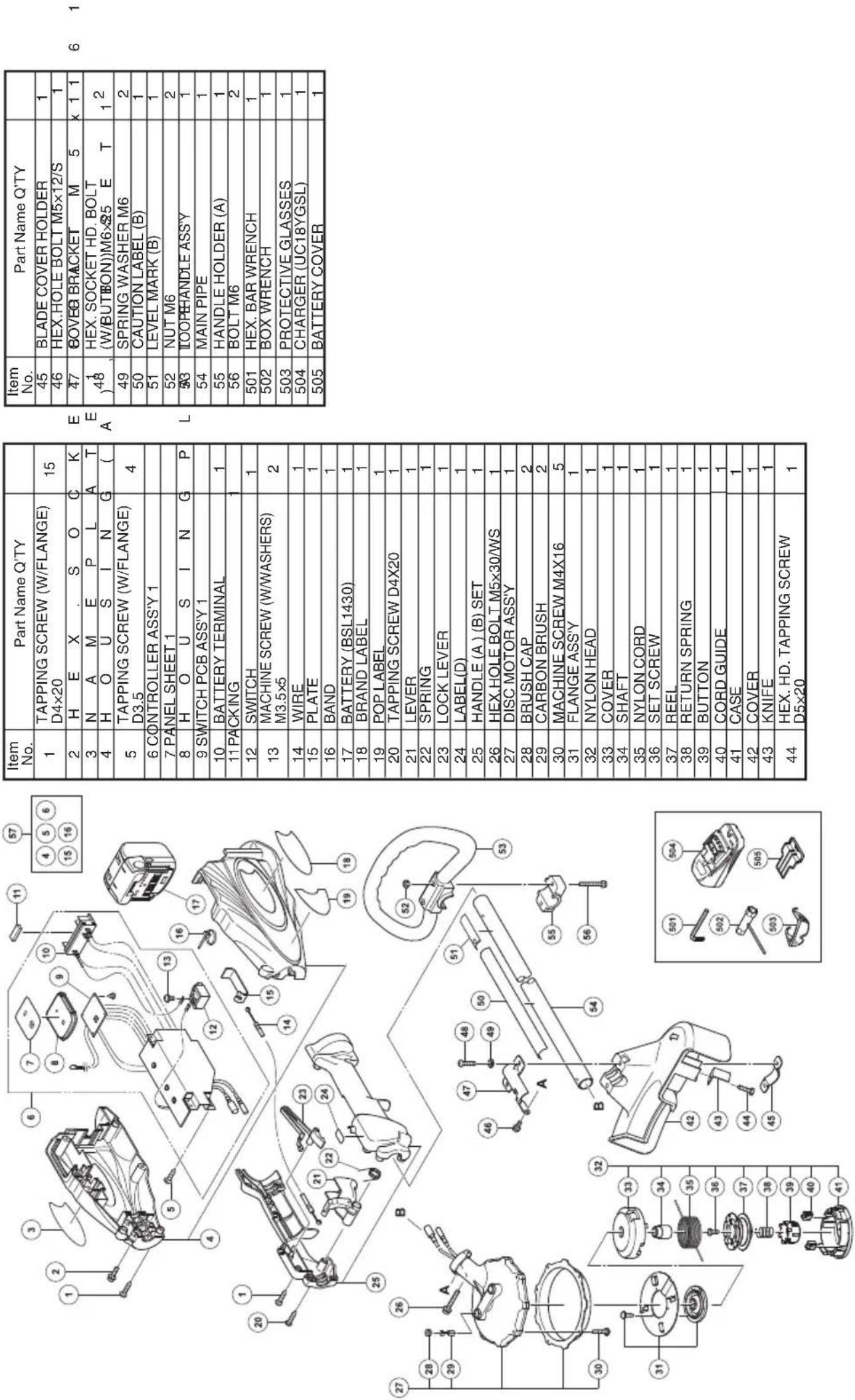
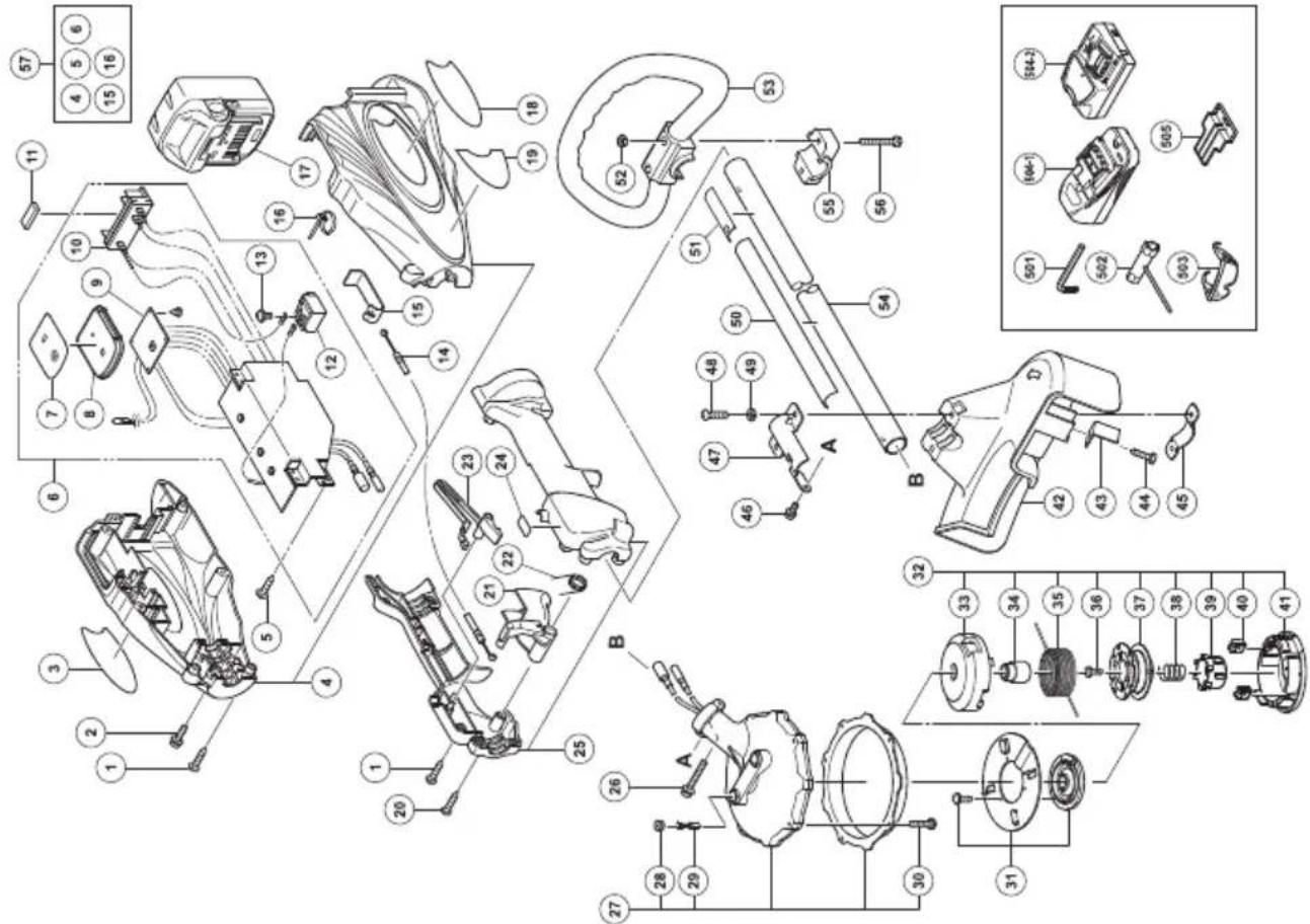
7. Service parts list
CAUTION
Repair, modification and inspection of HiKOKI Power Tools must be carried out by a HiKOKI Authorized Service Center.
This Parts List will be helpful if presented with the tool to the HiKOKI Authorized Service Center when requesting repair or other maintenance.
In the operation and maintenance of power tools, the safety regulations and standards prescribed in each country must be observed.
MODIFICATIONS
HiKOKI Power Tools are constantly being improved and modified to incorporate the latest technological advancements.
Accordingly, some parts may be changed without prior notice.
Important notice on the batteries for the HiKOKI cordless power tools
Please always use one of our designated genuine batteries. We cannot guarantee the safety and performance of our cordless power tool when used with batteries other than these designated by us, or when the battery is disassembled and modified (such as disassembly and replacement of cells or other internal parts).
TROUBLESHOOTING
Use the inspections in the table below if the tool does not operate normally. If this does not remedy the problem, consult your dealer or the HiKOKI Authorized Service Center.
| Symptom Possible cause Remedy | |||
| Charger The Charge lamp does not go on. | The power plug is not connected to an AC outlet. | Connect the power plug to an AC outlet. | |
| The battery is not properly connected to the charger. | Insert the battery so that it is properly seated in the charger. | ||
| The battery or charger electrodes are soiled. | Use a cotton swab or other tool to clean the electrodes. | ||
| The battery is extremely hot. Allow the battery to properly cool before charging. | |||
| The charge lamp does not go off after 4 hours of charging. | The battery or charger is faulty. Disconnect the power plug and consult your dealer or the HiKOKI Authorized Service Center. | ||
| Tool Does not operate. The rechargeable battery is depleted. Charge the rechargeable battery. | |||
NOTE
Due to HiKOKI's continuing program of research and development, the specifications herein are subject to change without prior notice.
Information concerning airborne noise and vibration
The measured values were determined according to IEC60335 and declared in accordance with ISO 4871.
Measured A-weighted sound power level: 75 dB (A). Measured A-weighted sound pressure level: 66 dB (A). Uncertainty KpA: 3 dB (A).
Wear hearing protection.
Vibration total values (triax vector sum) determined according to IEC60335.
Vibration emission value ah. w = 1.8 m/s²
The declared vibration total value has been measured in accordance with a standard test method and may be used for comparing one tool with another.
It may also be used in a preliminary assessment of exposure.
WARNING
☐ The vibration emission during actual use of the power tool can differ from the declared total value depending on the ways in which the tool is used.
○ Identify safety measures to protect the operator that are based on an estimation of exposure in the actual conditions of use (taking account of all parts of the operating cycle such as the times when the tool is switched off and when it is running idle in addition to the trigger time).
CG14DSL
| Item No. | Part Name Q'TY | |
| 45 | BLADE COVER HOLDER | 1 |
| 46 | HEX.HOLE BOLT M5x12/S | 1 |
| 47 | ∅BOVE BRACKET M 5 x 1 1 | |
| 48 | HEX. SOCKET HD. BOLT(W/BUTBON))M6×25 E T | 1 2 |
| 49 | SPRING WASHER M6 | 2 |
| 50 | CAUTION LABEL (B) | 1 |
| 51 | LEVEL MARK (B) | 1 |
| 52 | NUT M6 | 2 |
| 33 | IOOPHANDLE ASSY | 1 |
| 54 | MAIN PIPE | 1 |
| 55 | HANDLE HOLDER (A) | 1 |
| 56 | BOLT M6 | 2 |
| 501 | HEX. BAR WRENCH | 1 |
| 502 | BOX WRENCH | 1 |
| 503 | PROTECTIVE GLASSES | 1 |
| 504 | CHARGER (UC18YGSL) | 1 |
| 505 | BATTERY COVER | 1 |
| Item No. | Part Name Q'TY | |
| 1 | TAPPING SCREW (W/FLANGE) D4x20 | 15 |
| 2 | H E X . S O C K | |
| 3 | N A M E P L A T | |
| 4 | H O U S I N G ( | |
| 5 | TAPPING SCREW (W/FLANGE) D3.5 | 4 |
| 6 | CONTROLLER ASS'Y 1 | |
| 7 | PANEL SHEET 1 | |
| 8 | H O U S I N G P | |
| 9 | SWITCH PCB ASS'Y 1 | |
| 10 | BATTERY TERMINAL | 1 |
| 11 | PACKING | 1 |
| 12 | SWITCH | 1 |
| 13 | MACHINE SCREW (W/WASHERS) M3.5x5 | 2 |
| 14 | WIRE | 1 |
| 15 | PLATE | 1 |
| 16 | BAND | 1 |
| 17 | BATTERY (BSL1430) | 1 |
| 18 | BRAND LABEL | 1 |
| 19 | POP LABEL | 1 |
| 20 | TAPPING SCREW D4X20 | 1 |
| 21 | LEVER | 1 |
| 22 | SPRING | 1 |
| 23 | LOCK LEVER | 1 |
| 24 | LABEL(D) | 1 |
| 25 | HANDLE (A) (B) SET | 1 |
| 26 | HEX HOLE BOLT M5x30/WS | 1 |
| 27 | DISC MOTOR ASS'Y | 1 |
| 28 | BRUSH CAP | 2 |
| 29 | CARBON BRUSH | 2 |
| 30 | MACHINE SCREW M4X16 | 5 |
| 31 | FLANGE ASS'Y | 1 |
| 32 | NYLON HEAD | 1 |
| 33 | COVER | 1 |
| 34 | SHAFT | 1 |
| 35 | NYLON CORD | 1 |
| 36 | SET SCREW | 1 |
| 37 | REEL | 1 |
| 38 | RETURN SPRING | 1 |
| 39 | BUTTON | 1 |
| 40 | CORD GUIDE | 1 |
| 41 | CASE | 1 |
| 42 | COVER | 1 |
| 43 | KNIFE | 1 |
| 44 | HEX, HD, TAPPING SCREW D5x20 | 1 |
CG18DSDL
| Item No. | Part Name Q'TY | |
| 45 | BLADE COVER HOLDER | 1 |
| 46 | HEX.HOLE BOLT M5×12/S | 1 |
| 47 | COVER BRACKET M 5 × 1 1 | |
| 48 | HEX. SOCKET HD. BOLT(W(BUTBON)) M6×25 E T | 1 2 |
| 49 | SPRING WASHER M6 | 2 |
| 50 | CAUTION LABEL (B) | 1 |
| 51 | LEVEL MARK (B) | 1 |
| 52 | NUT M6 | 2 |
| 53 | LOORHANDLE ASS'Y | 1 |
| 54 | MAIN PIPE | 1 |
| 55 | HANDLE HOLDER (A) | 1 |
| 56 | BOLT M6 | 2 |
| 501 | HEX. BAR WRENCH | 1 |
| 502 | BOX WRENCH | 1 |
| 503 | PROTECTIVE GLASSES | 1 |
| 504-1 | CHARGER (UC18YGSL) | 1 |
| 504-2 | CHARGER (UC18YRSL) | 1 |
| 505 | BATTERY COVER | 1 |
E E A
| Item No. | Part Name Q'TY | |
| 1 | TAPPING SCREW (W/FLANGE) D4×20 | 15 |
| 2 | H E X . S O C K | |
| 3 | N A M E P L A T | |
| 4 | H O U S I N G ( | |
| 5 | TAPPING SCREW (W/FLANGE) D3.5 | 4 |
| 6 CONTROLLER ASS'Y 1 | ||
| 7 PANEL SHEET 1 | ||
| 8 | H O U S I N G P | |
| 9 SWITCH PCB ASS'Y 1 | ||
| 10 | BATTERY TERMINAL | 1 |
| 11 PACKING 1 | ||
| 12 | SWITCH | 1 |
| 13 | MACHINE SCREW (W/WASHERS) M3.5×5 | 2 |
| 14 | WIRE | 1 |
| 15 | PLATE | 1 |
| 16 | BAND | 1 |
| 17 | BATTERY (BSL1830) | 1 |
| 18 | BRAND LABEL | 1 |
| 19 | POP LABEL | 1 |
| 20 | TAPPING SCREW D4×20 | 1 |
| 21 | LEVER | 1 |
| 22 | SPRING | 1 |
| 23 | LOCK LEVER | 1 |
| 24 | LABEL(D) | 1 |
| 25 | HANDLE (A ) (B) SET | 1 |
| 26 | HEX.HOLE BOLT M5×30/WS | 1 |
| 27 | DISC MOTOR ASS'Y | 1 |
| 28 | BRUSH CAP | 2 |
| 29 | CARBON BRUSH | 2 |
| 30 | MACHINE SCREW M4X16 | 5 |
| 31 | FLANGE ASS'Y | 1 |
| 32 | NYLON HEAD | 1 |
| 33 | COVER | 1 |
| 34 | SHAFT | 1 |
| 35 | NYLON CORD | 1 |
| 36 | SET SCREW | 1 |
| 37 | REEL | 1 |
| 38 | RETURN SPRING | 1 |
| 39 | BUTTON | 1 |
| 40 | CORD GUIDE | 1 |
| 41 | CASE | 1 |
| 42 | COVER | 1 |
| 43 | KNIFE | 1 |
| 44 | HEX. HD. TAPPING SCREW D5×20 | 1 |
Hikoki Power Tools Norway AS
Kjeller Vest 7, N-2007 Kjeller, Norway
Tel: (+47) 6692 6600
Fax: (+47) 6692 6650
URL: http://www.hikoki-powertools.no
Hikoki Power Tools Sweden AB
Rotebergsvagen 2B SE-192 78 Sollentuna, Sweden
Tel: (+46) 8 598 999 00
Fax: (+46) 8 598 999 40
URL: http://www.hikoki-powertools.se
Hikoki Power Tools Denmark A/S
Lillebaeltsvej 90, 6715 Esbjerg N, Denmark
Tel: (+45) 75 14 32 00
Fax: (+45) 75 14 36 66
URL: http://www.hikoki-powertools.dk
Hikoki Power Tools Finland Oy
Tupalankatu 9, 15680 Lahti, Finland
Tel: (+358) 20 7431 530
Fax: (+358) 20 7431 531
URL: http://www.hikoki-powertools.fi
natural_image
Line drawing of a quill pen in an inkwell (no text or symbols)| Svenska Suomi | |||
| EG-DEKLARATION BETRÄFFANDE LIKFORMIGHETVi förklarar på eget ansvar att produkten batteridriven grästrimmer identifierad enligt typ och särskild identifikationskod *1), överensstämmer med alla relevanta krav i direktiven *2) och standarderna *3). Teknisk fi i enligt *4) – Se nedan.Den europeiska standardansvariga på representationskontoret i Europa är auktoriserad att sammanstålia den tekniska fi len.2000/14/EGTyp av utrustning: GrästrimmerTypnamn: CG14DSDL, CG18DSDLSkärbredd: 31 cm (1 kabel), 31 cm (2 kabler)Konformitetsbedömningsmetod: Annex VIUnderrättat europeiskt organ: CE 0044 TÜV NORD CERT Am TÜV 1, 30519 Hannover, TysklandUppmätt ljudstyrkenivå (1 kabel): 76 dBUppmätt ljudstyrkenivå (2 kabler): 81 dBGaranterad ljudstyrkenivå: 88 dBDenna försåkran gäller för produkten med tillhörande CE-märkning. | EY-ILMOITUS YHDENMUKAISUUDESTAVakuutamme yksinomaisella vastuullämme, että akutoiminen ruohikon viimeisteljä, joka identifioidaan tyypin ja erityisen tunnistuskoodin *1) perusteella, on kaikkien direktivien *2) ja standardien *3) asiaankuuluvien vaatimusten mukainen. Tekninen tiedosto kohdassa *4) – katso alta.Euroopalaisten standardien hallintaelin Euroopan edustustossa on valltuutettu kokoamaan teknisen tiedoston.2000/14/EYLaitteen tyyppi: Nurmikon viimeisteljäTyppinimi: CG14DSDL, CG18DSDLEikkausleveys: 31 cm (1 naru), 31 cm (2 narua)Yhdenmukaisuuden määritystolmenpiteet: Annex VIImoitettu elin Euroopassa: CE 0044 TÜV NORD CERT Am TÜV 1, 30519 Hannover, GermanyMitattu äänenpainetaso (1 naru): 76 dBMitattu äänenpainetaso (2 narua): 81 dBTaattu äämempanetaso: 88 dBIlmoitus on sovellettavissa tuotteeseen kiinnitettyyn CE-merkintään. | ||
| Dansk English | |||
| EF-OVERENSSTEMMELSESERKLÆRINGVi erklærer os fuldstændigt ansvarlige for, at Akku græstrimmeren, identificeret ved type og specifik identifikationskode *1), er i overensstemmelse med alle relevante krav i direktiverne *2) og standarderne *3). Teknisk fi i *4) – Se nedenfor.Lederen af europeiske standarder på repræsentationskontoret i Europa er bemyndiget til at kompilere den tekniske fi I.2000/14/EEUdstyrstype: PlænetrimmerTypenavn: CG14DSDL, CG18DSDLLkippebredde: 31 cm (1 kabel), 31 cm (2 kabler)Procedure for fastsættelse af ensartethed: Bilag VIIAnmeldt europæisk organisation: CE 0044 TÜV NORD CERT Am TÜV 1, 30519, Hannover, TysklandMålt lydstyrkeniveau (1 kabel): 76 dBMålt lydstyrkeniveau (2 kabler): 81 dBGaranteret lydstyrkeniveau: 88 dERklæringen gjelder produktet, der er mærket med CE. | EC DECLARATION OF CONFORMITYWe declare under our sole responsibility that Cordless Grass Trimmer, identified by type and specific identification code *1), is in conformity with all relevant requirements of the directives *2) and standards *3). Technical fi le at *4) – See below.The European Standard Manager at the representative office in Europe is authorized to compile the technical fi le.2000/14/ECType of equipment: Lawn TrimmerType name: CG14DSDL, CG18DSDLCutting width: 31 cm (1 cord), 31 cm (2 cords)Conformity assessment procedure: Annex VIEuropean Notified Body: CE 0044 TÜV NORD CERT Am TÜV 1, 30519 Hannover, GermanyMeasured sound power level (1 cord): 76 dBMeasured sound power level (2 cords): 81 dBGuaranteed sound power level: 88 dBThe declaration is applicable to the product affi xed CE marking. | ||
| Norsk | EF'S ERKLÆRING OM OVERENSSTEMMELSEVi erklærer på eget ansvar at batteri grestrimmer, identifisert etter type og spesifikk identifikasjonskode *1), er i samsvar med alle relevante krav i direktiver *2) og standarder *3). Teknisk fi under *4) - Se nedenfor.Styreren for europeiske standarder ved representantkontoret i Europa er autorisert til å kompilere den tekniske fi len.2000/14/EEUdstyrstype: PlenklipperTypenavn: CG14DSDL, CG18DSDLLuttebredde: 31 cm (1 kabel), 31 cm (2 kabler)Prosedyre for konformitetsvurdering: Annex VIEuropeisk underrettet organ: CE 0044 TÜV NORD CERT Am TÜV 1, 30519 Hannover, TysklandMålt lydelf ektnivå (1 kabel): 76 dBMålt lydelf ektnivå (2 kabler): 81 dBGaranteret lydelf ektnivå: 88 dERklæringen gjelder for CE-merket på produktet. | ||
| *1) CG18DSDL C342899S*2) 2006/42/EC, 2000/14/EC, 2014/30/EU, 2014/35/EU, 2011/65/EU*3) EN60335-1:2012+A11:2014EN50636-2-91:2014EN60335-2-29:2004+A2:2010EN55014-1:2006+A1:2009+A2:2011EN55014-2:1997+A1:2001+A2:2008 | |||
| *4) Representative office in EuropeHikoki Power Tools Deutschland GmbHSiemensring 34, 47877 Willich, GermanyHead offi ce in JapanKoki Holdings Co., Ltd.Shinagawa Intercity Tower A, 15-1, Konan 2-chome,Minato-ku, Tokyo, Japan | 29. 6. 2018Naoto YamashiroEuropean Standard Manager29. 6. 2018A. NakagawaCorporate Offi cer | ||
Koki Holdings Co., Ltd.
- ALLMÄNNA SÄKERHETSVARNINGAR FÖR ELEKTRISKA VERKTYG
- WARNING
- VEDLIKEHOLD OG INSPEKSJON
- FORSIKTIG
- Save all warnings and instructions for future reference.
- 1) Work area safety
- 2) Electrical safety
- 3) Personal safety
- 4) Power tool use and care
- PRECAUTION
- GRASS TRIMMER SAFETY WARNINGS
- IMPORTANT
- READ CAREFULLY BEFORE USE
- KEEP FOR FUTURE REFERENCE
- Safe operation practices
- ● Training
- ● Preparation
- Operation
- ● Maintenance and storage
- PRECAUTIONS FOR CORDLESS GRASS TRIMMER
- CAUTION
- PRECAUTIONS FOR BATTERY AND CHARGER
- CAUTION ON LITHIUM-ION BATTERY
- SPECIFICATIONS
- OPTIONAL ACCESSORIES (sold separately)
- APPLICATIONS
- BATTERY REMOVAL/INSTALLATION
- Battery removal
- Battery installation
- CHARGING
- Insert the battery into the charger.
- Charging
- Pilot lamp indication
- NOTE
- Regarding electric discharge in case of new batteries, etc.
- How to make the batteries perform longer
- ABOUT POWER LAMP
- ABOUT REMAINING BATTERY INDICATOR
- PRIOR TO OPERATION
- Installing the loop handle (Fig. 8)
- Installing cover (See Fig. 9 and 10)
- NYLON HEAD
- Table 5
- Installation of semi-auto nylon head
- Function
- Installation (Fig. 11 and 12)
- Adjustment of line length
- Nylon line replacement
- Trimming grass
- Insert the battery while observing its polarities.
- Turn on the tool. (Fig. 24)
- [Auto power off]
- Trimming grass
- [Grass trimming techniques]
- OPERATIONAL CAUTIONS
- Continuous work
- Overload Protection
- MAINTENANCE AND INSPECTION
- Checking the condition of the nylon head
- Check the Screws
- Inspecting the carbon brushes (Fig. 28)
- Replacing carbon brushes
- Cleaning of the outside
- Storage
- Service parts list
- MODIFICATIONS
- Important notice on the batteries for the HiKOKI cordless power tools
- TROUBLESHOOTING
- Information concerning airborne noise and vibration
- Hikoki Power Tools Norway AS
- Hikoki Power Tools Sweden AB
- Hikoki Power Tools Denmark A/S
- Hikoki Power Tools Finland Oy
- Koki Holdings Co., Ltd.
Brand : HiKOKI
Model : CG 14DSDL
Category : Brush cutter