
DV 10DVA - Drill HITACHI - Free user manual and instructions
Find the device manual for free DV 10DVA HITACHI in PDF.


| Product Type | Corded Drill |
| Brand | Hitachi |
| Model | DV 10DVA |
| Drilling Capacity (Steel) | 10 mm (3/8") |
| Drilling Capacity (Wood) | 25 mm (1") |
| Power Input | 500 W |
| No-Load Speed | 0 - 2,800 rpm |
| Variable Speed | Yes |
| Reverse Function | Yes |
| Chuck Type | Keyless Chuck |
| Chuck Size | 1.5 - 10 mm |
| Power Supply | AC 220-240 V, 50/60 Hz |
| Net Weight | 1.4 kg (3.1 lbs) |
| Dimensions (L x W x H) | 250 x 65 x 200 mm |
| Cable Length | 2.5 m |
| Vibration Level | < 2.5 m/s² |
| Sound Pressure Level | 85 dB(A) |
| Safety Features | Lock-on button, insulated housing |
| Maintenance | Clean ventilation slots, lubricate chuck |
| Spare Parts Available | Carbon brushes, chuck, switch |
Frequently Asked Questions - DV 10DVA HITACHI
User questions about DV 10DVA HITACHI
0 question about this device. Answer the ones you know or ask your own.
Ask a new question about this device
Download the instructions for your Drill in PDF format for free! Find your manual DV 10DVA - HITACHI and take your electronic device back in hand. On this page are published all the documents necessary for the use of your device. DV 10DVA by HITACHI.
USER MANUAL DV 10DVA HITACHI
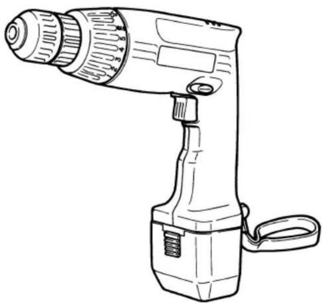
BATTERIDRIVEN SLAGBORR BATTERIDREVET SLAGBOREMASKINE BATTERIDREVET SLAGBOREMASKIN PARISTOKÄYTTÖINEN ISKUPORA CORDLESS IMPACT DRILL
Variable speed
DV 10DVA
natural_image
Line drawing of a handheld electric drill with handle and control knob (no text or symbols)Read through carefully and understand these instructions before use.
Bruksanvisning
Brugsanvisning
Bruksanvisning
Käyttöohjeet
Handling Instructions
| Item No. | Part Name |
| 1 | Name Plate |
| 2 | Housing (A) • (B) Set |
| 3 | Tapping screw (W/Flange) D3- 18 |
| 4 | Pushing Button |
| 5 | Strap |
| 6 | Flat Hd. Screw (Left Hand) M5- 20 |
| 7 | Drill Chuck 10VLR-N |
| 8 | Cap |
| 9 | O-Ring |
| 10 | O-Ring Plate |
| 11 | Clutch Plate |
| 12 | Spring |
| 13 | Spring Holder |
| 14 | Steel Ball |
| 15 | Spindle Gear |
| 16 | Shift Arm |
| 17 | Shift Knob |
| 18 | Motor |
| 19 | Machine Screw M3- 4 |
| 20 | Fin |
| 21 | Machine Screw M2- 7 |
| 22 | Tapping Screw D3- 14 |
| 23 | DC-Speed Control Switch |
| 24 | Terminal Support |
| 25 | HITACHI Label |
| 26 | Mark Plate |
| 27 | Battery EB12 |
| 501 | Charger (Model UC12SC) |
| 502 | Case |
Parts are subject to possible modification without notice due to improvements

1

2
3

4

5

6
7

8

natural_image
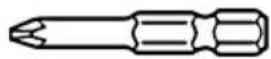
Technical line drawing of a mechanical connector or fitting (no text or symbols)- Krysskruvdragarspets
| Spets Nr. | Skruvstorlek |
| No 2 | 3 - 5 mm |
natural_image
Technical line drawing of a mechanical connector or fitting (no text or symbols)natural_image
Technical line drawing of a mechanical connector or fitting (no text or symbols)- Plussbits
VEDLIKEHOLD OG INSPEKSJON
natural_image
Technical line drawing of a mechanical connector or fitting (no text or symbols)- Keep work area clean. Cluttered areas and benches invite accidents.
- Avoid dangerous environment. Don't expose power tools and charger to rain. Don't use power tools and charger in damp or wet locations. And keep work area well lit.
Never use power tools and charger near flammable or explosive materials.
Do not use tool and charger in presence of flammable liquids or gases. - Keep children away. All visitors should be kept safe distance from work area.
- Store idle tools and charger. When not in use, tools and charger should be stored in dry, high or locked-up place-out of reach of children. Store tools and charger in a place where the temperature is less than 40^ C.
- Don't force tool. It will do the job better and safer at the rate for which it was designed.
- Use right tool. Don't force small tool or attachment to do the job of a heavy duty tool.
- Wear proper apparel. No loose clothing or jewelry to get caught in moving parts. Rubber gloves and footwear are recommended when working outdoor.
- Use safety glasses with most tools. Also face or dust mask if cutting operation is dusty.
- Don't abuse cord. Never carry charger by cord or yank it to disconnect from receptacle. Keep cord from heat, oil and sharp edges.
- Secure work. Use clamps or a vise to hold work. It's safer than using your hand and it frees both hands to operate tool.
- Don't overreach. Keep proper footing and balance at all times.
- Maintain tools with care. Keep tools sharp at all times, and clean for best and safest performance. Follow instructions for lubricating and changing accessories.
- When the charger is not in use, or when being maintained and inspected, disconnect the power cord of the charger from the AC outlet.
- Remove chuck wrenches and wrenches. Form habit of checking to see that wrenches are removed from tool before turning it on.
- Avoid accidental starting. Don't carry tool with finger on switch.
- Always use the specified charger. Never use a charger other than that specified to prevent danger.
- Use only original HITACHI replacement parts.
- Do not use power tools for applications other than those specified in the Handling Instructions.
- To ensure the designed operational integrity of power tools and charger, do not remove installed covers or screws.
- Consult an authorized Service Agent in the event of power tool and charger failure.
- Always use the charger at the voltage specified on the nameplate.
- Do not touch movable parts or accessories unless the battery has been removed.
- Always charge the battery before use.
- Never use a battery other than that specified. Do
not connect a usual dry cell, a rechargeable battery other than that specified or a car battery to the power tool.
25. Do not use any transformer that has a booster.
26. Do not charge the battery from an engine electric generator or DC power supply.
27. Always charge indoors. Because the charger and battery heat slightly during charging, charge the battery in a place not exposed to direct sunlight; which has low humidity and is well ventilated.
28. When working in a high place, pay attention to the activities below to make sure there are no people below.
PRECAUTIONS FOR CORDLESS IMPACT DRILL
- Always charge the battery at a temperature of 10 - 40°C. A temperature of less than 10°C will result in over charging which is dangerous. The battery cannot be charged at a temperature higher than 40°C. The most suitable temperature for charging is that of 20 - 25°C.
- Do not use the charger continuously. When one charging is completed, leave the charger for about 15 minutes before the next charging of battery.
- Do not charge the battery for more than 2 hour. The battery will be fully charged in about 1 hour and charging should be stopped when 1 hour has elapsed from commencement. Disconnect the charger power cord from the AC outlet.
- Do not allow foreign matter to enter the hole for connecting the rechargeable battery.
- Never disassemble the rechargeable battery and charger.
- Never short-circuit the rechargeable battery. Short-circuiting the battery will cause a great electric current and overheat. It results in burn or damage to the battery.
- Do not dispose of the battery in fire. If the battery is burnt, it may explode.
- When drilling into wall, floor or ceiling, check for buried electric power cable, gas pipe, etc.
- Bring the battery to the shop from which it was purchased as soon as the post-charging battery life becomes too short for practical use. Do not dispose of the exhausted battery.
- Using an exhausted battery will damage the charger.
- Do not insert foreign object into the air ventilation slots of the charger. Inserting metal objects or inflammables into the charger air ventilation slots will result in electrical shock hazard or damaged charger.
- When mounting a bit into the keyless chuck, tighten the sleeve securely. If the sleeve is not tight, the bit may slip or come off, causing injury.
SPECIFICATIONS
POWER TOOL
| Model DV10DVA | |||
| No-load speed (Low/High) 0 – 350/0 | -1100/min. | ||
| No-load impact rate (Low/High) 0 – | 6300/0 – 19800/min. | ||
| Capacity | Drilling | Brick 10 mm | |
| Wood 18 mm | |||
| Metal Steel: 10 mm, Aluminum: 10 mm | |||
| Driving | Machine screw 6 mm | ||
| Wood screw 5.1 mm (diameter) x 32 mm (length) (There is a pilot hole) | |||
| Rechargeable battery (EB12) Ni-Cd | battery, 12 V | ||
| Weight 1.9 kg | |||
CHARGER
| Model | UC12SC |
| Charging time | Approx. 1 hour (at 20°C) |
| Charging voltage | 12 V |
| Weight | 1.4 kg |
STANDARD ACCESSORIES
| DV10DVA |   1 Charger (UC12SC)....12 Plastic case....1 1 Charger (UC12SC)....12 Plastic case....1 |
Standard accessories are subject to change without notice.
OPTIONAL ACCESSORIES .....(sold separately)
- Battery (EB12)

natural_image
Technical line drawing of a mechanical component with threaded end and flange (no text or symbols)- Plus driver bit
| Bit No. | Screw size |
| No. 2 | 3 - 5 mm |

English
3. Minus driver bit
| a Screw size | |
| 0.8 mm 4 mm |

4. Hexagon socket (for nuts and bolts)
| Socket No. Screw size | |
| 7 | 4 |
| 8 | 5 |
| 10 6 mm | |

5. Drill bit for brick
Diameter, 6.5 mm, 8 mm, 9.5 mm, 10 mm
Optional accessories are subject to change without notice.
APPLICATIONS
○Drilling of brick and concrete block, etc.
○Driving and removing of machine screws, wood screws, tapping screws, etc.
○Drilling of various metals.
○Drilling of various woods.
BATTERY REMOVAL/INSTALLATION
1. Battery removal
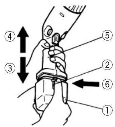
Hold the handle tightly and push the battery latch to remove the battery (see Figs. 1 and 2).
CAUTION
Never short-circuit the battery.
2. Battery installation
Insert the battery while observing its polarities (see Fig. 2).
CHARGING
Before using the impact drill, charge the battery as follows.
-
Insert the battery in the charger. Position the battery so that the nameplate faces toward the nameplate of the charger and press in the battery until it comes into contact with the bottom plate. (See Figs. 1 and 3.)
-
Connect the charger power cord to the AC outlet. Connecting the power cord will turn on the charger (the pilot lamp lights up).
CAUTION
If the pilot lamp does not light up, pull out the power cord from the AC outlet and check the battery mounting condition.
About 1 hour is required to fully charge the battery at a temperature of about 20°C. The pilot lamp goes off to indicate that the battery is fully charged.
NOTE
The charging time may very depending on the ambient temperature and input power supply voltage conditions.
The example of the relationship between the input power supply voltage and the charging time is shown in Fig 9.
The charging time decreases if the ambient temperature and input power supply voltage are high and increases when they are low.
(Minutes)

line
| Input Power Supply Voltage | Charging Time (m) at 10°C | Charging Time (m) at 20°C | | -------------------------- | ------------------------ | ------------------------ | | 0 | 100 | 100 | | Rated Voltage (Voltage Listed on Nameplate) | ~85 | ~70 | | 105% of Rated Voltage | ~55 | ~50 |Fig.9 Relationship Between Input Power Supply Voltage and Charging Time
CAUTION
If the battery is heated due to direct sunlight, etc., just after operation, the charger pilot lamp may not light. At that time cool the battery first, then start charging.
- Disconnect the charger power cord from the AC outlet.
- Hold the charger tight and pull out the battery.
PRIOR TO OPERATION
1. Setting up and checking the work environment
Check if the work environment is suitable by following the precautions.
HOW TO USE
1. Confirm the cap position
The three modes of screwdriver, drill and impact drill can be switched by the position of the cap in this tool.
(1) When the tool is used as a screwdriver, align the number displayed on the cap from "1" to "5" to the triangle mark of the housing.
(2) When the tool is used as a drill, align the drill mark "###" displayed on the cap to the triangle mark of the housing.
(3) When the tool is used as the impact drill, align the hammer mark "T" displayed on the cap to the triangle mark of the housing. (See Fig. 4.)
CAUTION
Align the number and mark on the cap to the triangle mark of the housing. The middle point of the numbers and marks on the cap cannot be secured.
2. Tightening torque adjustment
(1) Tightening torque
Tightening torque should correspond in its intensity to the screw diameter. When too strong power is used, the screw head may be broken or be injured. Be sure to adjust the cap position according to the screw diameter.
(2) Tightening torque indication
Tightening torque should be changed according to the screw type and the materials to be tightened. Guidance of the tightening torque is indicated on the cap of this unit with numerals “1”, “2”, “3”, “4” and “5”. The minimum power is from “1” position and bigger the value the stronger is the power (see Fig. 4).
(3) How to adjust the tightening torque
Rotate the cap and set to one of the numerals.
Adjust the torque by cap rotation in such a way that when the torque is too strong, set to the next smaller numeral and set to the next larger numeral when too weak.
CAUTIONS
○The motor rotation may be locked to cease while the unit is used as drill. While operating the impact drill, take care not to lock the motor.
☐Too long hammering may cause the screw broken due to excessive tightening.
- Rotation to Impact changeover (See Fig. 4.).
The "Rotation (Rotation only)" and "Impact (Impact + Rotation)" can be switched by aligning the drill
mark "dor the hammer mark" " to the triangle mark of the housing.
To make holes in the metal, wood or plastic, switch to "Rotation (Rotation only)".
○To make holes in bricks or concrete blocks, switch to "Impact (Impact + Rotation)".
CAUTION
If an operation which is normally performed at the "Rotation" setting is performed at "Impact" setting, the effect of making holes does not only increase but it may also damage the bit or other parts.
4. Change rotation speed
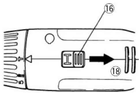
Operate the shift knob to change the rotational speed. Move the shift knob in the direction of the arrow (see Figs. 5 and 6).
When the shift knob is set to “L”, the drill rotates at a low speed. When set to “H”, the drill rotates at a high speed.
CAUTION
When changing the rotational speed with the shift knob, confirm that the switch is off.
Changing the speed while the motor is rotating will damage the gears.
When setting the shift knob to "H" (high speed) and the position of the cap is "4" or "5", it may happen that the clutch does not engage and that the motor is locked. In such a case, please set the shift knob to "L" (low speed).
○If the motor is locked, immediately turn the power off. If the motor is locked for a while, the motor or battery may be burnt.
5. The scope and suggestions for uses
The usable scope for various types of work based on the mechanical structure of this unit is shown
Table 1
| Work Usable range Suggestions | ||
| Drilling | Brick: 10 mm | Use for drilling purpose. |
| Wood: 18 mm | ||
| Steel: 10 mm | ||
| Aluminum: 10 mm | ||
| Driving | Machine screw: 6 mm | Use the bit and socket matching the screw diameter. |
| Nut: 5 mm | ||
| Wood screw: 5.1 mm (diameter) x 32 mm (length) Use after drilling a pilot hole. | ||
6. How to select tightening power and rotational speed
Table 2
| Use Cap Position | Rotating speed selection (Position of the shift knob) | |||
| L (Low speed) H (High speed) | ||||
| Driving | Machine screw 1 – 5 | For 4 mm or smaller diameter screws. | For 5 mm or larger diameter screws. | |
| Wood screw 1 – 5 For 3.5 mm or smaller nominal diameter screws. | For 3.8 mm or larger nominal diameter screws. | |||
| Drilling | Brick —— | For drilling with a carbide tipped drill bit. | ||
| Wood For 10 mm or larger diameters. | For 10 mm or smaller diameters. | |||
| Metal | For drilling with a metal working drill bit. | —— | ||
CAUTION
☐ The selection examples shown in Table 2 should be considered as general standard. As different types of tightening screws and different materials to be tightened are used in actual works proper adjustments are naturally necessary.
7. Mounting and dismounting of the bit.
(1) Mounting the bit
After inserting a driver bit, etc. into the keyless drill chuck, firmly grasp the ring and tighten the sleeve by turning it toward the right (in the clockwise direction as viewed from the front). (See Fig. 7)
○If the sleeve becomes loose during operation, tighten it further. The tightening force becomes stronger when the sleeve is tightened.
(2) Dismounting the bit
Firmly grasp the ring and loosen the sleeve by turning it toward the left (in the counter-clockwise direction as viewed from the front). (See Fig. 7)
CAUTION:
When it is no longer possible to loosen the sleeve, use a vise or similar instrument to secure the bit. Set the clutch mode between 1 and 3 and then turn the sleeve to the loose side (left side) while operating the clutch. It should be easy now to loosen the sleeve.
8. Confirm that the battery is mounted correctly.
9. Check the rotational direction
The bit rotates clockwise (viewed from the rear side) by pushing the R-side of the selector button.
The L-side of the selector button is pushed to turn the bit counterclockwise. (See Fig. 8). (The(L) and (R) marks are provided on the body.)
CAUTION:
Always use the impact drill with clockwise rotation, when using it as an impact drill.
10. Switch operation
When the trigger switch is depressed, the tool rotates. When the trigger is released, the tool stops.
○The rotational speed of the drill can be controlled by varying the amount that the trigger is pulled. Speed is low when the trigger switch is pulled slightly and increases as the trigger switch is pulled more.
When releasing the trigger of the switch, the brake will be applied for immediate stopping.
11. For drilling into brick
Excessive pressing force never increases drilling speed. It will not only damage the drill tip or reduce working efficiency, but could also shorten the service life of drill bit. Operate the impact drill within 10-15 kg pressing force while drilling into brick.
MAINTENANCE AND INSPECTION
1. Inspecting the tool
Since use of as dull tool will degrade efficiency and cause possible motor malfunction, sharpen or replace the tool as soon as abrasion is noted.
2. Inspecting the mounting screws
Regularly inspect all mounting screws and ensure that they are properly tightened. Should any of the screws be loose, retighten them immediately. Failure to do so could result in serious hazard.
3. Cleaning on the outside
When the impact drill is stained, wipe with a soft dry cloth or a cloth moistened with soapy water. Do not use chloric solvents, gasoline or paint thinner, for they melt plastics.
4. Storage
Store the impact drill in a place in which the temperature is less than 40^ C and out of reach of children.
NOTE
Due to HITACHI's continuing program of research and development, the specifications herein are subject to change without prior notice.
Information concerning airborne noise and vibration The measured values were determined according to EN50144.
The typical A-weighted sound pressure level: 88 dB(A) The typical A-weighted sound power level: 101dB (A) Wear ear protection.
The typical weighted root mean square acceleration value: 9.0m/s ^4

natural_image
Line drawing of a quill pen in an inkwell (no text or symbols)| Svenska | Suomi | ||
| EF-DEKLARATION BETRÄFFANDE LIKFORMIGHETVi tillkännagiver med eget ansvar att denna produkt överensstämmer med standard eller standardiserat dokument EN50144, HD400, EN55014, EN60555 och/eller EN50082-1 i enlighet med råddirektiven 73/23/E∅S, 89/392/E∅S och/eller 89/336/E∅S.* Denna deklaration gäller för CE-märkningen på produkten. | EY-ILMOITUS YHDENMUKAISUUDESTAYksinomaisella vastuudella vakuutamme, että tämä tuote vastaa normeja tai normitettuja dokumentteja EN50144, HD400, EN55014, EN60555 ja/tai EN50082-1 yhteisön ohjeiden 73/23/ETY, 89/392/ETY ja/tai 89/336/ETY mukaisesti.* Tämä ilmoitus sovelletaan tuotekohtaiseen CE-merkintään. | ||
| Dansk | English | ||
| EF-DEKLARATION OM ENSARTETHEDVi erlkærer os fuldstændige ansvarlige for, at dette produkt modsvarer gældende standard eller de standardiserede dokumenter EN50144, HD400, EN55014, EN60555 og/eller EN50082-1 i overensstemmelse med EF-direktiver 73/23/E∅F 89/392/E∅F og/eller 89/336/E∅F.* Denne erklæring qælder produkter, der er mærket med CE. | EC DECLARATION OF CONFORMITYWe declare under our sole responsibility that this product is in conformity with standards or standardized documents EN50144, HD400, EN55014, EN60555 and/or EN50082-1 in accordance with Council Directives 73/23/EEC, 89/392/EEC and/or 89/336/EEC.* This declaration is applicable to the product affixed CE marking. | ||
| Norsk | |||
| EF's ERKLÆRING OM OVERENSSTEMMELSEVierklærerherved at vi påtar oss eneansvaret for at dette produktet er i overensstermmelse med normer eller standardiserte dokumenter EN 50144, HD400, EN55014, EN60555 og/eller EN50082-1 i samsvar med Rådsdirektiver 73/23/E∅S, 89/392/E∅S og/eller 89/336/E∅S.* Denne erklæringen gjelder produktets påklistrede CE-merking. | |||
| Hitachi Power Tools Europe GmbHSiemensring 34, 47877 Willich, F. R. GermanyHitachi Koki Co., Ltd.Nippon Building, 6-2, Ohtemachi 2-chome,Chiyoda-ku, Tokyo, Japan | CE 96K. Mitsuishi | ||
Hitachi Koki Co., Ltd.
- BATTERIDRIVEN SLAGBORR BATTERIDREVET SLAGBOREMASKINE BATTERIDREVET SLAGBOREMASKIN PARISTOKÄYTTÖINEN ISKUPORA CORDLESS IMPACT DRILL
- VEDLIKEHOLD OG INSPEKSJON
- PRECAUTIONS FOR CORDLESS IMPACT DRILL
- SPECIFICATIONS
- OPTIONAL ACCESSORIES .....(sold separately)
- English
- Minus driver bit
- Hexagon socket (for nuts and bolts)
- Drill bit for brick
- APPLICATIONS
- BATTERY REMOVAL/INSTALLATION
- Battery removal
- CAUTION
- Battery installation
- CHARGING
- NOTE
- PRIOR TO OPERATION
- Setting up and checking the work environment
- HOW TO USE
- Confirm the cap position
- Tightening torque adjustment
- CAUTIONS
- Change rotation speed
- The scope and suggestions for uses
- How to select tightening power and rotational speed
- Mounting and dismounting of the bit.
- CAUTION:
- Confirm that the battery is mounted correctly.
- Check the rotational direction
- Switch operation
- For drilling into brick
- MAINTENANCE AND INSPECTION
- Inspecting the tool
- Inspecting the mounting screws
- Cleaning on the outside
- Storage
- Information concerning airborne noise and vibration The measured values were determined according to EN50144.
- Hitachi Koki Co., Ltd.
Brand : HITACHI
Model : DV 10DVA
Category : Drill