
SV 8SA - Orbital sander HITACHI - Free user manual and instructions
Find the device manual for free SV 8SA HITACHI in PDF.

| Product Type | Orbital Sander |
| Brand | Hitachi |
| Model | SV 8SA |
| Power Input | 200 W |
| No-Load Speed | 14,000 OPM |
| Orbit Diameter | 1.6 mm |
| Pad Size | 90 x 187 mm |
| Dust Collection | Dust bag included, vacuum adapter compatible |
| Weight | 1.3 kg |
| Dimensions (L x W x H) | 240 x 120 x 140 mm |
| Voltage | 230 V |
| Frequency | 50/60 Hz |
| Cable Length | 2.5 m |
| Vibration Level | < 2.5 m/s² |
| Noise Level | 82 dB(A) |
| Safety Class | II (Double insulated) |
| Switch Type | Slide switch with lock-on |
| Soft Start | No |
| Variable Speed | No (single speed) |
| Sanding Sheet Attachment | Clamp or hook-and-loop |
| Maintenance | Regular cleaning of dust port and pad; replace brushes as needed |
| Spare Parts Availability | Brushes, pad, dust bag, switch |
| Repairability | User-serviceable parts: brushes, pad; professional repair for motor |
Frequently Asked Questions - SV 8SA HITACHI
User questions about SV 8SA HITACHI
0 question about this device. Answer the ones you know or ask your own.
Ask a new question about this device
Download the instructions for your Orbital sander in PDF format for free! Find your manual SV 8SA - HITACHI and take your electronic device back in hand. On this page are published all the documents necessary for the use of your device. SV 8SA by HITACHI.
USER MANUAL SV 8SA HITACHI
natural_image
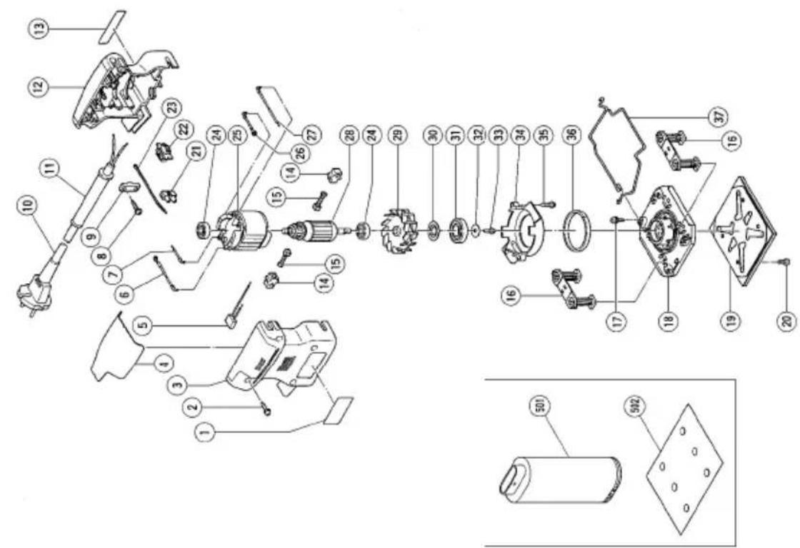
Line drawing of a sewing machine labeled SV8SA, showing mechanical components and base plate (no text or symbols on the device itself)Parts are subject to possible modification without notice due to improvements.
The drawing and the list are parts structural drawing and parts list of model SV12SF. For model SV8SA refer to the drawing and the list.
1
2
3
natural_image
Illustration of hands using a tool to adjust or install a mechanical component (no text or symbols visible)4
5
natural_image
Line drawing of a hand using a power tool on a metal surface (no text or symbols)6
7
natural_image
Line drawing of hands using a tool to adjust or install a mechanical component (no text or symbols present)| Svenska Dansk Norsk | |||
| 1 | Sandpapper Sandpapir Sand papir | ||
| 2 | Dammutblåsningsöppning Støvport Støvventil | ||
| 3 | Dammpåse Støvpose Støvpose | ||
| 4 | Fäste för dammpåse Støvport Støvavløp | ||
| 5 | Dammsugar Støvsuger Støvsamler | ||
| 6 | Adapter Adapter Adapter | ||
| 7 | Slang Slange Slange | ||
| 8 | Hålslangningsplatta Standseplade | Slagplate |
○80 x 130 mm svamppute (borrelåstype)
○110 x 100 mm svamppute (borrelåstype)
○110 x 100 mm klebepute
○Ytre diameter 125 mm klebepute
3. Støvsamler (Modell WDE-1200)
4. Slagplate
VEDLIKEHOLD OG INSPEKSJON
- Keep work area clean. Cluttered areas and benches invite injuries.
- Consider work area environment. Don't expose power tools to rain. Don't use power tools in damp or wet locations. Keep work area well lit. Don't use tool in presence of flammable liquids or gases.
Power tools produce sparks during operation. They also spark when switching ON/OFF. Never use power tools in dangerous sites containing lacquer, paint, benzine, thinner, gasoline, gases, adhesive agents, and other materials which are combustible or explosive. - Guard against electric shock. Prevent body contact with grounded surfaces. For example; pipes, radiators, ranges, refrigerator enclosures.
- Keep children away. Do not let visitors contact tool or extension cord. All visitors should be kept away from work area.
- Store idle tools. When not in use, tools should be stored in dry and high or locked-up place out of reach of children.
- Don't force tool. It will do the job better and safer at the rate for which it was intended.
- Use right tool. Don't force small tool or attachment to do the job of a heavy-duty tool. Don't use tool for purpose not intended-for example-don't use circular saw for cutting tree limbs or logs.
- Dress properly. Do not wear loose clothing or jewelry. They can be caught in moving parts. Rubber gloves and non-skid footwear are recommended when working outdoors. Wear protective hair covering to contain long hair.
- Use safety glasses. Also use face or dust mask if cutting operation is dusty.
- Don't abuse cord. Never carry tool by cord or yank it to disconnect from receptacle. Keep cord from heat, oil and sharp edges.
- Secure work. Use clamps or a vise to hold work. It's safer than using your hand and it frees both hands to operate tool.
- Don't overreach. Keep proper footing and balance at all times.
- Maintain tools with care. Keep tools sharp and clean for better and safer performance. Follow instructions for lubricating and changing accessories. Inspect tool cords periodically and if damaged, have repaired by authorized service center. Inspect extension cords periodically and replace if damaged. Keep handles dry, clean, and free from oil and grease.
- Disconnect tools. When not in use, before servicing, and when changing accessories, such as blades, bits, cutters.
- Remove adjusting keys and wrenches. Form habit of checking to see that keys and adjusting wrenches are removed from tool before turning it on.
- Avoid unintentional starting. Don't carry plugged in tool with finger on switch. Be sure switch is off when plugging in.
- Outdoor use extension cords. When tool is used outdoors, use only extension cords intended for use outdoors and so marked.
-
Stay alert. Watch what you are doing. Use common sense. Do not operate tool when you are tired.
-
Check damaged parts. Before further use of the tool, a guard or other part that is damaged should be carefully checked to determine that it will operate properly and perform its intended function. Check for alignment of moving parts, binding of moving parts, breakage of parts, mounting, and any other conditions that may affect its operation. A guard or other part that is damaged should be properly repaired or replaced by an authorized service center unless otherwise indicated else where in this handling instructions manual. Have defective switches replaced by authorized service center. Do not use tool if switch does not turn it on and off.
-
Do not use power tools for applications other than those specified in the Handling Instructions.
-
To ensure the designed operational integrity of power tools, do not remove installed covers or screws.
-
Do not touch movable parts or accessories unless the power source has been disconnected.
-
Use your tool at lower input than specified on the nameplate; otherwise, the finish may be spoiled and working efficiency reduced due to motor overload.
-
Do not wipe plastic parts with solvent. Solvents such as gasoline, thinner, benzine, carbon tetrachloride, alcohol, ammonia and oil containing chloric annex may damage and crack plastic parts. Do not wipe them with such solvent. Wipe plastic parts with a soft cloth lightly dampened with soapy water.
-
Consult an authorized Service Agent in the event of power tool failure.
-
Use only genuine HITACHI replacement parts.
SPECIFICATIONS
| Model SV8SA SV12SF | ||
| Voltage (by areas)* (110V, 115V, 120V, 127V, 220V, 230V, 240V) | ||
| Power Input* 200 W | ||
| No-Load Speed 14000/min. | ||
| Sanding pad size 80 mm x 130 mm | 110 mm x 100 mm | |
| Sanding paper size 80 mm x 170 mm | 114 mm x 140 mm | |
| Weight (without cord) 1.1 kg | ||
* Be sure to check the nameplate on product as it is subject to change by areas.
STANDARD ACCESSORIES
○Sanding paper (Grain: AA100) 1
○Dust bag 1
Standard accessories are subject to change without notice.
OPTIONAL ACCESSORIES (sold separately)
1. Sanding paper
○80 x 170 mm paper clip type sanding paper Grain: AA60, AA100, AA150
○80 x 130 mm Velcro type sanding paper Grain: AA60, AA100, AA150
○114 x 140 mm paper clip type sanding paper Grain: AA60, AA100, AA150
○110 x 100 mm Velcro type sanding paper Grain: AA60, AA100, AA150
○110 x 100 mm stick-on type sanding paper Grain: AA60, AA80, AA100, AA120, AA150, AA180
○Outer diameter 125 mm stick-on type sanding paper Grain: AA60
2. Sanding pad
○80 x 130 mm sponge pad (Velcro type)
○110 x 100 mm sponge pad (Velcro type)
○110 x 100 mm stick-on pad
○Outer diameter 125 mm stick-on pad
3. Dust collector (Model WDE-1200)
4. Punch plate
Optional accessories are subject to change without notice.
APPLICATIONS
○Finish polishing of woodwork surfaces
○Sanding surfaces of woodwork or sheet metal prior to painting, etc.
PRIOR TO OPERATION
1. Power source
Ensure that the power source to be utilized conforms to the power requirements specified on the product nameplate.
2. Power switch
Ensure that the power switch is in the OFF position. If the plug is connected to a power receptacle while the power switch is in the ON position, the power tool will start operating immediately, which could cause a serious accident.
3. Extension cord
When the work area is removed from the power source, use an extension cord of sufficient thickness and rated capacity. The extension cord should be kept as short as practicable.
4. Installing the sanding paper
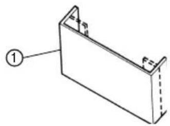
(1) Bending the sanding paper:
Position the sander with its pad side facing upward as shown in Fig. 1. Place the sanding paper on the pad so that the center of the sanding paper is aligned with the center of the pad, and bend both ends of the sanding paper at a 90° angle. Then, bend both ends again in the manner shown in Fig. 2. The sanding paper is now ready to be installed on the sander.
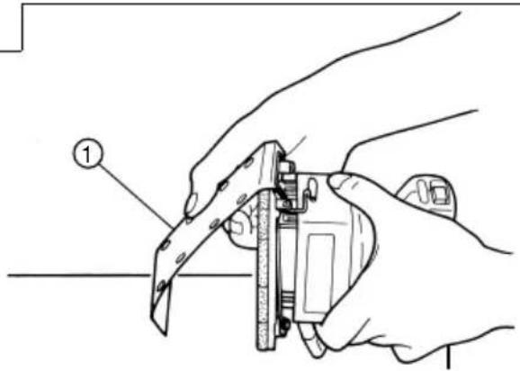
(2) Installing the sanding paper:
While ensuring that the cord is not bent, place the sander on a workbench as shown in Fig. 3, and insert one end of the sanding paper (bent section). Next, insert the remaining bent section in the same manner.
CAUTION
The sanding paper must be precisely installed on the pad, ensuring that there is ample tension (leaving no slack). Loosely installed sanding paper could result in unevenly sanded surfaces and/or damage to the sanding paper itself.
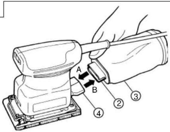
5. Attaching and Removing the Dust Bag
(1) Attaching the Dust Bag
As shown in Fig. 4, hold the dust gate and push it in the direction of Arrow A to attach it to the dust outlet.
(2) Removing the Dust Bag
As shown in Fig 4, hold the dust gate and pull it in the direction of Arrow B to remove it from the dust outlet.
PRACTICAL OPERATING PROCEDURES
CAUTION
Never apply water or grinding fluid when sanding. This could result in electrical shock.
1. Switching the sander ON and OFF
The power can be turned on by setting the lever to ON (1) and turned off by setting the lever to OFF (0).
CAUTION
Never turn the power switch ON when the sander is contacting the surface to be sanded. This is necessary to preclude damage to the material. The same applies when switching the power OFF.
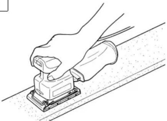
2. How to hold the orbital sander
While gripping the housing, lightly press the sander against the surface to be sanded so that the sanding paper uniformly contacts the surface, as shown in
Fig. 5. DO NOT apply excessive pressure to the sander while sanding. Excessive-pressure may cause overload of the motor, reduced service life of the sanding paper, and lowered sanding or polishing efficiency.
3. How to move the orbital sander
For optimum operating efficiency, alternately move the sander forward and backward at a constant speed and balance.
4. After installing new sanding paper
Movement of the sander may tend to become unsteady after new sanding paper has been installed, because of the new, coarse grain of the paper. This can be avoided by slightly tilting the sander forward or backward during sanding or polishing. Sander movement will become steady as the sanding paper surface becomes properly abraded.
MOUNTING THE OPTIONAL ACCESSORIES
1. Attaching a Sponge Pad (Velcro type) or a Stick-on Pad
Loosen the M4 x 10 screws (4) and remove the attached pad. Next, attach a sponge pad (Velcro type) or a stick-on pad.
CAUTION
Replace the pad only. Use the other parts without removing them.
2. Attaching Velcro Type Sanding Paper or Stick-on Type Sanding Paper
Match the sanding paper's hole with the pad's hole and strongly push the sanding paper with the palm of your hand to fasten it securely in place.
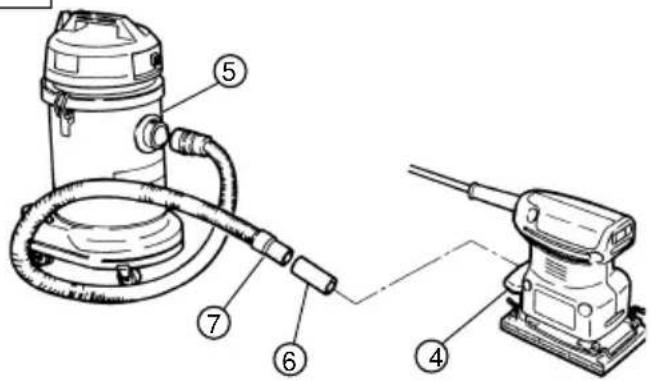
3. When collecting dust with the Dust Collector (Model WDE-1200)
By attaching the Dust Collector (Model WDE-1200), it is possible to carry out clean sanding.
As shown in Fig. 6, attach the adapter, hose and dust collector in order to the dust outlet.
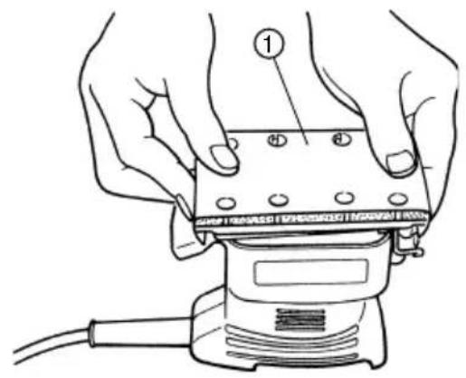
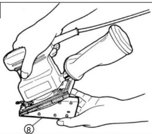
4. Making a Hole in the Sanding Paper with the Punch Plate (Fig. 7)
When using sanding paper without holes in it, punch holes in it with the punch plate to improve dust collecting capacity.
MAINTENANCE AND INSPECTION
1. Emptying and cleaning the Dust Bag
If the dust bag contains too much saw dust, dust collection will be affected. Empty the dust bag when it gets full.
Remove the dust bag, open the fastener, and dispose of the contents.
2. Inspecting the sanding paper
Since use of worn-out sanding paper will degrade efficiency and cause possible damage to the pad, replace the sanding paper as soon a excessive abrasion is noted.
3. Inspecting the mounting screws:
Regularly inspect all mounting screws and ensure that they are properly tightened. Should any of the screws be loose, retighten them immediately. Failure to do so could result in serious hazard.
4. Maintenance of the motor
The motor unit winding is the very “heart” of the power tool.
Exercise due care to ensure the winding does not become damaged and/or wet with oil or water.
5. Servicing
Consult an authorized Service Agent in the event of power tool failure.
NOTE
Due to HITACHI's continuing program of research and development, the specifications herein are subject to change without prior notice.
Information concerning airborne noise and vibration
The measured values were determined according to EN50144.
The typical A-weighted sound pressure level: 85 dB (A).
Wear ear protection.
The typical weighted root mean square acceleration value does not exceed 2.5 m/s^2 .

natural_image
Line drawing of a quill pen in an inkwell (no text or symbols)| Svenska | Suomi | ||
| EF-DEKLARATION BETRÄFFANDE LIKFORMIGHETVi tillkännagiver med eget ansvar att denna produkt överensstämmer med standard eller standardiserat dokument EN50144, HD400, EN55014, EN60555 och/eller EN50082-1 i enlighet med råddirektiven 73/23/E∅S, 89/392/E∅S och/eller 89/336/E∅S.* Denna deklaration gäller för CE-märkningen på produkten. | EY-ILMOITUS YHDENMUKAISUUDESTAYksinomaisellavastuudellavakuutamme, että tämä tuote vastaa normeja tai normitettuja dokumentteja EN50144, HD400, EN55014, EN60555 ja/tai EN50082-1 yhteisön ohjeiden 73/23/ETY, 89/392/ETY ja/tai 89/336/ETY mukaisesti.* Tämä ilmoitus sovelletaan tuotekohtaiseen CE-merkintään. | ||
| Dansk | English | ||
| EF-DEKLARATION OM ENSARTETHEDVi erlkærer os fuldstændige ansvarlige for, at dette produkt modsvarer gældende standard eller de standardiserede dokumenter EN50144, HD400, EN55014, EN60555 og/eller EN50082-1 i overensstemmelse med EF-direktiver 73/23/E∅F 89/392/E∅F og/eller 89/336/E∅F.* Denne erklæring qælder produkter, der er mærket med CE. | EC DECLARATION OF CONFORMITYWe declare under our sole responsibility that this product is in conformity with standards or standardized documents EN50144, HD400, EN55014, EN60555 and/or EN50082-1 in accordance with Council Directives 73/23/EEC, 89/392/EEC and/or 89/336/EEC.* This declaration is applicable to the product affixed CE marking. | ||
| Norsk | |||
| EF's ERKLÆRING OM OVERENSSTEMMELSEVierklærerherved at vi påtar oss eneansvaret for at dette produktet er i overensstermmelse med normer eller standardiserte dokumenter EN 50144, HD400, EN55014, EN60555 og/eller EN50082-1 i samsvar med Rådsdirektiver 73/23/E∅S, 89/392/E∅S og/eller 89/336/E∅S.* Denne erklæringen gjelder produktets påklistrede CE-merking. | |||
| Hitachi Power Tools Europe GmbHSiemensring 34, 47877 Willich, F. R. GermanyHitachi Koki Co., Ltd.Nippon Building, 6-2, Ohtemachi 2-chome,Chiyoda-ku, Tokyo, Japan | CE 95K. Mitsuishi | ||