
DS 9DVC - Drill HITACHI - Free user manual and instructions
Find the device manual for free DS 9DVC HITACHI in PDF.


| Product Type | Cordless Driver Drill |
| Model | DS 9DVC |
| Battery Voltage | 9.6 V |
| Battery Type | Ni-Cd, 1.2 Ah, 8 cells (BCC912) |
| No-Load Speed (Low / High) | 0 – 260 min⁻¹ / 0 – 1150 min⁻¹ |
| Drilling Capacity (Wood) | 21 mm (thickness 18 mm) |
| Drilling Capacity (Steel) | 10 mm |
| Drilling Capacity (Aluminum) | 12 mm |
| Screw Driving Capacity (Machine Screw) | 6 mm |
| Screw Driving Capacity (Wood Screw) | 5.8 mm diameter × 45 mm length (pilot hole required) |
| Weight | 1.2 kg |
| Charger Models | UC18YK (7.2–18 V) or UC9SF (9.6 V) |
| Charging Time (at 20°C) | Approx. 50 min (UC18YK) / Approx. 180 min (UC9SF) |
| Sound Power Level (LWA) | 96 dB(A) (KpA=3 dB(A)) |
| Sound Pressure Level (LpA) | 85 dB(A) (KpA=3 dB(A)) |
| Vibration Emission (ah, D) | 7.8 m/s² (K=1.5 m/s²) |
| Applications | Driving/removing screws; drilling wood, metals |
| Standard Accessories | Plus driver bit (No. 2 × 65L), charger, battery, plastic case |
| Maintenance | Clean with soft dry or soapy cloth; inspect mounting screws; store below 40°C |
| Safety Precautions | Read all safety warnings; wear hearing protection; avoid short circuits; charge between 10–40°C |
| Repair and Spare Parts | Contact Hitachi Authorized Service Center; use only genuine replacement parts |
Frequently Asked Questions - DS 9DVC HITACHI
User questions about DS 9DVC HITACHI
0 question about this device. Answer the ones you know or ask your own.
Ask a new question about this device
Download the instructions for your Drill in PDF format for free! Find your manual DS 9DVC - HITACHI and take your electronic device back in hand. On this page are published all the documents necessary for the use of your device. DS 9DVC by HITACHI.
USER MANUAL DS 9DVC HITACHI
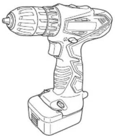
Cordless Driver Drill
DS 9DVC · DS 12DVC
natural_image
Line drawing of a handheld electric drill (no text or symbols)DS12DVC
Read through carefully and understand these instructions before use.
Bruksanvisning
Brugsanvisning
Bruksanvisning
Käyttöohjeet
Handling Instructions




natural_image
Line drawing of a hand holding a small mechanical component (no text or symbols)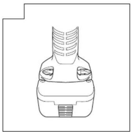
natural_image
Line drawing of a mechanical component with ventilation slots and a base (no text or symbols)| Svenska Dansk | Norsk Suomi English | ||||
| 1 | 9,6 volts uppladdningsbart batteri (gäller DS9DVC) | 9,6 V genopladeligt batteri (til DS9DVC) | 9,6 V oppladbart batteri (for DS9DVC) | 9,6 V ladattava paristo (mallille DS9DVC) | 9.6 V Rechargeable battery (For DS9DVC) |
| 2 | 12 volts uppladdningsbart batteri (gäller DS12DVC) | 12 V genopladeligt batteri (til DS12DVC) | 12 V oppladbart batteri (for DS12DVC) | 12 V ladattava paristo (mallille DS12DVC) | 12 V Rechargeable battery (For DS12DVC) |
| 3 | Lås Smæklås Sperreh | ake Salpa Latch | |||
| 4 | Dra ut Træk ud Dra ut Ota ulos Pull out | ||||
| 5 | Passa in Ilæg Sett i Pa | na sisään Insert | |||
| 6 | Handtag | Håndtag | Håndtak Kahva | Handle | |
| 7 | Tryck | Tryk | Skyv | Työnnä | Push |
| 8 | Passa in Ilæg Sett i Pa | na sisään Insert | |||
| 9 | Signallampa | Kontrollampe | Pilot-lys | Markkivalo | Pilot lamp |
| 10 | Hål för iläggning av det uppladdnings- bara batteriet | Hul til tilslutning af det opladelige batteri | Hull for tilkopling av det oppladbare batteriet | Ladattavan pariston liitäntäaukko | Hole for connecting the rechargeable battery |
| 11 | Borrläge | Boremærkning | Bormerke | Porausmerkki | Drill mark |
| 12 | Momentinställning | Koblingsskive | Justeringsring | Kytkimen valitsin | Clutch dial |
| 13 | Triangelmärke | Trekantmærke | Trekantmerke | Kolmikulmiomerkki | Triangle mark |
| 14 | Svag åtdragningskraft | Svag | Svak Kevyt Weak | ||
| 15 | Stark åtdragningskraft | Stærk | Sterk | Vahva Strong | |
| 16 | Linje | Linie | Linje | Viiva | Line |
| 17 | Hastighetsomkopplare | Omskifterknap | Omskifterbryter | Liukunäppäin | Shift knob |
| 18 | Låg hastighet | Lav hastighed | Lav hastighet | Hidas | Low speed |
| 19 | Hög hastighet | Høj hastighed | Høy hastighet | Nopea | High speed |
| 20 | Ring | Ring | Ring | Rengas | Ring |
| 21 | Chuckhylsa | Muffe | Muffe | Holkki | Sleeve |
| 22 | Dra åt | Fastgøre | Stramme | Kirstää | Tighten |
| 23 | Lossa | Løsne Løsne Irrottaa | Loosen | ||
| 24 | Startomkopplare | Aftrækkerkontakt | Starbryter | Käynnistysliipaisin | Trigger switch |
| 25 | Väljarknapp | Vælgerknap | Velgerknapp | Valintapainike | Selector button |
| 26 | Lägena (R) (höger) och (L) (väster) | (R) og (L) afmærkning | (R) og (L) merker | (R) ja (L) merkit | (R) and (L) marks |
| 27 | Batteriinställningslampa | Batterisætlampe | Batterisett-lys | Akku asetettu -merkkivalo | Battery set lamp |
| Symboler⚠️VARNINGNedan visas de symbolersom används för maskinen.Se till att du förstår vad debetyder innan verktygetanvänds. | Symboler⚠️ADVARSELDet følgende visersymboler, som anvendesfor maskinen. Vær sikker på, at du forstårderes betydning, indendu begynder at brugemaskinen. | Symboler⚠️ADVARSELFølgende symboler brukesfor maskinen. Sørg for åforstå betydningen av dissesymbolene før maskinentas i bruk. | |
 | Läs allasäkerhetsvarningar ochalla instruktioner.Underlåtenhet attfölja varningarna ochinstruktionerna nedan kanresultera i elstötar, brandoch/eller allvarliga skador. | Læs allesikkerhedsadvarsler oginstruktioner.Det kan medføre elektriskstød, brand og/elleralvorlig personskade,hvis alle advarslerne oginstruktionerne nedenforikke overholdes. | Les alle advarsler ogsikkerhetsinstruksjoner.Hvis du ikke følger alleadvarsler og instruksjonerkan bruk av utstyretresultere i elektrisk støt,brann og/eller alvorligpersonskade. |
 | Gäller endast EU-länderElektriska verktyg får intekastas i hushållssoporna!Enligt direktivet 2002/96/EG som avser äldreelektrisk och elektroniskutrustning och desstillämpning enligt nationelllagstiftning ska uttjäntaelektriska verktyg sorterasseparat och lämnas tillmiljövänlig återvinning. | Kun for EU-landeElværktøj må ikkebortskaff es som almindeligtaff ald!I henhold til det europæiskedirektiv 2002/96/EF ombortskaff else af elektriskeog elektroniske produkterog gældende nationallovgivning skal brugtelværktøj indsamlesseparat og bortskaff espå en måde, der skånermiljøet mest muligt. | Kun for EU-landKast aldri elektroverktøy ihusholdningsavfallet!I henhold til’EU-direktiv2002/96/EF om kasserteelektriske og elektroniskeprodukter og direktivetsiverksetting i nasjonalrett, må elektroverktøysom ikke lenger skalbrukes, samles separat ogreturneres til et miljøvennliggjenvinningsanlegg. |
| Symbolit⚠️VAROITUSSeuraavassa on näytettykoneessa käytetyt symbolit.Varmista, että ymmärrätniiden merkityksen ennenkuin aloitat koneen käytön. | Symbols⚠️WARNINGThe following showsymbols used for themachine. Be sure that youunderstand their meaningbefore use. | ||
 | Lue kaikki turvallisuuttakoskevat varoitukset jakaikki ohjeet.Jos varoituksia ja ohjeitaei noudateta, on olemassasähköiskun, tulipalon ja/taivakavan henkilövahingonvaara. | Read all safety warningsand all instructions.Failure to follow thewarnings and instructionsmay result in electric shock,fi re and/or serious injury. | |
 | Koskee vain EU-maitaÄlä hävitä sähkötyökaluatavallisen kotitalousjätteenmukana!Vanhoja sähkö- jaelektroniikkalaitteitakoskevan EU-direktiivin2002/96/ETY ja senmaakohtaisten sovellustenmukaisesti käytetytsähkötyökalut ontoimitettava ongelmajätteenkeräyspisteeeseenja ohjattavaympäristöystävälliseenkierrätykseen. | Only for EU countriesDo not dispose of electroctools together withhousehold waste material!In observance of EuropeanDirective 2002/96/ECon waste electrical andelectronic equipmentand its implementation inaccordance with nationallaw, electric tools thathave reached the end oftheir life must be collectedseparately and returnedto an environmentallycompatible recyclingfacility. |
ALLMÄNNA SÄKERHETSVARNINGAR FÖR ELEKTRISKA VERKTYG
WARNING
VEDLIKEHOLD OG INSPEKSJON
Read all safety warnings and all instructions.
Failure to follow the warnings and instructions may result in electric shock, fi re and/or serious injury.
Save all warnings and instructions for future reference.
The term “power tool” in the warnings refers to your mains-operated (corded) power tool or battery-operated (cordless) power tool.
1) Work area safety
a) Keep work area clean and well lit.
Cluttered or dark areas invite accidents.
b) Do not operate power tools in explosive atmospheres, such as in the presence of fl ammable liquids, gases or dust.
Power tools create sparks which may ignite the dust or fumes.
c) Keep children and bystanders away while operating a power tool.
Distractions can cause you to lose control.
2) Electrical safety
a) Power tool plugs must match the outlet.
Never modify the plug in any way.
Do not use any adapter plugs with earthed (grounded) power tools.
Unmodifi ed plugs and matching outlets will reduce risk of electric shock.
b) Avoid body contact with earthed or grounded surfaces, such as pipes, radiators, ranges and refrigerators.
There is an increased risk of electric shock if your body is earthed or grounded.
c) Do not expose power tools to rain or wet conditions.
Water entering a power tool will increase the risk of electric shock.
d) Do not abuse the cord. Never use the cord for carrying, pulling or unplugging the power tool.
Keep cord away from heat, oil, sharp edges or moving parts.
Damaged or entangled cords increase the risk of electric shock.
e) When operating a power tool outdoors, use an extension cord suitable for outdoor use.
Use of a cord suitable for outdoor use reduces the risk of electric shock.
f) If operating a power tool in a damp location is unavoidable, use a residual current device (RCD) protected supply.
Use of an RCD reduces the risk of electric shock.
3) Personal safety
a) Stay alert, watch what you are doing and use common sense when operating a power tool. Do not use a power tool while you are tired or under the influence of drugs, alcohol or medication.
A moment of inattention while operating power tools may result in serious personal injury.
b) Use personal protective equipment. Always wear eye protection.
Protective equipment such as dust mask, non-skid safety shoes, hard hat, or hearing protection used for appropriate conditions will reduce personal injuries.
c) Prevent unintentional starting. Ensure the switch is in the off-position before connecting to power source and/or battery pack, picking up or carrying the tool.
Carrying power tools with your fi nger on the switch or energising power tools that have the switch on invites accidents.
d) Remove any adjusting key or wrench before turning the power tool on.
A wrench or a key left attached to a rotating part of the power tool may result in personal injury.
e) Do not overreach. Keep proper footing and balance at all times.
This enables better control of the power tool in unexpected situations.
f) Dress properly. Do not wear loose clothing or jewellery. Keep your hair, clothing and gloves away from moving parts.
Loose clothes, jewellery or long hair can be caught in moving parts.
g) If devices are provided for the connection of dust extraction and collection facilities, ensure these are connected and properly used.
Use of dust collection can reduce dust related hazards.
4) Power tool use and care
a) Do not force the power tool. Use the correct power tool for your application.
The correct power tool will do the job better and safer at the rate for which it was designed.
b) Do not use the power tool if the switch does not turn it on and off.
Any power tool that cannot be controlled with the switch is dangerous and must be repaired.
c) Disconnect the plug from the power source and/or the battery pack from the power tool before making any adjustments, changing accessories, or storing power tools.
Such preventive safety measures reduce the risk of starting the power tool accidentally.
d) Store idle power tools out of the reach of children and do not allow persons unfamiliar with the power tool or these instructions to operate the power tool.
Power tools are dangerous in the hands of untrained users.
e) Maintain power tools. Check for misalignment or binding of moving parts, breakage of parts and any other condition that may affect the power tools' operation.
If damaged, have the power tool repaired before use.
Many accidents are caused by poorly maintained power tools.
f) Keep cutting tools sharp and clean.
Properly maintained cutting tools with sharp cutting edges are less likely to bind and are easier to control.
g) Use the power tool, accessories and tool bits etc. in accordance with these instructions, taking into account the working conditions and the work to be performed.
Use of the power tool for operations different from those intended could result in a hazardous situation.
5) Battery tool use and care
a) Recharge only with the charger specified by the manufacturer.
A charger that is suitable for one type of battery pack may create a risk of fire when used with another battery pack.
b) Use power tools only with specifically designated battery packs.
Use of any other battery packs may create a risk of injury and fire.
c) When battery pack is not in use, keep it away from other metal objects like paper clips, coins, keys, nails, screws, or other small metal objects that can make a connection from one terminal to another.
Shorting the battery terminals together may cause burns or a fire.
d) Under abusive conditions, liquid may be ejected from the battery; avoid contact. If contact accidentally occurs, fl ush with water. If liquid contacts eyes, additionally seek medical help.
Liquid ejected from the battery may cause irritation or burns.
6) Service
a) Have your power tool serviced by a qualified repair person using only identical replacement parts.
This will ensure that the safety of the power tool is maintained.
PRECAUTION
Keep children and infi rm persons away.
When not in use, tools should be stored out of reach of children and infi rm persons.
PRECAUTIONS FOR CORDLESS DRIVER DRILL
- Always charge the battery at a temperature of 10^ C – 40^ C. A temperature of less than 10^ C will result in over charging which is dangerous. The battery cannot be charged at a temperature higher than 40^ C.
The most suitable temperature for charging is that of 20^ C – 25^ C.
- When one charging is completed, leave the charger for about 15 minutes before the next charging of battery.
Do not charge more than two batteries consecutively.
-
Do not allow foreign matter to enter the hole for connecting the rechargeable battery.
-
Never disassemble the rechargeable battery and charger.
-
Never short-circuit the rechargeable battery. Short-circuiting the battery will cause a great electric current and overheat. It results in burn or damage to the battery.
-
Do not dispose of the battery in fire. If the battery is burnt, it may explode.
-
When drilling in wall, floor or ceiling, check for buried electric power cord, etc.
-
Bring the battery to the shop from which it was purchased as soon as the post-charging battery life becomes too short for practical use. Do not dispose of the exhausted battery.
-
Using an exhausted battery will damage the charger.
-
Do not insert object into the air ventilation slots of the charger.
Inserting metal objects or inflammables into the charger air ventilation slots will result in electrical shock hazard or damaged charger.
-
Do not move the charger by pulling it by the cord. Doing so may lead to damage.
-
When mounting a bit into the keyless chuck, tighten the sleeve adequately. If the sleeve is not tight, the bit may slip or fall out, causing injury.
SPECIFICATIONS
POWER TOOL
| Model | DS9DVC | DS12DVC | ||
| No-load speed (Low/High) | 0 – 260 / 0 – 1150 min ^-1 | 0 – 350 / 0 – 1400 min ^-1 | ||
| Capacity | Drilling | Wood(Thickness 18 mm) | 21 mm | 24 mm |
| Metal(Thickness 1.6 mm) | Steel: 10 mmAluminum: 12 mm | Steel: 12 mmAluminum: 15 mm | ||
| Driving | Machine screw | 6 mm | 6 mm | |
| Wood screw | 5.8 mm (diameter) × 45 mm (length)(Requires a pilot hole) | 5.8 mm (diameter) × 45 mm (length)(Requires a pilot hole) | ||
| Rechargeable battery | BCC912: Ni-Cd 9.6 V (1.2 Ah 8 cells) | BCC1212: Ni-Cd 12 V (1.2 Ah 10 cells) | ||
| Weight | 1.2 kg | 1.3 kg | ||
CHARGER
| Model | UC18YK | UC9SF | UC12SF |
| Charging voltage | 7.2 – 18 V | 9.6 V | 12 V |
| Weight | 0.35 kg | 0.6 kg | 0.6 kg |
STANDARD ACCESSORIES
In addition to the main unit (1), the package contains the accessories listed in the table below.
| DS9DVC DS12DVC | 1 Plus driver bit (No. 2 × 65L) .....1 |
| 2 Charger (UC18YK or UC9SF or UC12SF) .....1 | |
| 3 Battery.....2 or Battery.....1 | |
| 4 Plastic case .....1 |
Standard accessories are subject to change without notice.
OPTIONAL ACCESSORIES (sold separately)
- Battery (BCC912)
(For DS9DVC)
- Battery (BCC1212)
(For DS12DVC)
Optional accessories are subject to change without notice.
APPLICATIONS
○ Driving and removing of machine screws, wood screws, tapping screws, etc.
○ Drilling of various metals.
○ Drilling of various woods.
BATTERY REMOVAL/INSTALLATION
1. Battery removal
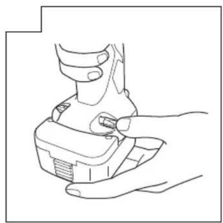
Hold the handle tightly and push the battery latch (2 pcs.) to remove the battery (see Figs. 1 and 2).
CAUTION
Never short-circuit the battery.
2. Battery installation
Insert the battery while observing its polarities (see Fig. 2).
CHARGING
Before using the driver drill, charge the battery as follows.
- Connect the charger power cord to the receptacle Connecting the power cord will turn on the charger.
2. Insert the battery into the charger
Insert the battery firmly while observing its direction, until it contacts the bottom of the charger (See Fig. 3, 4). (The pilot lamp on the UC18YK or the battery set lamp on the UC9SF or UC12SF lights up.)
CAUTION
If the pilot lamp on the UC18YK or the battery set lamp on the UC9SF or UC12SF does not light up when the battery is inserted, pull out the power cord from the receptacle and check the battery mounting condition.
(1) Regarding the temperatures of the rechargeable battery The temperatures for rechargeable batteries are as shown in Table 1.
Table 1 Recharging ranges of batteries
| Rechargeable batteries | Temperatures at which the battery can be recharged |
| BCC912, BCC1212 0°C – 45°C |
(2) Regarding recharging time
Depending on the combination of the charger and batteries, the charging time will become as shown in Table 2.
Table 2 Charging time (At 20°C)
| Battery\Charger | UC18YK | UC12SF | UC9SF |
| BCC1212 | Approx. 50 min. | Approx. 180 min. (Less than 0°C: Approx. 4 to 6 hours) | —— |
| BCC912 | Approx. 50 min. | —— | Approx. 180 min. (Less than 0°C: Approx. 4 to 6 hours) |
UC18YK:
The pilot lamp goes off to indicate that the battery is fully charged.
The battery charging time becomes longer when a temperature is low or the voltage of the power source is too low.
UC9SF or UC12SF:
Using the above times as a guide, remove the battery from the charger.
The battery set lamp goes off when the battery is removed from the charger.
When the temperature of the battery is low (less than 0^ C) or the voltage of the power source is low, the capacity of the battery after charging for 180 minutes is reduced. If the battery performance seems poor during practical use, charge for 4 to 6 hours.
CAUTION
If the battery is heated due to direct sunlight, etc., just after operation, the charger pilot lamp may not light up. At that time, cool the battery first, then start charging.
3. Disconnect the charger's power cord from the receptacle
4. Hold the charger firmly and pull out the battery NOTE
After charging, pull out batteries from the charger first, and then keep the batteries properly.
Regarding electric discharge in case of new batteries, etc.
As the internal chemical substance of new batteries and batteries that have not been used for an extended period is not activated, the electric discharge might be low when using them the first and second time. This is a temporary phenomenon, and normal time required for recharging will be restored by recharging the batteries 2 – 3 times.
How to make the batteries perform longer.
(1) Recharge the batteries before they become completely exhausted.
When you feel that the power of the tool becomes weaker, stop using the tool and recharge its battery. If you continue to use the tool and exhaust the electric current, the battery may be damaged and its life will become shorter.
(2) Avoid recharging at high temperatures.
A rechargeable battery will be hot immediately after use. If such a battery is recharged immediately after use, its internal chemical substance will deteriorate, and the battery life will be shortened. Leave the battery and recharge it after it has cooled for a while.
PRIOR TO OPERATION
1. Setting up and checking the work environment
Check if the work environment is suitable by following the precautions.
HOW TO USE
1. Confi rm the clutch dial position (See Fig. 5)
The tightening torque of this unit can be adjusted according to the clutch dial position, at which the clutch dial is set.
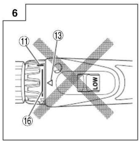
(1) When using this unit as a screwdriver, line up the one of the numbers “1, 5, 9 ... 21” on the clutch dial, or the dots, with the triangle mark on the outer body.
(2) When using this unit as a drill, align the clutch dial drill mark "###" with the triangle mark on the outer body.
CAUTION
○ The clutch dial cannot be set between the numerals “1, 5, 9 ... 21” or the dots.
Do not use with the clutch dial numeral between "21" and the line at the middle of the drill mark. Doing so may cause damage (See Fig. 6).
2. Tightening torque adjustment
(1) Tightening torque
Tightening torque should correspond in its intensity to the screw diameter. When too strong torque is used, the screw head may be broken or be injured. Be sure to adjust the clutch dial position according to the screw diameter.
(2) Tightening torque indication
The tightening torque differs depending on the type of screw and the material being tightened.
The unit indicates the tightening torque with the numbers "1, 5, 9 ... 21" on the clutch dial, and a dots. The tightening torque at position "1" is the weakest and the torque is strongest at the highest number (See Fig. 5).
(3) Adjusting the tightening torque
Rotate the clutch dial and line up the numbers “1, 5, 9 ... 21” on the clutch dial, or the dots, with the triangle mark on the outer body. Adjust the clutch dial in the weak or the strong torque direction according to the torque you need.
CAUTION
☐ The motor rotation may be locked to cease while the unit is used as drill. While operating the driver drill, take care not to lock the motor.
☐ Too long hammering may cause the screw broken due to excessive tightening.
3. Change rotation speed
Operate the shift knob to change the rotational speed. Move the shift knob in the direction of the arrow (See Figs. 7 and 8).
When the shift knob is set to "LOW", the drill rotates at a low speed. When set to "HIGH", the drill rotates at a high speed.
CAUTION
○ When changing the rotational speed with the shift knob, confirm that the switch is off.
Changing the speed while the motor is rotating will damage the gears.
When setting the shift knob to "HIGH" (high speed) and the position of the clutch dial is "17" or "21", it may happen that the clutch does not engage and that the motor is locked. In such a case, please set the shift knob to "LOW" (low speed).
☐ If the motor is locked, immediately turn the power off. If the motor is locked for a while, the motor or battery may be burnt.
4. The scope and suggestions for uses
The usable scope for various types of work based on the mechanical structure of this unit is shown in Table 3.
Table 3
| Work Suggestions | ||
| Drilling | Wood | Use for drilling purpose. |
| Steel | ||
| Driving | Machine screw Use the bit or socket matching the screw diameter. | |
| Wood screw | Use after drilling a pilot hole. | |
5. How to select tightening torque and rotational speed
Table 4
| Use | Clutch Dial Position | Rotating speed selection (Position of the shift knob) | ||
| LOW (Low speed) HIGH (High speed) | ||||
| Driving | Machine screw 1 | -21 | For 6 mm or smaller diameter screws. | For 6 mm or smaller diameter screws. |
| Wood screw |  | For 5.8 mm or smaller nominal diameter screws. | For 3.8 mm or smaller nominal diameter screws. | |
| Drilling | Wood | For 25 mm or smaller diameters. (DS12DVC) | For 12 mm or smaller diameters. | |
| For 21 mm or smaller diameters. (DS9DVC) | ||||
| Metal | For drilling with a metal working drill bit. | ____ | ||
CAUTION
☐ The selection examples shown in Table 4 should be considered as general standard. As different types of tightening screws and different materials to be tightened are used in actual works proper adjustments are naturally necessary.
When using the driver drill with a machine screw at HIGH (high speed), a screw may damage or a bit may lose due to the tightening torque is too strong. Use the driver drill at LOW (low speed) when using a machine screw.
6. Mounting and dismounting of the bit
(1) After inserting a driver bit, etc. into the keyless drill chuck, firmly grasp the ring and tighten the sleeve by turning it toward the right (in the clockwise direction as viewed from the front) (See Fig. 9).
○ If the sleeve becomes loose during operation, tighten it further. The tightening force becomes stronger when the sleeve is tightened additionally.
(2) Dismounting the bit
Firmly grasp the ring and loosen the sleeve by turning it toward the left (in the counter-clockwise direction as viewed from the front) (See Fig. 9).
7. Confir rm that the battery is mounted correctly
8. Check the rotational direction
The bit rotates clockwise (viewed from the rear side) by pushing the R-side of the selector button.
The L-side of the selector button is pushed to turn the bit counterclockwise (See Fig. 10) (The (L) and (R) marks are provided on the body).
9. Switch operation
○ When the trigger switch is depressed, the tool rotates. When the trigger is released, the tool stops.
☐ The rotational speed of the drill can be controlled by varying the amount that the trigger switch is pulled. Speed is low when the trigger switch is pulled slightly and increases as the trigger switch is pulled more.
NOTE
○ A buzzing noise is produced when the motor is about to rotate; This is only a noise, not a machine failure.
10. Using the bit holder
CAUTION
○ Stow the bit in the specified location on the tool. If the tool is used with the bit stowed improperly, the bit may fall and cause bodily injury.
☐ Do not stow bits that are of a different length, gauge or dimension than the plus driver bit (65 mm long) included in the STANDARD ACCESSORIES.
The bit may fall and cause bodily injury.
(1) Removing the bit
Securely hold the main unit and pull out the bit by holding the tip with your thumb (Fig. 11).
(2) Installing the Bit
Install the bit with steps opposite of when removing. Insert the bit so that the right and left sides are equal, as shown in Fig. 12
MAINTENANCE AND INSPECTION
1. Inspecting the tool
Since use of as dull tool will degrade efficiency and cause possible motor malfunction, sharpen or replace the tool as soon as abrasion is noted.
2. Inspecting the mounting screws
Regularly inspect all mounting screws and ensure that they are properly tightened. Should any of the screws be loose, retighten them immediately. Failure to do so could result in serious hazard.
3. Cleaning on the outside
When the driver drill is stained, wipe with a soft dry cloth or a cloth moistened with soapy water. Do not use chloric solvents, gasoline or paint thinner, for they melt plastics.
4. Storage
Store the driver drill in a place in which the temperature is less than 40^ C and out of reach of children.
5. Service parts list
CAUTION
Repair, modification and inspection of Hitachi Power Tools must be carried out by a Hitachi Authorized Service Center.
This Parts List will be helpful if presented with the tool to the Hitachi Authorized Service Center when requesting repair or other maintenance.
In the operation and maintenance of power tools, the safety regulations and standards prescribed in each country must be observed.
MODIFICATIONS
Hitachi Power Tools are constantly being improved and modified to incorporate the latest technological advancements.
Accordingly, some parts may be changed without prior notice.
Important notice on the batteries for the Hitachi cordless power tools
Please always use one of our designated genuine batteries. We cannot guarantee the safety and performance of our cordless power tool when used with batteries other than these designated by us, or when the battery is disassembled and modified (such as disassembly and replacement of cells or other internal parts).
GUARANTEE
We guarantee Hitachi Power Tools in accordance with statutory/country specific regulation. This guarantee does not cover defects or damage due to misuse, abuse, or normal wear and tear. In case of complaint, please send the Power Tool, undismantled, with the GUARANTEE CERTIFICATE found at the end of this Handling instruction, to a Hitachi Authorized Service Center.
NOTE
Due to HITACHI's continuing program of research and development, the specifications herein are subject to change without prior notice.
Information concerning airborne noise and vibration
The measured values were determined according to EN60745 and declared in accordance with ISO 4871.
Measured A-weighted sound power level: 96 dB (A)
Measured A-weighted sound pressure level: 85 dB (A)
Uncertainty KpA: 3 dB (A).
Wear hearing protection.
Vibration total values (triax vector sum) determined according to EN60745.
Vibration emission value ah,D=7.8~m/s^2
Uncertainty K = 1.5 m/s²
The declared vibration total value has been measured in accordance with a standard test method and may be used for comparing one tool with another.
It may also be used in a preliminary assessment of exposure.
WARNING
☐ The vibration emission during actual use of the power tool can differ from the declared total value depending on the ways in which the tool is used.
○ Identify safety measures to protect the operator that are based on an estimation of exposure in the actual conditions of use (taking account of all parts of the operating cycle such as the times when the tool is switched off and when it is running idle in addition to the trigger time).
| ITEM NO. | PART NAME Q'TY | |
| 37 | NAME PLATE | 1 |
| 38 | TAPPING SCREW (W/FLANGE) D3× 16 | 8 |
| 39-1 | BATTERY (BCC912) | 2 |
| 39-2 | BATTERY (BCC1212) | 1 |
| 501 | PLUS DRIVER BIT (C) | 1 |
| 502-1 | CHARGER (UC18YK) | 1 |
| 502-2 | CHARGER (UC9SF, UC12SF) | 1 |
| 503 | CASE | 1 |
| ITEM NO. | PART NAME Q'TY | |
| 1 | SPECIAL SCREW(LEFT HAND) (B) M5 x 25 | 1 |
| 2 | KEYLESS CHUCK 1 | |
| 3 | GEAR BOX ASS'Y 1 | |
| 4 | CLUTCH DIAL 1 | |
| 5 | CLICK SPRING 1 | |
| 6 | NUT 1 | |
| 7 | SPRING 1 | |
| 8 | THRUST PLATE 1 | |
| 9 | GEAR CASE 1 | |
| 10 | STEEL BALL D5 6 | |
| 11 | SHIFT ARM 1 | |
| 12 | RING GEAR 1 | |
| 13 | CARRIER 1 | |
| 14 | WASHER (B) 1 | |
| 15 | PINION (C) | 1 |
| 16 | NEEDLE | 2 |
| 17 | TAPPING SCREW D2 x3.5 | 2 |
| 18 | PLANET GEAR (C) | 3 |
| 19 | PLANET GEAR (B) | 3 |
| 20 | SLIDE RING GEAR | 1 |
| 21 | WASHER (C) 1 | |
| 22 | PINION (B) | 1 |
| 23 | PLANET GEAR (A) | 3 |
| 24 | FIRST RING GEAR | 1 |
| 25 | WASHER (A) 1 | |
| 26 | MOTOR SPACER | 1 |
| 27 | MOTOR | 1 |
| 28 | LEAD WIRE (B) | 1 |
| 29 | MACHINE SCREW(W/SP. WASHER) M3 x8 | 2 |
| 30 | LEAD WIRE (B) 90L | 1 |
| 31 | HITACHI LABEL 1 | |
| 32 | HOUSING (A) (B) SET | 1 |
| 33 | PUSHING BUTTON | 1 |
| 34 | SWITCH TERMINAL | 1 |
| 35 | TERMINAL SUPPORT (A) | 1 |
| 36 | SHIFT KNOB | 1 |

Hitachi Power Tools Norway AS
Kjeller Vest 7
Postboks 124, 2007 Kjeller, Norway
Tel: (+47) 6692 6600
Fax: (+47) 6692 6650
URL: http://www.markt.no
Hitachi Power Tools Sweden AB
Rotebergsvagen 2B
SE-192 78 Sollentuna, Sweden
Tel: (+46) 8 598 999 00
Fax: (+46) 8 598 999 40
URL: http://www.markt.se
Hitachi Power Tools Denmark AS
Lillebaeltsvej 90
DK-6715 Esbjerg N, Denmark
Tel: (+45) 75 14 32 00
Fax: (+45) 75 14 36 66
URL: http://www.markt.dk
Hitachi Power Tools Finland OY
Tupalankatu 9
FIN-15680 Lahti, Finland
Tel: (+358) 20 7431 530
Fax: (+358) 20 7431 531
URL: http://www.markt.fi
| Svenska Suomi | |||
| EF-DEKLARATION BETRÄFFANDE LIKFORMIGHETVi tillkännagiver med eget ansvar att denna produkt överensstämmer med standard eller standardiserings dokument EN60745, EN60335, EN55014 och EN61000 i enlighet med direktiven 2004/108/EF, 2006/95/EF och 2006/42/EF.Den europeiska standardansvarige på Hitachi Koki Europe Ltd. är auktoriserad att utarbeta den tekniska filen.Denna deklaration gäller för CE-märkningen på produkten. | EY-ILMOITUS YHDENMUKAISUUDESTAYksinomaisella vastuudella vakuutamme, että tämä tuote vastaa tai normitettuja dokumentteja EN60745, EN60335, EN55014 ja EN61000 ohjeiden 2004/108/EY, 2006/95/EY ja 2006/42/EY mukaisesti.Hitachi Koki Europe Ltd.:n eurooppalaisten standardien johtaja on valtuutettu laatimaan tekniset asiakirjat.Tämä ilmoitus sovelletaan tuotekohtaiseen CE-merkintään. | ||
| Dansk English | |||
| EF-OVERENSS TEMMELSESERKLÆRINGVi erlkærer os fuldstændige ansvarlige for, at dette produkt modsvarer gældende standard eller standardiserings dokumenter EN60745, EN60335, EN55014 og EN61000 i overensstemmelse med direktiver 2004/108/EF, 2006/95/EF og 2006/42/EF.Chefen for europæiske standarder hos Hitachi Koki Europe Ltd. er autoriseret til at kompilere den tekniske fil.Denne erklæring qælder produkter, der er mærket med CE. | EC DECLARATION OF CONFORMITYWe declare under our sole responsibility that this product is in conformity with standards or standardization documents EN60745, EN60335, EN55014 and EN61000 in accordance with Directives 2004/108/EC, 2006/95/EC and 2006/42/EC.The European Standards Manager at Hitachi Koki Europe Ltd. is authorized to compile the technical fi le.This declaration is applicable to the product affixed CE marking. | ||
| Norsk | EF'S ERKLÆRING OM OVERENSSTEMMELSEVi erklærer herved at vi påtar oss det fulle ansvar for at dette produktet er i overensstemmelse med normer eller standardiseringsdokumentene EN60745, EN60335, EN55014 og EN61000 i samsvar med direktivene 2004/108/EF, 2006/95/EF og 2006/42/EF.Lederen for europeiske standarder ved Hitachi Koki Europe Ltd. har fullmakt til å utarbeide det tekniske dokumentet.Denne erklæringen gjelder produktets påklistrede CE-merking. | ||
| Representative offi ce in EuropeHitachi Power Tools Europe GmbHSiemensring 34, 47877 Willich 1, F. R. GermanyTechnical fi le at:Hitachi Koki Europe Ltd.Clonshaugh Business & Technology Park, Dublin 17, IrelandHead offi ce in JapanHitachi Koki Co., Ltd.Shinagawa Intercity Tower A, 15-1, Konan 2-chome, Minato-ku, Tokyo, Japan | |||

Hitachi Koki Co., Ltd.
- Cordless Driver Drill
- DS 9DVC · DS 12DVC
- ALLMÄNNA SÄKERHETSVARNINGAR FÖR ELEKTRISKA VERKTYG
- WARNING
- VEDLIKEHOLD OG INSPEKSJON
- Save all warnings and instructions for future reference.
- 1) Work area safety
- 2) Electrical safety
- 3) Personal safety
- 4) Power tool use and care
- 5) Battery tool use and care
- 6) Service
- PRECAUTION
- PRECAUTIONS FOR CORDLESS DRIVER DRILL
- SPECIFICATIONS
- STANDARD ACCESSORIES
- OPTIONAL ACCESSORIES (sold separately)
- APPLICATIONS
- BATTERY REMOVAL/INSTALLATION
- Battery removal
- CAUTION
- Battery installation
- CHARGING
- Insert the battery into the charger
- Regarding recharging time
- UC18YK:
- UC9SF or UC12SF:
- Disconnect the charger's power cord from the receptacle
- Hold the charger firmly and pull out the battery NOTE
- Regarding electric discharge in case of new batteries, etc.
- How to make the batteries perform longer.
- PRIOR TO OPERATION
- Setting up and checking the work environment
- HOW TO USE
- Confi rm the clutch dial position (See Fig. 5)
- Tightening torque adjustment
- Tightening torque
- Tightening torque indication
- Adjusting the tightening torque
- Change rotation speed
- The scope and suggestions for uses
- How to select tightening torque and rotational speed
- Mounting and dismounting of the bit
- Confir rm that the battery is mounted correctly
- Check the rotational direction
- Switch operation
- NOTE
- Using the bit holder
- MAINTENANCE AND INSPECTION
- Inspecting the tool
- Inspecting the mounting screws
- Cleaning on the outside
- Storage
- Service parts list
- MODIFICATIONS
- Important notice on the batteries for the Hitachi cordless power tools
- GUARANTEE
- Information concerning airborne noise and vibration
- Hitachi Power Tools Norway AS
- Hitachi Power Tools Sweden AB
- Hitachi Power Tools Denmark AS
- Hitachi Power Tools Finland OY
- Hitachi Koki Co., Ltd.
Brand : HITACHI
Model : DS 9DVC
Category : Drill