
BM 60Y - Drill HITACHI - Free user manual and instructions
Find the device manual for free BM 60Y HITACHI in PDF.

| Product Type | Automatic Magnetic Drill Press |
| Brand | Hitachi |
| Model | BM 60Y |
| Voltage (by area) | 110V or 220V ~ |
| Maximum Drilling Capacity (Steel Core Bit) | Diameter: 60 mm, Plate Thickness: 50 mm |
| Power Input (Drill) | 1330 W |
| Power Input (Stand) | 75 W |
| No-Load Speed | 680/540/380/300 min⁻¹ (four speeds) |
| Magnet Dimensions | 100 mm × 196 mm |
| Maximum Stroke | 180 mm |
| Drill Stand Height | 500 mm |
| Weight (without cord) | 25 kg |
| Cord Length | 5 m |
| Feed Modes | Manual and Automatic |
| Electromagnet | Yes, with attracting surface |
| Cutting Solution System | Built-in tank with cock lever adjustment |
| Safety Features | Chain attachment, overload protection, automatic shut-off |
| Standard Accessories | Steel core bit (22 mm), center pin, springs (black & yellow), thrust washer, center pin guide, hexagon bar wrench, 3 wrenches (13,22,27 mm), cutting solution (500 cc) |
| Optional Accessories | Various steel core bits, multi-cutting core bit, chain, spring for thin plate, chuck adapter, adapter set, tapered shank adapter, oil pump, tank kit |
| Maintenance | Adjust sliding part play, inspect carbon brushes, check electromagnet surface, regrind or replace steel core bit |
| Repairability | Service by Hitachi Authorized Service Center; parts list available |
Frequently Asked Questions - BM 60Y HITACHI
User questions about BM 60Y HITACHI
0 question about this device. Answer the ones you know or ask your own.
Ask a new question about this device
Download the instructions for your Drill in PDF format for free! Find your manual BM 60Y - HITACHI and take your electronic device back in hand. On this page are published all the documents necessary for the use of your device. BM 60Y by HITACHI.
USER MANUAL BM 60Y HITACHI
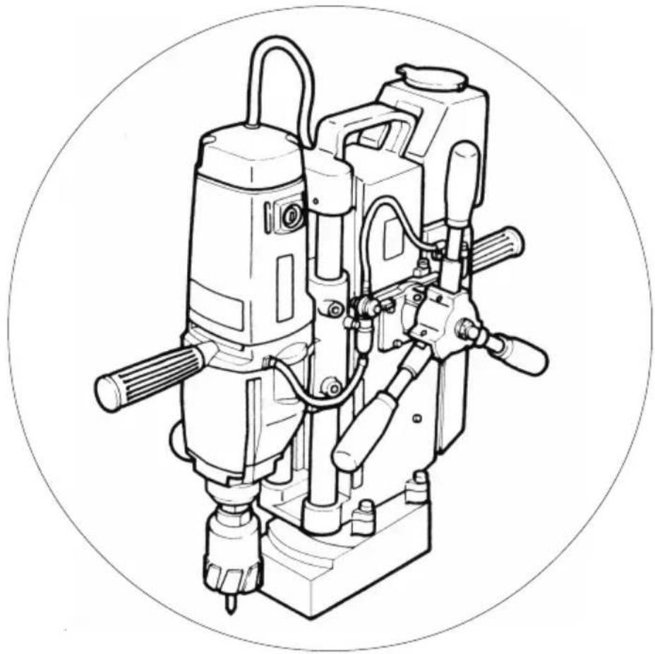
Automatic Magnetic Drill Press
BM 60Y
使用说明书
Handling instructions
natural_image
Technical line drawing of a mechanical drill press assembly (no text or symbols)使用前务请详加阅读
Read through carefully and understand these instructions before use.
一般安全规则
警告!
阅读说明
natural_image
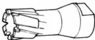
Technical line drawing of a mechanical tool or drill bit (no text or symbols)图1
2. 用于重叠板切削的空心钢钻头
natural_image
Technical line drawing of a mechanical assembly with no visible text or symbolsRead all instructions
Failure to follow all instructions listed below may result in electric shock, fire and/or serious injury.
The term "power tool" in all of the warnings listed below refers to your mains operated (corded) power tool or battery operated (cordless) power tool.
SAVE THESE INSTRUCTIONS
1) Work area
a) Keep work area clean and well lit.
Cluttered and dark areas invite accidents.
b) Do not operate power tools in explosive atmospheres, such as in the presence of flammable liquids, gases or dust.
Power tools create sparks which may ignite the dust of fumes.
c) Keep children and bystanders away while operating a power tool.
Distractions can cause you to lose control.
2) Electrical safety
a) Power tool plugs must match the outlet.
Never modify the plug in any way.
Do not use any adapter plugs with earthed (grounded) power tools.
Unmodified plugs and matching outlets will reduce risk of electric shock.
b) Avoid body contact with earthed or grounded surfaces such as pipes, radiators, ranges and refrigerators.
There is an increased risk of electric shock if your body is earthed or grounded.
c) Do not expose power tools to rain or wet conditions.
Water entering a power tool will increase the risk of electric shock.
d) Do not abuse the cord. Never use the cord for carrying, pulling or unplugging the power tool. Keep cord away from heat, oil, sharp edges or moving parts.
Damaged or entangled cords increase the risk of electric shock.
e) When operating a power tool outdoors, use an extension cord suitable for outdoor use.
Use of a cord suitable for outdoor use reduces the risk of electric shock
3) Personal safety
a) Stay alert, watch what you are doing and use common sense when operating a power tool.
Do not use a power tool while you are tired or under the influence of drugs, alcohol or medication.
A moment of inattention while operating power tools may result in serious personal injury.
b) Use safety equipment. Always wear eye protection.
Safety equipment such as dust mask, non-skid safety shoes, hard hat, or hearing protection used for appropriate conditions will reduce personal injuries.
c) Avoid accidental starting. Ensure the switch is in the off position before plugging in.
Carrying power tools with your finger on the switch or plugging in power tools that have the switch on invites accidents.
d) Remove any adjusting key or wrench before turning the power tool on.
A wrench or a key left attached to a rotating part of the power tool may result in personal injury.
e) Do not overreach. Keep proper footing and balance at all times.
This enables better control of the power tool in unexpected situations.
f) Dress properly. Do not wear loose clothing or jewellery. Keep your hair, clothing and gloves away from moving parts.
Loose clothes, jewellery or long hair can be caught in moving parts.
g) If devices are provided for the connection of dust extraction and collection facilities, ensure these are connected and properly used.
Use of these devices can reduce dust related hazards.
4) Power tool use and care
a) Do not force the power tool. Use the correct power tool for your application.
The correct power tool will do the job better and safer at the rate for which it was designed.
b) Do not use the power tool if the switch does not turn it on and off.
Any power tool that cannot be controlled with the switch is dangerous and must be repaired.
c) Disconnect the plug from the power source before making any adjustments, changing accessories, or storing power tools.
Such preventive safety measures reduce the risk of starting the power tool accidentally.
d) Store idle power tools out of the reach of children and do not allow persons unfamiliar with the power tool or these instructions to operate the power tool.
Power tools are dangerous in the hands of untrained users.
e) Maintain power tools. Check for misalignment or binding of moving parts, breakage of parts and any other condition that may affect the power tools operation.
If damaged, have the power tool repaired before use.
Many accidents are caused by poorly maintained power tools.
f) Keep cutting tools sharp and clean.
Properly maintained cutting tools with sharp cutting edges are less likely to bind and are easier to control.
g) Use the power tool, accessories and tool bits etc., in accordance with these instructions and in the manner intended for the particular type of power tool, taking into account the working conditions and the work to be performed.
Use of the power tool for operations different from intended could result in a hazardous situation.
5) Service
a) Have your power tool serviced by a qualified repair person using only identical replacement parts.
This will ensure that the safety of the power tool is maintained.
PRECAUTION
Keep children and infirm persons away.
When not in use, tools should be stored out of reach of children and infirm persons.
PRECAUTIONS ON USING AUTOMATIC MAGNETIC DRILL PRESS
- Do not use the machine for drilling non-magnetic materials.
As the magnetic drill press drills the workpiece by attracting it with as electromagnet, it is not applicable for drilling non-magnetic materials (aluminum, copper alloy, etc.) which is not attracted by the electromagnet.
- Take special care in handling the electromagnet attracting surface.
If the attracting surface is rusted or has a flaw or dent, it weakens the attracting force of the electromagnet.
Periodically check whether there are any scratches, etc., on the attracting surface.
- Fasten the chain with the body.
This machine is intended for operation on the floor. Do not use it in the ceiling, on a wall or an oblique surface. Always use the chain available as optional accessory while drilling in high places. Fasten the machine to a suitable place in the work area to protect it from falling or moving.
-
Make sure that the electromagnet is not raised. In order to prevent the electromagnet from rising during work, make sure that its whole attracting surface contacts the workpiece and that the body is firmly fastened to the workpiece (for instance by pulling the top of the drill sideways).
-
When opening holes in the thin plate, make sure to use a auxiliary plate.
If the workpiece thickness is too small, the attracting force of the electromagnet is weakened, causing failure of drilling. In such cases, use an auxiliary iron plate to strengthen the attracting force.
- Pay attention to areas below the work site when operating at high places.
When the machine is used at high places, make sure there is nobody below before starting operation.
- Check the mains socket.
If the power cord plug is disconnected from the mains socket during operation, the electromagnet does not work, causing a hazard. Check if the power cord plug is loose and liable to easy disconnection when it is connected to a main socket.
- Do not use this machine with an engine-powered generator or DC power supply.
Connecting this machine to an engine-powered generator can damage the electronic circuits. Do not use it with a DC power supply either. Such usage not only can damage the product, but is also dangerous.
- Do not wear gloves during operation.
Avoid wearing gloves during operation of the machine, because there is a possibility that the gloves may get caught in the machine.
- Wear safety shoes during operation.
As there is a good deal of heavy material handling during operation, wear safety shoes to protect your feet.
- During automatic operation, there must be no obstructions within the movement range.
During automatic operation, there must be no obstructions within the range through which the drill moves up and down or within the range through which the handle rotates.
- Never touch rotating parts.
Keep your hand and body well away from the rotating drill or swarf to avoid injury.
The drill is hot after drilling. Avoid touching it directly when replacing it.
- Eliminate the play of the sliding part.
Play in the sliding parts of the electric drill will shorten the service life of the steel core bit considerably. Adjust the play in the sliding part so the drill does not drop from its own weight when the feed handle is set to manual.
Refer to the section "Maintenance and Inspection" for a description of the adjustment procedures.
- Supply cutting lubricant when using the steel core bit.
Be sure to supply cutting lubricant when using the steel core bit. Otherwise, the blade edge life is greatly reduced.
- When the electromagnet floats away from the work during operation.
Turn the feed handle inversely to eliminate the thrust applied to the drill. If the electromagnet floats away, the attracting force is greatly weakened and it is dangerous to continue operation.
-
Do not stop rotation halfway when manual drilling. If the machine is stopped or locked halfway when manual drilling, the steel core bit blade edge may be damaged. Before stopping the machine, turn the feed handle inversely and withdraw the steel core bit from the material.
-
Pay attention to flying of the cut core (cylindrical cut chip).
Pay attention to flying of the cutting core at the end of drilling with the steel core bit. Particularly, in operation at high places, take care to prevent the falling of the cutting core presenting a hazard. As the cutting core is heated, do not touch it directly with bare hands.
- Be careful of welding machines.
If you work right next to a welding machine, the rotation or feed may be unstable.
- Store the machine in a dry place.
If the machine is stored in a humid place, the electromagnet may become rusted, reducing the attracting force. The electric insulation may also be impaired, presenting the possibility of electric shock.
| Voltage (by areas)* (110V, 220V) | ~ | |
| Maximum drilling capacity | Steel core bit dia.: 60mmMaximum plate thickness: 50mm | |
| Power input | Drill 1330W | |
| Stand | 75W | |
| No-load speed 680/540/380/300/min | ||
| Magnet dimensions 100mm × 196mm | ||
| Maximum stroke 180mm | ||
| Drill stand height 500mm | ||
| Weight (without cord) 25kg | ||
| Cord length 5m | ||
*Be sure to check the nameplate on product as it is subject to change by areas.
STANDARD ACCESSORIES
① Steel core bit (drill dia. 22mm) .....1
② Center pin 1
③ Spring (Black) 1
④ Spring (Yellow, For thin plate) .....1
⑤ Thrust washer ....1
⑥ Center pin guide ....1
⑦ Hexagon bar wrench ....1
⑧ Wrench (13, 22, 27mm) ....3
⑨ Cutting solution (500cc) ....1
Standard accessories are subject to change without notice.
OPTIONAL ACCESSORIES (sold separately)
- Steel core bit (Fig. 1).
| Core bit dia. (mm) | ||||||
| Plate thickness up to 50mm | 18 | 19 | 20 | 21 | 21.5 | 22 |
| 22.5 | 23 | 23.5 | 24 | 24.5 | 25 | |
| 25.5 | 26 | 26.5 | 27 | 28 | 29 | |
| 30 | 31 | 32 | 33 | 34 | 35 | |
| 36 | 38 | 40 | 42 | 45 | 48 | |
| 50 | 52 | 55 | 58 | 60 | ||
natural_image
Technical line drawing of a mechanical component with symmetrical teeth and central bore (no text or symbols)Fig. 1
2. Multi-cutting steel core bit.
Use for drilling through two steel plates at once.
| Core bit diameter (mm) | Plate thickness up to 50 mm | 18 | 22 | 24 | 24.5 |
Observe the following points for usage.
○ Make the gap between the two steel plates no greater than 1mm.
- Firmly secure the two steel plates.
3. Cutting solution.
- Water soluble cutting solution: 1 liter (is a can)
4 liter (is a can)
Thin with one part solution to twenty parts water.
4. Chain.
Use if there is a danger of the machine body dropping.
5. Spring (for use with a plate thickness less than 16mm)
This spring is designed for use on thin plates less than 16mm thick. Use this spring when the cutting core clog easily the holes if the standard accessory thin-plate spring is used.
6. Chuck adapter.
[Using 13mm drill chuck (13VLR)]
Always use the chuck adapter manually.
7. Adapter set (for other companies', cores).
8. Tapered shank adapter.
[Total length 218mm max., #2 Morse taper tapered shank drill installation]
Always use the tapered shank adapter manually.
9. Polyethylene jug (1 liter)
Use this jug to pour the cutting oil into the oil tank.
10. Oil pump (manual).
Capacity 500cc
Vinyl tube (450mm long) accessory
11. Tank kit.
Tank kit for installing large tank
Optional accessories are subject to change without notice.
APPLICATIONS
- Drilling various types of steel plates
Drilling various types of shape steels
This tool should be grounded while in use to protect the operator from electric shock. The tool is equipped with a three-conductor cord and grounding type plug to fit the proper grounding type receptacle. The green (or green and yellow) conductor in the cord is the grounding wire. Never connect the green (or green and yellow) wire to a live terminal.
2. Extension cord.
When the work area is removed from the power source, use an extension cord of sufficient thickness and rated capacity. The extension cord should be kept as short as practicable.
CAUTION:
- Damaged cord must be replaced or repaired.
3. Transporting of the machine.
CAUTION:
When transporting this machine, set the feed handle to automatic (as explained in Item 7 of Usage on Page 19) and fasten so that the electric drill does not move. (Fig. 2)
(1) When moving the machine 1-2m in places with secure foothold, it is convenient to use the grip handle.
(2) When moving the machine a longer distance or moving it at places with insecure foothold, two persons are needed to hold the grip handle and electric drill switch handle. Carry the machine carefully.
NOTE: Do not pull the cord coming from the electric drill.
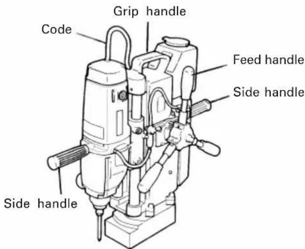
Fig. 2
4. Clean the attracting surface of the electromagnet.
If the attracting surface of the electromagnet is rusted or stained by foreign matter, the attracting force of the electromagnet is weakened. The attracting surface should be kept clean.
5. Keep the chain ready to hand.
If the electromagnet floats away from the attracting surface due to a thrust, the attracting force is greatly weakened and the electromagnet does not work at power failure. Therefore, if there is a possibility of the machine moving or falling during operation at the side of the workpiece or above your head, for example, the machine must be firmly secured to the workpiece beforehand.
Keep the chain (optional accessory) ready at hand to secure the machine in such cases. For how to use the chain, refer to "HOW TO USE, 9". When there is a possibility of the machine body moving.
PRIOR TO USE
1. Power source.
Ensure that the power source to be utilized conforms to the power requirements specified on the product nameplate.
CAUTION:
Connecting this machine to an engine-powered generator can damage the electronic circuits. Do not use it with a DC power supply either. Such usage not only can damage the product, but is also dangerous.
If the voltage of the power supply used is lower than that on the nameplate, the electromagnetic attractive force drops and the electromagnet may float away from the work.
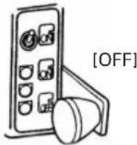
2. Power switch.
Ensure that the power switch is in the [OFF] position. If the plug is connected to a power receptacle while the power switch is in the drill switch [ON] position, the power tool will start operating immediately, inviting serious accident.
3. Attaching the center pin and steel core bit.
This machine has two of the springs marked * in the figure (Fig. 3) (one black and one yellow). Use them as follows according to the plate thickness.
| Spring color | Application |
| Black | Can be used with thin plates and plates up to a maximum thickness of 50mm. |
| Yellow | For thin plates: use this spring when the cutting core jams easily with the black spring. |
CAUTION:
Do not use the yellow spring for drilling plates thicker than 20mm. The spring or the center pin may break.
Use the following procedure to install the center pin and steel core bit.
(1) Pass the center pin through the center pin guide, insert the spring and the thrust washer and install in the threaded section of the spindle. (Fig. 3) After installation, tighten securely with two of the supplied wrenches (13 and 27mm).
NOTE
Do not forget to install the thrust washer. The center pin guide may be difficult to remove.
(2) Install the steel core bit in the center pin guide and tighten securely with two of the supplied wrenches (22 and 27mm).
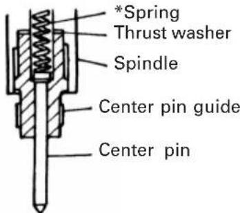
Fig. 3
4. Fill the tank with cutting solution.
Dilute the special cutting solution that is a standard accessory with 20 parts tap water. Remove the tank cap and pour in the cutting solution without spilling it.
CAUTION:
When pouring in the cutting solution, be careful to keep any cutting solution from getting on switch sections or motor sections of this machine.
- The cutting solution can freeze in cold weather.
- Use only the special cutting solution made for this machine.
Do not dilute the cutting solution with well water. Well water can cause rusting in the spindle or allow adhesion of impurities and block the flow of the cutting solution.
5. Check the mains socket.
If the mains socket is too loose or the plug is liable to easy disconnection from the socket, repair is necessary. Consult your nearest electric shop. If the machine is operated without repairing the mains socket, the machine may become overheated, presenting a hazard. If the power cord plug is disconnected during operation, the electromagnet does not work and this is very dangerous.
6. Check that there is no play in sliding sections.
If there is any play in the column and electric drill sliding sections, the lifespan of the steel core bit is drastically reduced. If the electric drill falls freely with the feed handle set to manual, the play has increased, so adjust the play before using. This adjustment is explained in Maintenance and Inspections on Page 22.
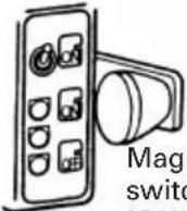
DISPLAY LAMPS
The display lamps change as in the table below according to switch lever operation, the feed handle Manual Feed/Automatic Feed setting, the load, and the power supply voltage.
| Switch lever position | Feed handleAutomatic ↔ ManualFeed Feed | Display lamps Explanation | |
 | <Manual Feed>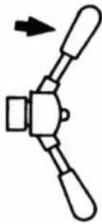 The feed handle can be turned by hand The feed handle can be turned by hand | PowerAutomaticOverload | All the power is cut off for the electromagnet, electric drill, and feed motor. |
Magnet itch N]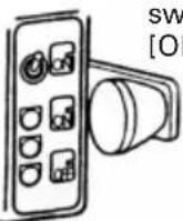 | Power↔ on | The power is on for the electromagnet, so the electromagnet attracts. | |
| The power is on for the electromagnet and the electric drill and the electric drill rotates. | |||
 ch ] ch ]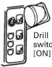 h h | Power↔ onOverload↔ onBlinking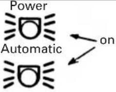  | Overload lamp lit up... Indicates an overload.Overload lamp blinking... An abnormal load has been detected and the electric drill stopped.The power for the electromagnet, elec-tric drill, and feed motor is on.Drilling is carried out automatically. | |
<Automatic Feed>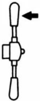 Fastened to the feed handle Fastened to the feed handle | |||
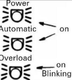 ( ( | Overload lamp lit up... An abnormal load has been detected and the electric drill paused.Overload lamp blinking... An abnormal load has been detected and the feed motor and electric drill stopped. |
CAUTION: (for the 110V model)
 net:h[ON] net:h[ON] | <Manual Feed>or<Automatic Feed> |  Blinking Blinking  | When the power supply voltage is above the usage range, this lamp blinks and the electric drill does not turn.Switch off the power immediately and check the voltage. |
HOW TO USE
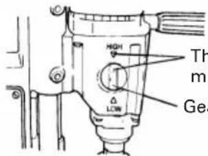
The arrow position must be aligned.
Gear change lever
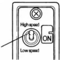
Speed change switch
2.3.
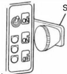
Switch lever
Lock lever
Center pin
1. Set the gear change lever and speed change switch.
Set the gear change lever and speed change switch according to the drill speed selection label. The drill speed must be changed according to the steel core bit diameter.
Drill speed selection table
| Core bit diameter (mm) | Gear change lever | Speed change switch |
| 18 to 35 | HIGH | High speed |
| 35 to 55 | LOW | High speed |
| 56 to 60 | LOW | Low speed |
Note: Be sure to stop the gear change lever in a position where the arrow on the lever and the arrow on the gear cover are aligned with each other.
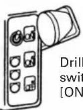
2. Make the electromagnet adhere.
When you line up the switch lever with the Electromagnet ON position, the Power lamp lights up and the electromagnet works.
3. Aligning the center pin with the punch position.
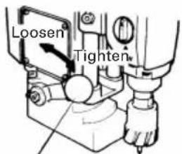
Check that the feed handle is in the manual position, then loosen the lock lever and move the main unit to bring the center pin to the punch position. After positioning the center, tighten the lock lever adequately by hand, then fasten the main unit.
4. Open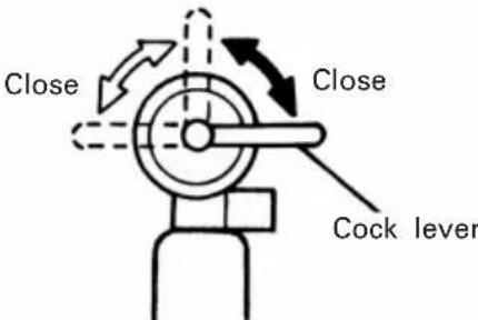 | 4. Adjust the volume of cutting solution.When you turn the cock lever to the Open direction, then turn the feed handle and push up the center pin, the cutting solution starts to flow. Adjust the flow by adjusting the cock lever angle. As a criterion for the volume of the cutting solution, the cutting chips during drilling should always be wet and should not be discolored. |
5. 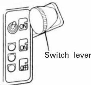 | 5. Make the electric drill turn.When you line up the switch lever with the Drill ON position, the electric drill turns. |
6.  | 6. Manually drill a hole 2-3mm deep.Turn the feed handle and gently apply propulsion to the steel core bit to drill. After bringing the bit to the work material, drill to a depth of about 2-3mm manually. |
7. Automatic Feed 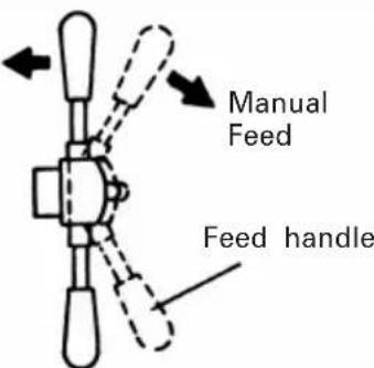 | 7. Set the feed handle to Automatic Feed.After drilling manually, stop applying propulsion, flip the feed handle toward the machine, then let go. The Auto lamp (green) lights up and the hole is drilled automatically. When the drilling is completed, the feed motor automatically turns in reverse to lift up the electric drill and stops automatically when the center pin is about 20mm from the work material. |
8. Automatic Feed 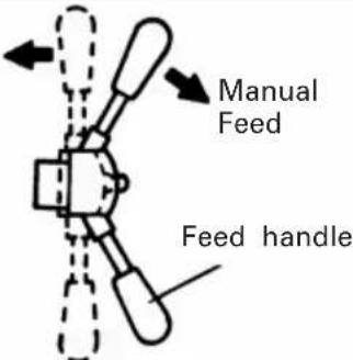 | 8. After drilling is complete, return the feed handle to Manual Feed and switch off.Return the feed handle to Manual Feed, then lower the switch lever to switch off the drill. |
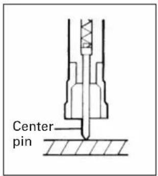
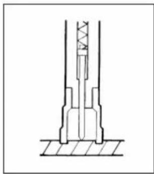
- Align the center pin with the punch position.
natural_image
Technical line drawing of a mechanical assembly with no visible text or symbols- Starts drilling while supplying cutting solution. If the center pin is pushed up, supply of lubricant will start automatically.
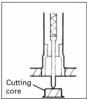
- The cutting core pops out simultaneously with completion of drilling. The center pin drops and supply of lubricant stops automatically.
Fig. 4
NOTE
Cut in manually 2-3mm, then before putting the drill into automatic, stop the feed for 1-2 seconds and allow the electric drill to idle. If you put the drill into automatic with a load still on it, the drilling may speed up excessively or the electric drill may either rise up midway through the drilling or fail to rise up after the drilling.
When using the steel core bit, always cool the tip with cutting solution. If you do not cool the steel core bit, the life of the tip is reduced. That is why this machine should not be used on ceilings or walls, in which usage the cutting solution would not reach the steel core bit tip.
If the electric drill is outside the range indicated by the arrow on the automatic feed range label and you set the feed handle to Automatic Feed, the feed stops after a few seconds. If that happens, switch off the Drill switch [ON], return the feed handle to Manual Feed and move the electric drill into the automatic feed range.
Never switch the gear change lever during the drill operation. This may damage the changing part.
- Watch out for the cutting core flying out when the drilling is complete. In particular, when working in high places, watch out for the cutting core dropping.
- Immediately after completing drilling, the electric drill rises and the feed handle turns rapidly, so be careful the rapidly turning handle does not strike your hands.
When adjusting the cock lever for automatic drilling, watch out for the feed handle. In particular, do not adjust the cock lever from immediately after the end of drilling until the electric drill stops.
The steel core will become clogged excessively if there are repeated overloads while drilling holes and may be difficult to remove. If this occurs, use a long handle wrench or other similar device to remove.
After each hole drilled, remove the cutting core and the cutting power. If cutting power remains in the steel core bit, remove it before drilling the next hole.
☐ If the cutting core is jammed in the steel core bit, remove it by knocking gently on the flange of the cutting core with a thin rod or the like.
☐ You can not drill two steel plates at once with this steel core. To drill two steel plates at once, use the multi-cutting steel core, sold separately.
9. When there is a possibility of the machine body falling.
When there is a possibility of the machine body falling due to power failure or floated electromagnet in operation at high places be sure to secure the machine body to the workpiece with the chain available as optional accessory. (Fig. 5) Use the chain as follows.
(1) Activate the electromagnet.
(2) Wind the chain round the workpiece.
(3) Connect the chain and the machine body securely with the shackle attached to the chain.
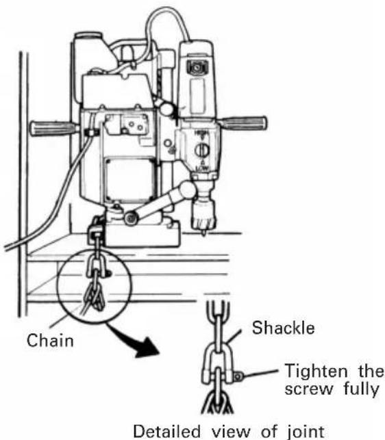
Fig. 5
ABNORMAL SYMPTOMS
This machine is microcomputer controlled. It is designed to stop in the unlikely event that the microcomputer malfunctions due to power line noise or any other cause.
If any of the following symptoms occur during use, it does not indicate a break down. Return the switch lever to the Magnet ON position, return the feed handle to Manual Feed, implement the appropriate solution, then carry out the next drilling operation.
| Symptom | Cause Solution | |
| With the switch lever in the Drill ON position, when the feed handle was moved to Automatic Feed, the electric drill stopped. | The electric drill is outside the automatic feed range. | Move the electric drill to within the automatic feed range. |
| During drilling, the electric drill rate of rotation fluctuates greatly and the drill groans or the electric drill stops and the overload lamp blinks. | The power supply voltage is too low. | Change the power supply. |
| The power supply voltage is too low due to voltage drop across the extension cord. | Stop using extension cord or use thicker ones. | |
| The flow of cutting solution is insufficient. | Increase the flow of cutting solution or remove jams midway. | |
| The tip of the steel core bit is dull. | Regrind the tip or replace it. | |
| The drill speed is too fast. | Set the gear change lever from HIGH to LOW. Otherwise set the speed change switch from high speed to low speed. | |
| Microcomputer malfunction. | Repeat the drilling operation. | |
| Midway through drilling, the elec-tric drill rises and stops. | While drilling with manual feed, the switch was set to Auto. | Do not switch to Auto while there is a load on the electric drill. |
| Microcomputer malfunction. | Repeat the drilling operation. | |
| After drilling is complete, the elec-tric drill stops without rising. | The feed handle was set to auto-matic feed while drilling with man-ual feed. | Do not switch the feed handle to automatic feed with a load on the electric drill. |
| Microcomputer malfunction. Repeat the drilling operation. | ||
MAINTENANCE AND INSPECTION
CAUTION:
Be sure to switch power OFF and disconnect the attachment plug from the power receptacle to avoid serious trouble.
1. Check the electromagnet.
If the electromagnet bottom is flawed or rusted, the attracting force is weakened. Before operation, check the bottom for any flaw or rust. When the machine is not in use, turn off the power switch, disconnect the power cord plug from the mains socket and store the machine in a dry place.
2. Adjust the play of the sliding part. (Fig. 6)
If there is play in the electric drill sliding part, the steel core bit life will be greatly reduced. If there is play, adjust it as follows.
(1) Set the switch lever to the Magnet ON position to fasten to the steel plate with the electromagnet.
(2) Set the feed handle to the manual feed position. While turning the feed handle and gently tighten the four M8 nylock screws with the supplied hexagon bar wrench.
Tighten enough that the electric drill does not fall due to its own weight.
(3) If the movement feels too hard or too easy, the adjustment is insufficient, so loosen the four screws and tighten them again evenly.
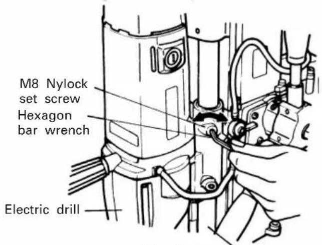
Fig. 6 Column
3. Lock lever angle adjustment.
If the grip position goes too close to the material being drilled when the lock lever is tightened (refer to item 3 on page 18), adjust the lock lever angle with the following procedure.
(1) Switch on the Power with the switch lever and fasten with the electromagnet stuck to the steel plate.
(2) Loosen the M10 nut with a wrench and remove the lock lever.
(3) Turn the lock lever in the arrow direction and install the lock lever so that angle will be appropriate.
(4) Tighten the M10 nut with the wrench.
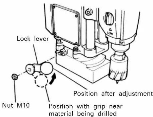
Fig. 7
4. Check the steel core bit.
If the machine is continuously operated with a dull steel core bit, the motor is overloaded, decreasing operation efficiency. Re-grind or replace the steel core bit as soon as possible.
The steel core bit is attached by winding it clockwise around the spindle. When replacing, use the two accessory wrenches (22 and 27mm) to remove. After replacement, tighten securely with the two wrenches.
The steel core bit has outer and inner blades shaped with carbide and arranged alternately. Re-grind the blades in the following dimensions.
(Re-grind the thick line parts.)
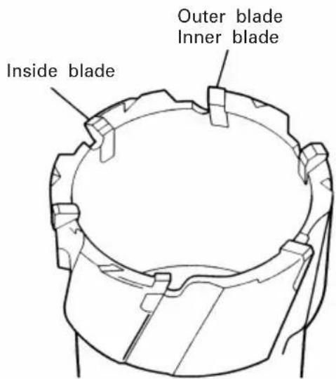
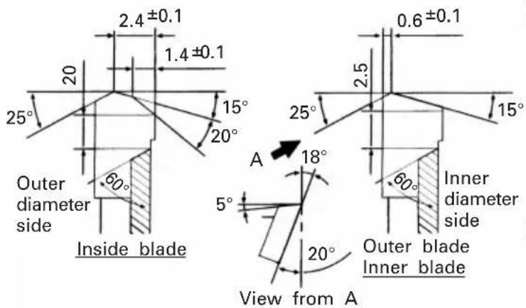
Fig. 8
5. Inspecting the center pin.
When the tip of the center pin becomes round, it will no longer fit into the punch hole, reducing the drilling precision and steel core bit life. Inspect the center pin regularly and regrind or replace.
6. Inspecting the carbon brushes (Fig. 9)
The motor employs carbon brushes which are consumable parts. Since an excessively worn carbon brush could result in motor trouble, replace the carbon brush with a new one which has the same carbon brush No. shown in the figure when it becomes worn to or near the "wear limit". In addition, always keep carbon brushes clean and ensure that they slide freely within the brush holders.
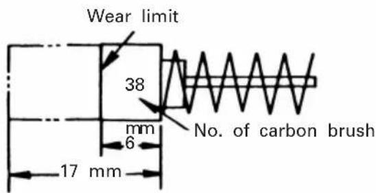
Fig. 9
○ Replacing a carbon brush
Disassemble the brush cap with a minus-head screwdriver. The carbon brush can then be easily removed.
7. Inspecting the mounting screws:
Regularly inspect all mounting screws and ensure that they are properly tightened. Should any of the screws be loose, retighten them immediately. Failure to do so could result in serious hazard.
8. Maintenance of the motor
The motor unit winding is the very "heart" of the power tool. Exercise due care to ensure the winding does not become damaged and/or wet with oil or water.
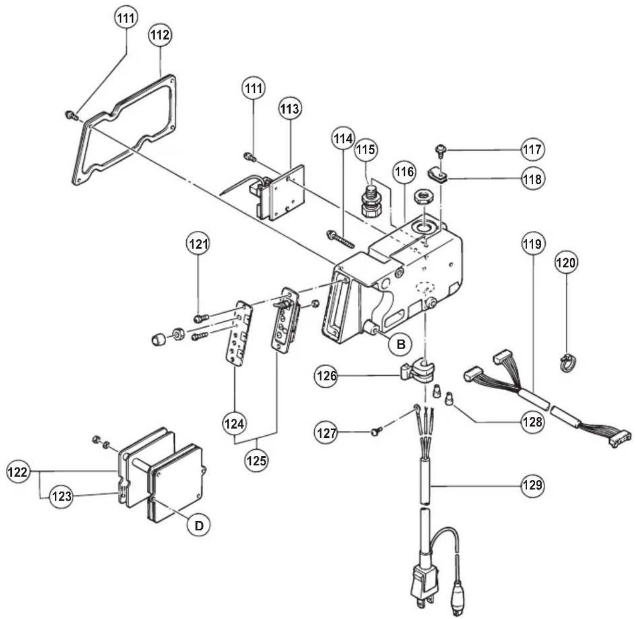
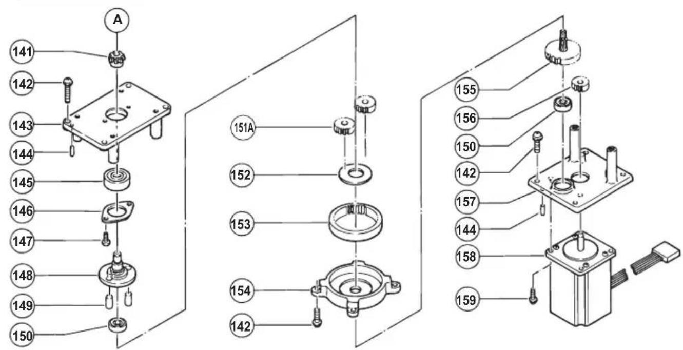
9. Service parts list
CAUTION
Repair, modification and inspection of Hitachi Power Tools must be carried out by an Hitachi Authorized Service Center.
This Parts List will be helpful if presented with the tool to the Hitachi Authorized Service Center when requesting repair or other maintenance.
In the operation and maintenance of power tools, the safety regulations and standards prescribed in each country must be observed.
MODIFICATIONS
Hitachi Power Tools are constantly being improved and modified to incorporate the latest technological advancements.
Accordingly, some parts may be changed without prior notice.
NOTE:
Due to HITACHI's continuing program of research and development, the specifications herein are subject to change without prior notice.

natural_image
Line drawing of a quill pen with inkwell (no text or symbols)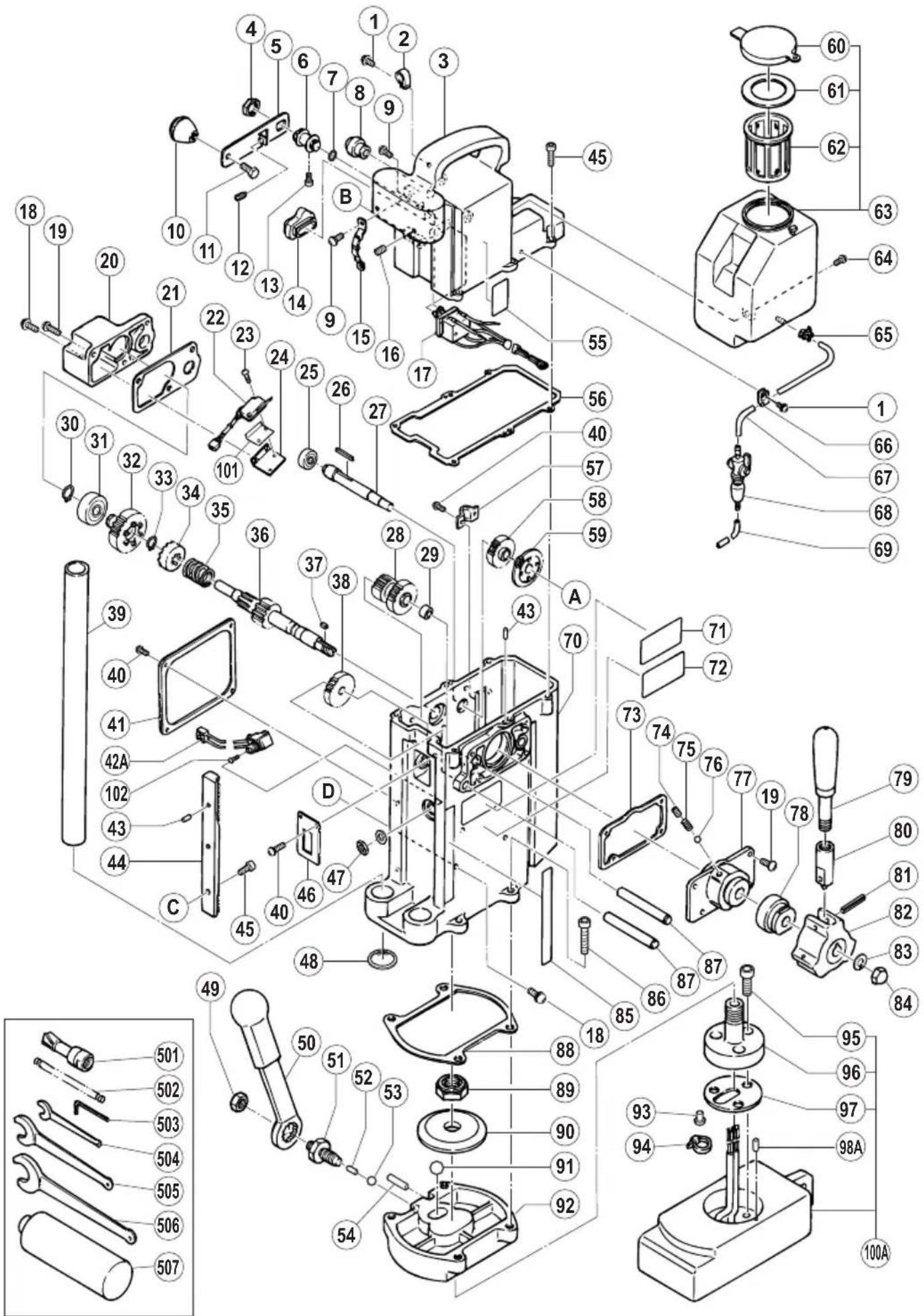
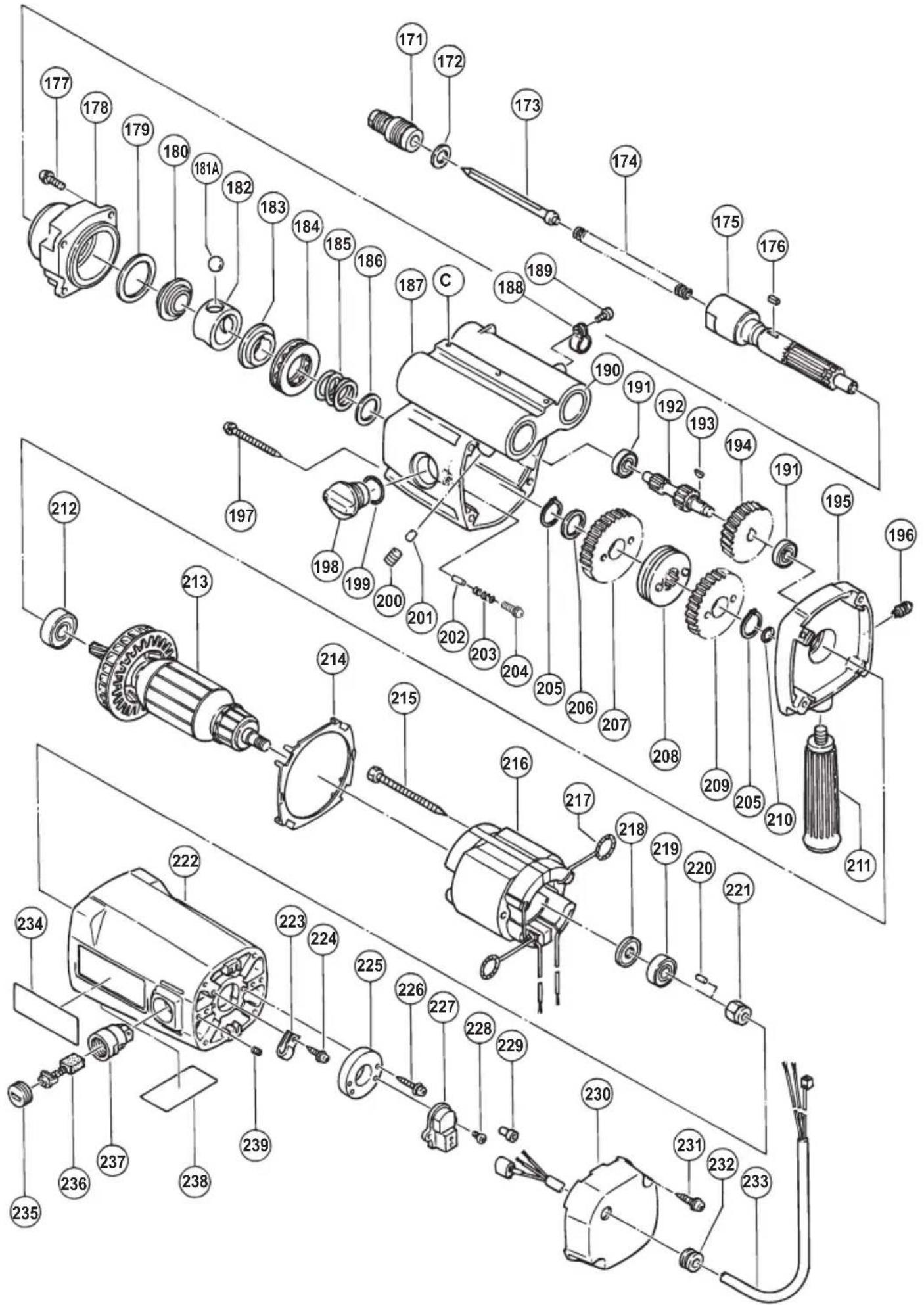
| ITEM NO. | PART NAME | Q'TY |
| 176 | FEATHER KEY 3X3X10 | 1 |
| 177 | SEAL LOCK SCREW (W/SP. WASHER) M5X16 | 4 |
| 178 | FRONT COVER | 1 |
| 179 | WASHER (B) | 1 |
| 180 | BALL SLEEVE (B) | 1 |
| 181A | STEEL BALL D14.29 | 3 |
| 182 | RETAINER (A) | 1 |
| 183 | BALL SLEEVE (A) | 1 |
| 184 | THRUST BEARING (51106) | 1 |
| 185 | SPRING (A) | 1 |
| 186 | WASHER (A) | 1 |
| 187 | GEAR COVER ASS'Y | 1 |
| 188 | CLAMP | 1 |
| 189 | SEAL LOCK HEX. SOCKET HD. BOLT M4X8 | 1 |
| 190 | METAL (F) | 4 |
| 191 | BALL BEARING 608VVC2PS2L | 2 |
| 192 | SECOND PINION | 1 |
| 193 | WOODRUFF KEY 3X10 | 1 |
| 194 | FIRST GEAR | 1 |
| 195 | INNER COVER ASS'Y | 1 |
| 196 | NIPPLE M5 | 1 |
| 197 | TAPPING SCREW (W/SP, WASHER) D5X55 | 4 |
| 198 | SHIFT LEVER ASS'Y | 1 |
| 199 | O-RING (S-22) | 1 |
| 200 | NYLOCK HEX. SOCKET SET SCREW M8X8 | 4 |
| 201 | COLUMN BUSHING | 4 |
| 202 | NEEDLE D3.5 | 1 |
| 203 | VALVE SPRING | 1 |
| 204 | SEAL LOCK SCREW (W/WASHERS) M5X8 | 1 |
| 205 | RETAINING RING FOR D20 SHAF | 2 |
| 206 | SLEEVE | 1 |
| 207 | LOW SPEED GEAR | 1 |
| 208 | SLIDER (A) | 1 |
| 209 | HIGH SPEED GEAR | 1 |
| 210 | O-RING (1AP-10) | 1 |
| 211 | SIDE HANDLE | 2 |
| 212 | BALL BEARING 6201VVCMPS2L | 1 |
| 213 | ARMATURE | 1 |
| 214 | FAN GUIDE | 1 |
| 215 | HEX. HD. TAPPING SCREW D5X70 | 2 |
| 216 | STATOR ASS'Y | 1 |
| 217 | BRUSH TERMINAL | 2 |
| 218 | DUST WASHER (A) | 1 |
| 219 | BALL BEARING 6000VVCMPS2L | 1 |
| 220 | BEARING LOCK | 1 |
| 221 | MAGNET | 1 |
| 222 | HOUSING ASS'Y | 1 |
| 223 | WIRE CLIP | 1 |
| 224 | TAPPING SCREW (W/WASHER) D4X12 | 1 |
| 225 | SPACER (A) | 1 |
| 226 | TAPPING SCREW (W/WASHER) D4X20 | 2 |
| 227 | MAGNET PICK UP CASE | 1 |
| 228 | BIND SCREW M4X6 | 2 |
| 229 | CONNECTOR 50091 | 2 |
| 230 | MOTOR COVER | 1 |
| 231 | TAPPING SCREW (W/FLANGE) D5X16 | 2 |
| 232 | CORD ARMOR | 1 |
| 233 | PICK UP CABLE | 1 |
| 234 | HITACHI LABEL | 1 |
| 235 | BRUSH CAP | 2 |
| 236 | CARBON BRUSH | 2 |
| 237 | BRUSH HOLDER | 2 |
| 238 | SETTING LABEL | 1 |
| 239 | HEX. SOCKET SET SCREW M4X5 | 2 |
| 501 | STEEL CORE BIT (N) D22 T50 | 1 |
| 502 | SPRING FOR THIN PLATE | 1 |
| 503 | HEX. BAR WRENCH 4MM | 1 |
| 504 | WRENCH 13MM | 1 |
| 505 | WRENCH 22MM | 1 |
| 506 | WRENCH 27MM | 1 |
| 507 | CUTTING OIL (500CC) | 1 |
| ITEM NO. | PART NAME | Q'TY |
| 73 | SHEET PACKING (A) | 1 |
| 74 | CAP SCREW | 3 |
| 75 | SPRING (A) | 3 |
| 76 | STEEL BALL D6.35 | 3 |
| 77 | HANDLE BOSS HOLDER (B) | 1 |
| 78 | HANDLE BOSS HOLDER (A) | 1 |
| 79 | HANDLE ASS'Y | 3 |
| 80 | HANDLE HOLDER | 3 |
| 81 | ROLL PIN D6X25 | 3 |
| 82 | HANDLE BOSS | 1 |
| 83 | SPRING WASHER M10 | 1 |
| 84 | CAP NUT M10 | 1 |
| 85 | MARK PLATE (A) | 1 |
| 86 | SEAL LOCK HEX, SOCKET HD, BOLT M8X25 | 4 |
| 87 | GEAR SHAFT (B) | 2 |
| 88 | SHEET PACKING (D) | 1 |
| 89 | U-NUT M20 | 1 |
| 90 | LOCK PLATE (A) | 1 |
| 91 | STEEL BALL D12.7 | 2 |
| 92 | BASE | 1 |
| 93 | CONNECTOR 50091 | 3 |
| 94 | WIRE BAND | 1 |
| 95 | SEAL LOCK HEX, SOCKET HD, BOLT M8X12 | 3 |
| 96 | RADIAL SHAFT (A) | 1 |
| 97 | SEAL PACKING | 1 |
| 98A | SLOTTED PIN | 1 |
| 100A | MAGNET ASS'Y | 1 |
| 101 | INSULATOR (S) | 1 |
| 102 | MACHINE SCREW (STAINLESS) M3X10 | 1 |
| 111 | SEAL LOCK SCREW (W/SP, WASHER) M4X10 | 6 |
| 112 | PANEL (B) | 1 |
| 113 | TRIAC CT | 1 |
| 114 | SEAL LOCK SCREW (W/SP, WASHER) M5X30 | 3 |
| 115 | CORD STOPPER (B) | 1 |
| 116 | SWITCH BOX | 1 |
| 117 | SEAL LOCK SCREW (W/WASHERS) M4X10 | 1 |
| 118 | WIRE CLIP | 1 |
| 119 | CABLE | 1 |
| 120 | WIRE BAND | 1 |
| 121 | MACHINE SCREW (W/WASHERS) M4X10 | 2 |
| 122 | CONTROLLER ASS'Y | 1 |
| 123 | FUSE (2A) | 1 |
| 124 | SWITCH PANEL | 1 |
| 125 | SWITCH PANEL ASS'Y | 1 |
| 126 | CORD STOPPER | 1 |
| 127 | MACHINE SCREW (BRASS) M4X6 | 1 |
| 128 | CONNECTOR 50092 | 5 |
| 129 | CORD | 1 |
| 141 | PINION | 1 |
| 142 | SEAL LOCK SCREW (W/SP, WASHER) M5X16 | 12 |
| 143 | INNER COVER (C) | 1 |
| 144 | PIN D4X12 | 4 |
| 145 | BALL BEARING 6001VVCMPS2L | 1 |
| 146 | BEARING COVER (B) | 1 |
| 147 | SLOTTED HD, SCREW (SEAL LOCK) M4X10 | 2 |
| 148 | FLANGE SHAFT (A) | 1 |
| 149 | NEEDLE ROLLER | 2 |
| 150 | BALL BEARING 626VVC2PS2L | 2 |
| 151A | IDLE GEAR SET | 2 |
| 152 | WASHER | 1 |
| 153 | RING GEAR | 1 |
| 154 | GEAR HOLDER | 1 |
| 155 | FEED SECOND PINION | 1 |
| 156 | FIRST PINION | 1 |
| 157 | INNER COVER (D) | 1 |
| 158 | FEED MOTOR | 1 |
| 159 | SEAL LOCK SCREW (W/SP, WASHER) M4X12 | 4 |
| 171 | CENTER PIN GUIDE | 1 |
| 172 | THRUST WASHER | 1 |
| 173 | CENTER PIN | 1 |
| 174 | SPRING (STANDARD) | 1 |
| 175 | SPINDLE | 1 |
| ITEMNO. | PART NAME Q'TY | |
| 1 SEAL LOCK SCREW (W/WASHERS) M4X10 2 | ||
| 2 WIRE CLIP 1 | ||
| 3 COLUMN COVER 1 | ||
| 4 SPECIAL NUT M16 1 | ||
| 5 SWITCH LEVER (A) 1 | ||
| 6 SLEEVE 1 | ||
| 7 O-RING (P-9) 1 | ||
| 8 RUBBER BUSHING (B) 1 | ||
| 9 SEAL LOCK SCREW (W/SP. WASHER) M4X10 4 | ||
| 10 GRIP 1 | ||
| 11 SEAL LOCK HIGH TENSION BOLT M8X16 1 | ||
| 12 PLUNGER 1 | ||
| 13 HEX, SOCKET HD, BOLT M5X6 1 | ||
| 14 RUBBER BUSHING (A) 1 | ||
| 15 GUIDE PLATE (A) 1 | ||
| 16 SEAL LOCK HEX, SOCKET SET SCREW M6X6 | 2 | |
| 17 ROTARY SWITCH | 1 | |
| 18 SEAL LOCK SCREW (W/WASHERS) M4X16 4 | ||
| 19 SEAL LOCK SCREW (W/SP. WASHER) M5X16 7 | ||
| 20 SIDE COVER (A) | 1 | |
| 21 SHEET PACKING (E) | 1 | |
| 22 SWITCH FOR AUTOMATIC FEED | 1 | |
| 23 SEAL LOCK SCREW M3X14 | 2 | |
| 24 SWITCH PLATE (A) | 1 | |
| 25 BALL BEARING 608VVC2PS2L | 1 | |
| 26 FEATHER KEY 2.5X2.5X28 | 1 | |
| 27 GEAR SHAFT (A) | 1 | |
| 28 FEED PINION (C) | 1 | |
| 29 SLEEVE (A) | 1 | |
| 30 RETAINING RING FOR D15 SHAFT | 1 | |
| 31 BALL BEARING 6002VVC MPS2L | 1 | |
| 32 CLUTCH GEAR | 1 | |
| 33 RETAINING RING FOR D12 SHAFT (10 PCS.) | 1 | |
| 34 CLUTCH (B) | 1 | |
| 35 CLUTCH SPRING 1 | ||
| 36 HANDLE SHAFT (A) | 1 | |
| 37 FEATHER KEY 4X4X10 | 1 | |
| 38 FEED PINION (D) | 1 | |
| 39 COLUMN | 2 | |
| 40 SEAL LOCK SCREW (W/SP. WASHER) M4X10.8 | ||
| 41 PANEL (D) | 1 | |
| 42A | MICRO SWITCH SET | 1 |
| 43 PIN D4X12 (10 PCS.) | 3 | |
| 44 RACK | 1 | |
| 45 SEAL LOCK HEX, SOCKET HD, BOLT M5X16 | 8 | |
| 46 COVER PLATE | 1 | |
| 47 DUST NUT | 1 | |
| 48 RETAINING RING FOR D26 HOLE | 2 | |
| 49 NUT M10 | 1 | |
| 50 LOCK LEVER | 1 | |
| 51 LOCK SHAFT ASS'Y | 1 | |
| 52 NEEDLE D8X12 | 1 | |
| 53 STEEL BALL D9.53 | 1 | |
| 54 ROLL PIN D6X28 | 1 | |
| 55 MARK PLATE (B) | 1 | |
| 56 SHEET PACKING (F) | 1 | |
| 57 CORD CLIP | 1 | |
| 58 FEED PINION (A) | 1 | |
| 59 GEAR | 1 | |
| 60 CAP | 1 | |
| 61 RUBBER PACKING | 1 | |
| 62 FILTER | 1 | |
| 63 | OIL TANK (B) ASS'Y | 1 |
| 64 | MACHINE SCREW (W/WASHERS) M4X12 | 1 |
| 65 | WIRE CLIP 1 | |
| 66 | WIRE CLIP 1 | |
| 67 | URETHANE TUBE (I.D.4XT1X310) | 1 |
| 68 | TUBE (I.D.4XT1X185) | 1 |
| 69 | OIL VALVE | 1 |
| 70 | BODY ASS'Y | 1 |
| 71 | NAME PLATE | 1 |
| 72 | CAUTION PLATE | 1 |
natural_image
Line drawing of a quill pen with inkwell, no text or symbols present
natural_image
Line drawing of a quill pen with inkwell (no text or symbols)服务中心
日立工机商业(中国)有限公司
上海市长宁区遵义路100号
虹桥上海城B栋2686-2688室
制造商
日立工机株式会社
日本国茨城县常陆那珂市
Hitachi Koki Co., Ltd.
710
Code No. C99069121 N
Printed in Japan