HITACHI DW25EF(SRP) - Drill

DW25EF(SRP) - Drill HITACHI - Free user manual and instructions

Find the device manual for free DW25EF(SRP) HITACHI in PDF.

📄 128 pages English EN Download 💬 AI Question 10 questions ⚙️ Specs
Notice HITACHI DW25EF(SRP) - page 2
View the manual : Deutsch DE English EN
Pick your language and provide your email: we'll send you a specifically translated version.
Product Type Corded Electric Drill
Model DW25EF(SRP)
Brand Hitachi (Metabo HPT)
Power Source AC Corded (100-120V, 50/60Hz)
Input Power 650 W
No-Load Speed 0-2800 RPM (Variable)
Chuck Type Keyless, 13 mm (1/2 in)
Drilling Capacity (Steel) 13 mm (1/2 in)
Drilling Capacity (Wood) 25 mm (1 in)
Weight 1.6 kg (3.5 lbs)
Dimensions (L x W x H) 280 x 65 x 200 mm (11 x 2.6 x 7.9 in)
Main Functions Drilling, Screwdriving, Hammer Drilling (if equipped)
Variable Speed Trigger Yes, with lock-on button
Forward/Reverse Switch Yes
Maintenance Clean vents regularly; lubricate chuck as needed; replace carbon brushes when worn
Safety Features Double insulation, safety trigger lock, keyless chuck with auto-lock
Spare Parts & Repairability Chuck, carbon brushes, switch, cord set available; design allows easy disassembly
General Information Designed for DIY and light professional use; includes side handle and depth gauge

Frequently Asked Questions - DW25EF(SRP) HITACHI

How do I change the drill bit on the Hitachi DW25EF(SRP)?
Turn the chuck ring counterclockwise to open the jaws. Insert the bit, then tighten the chuck by turning the ring clockwise. Ensure the bit is centered and secure. For keyless chucks, no key is needed.
What is the maximum drilling capacity of the DW25EF(SRP)?
The maximum drilling capacity in steel is 13 mm (1/2 in), and in wood it is 25 mm (1 in). Use appropriate bits for materials.
Can I use this drill for screwdriving?
Yes, the DW25EF(SRP) has a variable speed trigger that allows controlled screwdriving. Use a screwdriver bit and set the torque clutch (if available) to prevent overdriving.
How do I adjust the speed of the drill?
The speed is controlled by the trigger pressure: light pressure for low speed, full pressure for high speed. There is also a speed selector switch (if equipped) for high/low gear ranges.
What safety precautions should I take when using the drill?
Always wear safety glasses and hearing protection. Secure your workpiece. Keep hands away from rotating parts. Unplug the drill when changing bits. Use the side handle for control.
How do I maintain the Hitachi DW25EF(SRP) drill?
Clean the air vents with a soft brush. Periodically lubricate the chuck with light oil. Check carbon brushes every 50 hours of use and replace if worn. Store in a dry place.
The drill is sparking at the brushes. Is this normal?
Some sparking is normal due to brush commutation. However, excessive sparking indicates worn brushes or a dirty commutator. Inspect and replace brushes if needed. Clean the commutator with a suitable solvent.
Can I use a hammer function for masonry drilling?
If your model is equipped with a hammer function, you can drill into brick or concrete using carbide-tipped bits. Always apply moderate pressure and let the tool do the work.
How do I replace the carbon brushes?
Unplug the drill. Remove the brush caps on the motor housing. Slide out the old brushes and insert new ones (same size). Ensure they seat properly against the commutator. Replace caps and test.
Where can I find spare parts for the DW25EF(SRP)?
Spare parts such as chucks, brushes, switches, and cords are available through Hitachi/Metabo HPT service centers or authorized online retailers. Use genuine parts for safety and performance.

User questions about DW25EF(SRP) HITACHI

0 question about this device. Answer the ones you know or ask your own.

Ask a new question about this device

The email remains private: it is only used to notify you if someone responds to your question.

No questions yet. Be the first to ask one.

Download the instructions for your Drill in PDF format for free! Find your manual DW25EF(SRP) - HITACHI and take your electronic device back in hand. On this page are published all the documents necessary for the use of your device. DW25EF(SRP) by HITACHI.

USER MANUAL DW25EF(SRP) HITACHI

DW25EA (SN)/DW25EA (S) DW25EB (SK)/DW25EB (SKN) DW25EB (SR)/DW25EB (SRN) DW25EC (SKN)/DW25ED (KP) DW25ED (KPN)/DW25EF (SK) DW25EF (SKN)/DW25EF (SR) DW25EF (SRN)

Owner's manual Bedienungsanleitung ΟΔΗΓΙΕΣ ΧΡΗΣΗΣ Podręcznik użytkownika Használati utasítás Návod k použití Kullanım kılavuzu Instrucțiuni de utilizare Navodila za uporabo

HITACHI

DW25EA (SN)/DW25EA (S) DW25EB (SK)/DW25EB (SKN) DW25EB (SR)/DW25EB (SRN) DW25EC (SKN)/DW25ED (KP) DW25ED (KPN)/DW25EF (SK) DW25EF (SKN)/DW25EF (SR) DW25EF (SRN)

Icon of a person reading a book inside a circle (no text or symbols)

Simple line drawing of an open book and a lowercase 'i' symbol, no text or labels present

Read the manual carefully before operating this machine.

Owner's manual

HITACHI DW25EF(SRP) - HITACHI - 3

WARNING

The engine exhaust from this product contains chemicals known to the State of California to cause cancer, birth defects and other reproductive harm.

Icon of a person reading a book inside a circle (no text or symbols)

Simple line icon showing an open book and a lowercase 'i' symbol, no text or labels present.

It is important that you read, fully understand and observe the following safety precautions and warnings. Careless or improper use of the unit may cause serious or fatal injury.

Warning symbol with exclamation mark inside triangle

Read, understand and follow all warnings and instructions in this manual and on the unit.

Circular icon with a stylized face wearing sunglasses and a helmet, enclosed in a circle (no text or symbols)

Always wear eye, head and ear protectors when using this unit.

Two vertical symbols with geometric markings: a horizontal line and a vertical line, both containing small black shapes.

Explains choke position. Upper sign indicates choke closed and the lower fully open.

HITACHI DW25EF(SRP) - WARNING - 6

Do not touch the bit when running the engine.

Do not touch the bit when running the engine.

Before using your machine

  • Read the manual carefully.
  • Check that the cutting equipment is correctly assembled and adjusted.
  • Start the unit and check the carburetor adjustment. See "Maintenance".

Declaration of conformity

We, Nikko Tanaka Engineering Co., Ltd., 3-4-29 Tsudanuma, Narashino, Chiba, Japan

Declare under our sole responsibility that the product, Engine drill model

DW25EA (SN)/DW25EA (S)

DW25EB (SK)/DW25EB (SKN)

DW25EB (SR)/DW25EB (SRN)

DW25EC (SKN)/DW25ED (KP)

DW25ED (KPN)/DW25EF (SK)

DW25EF (SKN)/DW25EF (SR)

DW25EF (SRN)

to which this declaration relates is in conformity with the essential safety requirements of directives.

98/37/EC, 89/336/EEC, 2000/14/EC

The following standards have been taken into consideration

ISO 3864 (EN ISO 12100-1/2)

Manufactured at :

Chiba, Japan

on the

01/01/2008

Signature:

HITACHI DW25EF(SRP) - Declaration of conformity - 1

Yoshio Osada

Serial No. up from

E180001

Position :

Director

Index

What is what? 4

Warnings and safety instructions 5

Assembly procedures 6

Operating procedures 6

Maintenance 10

Specifications 12

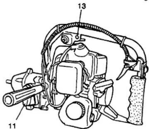
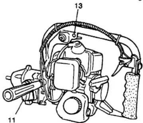
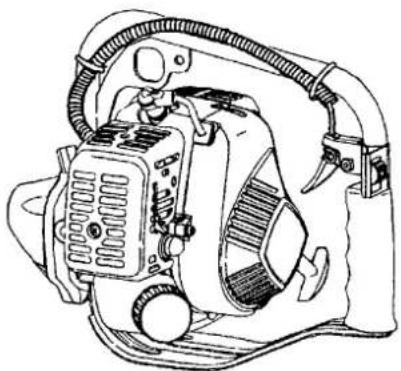
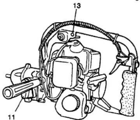
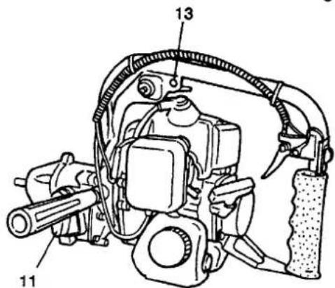
1. What is what?

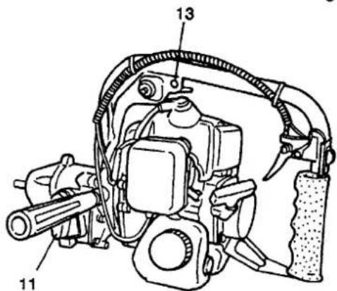
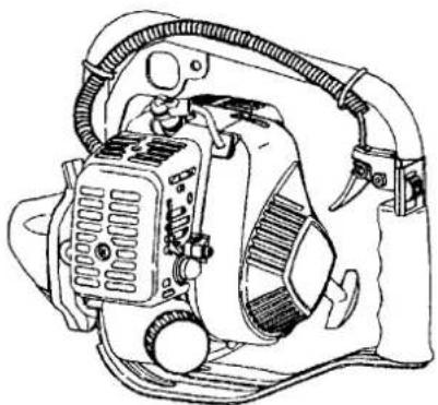
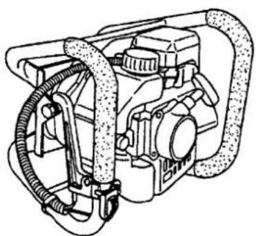
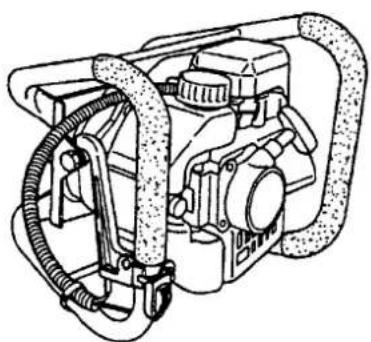
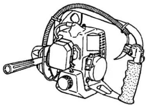
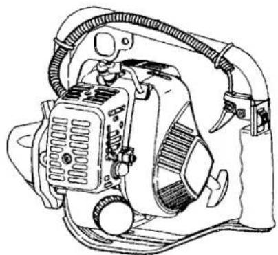
Since this manual covers several models, there may be some difference between pictures and your unit. Use the instructions that apply to your unit.

  1. Handle
  2. Plug cap
  3. Ignition switch
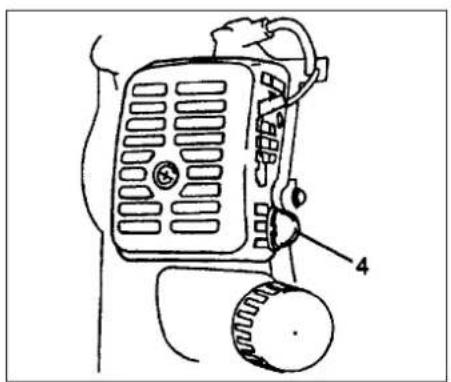
  4. Muffler
  5. Chuck unit
  6. Throttle trigger
  7. Recoil starter
  8. Gear case
  9. Fuel cap
  10. Fuel tank
  11. Shift lever
  12. Air cleaner
  13. Hole for strap

Labeled diagram of a power drill with numbered parts for identification

Technical diagram of a mechanical device with numbered components labeled 11, 13, and 14

Technical line drawing of a mechanical device with hoses and components (no text or symbols)

Line drawing of a mechanical device with hoses and control knobs (no text or symbols)

Technical line drawing of a mechanical pump assembly (no text or labels)

2. Warnings and safety instructions

Operator safety

• Always wear a safety face shield or goggles.
• Always wear heavy, long pants, boots and gloves. Do not wear loose clothing, jewelry, short pants, sandals or go barefoot. Secure hair so it is above shoulder length.
- Do not operate this unit/machin when you are tired, ill or under the influence of alcohol, drugs or medication.
- Never let a child or inexperienced person operate the machine.
- Wear hearing protection.
- Never start or run the engine inside a closed room or building. Breathing exhaust fumes can kill.
- Keep handles free of oil and fuel.
- Keep hands away from drilling equipment.
- Do not grab or hold the unit by the drilling equipment.
- When the unit is turned off, make sure the drilling attachment has stopped before the unit is set down.
- When operation is prolonged, take a break from time to time so that you may avoid possible whitefinger disease which is caused by vibration.

Unit / machine safety

  • Inspect the entire unit/machine before each use. Replace damaged parts. Check for fuel leaks and make sure all fasteners are in place and securely tightened.
  • Replace parts that are cracked, chipped or damaged in any way before using the unit/machine.
  • Keep others away when making carburetor adjustments.
  • Use only accessories as recommended for this unit/machine by the manufacturer.

WARNING!

Never modify the unit/machine in any way. Do not use your drilling tool for any job except that for which it is intended.

Fuel safety

  • Mix and pour fuel outdoors and where there are no sparks or flames.
  • Use a container approved for fuel.
  • Do not smoke or allow smoking near fuel or the unit/machine or while using the unit/machine.
  • Wipe up all fuel spills before starting engine.

  • Move at least 3 m away from fueling site before starting engine.

  • Stop engine before removing fuel cap.
  • Empty the fuel tank before storing the unit/machine. It is recommended that the fuel be emptied after each use. If fuel is left in the tank, store so fuel will not leak.
  • Store unit/machine and fuel in area where fuel vapors cannot reach sparks or open flames from water heaters, electric motors or switches, furnaces. etc.

WARNING!

Antivibration systems do not guarantee that you will not sustain whitefinger disease or carpal tunnel syndrome.

Therefore, continual and regular users should monitor closely the condition of their hands and fingers. If any of the above symptoms appear, seek medical advice immediately.

Drilling safety

  • Do not drill any material other than that for which is intended.
  • Inspect the area to be drilled before each use. Remove objects which can be thrown or become entangled.
  • For respiratory protection, wear an aerosol protection mask when drilling the area after insecticide is scattered.
  • Keep others including children, animals, bystanders and helpers outside the 5 m hazard zone. Stop the engine immediately if you are approached.
  • Hold the unit/machine firmly with both hands.
  • Keep firm footing and balance. Do not over-reach.
  • Keep all parts of your body away from the muffler and drilling attachment when the engine is running.

Maintenance safety

  • Maintain the unit/machine according to recommended procedures.
  • Disconnect the spark plug before performing maintenance except for carburetor adjustments.
  • Keep others away when making carburetor adjustments.
  • Use only genuine HITACHI replacement parts as recommended by the manufacturer.

Transport and storage

  • Carry the unit/machine by hand with the engine stopped and the muffler away from your body.
  • Allow the engine to cool, empty the fuel tank, and secure the unit/machine before storing or transporting in a vehicle.
  • Empty the fuel tank before storing the unit/machine, It is recommended that the fuel be emptied after each use. If fuel is left in the tank, store so fuel will not leak.
  • Store unit/machine out of the reach of children.
  • Clean and maintenance the unit carefully and store it in a dry place
  • Make sure engine switch is off when transporting or storing.
  • When transporting in a vehicle, or storage cover bit with bit cover or rug.

If situations occur which are not covered in this manual, take care and use. Contact HITACHI dealer if you need assistance. Pay special attention to statements preceded by the following words:

WARNING!

Indicates a strong possibility of severe personal injury or loss of life, if instructions are not followed.

CAUTION!

Indicates a possibility of personal injury or equipment damage, if instructions are not followed.

NOTE!

Helpful information for correct function and use.
Technical diagram of a mechanical assembly with numbered components labeled 1, 2, and 3

4

Technical line drawing of a mechanical assembly with no visible text or symbols

Fig.1-1 Fig.1-1C Fig.1-1B
Technical line drawing of a mechanical assembly with a tool and housing (no text or symbols)

Fig.1-1D

Line drawing of a fuel can pouring liquid into a container with an icon of fuel (no text or symbols)

Fig.2-1

3. Assembly procedures

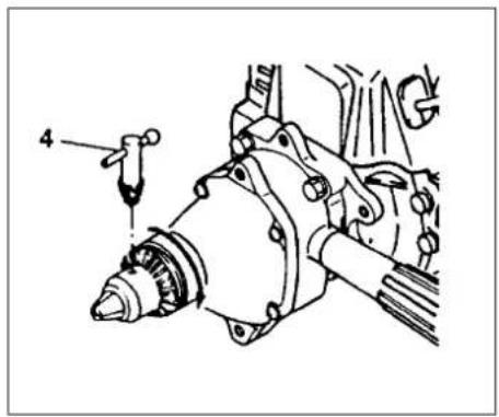
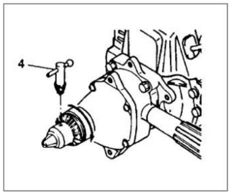
Assembling (Fig. 1-1, 1B, 1C)

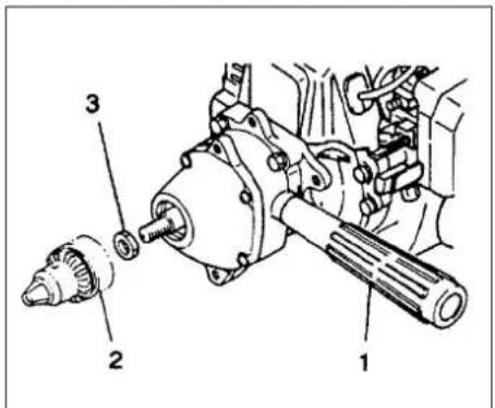
  1. Assemble the handle (1) witch is supplied with the unit to the gear case.
  2. Screw the chuck unit (2) into the drive shaft (clockwise) after the collar B (3) has been installed.

NOTE!

The collar B (3) is not used on Model DW25EB/DW25EC/DW25ED/DW25EF

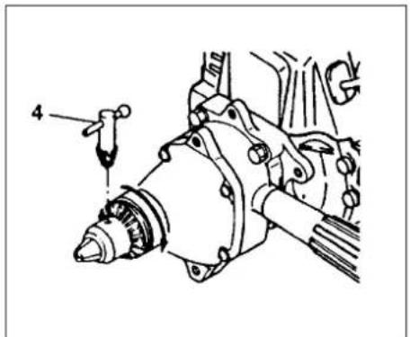
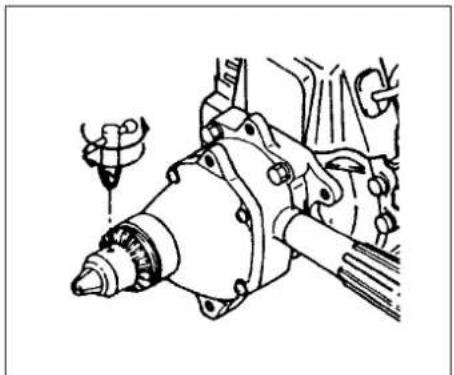
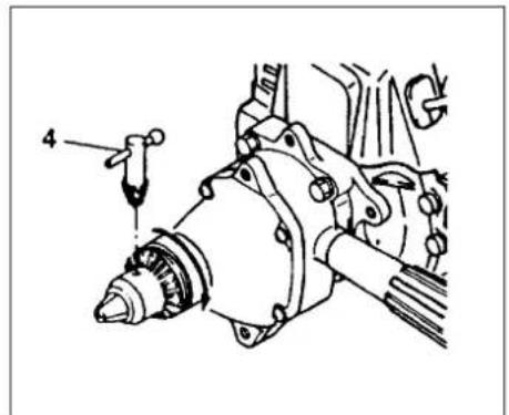
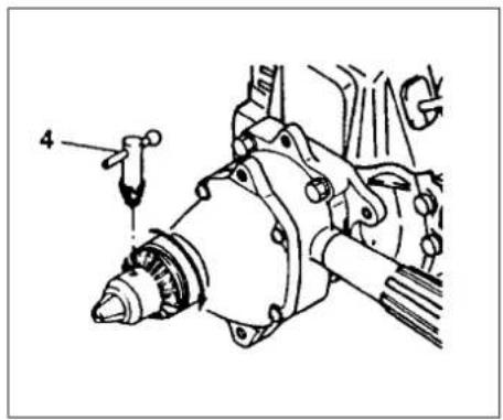
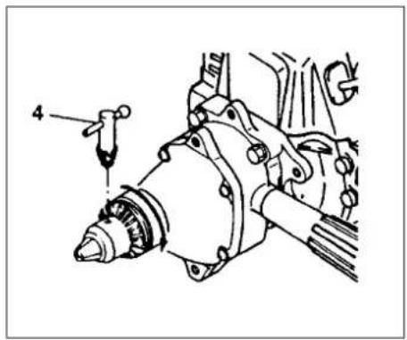
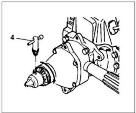
  1. Insert the drill bit to be used after opening the chuck by the chuck handle (4) and tighten the chuck by the handle.

NOTE!

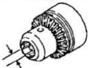
If the keylesschuck is equipped, loosen chuck and insert drill bit. Then tighten chuck by turning clockwise till making "click" noise (Fig.1-1D)

Selection of a Suitable Bit

Choose a drill bit according to material to be drilled.

4. Operating procedures

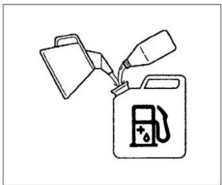
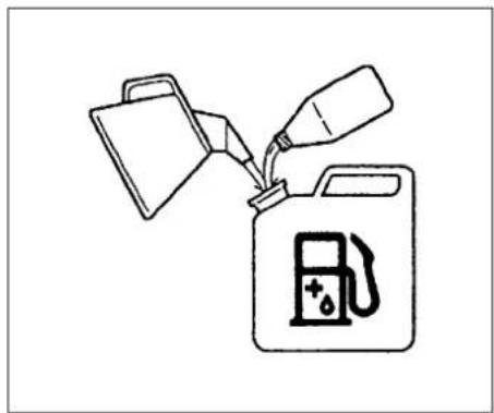
Fuel (Fig. 2-1)

HITACHI DW25EF(SRP) - Operating procedures - 1

WARNING!

The power drill is equipped with a two-stroke engine. Always run the engine on fuel, which is mixed with oil. Provide good ventilation, when fueling or handling fuel.

Fuel

• Always use branded 89 octane unleaded gasoline.
- Use genuine two-cycle oil or use a mix between 25:1 to 50:1, please consult the oil bottle for the ratio or HITACHI dealer.
• Only for the state of California at 50:1.
- If genuine oil is not available, use an antioxidant added quality oil expressly labeled for air-cooled 2-cycle engine use(JASO FC GRADE OIL or ISO EGC GRADE). Do not use BIA or TCW (2-stroke water-cooling type) mixed oil.
- Never use multi-grade oil (10 W/30) or waste oil.
• Always mix fuel and oil in a separate clean container.

Always start by filling half the amount of fuel, which is to be used. Then add the whole amount of oil. Mix (shake) the fuel mixture. Add the remaining amount of fuel.

Mix (shake) the fuel-mix thoroughly before filling the fuel tank.

Fueling

HITACHI DW25EF(SRP) - Fueling - 1

WARNING!

•Always shut off the engine before refueling.
- Slowly open the fuel tank, when filling up with fuel, so that possible over-pressure disappears.
- Tighten the fuel cap carefully, after fueling.
- Always move the unit at least 3m (10 ft.) from the fueling area before starting.

Before fueling, clean the tank cap area carefully, to ensure that no dirt falls into the tank. Make sure that the fuel is well mixed by shaking the container, before fueling.

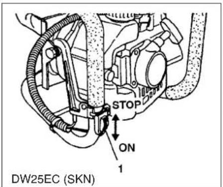
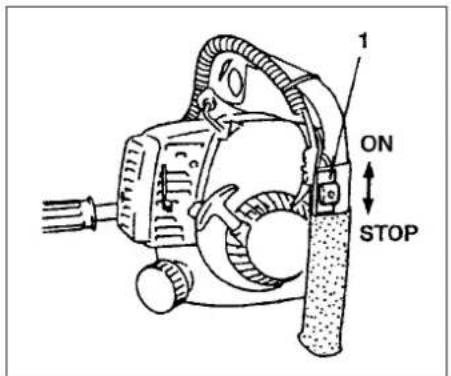
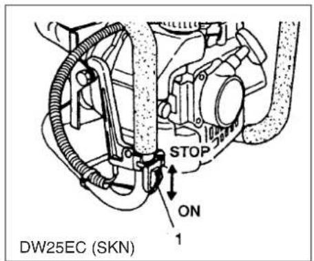
ON STOP 1

STOP ON 1 DW25EC (SKN)

Technical diagram of a mechanical assembly with numbered components labeled 4 and 5

Fig. 2-2 Fig. 2-2C Fig. 2-2B
Technical diagram of a device with labeled parts, showing a motor and wheel assembly.

Fig. 2-2D

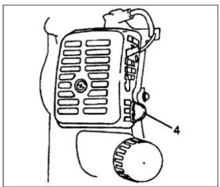
CLOSED RUN 4

Fig. 2-2E Fig. 2-3

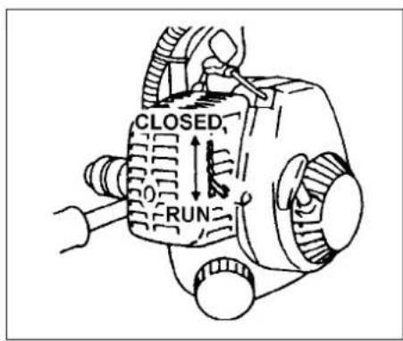
CLOSED RUN

CLOSED NO TACO RUN

Fig. 2-3B

Three technical line drawings of automotive engine components, showing internal assemblies without any text or symbols.

Fig. 2-4

Starting

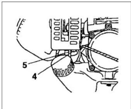
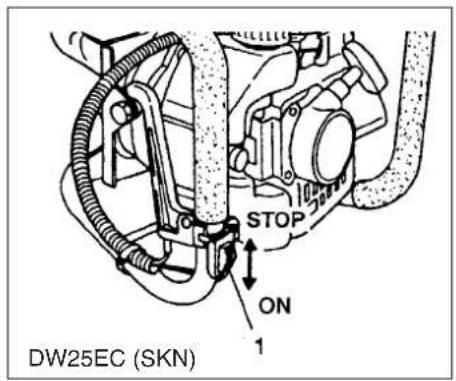
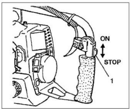
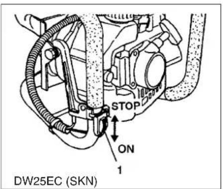
  1. Set ignition switch (1) to ON position. (Fig. 2-2, 2B)
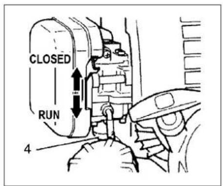
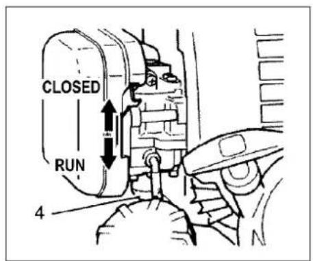
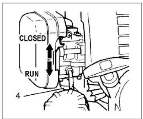
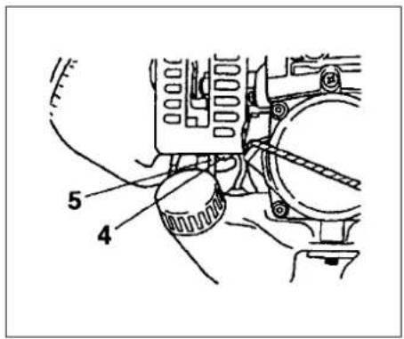
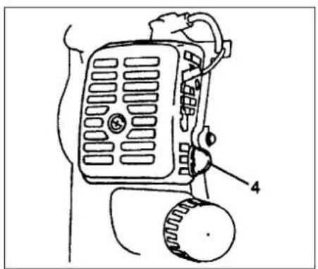
    *Push priming bulb (4) several times so that fuel flows through the bulb or return pipe(5). (If so equipped) (Fig. 2-2C, 2D, 2E)
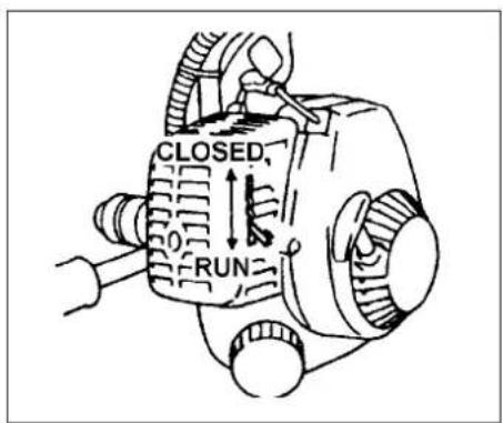
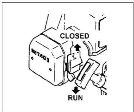
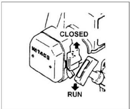
  2. Set choke lever to CLOSED position. (Fig. 2-2E, 3, 3B)
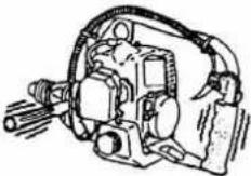
  3. Pull recoil starter briskly, taking care to keep the handle in your grasp and not allowing it to snap back. (Fig. 2-4)
  4. When you hear the engine want to start, return choke lever to RUN position (open). Then pull recoil starter briskly again. (Fig. 2-2E, 3, 3B)

NOTE!

If engine does not start, repeat procedures from 2 to 4.
5. After starting engine, allow the engine about 2-3 minutes to warm up before subjecting it to any load.
Line drawing of hands operating a mechanical device with hoses and connectors (no text or symbols)

Line drawing of hands holding a mechanical component with hoses and gears (no text or symbols)

Fig. 2-5 Fig. 2-5B

1 OFF ON 1 OFF ON DW25EB (SK)/DW25EB (SKN)/DW25EC (SKN)/DW25ED (KP) DW25ED (KPN)/DW25EF (SK)/DW25EF (SKN)

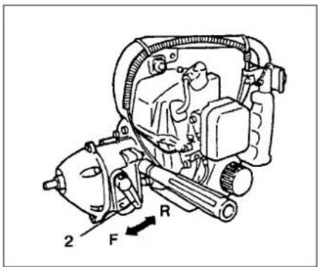
2 F R

Fig. 2-5C
Fig. 2-5D

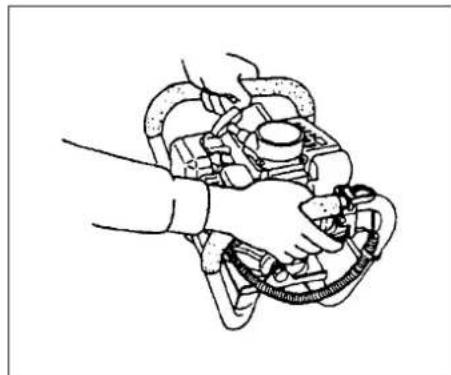
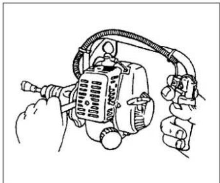
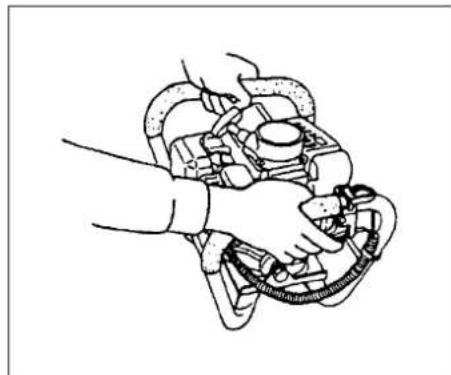
Drilling (Fig. 2-5, 5B)

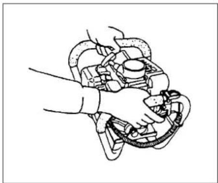
•Always hold unit firmly with both hands on handles and body well balanced.
- Operate at a high engine speed and let drill bit do the work. Do not force bit into hole.
- If material become twisted around drill bit, stop engine, allow unit to cool and remove wire from spark plug before attempting to clear bit.
- Stop engine and inspect unit if abnormal vibration or noise is generated.

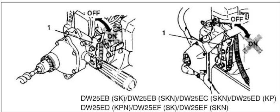
How to operate Lock control (on DW25EB (SK)/DW25EB (SKN)/DW25EC (SKN)/DW25ED (KP)/DW25ED (KPN)/DW25EF (SK)/DW25EF (SKN)) (Fig. 2-5C)

NOTE!

Always stop the engine before operation of lock control.

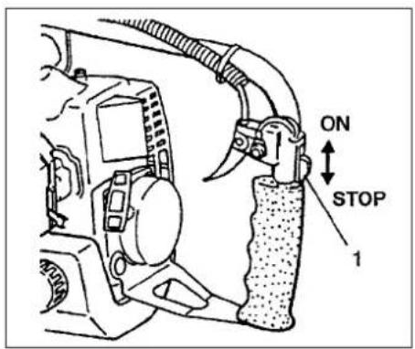
  • When bit has stuck in object, stop engine and turn on lock lever (1).
  • Rotate whole unit counter-clockwise so that the bit can be pulled out easily.
  • If the unit would not move, rotate it clockwise a little and then counterclockwise again.

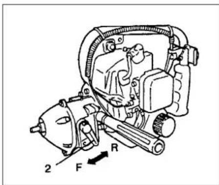
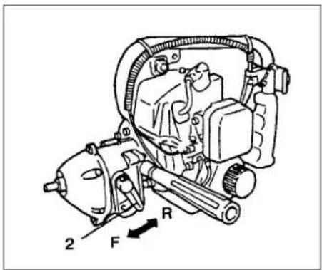
How to operate Reverse control (on DW25EB (SR)/DW25EB (SRN)/DW25EF (SR)/ DW25EF (SRN)) (Fig. 2-5D)

  • Decrease engine speed to idle and move shift lever (2) to R (Reverse) position, then accelerate to pull out.
  • Shift lever may not move unless engine is running. If so, turn drill chuck a little bit by hand.
    * The purpose of Lock control and Reverse control is mainly for easy pullout of bit.
Technical diagram showing mechanical assembly with labeled parts 1, 2, and directional arrows indicating motion or force.

Mechanical assembly diagram showing a tool interacting with a mechanical component (no text or symbols visible)

Technical diagram showing a hand using a wrench to adjust a mechanical component, labeled with number 3

Fig. 2-6 Fig. 2-7 Fig. 2-6B
Illustration of a hand using a tool to lift a mechanical component, no text or symbols present

Technical diagram of a mechanical assembly with labeled parts 1 and 2

ON STOP 1

Fig. 2-7B Fig. 2-8Fig. 2-7C
STOP ON 1 DW25EC (SKN)

1 ON STOP

Fig. 2-8B Fig. 2-8C

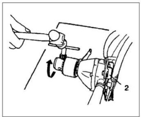
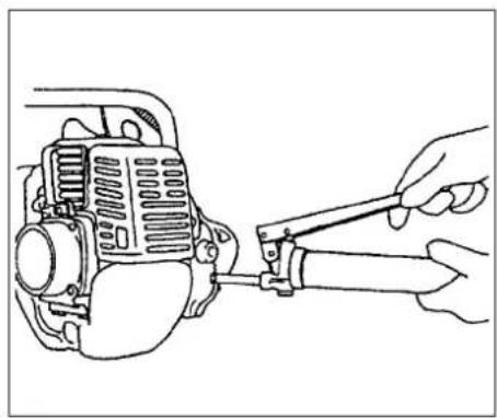
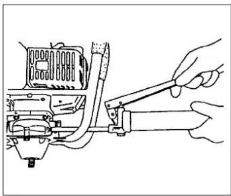
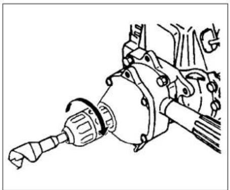
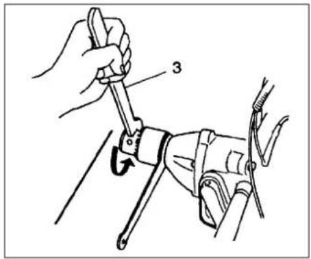
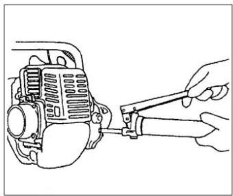
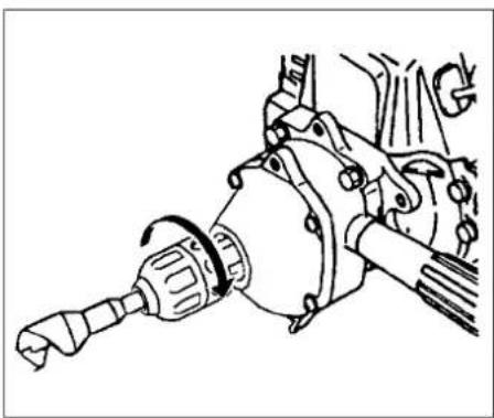
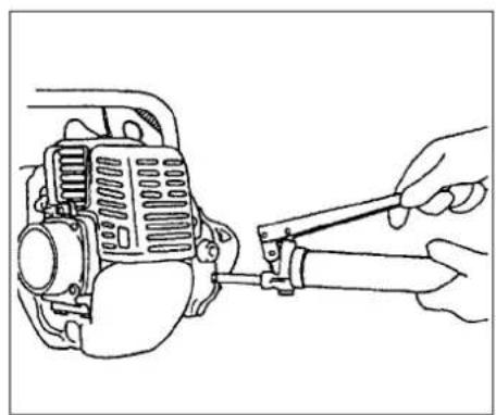
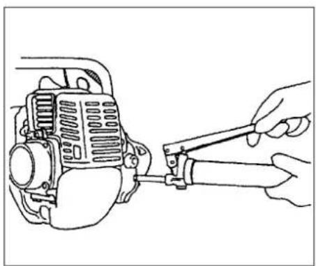
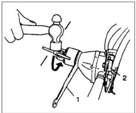
- To tighten the chuck more securely, set a 19mm spanner (1) between gear case and drill chuck to lock drive shaft. Turn on lock lever (2) then hit the mounted chuck handle with a hammer to screw in (clockwise) the chuck. (DW25EB(SK)/DW25EB(SKN)/DW25EC (SKN)/DW25ED(KP)/DW25ED(KPN)/DW 25EF (SK)/DW25EF (SKN)) (Fig. 2-6) - To loosen the chuck, set the spanner on the other side and hit the chuck handle from this side to screw out (counter-clockwise), the chuck with the lock lever on.(DW25EB(SK)/DW25EB(SKN)/DW25 EC (SKN)/DW25ED (KP)/DW25ED (KPN)/DW25EF (SK)/DW25EF (SKN)) (Fig. 2-6B)

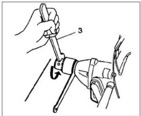
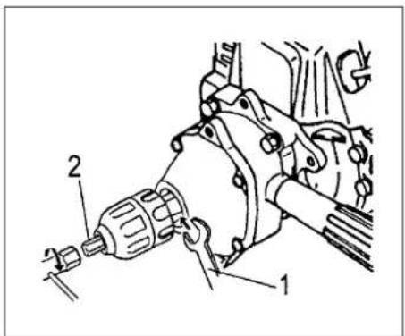
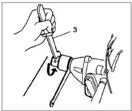
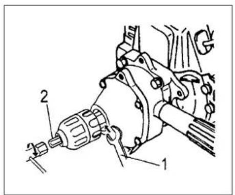
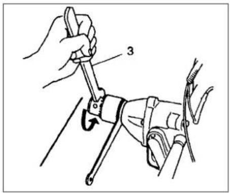
- Note! In case of DW25EB (SR)/DW25EB (SRN)/DW25EF (SR)/DW25EF (SRN), use chuck mount wrench (3) in place of chuck handle and tighten or untighten manually instead of hitting. Do not hit the chuck mount wrench. (Fig. 2-7, 7B) - To install or loosen the keyless chuck, set a 19mm spanner (1) between gear case and chuck to lock drive shaft. Install the locking bar (2) in the tool bag into the chuck, and then tighten(clockwise) the bar (2) with the enclosed box spanner or loosen (counter-clockwise). (Fig.2-7C)

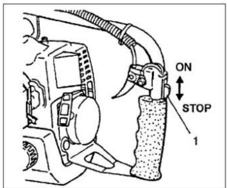
Stopping (Fig. 2-8, 8B, 8C)

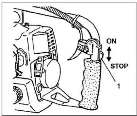
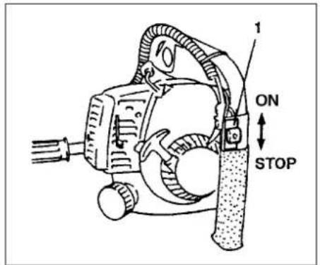
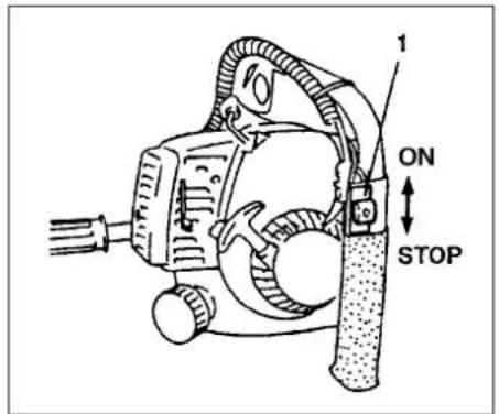
- Decrease engine speed, and push ignition switch to stop position.

Technical diagram showing mechanical assembly with labeled components T and N, including a close-up view of the internal structure.

Fig. 3-1

Exploded view diagram of a mechanical assembly with labeled components and directional arrows indicating assembly steps.

Fig. 3-2

0.6mm (.024°)

Line drawing of a hand using a tool to adjust or install a mechanical component (no text or symbols present)

Line drawing of a hand using a tool to adjust or install a mechanical component (no text or symbols present)

Fig. 3-3 Fig. 3-4 B Fig. 3-4

5. Maintenance

MAINTENANCE. REPLACEMENT, OR REPAIR OF THE EMISSION CONTROL DEVICES AND SYSTEM MAY BE PERFORMED BY ANY NONROAD ENGINE REPAIR ESTABLISHMENT OR INDIVIDUAL.

Carburetor adjustment (Fig. 3-1)

! WARNING!

The bit may be spinning during carburetor adjustments.

! WARNING!

Never start the engine without the complete clutch cover and gear case assembled! Otherwise the clutch can come loose and cause personal injuries.

In the carburetor, fuel is mixed with air. When the engine is test run at the factory, the carburetor is adjusted. A further adjustment may be required, according to climate and altitude. The carburetor has one adjustment possibility: T = Idle speed adjustment screw.

Idle speed adjustment (T)

Check that the air filter is clean. When the idle speed is correct, the bit will not rotate. If adjustment is required, close (clockwise) the T-screw, with the engine running, until the bit starts to rotate. Open (counter-clockwise) the screw until the bit stops. You have reached the correct idle speed when the engine runs smoothly in all positions well below the rpm when the bit starts to rotate.

If the bit still rotates after idle speed adjustment, contact HITACHI dealer.

NOTE!

Some models sold areas with strict exhaust emission regulation do not have high and low speed carburetor adjustments. Such adjustments may allow the engine to be operated outside of their emission compliance limits. For these models, the only carburetor adjustment is idle speed.

For models that equipped with low and high speed adjustments; carburetors are pre set at the factory Minor adjustments may optimize performance based on climate, altitude, etc. Never turn the adjustment screws in increments greater than 90 degrees, as engine damage can result from incorrect adjustment If you are not familiar with type of adjustment-assistance HITACHI dealer.

! WARNING!

When the engine is idling the bit must under no circumstances rotate.

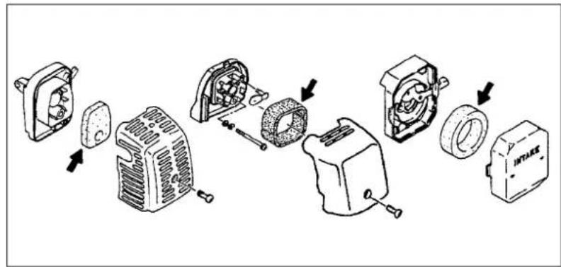
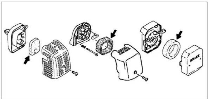
Air filter (Fig. 3-2)

The air filter must be cleaned from dust and dirt in order to avoid:

• Carburetor malfunctions.
- Starting problems.
• Engine power reduction.
- Unnecessary wear on the engine parts.
● Abnormal fuel consumption.

Clean the air filter daily or more often if working in exceptionally dusty areas.

Cleaning the air filter

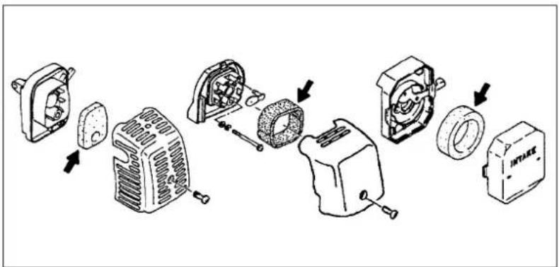
Remove the air filter cover and the filter. Rinse it in warm soap suds. Check that the filter is dry before reassembly. An air filter that has been used for some time cannot be cleaned completely. Therefore, it must regularly be replaced by a new one. A damaged filter must always be replaced.

NOTE!

Saturate the element in 2 cycle oil or the equivalent. Squeeze the element to distribute the oil completely and to remove any excess oil.

Spark plug (Fig. 3-3)

The spark plug condition is influenced by:

• An incorrect carburetor setting.
- Wrong fuel mixture (too much oil in the gasoline)
- A dirty air filter.
- Hard running conditions (such as cold weather).

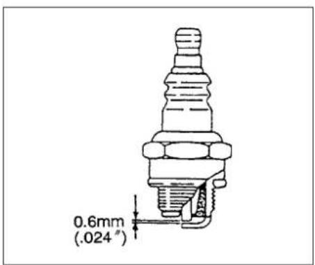
These factors cause deposits on the spark plug electrodes, which may result in malfunction and starting difficulties. If the engine is low on power, difficult to start or runs poorly at idling speed, always check the spark plug first. If the spark plug is dirty, clean it and check the electrode gap. Readjust if necessary. The correct gap is 0.6 mm (.024"). The spark plug should be replaced after about 100 operation hours or earlier if the electrodes are badly eroded.

NOTE!

In some areas, local law requires using a resistor spark plug to suppress ignition signals. If this machine was originally equipped with resistor spark plug, use same type of spark plug for replacement.

Gear case (Fig. 3-4, 4B)

Apply a good quality lithium based grease through the grease fitting. Lubrication should be applied at 50 hour intervals and more frequent at heavy use.

Technical line drawing of a mechanical assembly with two views (top and side), showing internal components and wiring (no text or labels)

Technical line drawings of mechanical components (no text or labels)

Fig. 3-5 Fig. 3-6

Technical line drawings of three mechanical components with exploded views (no text or labels)

Fig. 3-7

Fuel filter (Fig. 3-5)

Remove the fuel filter from the fuel tank and thoroughly wash it in solvent. After that, push the filter into the tank completely.

NOTE!

If the filter is hard due to dust and dirt, replace it.

Cleaning the cylinder fins (Fig. 3-6)

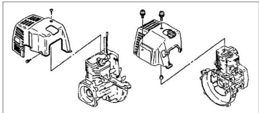
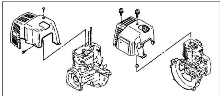
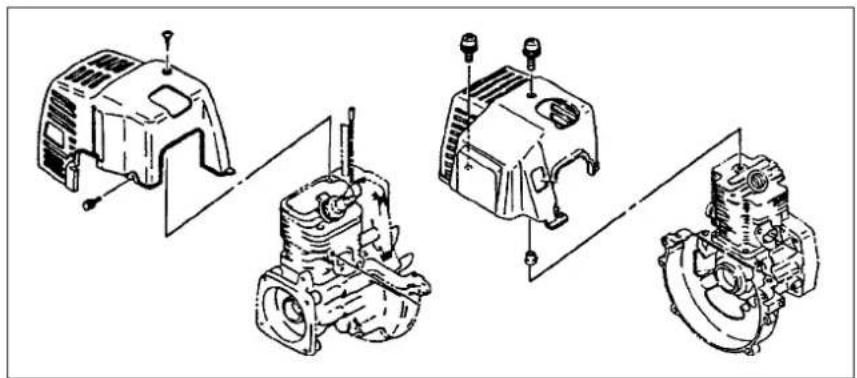
When wood chips are caught between cylinder fins, the engine may overheat, resulting in lower output. To avoid this, always keep cylinder fins and fan case clean.

Every 100 Operating hours, or once a year (more often if conditions require), clean fins and external surfaces of engine of dust, dirt and oil deposits which can contribute to improper cooling.

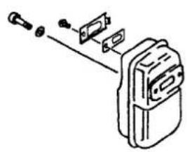
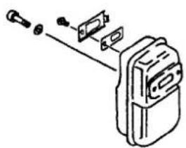
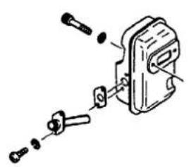
Cleaning the muffler (Fig. 3-7)

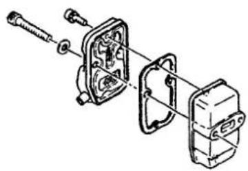
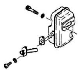
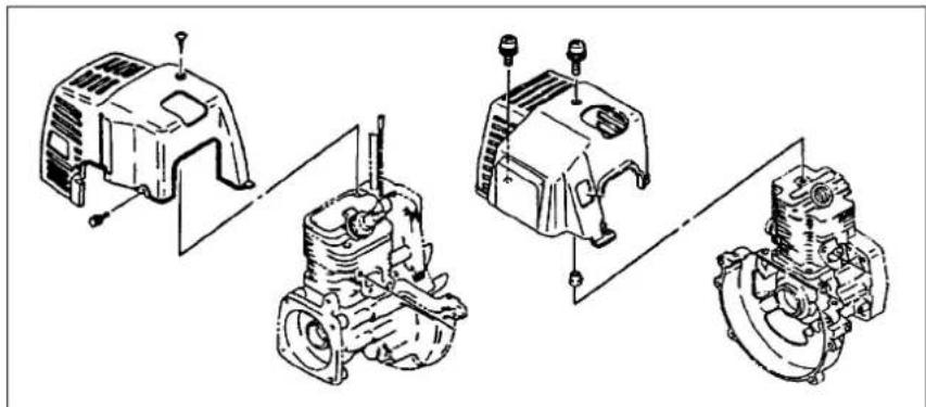
Remove the muffler and spark arrestor (if so equipped), and clean out any excess carbon from the exhaust port or muffler inlet every 100 hours of operation.

For long-term storage

Drain all fuel from the fuel tank. Start and let engine run until it stops. Repair any damage which has resulted from use. Clean the unit with a clean rag, or the use of high pressure air hose. Put a few drops of two-cycle engine oil into the cylinder through the spark plug hole, and spin the engine over several times to distribute oil. Cover the unit and store it in a dry area.

Maintenance schedule

Below you will find some general maintenance instructions. For further information please contact HITACHI dealer.

Daily maintenance

  • Clean the exterior of the unit.
  • Check that the drilling attachment is properly centred, sharp, and without cracks. An offcentred bit induces heavy vibrations that may damage the unit.
  • Chock that the drilling attachment is sufficiently tightened.
  • Check that nuts and screws are sufficiently tightened.

Weekly maintenance

  • Check the starter, especially cord and return spring.
  • Clean the exterior of the spark plug.
  • Remove it and check the electrode gap.
    Adjust it to 0.6 mm, or change the spark plug.
  • Clean the cooling fins on the cylinder and check that the air intake at the starter is not clogged.
  • Check that the angle gear is filled with grease up to 3/4.
  • Clean the air filter.

Monthly maintenance

  • Rinse the fuel tank with gasoline.
  • Clean the exterior of the carburetor and the space around it.
  • Clean the fan and the space around it.

6. Specifications

MODEL DW25EA (SN)/

DW25EA (S)

DW25ED (KP)/

DW25ED (KPN)
HITACHI DW25EF(SRP) - Specifications - 1

Engine Size (ml) 22 (1.34 cu. in.)

24 (1.46 cu. in.)

HITACHI DW25EF(SRP) - Specifications - 2

Spark Plug ...... NGK BPM-6A or BPMR-6A

Champion CJ-8Y or RCJ-8Y

HITACHI DW25EF(SRP) - Specifications - 3

HITACHI DW25EF(SRP) - Specifications - 4

Fuel Tank Capacity (I)....0.35 (11.8 fl. oz)

0.33 (11.2 fl. oz)

HITACHI DW25EF(SRP) - Specifications - 5

Dry Weight (kg) 4.0(8.8 lbs)

4.9(10.8 lbs)

HITACHI DW25EF(SRP) - Specifications - 6

Chuck Capacity (mm).... 12.7(1/2 in)

HITACHI DW25EF(SRP) - Specifications - 7

Drive Shaft Diameter....1/2"-20 UNF

HITACHI DW25EF(SRP) - Specifications - 8

HITACHI DW25EF(SRP) - Specifications - 9

Max. Bit Size (mm)....25.4(1 in) (Wood)

HITACHI DW25EF(SRP) - Specifications - 10

Reverse Control......

Lock Control....

DW25ED (KP)/

DW25ED (KPN) ○

HITACHI DW25EF(SRP) - Specifications - 11

Sound pressure level (dB(A)) .... LpA

(EN 27917) 91.9

99.6

HITACHI DW25EF(SRP) - Specifications - 12

Sound power level (db(A))..... LwA

104

HITACHI DW25EF(SRP) - Specifications - 13

Technical line drawing of a mechanical assembly (no text or symbols visible)

Vibration level (m/s²) (ISO 7916)

Front handle 2.7 7.7

Rear handle 3.9 8.4

NOTE : Equivalent noise level/vibration level are calculated as the time-weighted energy total for noise/vibration levels under various working conditions with the following time distribution : 1/2 idle, 1/2 racing.

*All data subject to change without notice.

MODELDW25EB (SK)/DW25EB (SKN) DW25EB (SR)/DW25EB (SRN)DW25EC (SKN)DW25EF (SK)/DW25EF (SKN) DW25EF (SR)/DW25EF (SRN)
HITACHI DW25EF(SRP) - Specifications - 15
Engine Size (ml)24 (1.46 cu. in.)27 (1.64 cu. in.)
HITACHI DW25EF(SRP) - Specifications - 16
Spark PlugNGK BPM-6A or BPMR-6A Champion CJ-8Y or RCJ-8Y
HITACHI DW25EF(SRP) - Specifications - 17
Fuel Tank Capacity (I)0.35 (11.8 fl. oz)0.67(22.6 fl. oz)
HITACHI DW25EF(SRP) - Specifications - 18
Dry Weight (kg)DW25EB (SK)/DW25EB (SKN) 4.5(9.9 lbs) DW25EB (SR)/DW25EB (SRN) 5.0(11.0 lbs)6.0(13.2 lbs)DW25EF (SK)/DW25EF (SKN) 4.9(10.8 lbs) DW25EF (SR)/DW25EF (SRN) 5.4(11.9 lbs)
HITACHI DW25EF(SRP) - Specifications - 19
Chuck Capacity(mm)12.7(1/2 in)
Drive Shaft Diameter1/2"-20 UNF
HITACHI DW25EF(SRP) - Specifications - 20
Max. Bit Size (mm)25.4(1 in)
(Wood)
Reverse ControlDW25EB (SR)/DW25EB (SRN) ○DW25EF (SR)/DW25EF (SRN) ○
Lock ControlDW25EB (SK)/DW25EB (SKN) ○DW25EF (SK)/DW25EF (SKN) ○
HITACHI DW25EF(SRP) - Specifications - 21
Sound pressure level (dB(A))LpA 94.0 94.191.2
(EN 27917)
HITACHI DW25EF(SRP) - Specifications - 22
Sound power level (db(A))LwA 104 104116
HITACHI DW25EF(SRP) - Specifications - 23
Vibration level (m/s2) (ISO 7916)
Front handle7.81Right 6.50Front handle DW25EF (SK) 6.48
Rear handle5.66Left 6.76Rear handle DW25EF (SKN) 5.71
Front handleDW25EF (SR) 7.05
Rear handleDW25EF (SRN) 7.17

NOTE : Equivalent noise level/vibration level are calculated as the time-weighted energy total for noise/vibration levels under various working conditions with the following time distribution : 1/2 idle, 1/2 racing. *All data subject to change without notice.

HITACHI

DW25EA (SN)/DW25EA (S) DW25EB (SK)/DW25EB (SKN) DW25EB (SR)/DW25EB (SRN) DW25EC (SKN)/DW25ED (KP) DW25ED (KPN)/DW25EF (SK) DW25EF (SKN)/DW25EF (SR) DW25EF (SRN)

Icon of a person reading a book inside a circle (no text or symbols)

Simple line drawing of an open book and a lowercase 'i' symbol, no text or labels present

Simple line icon showing an open book and a lowercase 'i' symbol, no text or labels present.

Do not touch the bit when running the engine.

DW25EA (SN)/DW25EA (S)

DW25EB (SK)/DW25EB (SKN)

DW25EB (SR)/DW25EB (SRN)

DW25EC (SKN)/DW25ED (KP)

DW25ED (KPN)/DW25EF (SK)

DW25EF (SKN)/DW25EF (SR)

DW25EF (SRN)

Technical diagram of a mechanical device with numbered components labeled 11, 13, and 14

Technical line drawing of a mechanical device with hoses and components (no text or symbols)

Line drawing of a mechanical device with hoses and wheels (no text or symbols)

Technical line drawing of a mechanical pump assembly with hoses and housing (no text or labels)

4

Technical line drawing of a mechanical assembly with no visible text or symbols

Fig.1-1 Fig.1-1C Fig.1-1B
Technical line drawing of a mechanical assembly with a tool and housing (no text or symbols)

Fig.1-1D

Line drawing of a fuel can pouring liquid into a container with an icon of fuel (no text or symbols)

Fig.2-1

3. Zusammenbau

STOP ON 1 DW25EC (SKN)

5 4

Fig. 2-2 Fig. 2-2C Fig. 2-2B
Line drawing of a mechanical device with labeled parts (no text or symbols present)

CLOSED RUN 4

CLOSED RUN

Fig. 2-3

Fig. 2-2D Fig. 2-2E
CLOSED key tago RUN

Three technical line drawings of automotive engine components, showing internal assemblies without any text or symbols.

Fig. 2-3B
Fig. 2-4

Anlassen

Illustration of hands holding a mechanical device with hoses and components (no text or symbols)

Fig. 2-5 Fig. 2-5B

1 OFF ON 1 OFF ON DW25EB (SK)/DW25EB (SKN)/DW25EC (SKN)/DW25ED (KP) DW25ED (KPN)/DW25EF (SK)/DW25EF (SKN)

Fig. 2-5C

2 F R

Fig. 2-5D

Mechanical assembly diagram showing a hand operating a tool with a rotating component (no text or symbols)

Technical diagram showing a hand using a wrench to adjust a mechanical component, labeled with number 3

Fig. 2-6 Fig. 2-7 Fig. 2-6B
Illustration of a hand using a tool to lift a cylindrical component, with no visible text or symbols

Technical diagram of a mechanical assembly with labeled parts 1 and 2

ON STOP 1

Fig. 2-7B Fig. 2-8Fig. 2-7C
STOP ON 1 DW25EC (SKN)

1 ON STOP

Fig. 2-8B Fig. 2-8C

Fig. 3-1

Exploded view diagram of a mechanical assembly with labeled components and directional arrows indicating assembly steps.

Fig. 3-2

0.6mm (.024°)

Line drawing of a hand using a tool to adjust or install a mechanical component (no text or symbols present)

Line drawing of a hand using a tool to adjust or install a mechanical component (no text or symbols present)

Fig. 3-3 Fig. 3-4 B Fig. 3-4

5. Wartung

Technical line drawings of mechanical components (no text or labels)

Fig. 3-5 Fig. 3-6

Mechanical assembly diagram showing a bracket with bolts and shafts (no text or labels)

Mechanical assembly diagram showing exploded view of a mechanical component with bolts and housing (no text or labels)

Diagram of a mechanical device with exploded view showing internal components (no text or labels)

Fig. 3-7

DW25EA (SN)/DW25EA (S) DW25EB (SK)/DW25EB (SKN) DW25EB (SR)/DW25EB (SRN) DW25EC (SKN)/DW25ED (KP) DW25ED (KPN)/DW25EF (SK) DW25EF (SKN)/DW25EF (SR) DW25EF (SRN)
Icon of a person reading a book inside a circle (no text or symbols)

Simple line drawing of an open book and a lowercase 'i' symbol, no text or labels present

Simple line icon showing an open book and a lowercase 'i' symbol, no text or labels present

HITACHI DW25EF(SRP) - Wartung - 8

HITACHI DW25EF(SRP) - Wartung - 9

HITACHI DW25EF(SRP) - Wartung - 10

HITACHI DW25EF(SRP) - Wartung - 11

HITACHI DW25EF(SRP) - Wartung - 12

HITACHI DW25EF(SRP) - Wartung - 13

HITACHI DW25EF(SRP) - Wartung - 14

HITACHI DW25EF(SRP) - Wartung - 15

HITACHI DW25EF(SRP) - Wartung - 16

HITACHI DW25EF(SRP) - Wartung - 17

HITACHI DW25EF(SRP) - Wartung - 18

HITACHI DW25EF(SRP) - Wartung - 19

HITACHI DW25EF(SRP) - Wartung - 20

HITACHI DW25EF(SRP) - Wartung - 21

HITACHI DW25EF(SRP) - Wartung - 22

HITACHI DW25EF(SRP) - Wartung - 23

HITACHI DW25EF(SRP) - Wartung - 24

HITACHI DW25EF(SRP) - Wartung - 25

HITACHI DW25EF(SRP) - Wartung - 26

HITACHI DW25EF(SRP) - Wartung - 27

HITACHI DW25EF(SRP) - Wartung - 28

HITACHI DW25EF(SRP) - Wartung - 29

HITACHI DW25EF(SRP) - Wartung - 30

HITACHI DW25EF(SRP) - Wartung - 31

HITACHI DW25EF(SRP) - Wartung - 32

HITACHI DW25EF(SRP) - Wartung - 33

HITACHI DW25EF(SRP) - Wartung - 34

HITACHI DW25EF(SRP) - Wartung - 35

HITACHI DW25EF(SRP) - Wartung - 36

HITACHI DW25EF(SRP) - Wartung - 37

HITACHI DW25EF(SRP) - Wartung - 38

HITACHI DW25EF(SRP) - Wartung - 39

HITACHI DW25EF(SRP) - Wartung - 40

HITACHI DW25EF(SRP) - Wartung - 41

HITACHI DW25EF(SRP) - Wartung - 42

HITACHI DW25EF(SRP) - Wartung - 43

HITACHI DW25EF(SRP) - Wartung - 44

HITACHI DW25EF(SRP) - Wartung - 45

HITACHI DW25EF(SRP) - Wartung - 46

HITACHI DW25EF(SRP) - Wartung - 47

HITACHI DW25EF(SRP) - Wartung - 48

HITACHI DW25EF(SRP) - Wartung - 49

HITACHI DW25EF(SRP) - Wartung - 50

HITACHI DW25EF(SRP) - Wartung - 51

HITACHI DW25EF(SRP) - Wartung - 52

HITACHI DW25EF(SRP) - Wartung - 53

HITACHI DW25EF(SRP) - Wartung - 54

HITACHI DW25EF(SRP) - Wartung - 55

HITACHI DW25EF(SRP) - Wartung - 56

HITACHI DW25EF(SRP) - Wartung - 57

HITACHI DW25EF(SRP) - Wartung - 58

HITACHI DW25EF(SRP) - Wartung - 59

HITACHI DW25EF(SRP) - Wartung - 60

HITACHI DW25EF(SRP) - Wartung - 61

HITACHI DW25EF(SRP) - Wartung - 62

HITACHI DW25EF(SRP) - Wartung - 63

HITACHI DW25EF(SRP) - Wartung - 64

HITACHI DW25EF(SRP) - Wartung - 65

HITACHI DW25EF(SRP) - Wartung - 66

HITACHI DW25EF(SRP) - Wartung - 67

HITACHI DW25EF(SRP) - Wartung - 68

HITACHI DW25EF(SRP) - Wartung - 69

HITACHI DW25EF(SRP) - Wartung - 70

HITACHI DW25EF(SRP) - Wartung - 71

HITACHI DW25EF(SRP) - Wartung - 72

HITACHI DW25EF(SRP) - Wartung - 73

HITACHI DW25EF(SRP) - Wartung - 74

HITACHI DW25EF(SRP) - Wartung - 75

HITACHI DW25EF(SRP) - Wartung - 76

HITACHI DW25EF(SRP) - Wartung - 77

HITACHI DW25EF(SRP) - Wartung - 78

HITACHI DW25EF(SRP) - Wartung - 79

HITACHI DW25EF(SRP) - Wartung - 80

HITACHI DW25EF(SRP) - Wartung - 81

HITACHI DW25EF(SRP) - Wartung - 82

HITACHI DW25EF(SRP) - Wartung - 83

HITACHI DW25EF(SRP) - Wartung - 84

HITACHI DW25EF(SRP) - Wartung - 85

HITACHI DW25EF(SRP) - Wartung - 86

HITACHI DW25EF(SRP) - Wartung - 87

HITACHI DW25EF(SRP) - Wartung - 88

HITACHI DW25EF(SRP) - Wartung - 89

HITACHI DW25EF(SRP) - Wartung - 90

HITACHI DW25EF(SRP) - Wartung - 91

HITACHI DW25EF(SRP) - Wartung - 92

HITACHI DW25EF(SRP) - Wartung - 93

HITACHI DW25EF(SRP) - Wartung - 94

HITACHI DW25EF(SRP) - Wartung - 95

HITACHI DW25EF(SRP) - Wartung - 96

HITACHI DW25EF(SRP) - Wartung - 97

HITACHI DW25EF(SRP) - Wartung - 98

HITACHI DW25EF(SRP) - Wartung - 99

HITACHI DW25EF(SRP) - Wartung - 100

HITACHI DW25EF(SRP) - Wartung - 101

HITACHI DW25EF(SRP) - Wartung - 102

HITACHI DW25EF(SRP) - Wartung - 103

HITACHI DW25EF(SRP) - Wartung - 104

HITACHI DW25EF(SRP) - Wartung - 105

HITACHI DW25EF(SRP) - Wartung - 106

HITACHI DW25EF(SRP) - Wartung - 107

HITACHI DW25EF(SRP) - Wartung - 108

HITACHI DW25EF(SRP) - Wartung - 109

HITACHI DW25EF(SRP) - Wartung - 110

HITACHI DW25EF(SRP) - Wartung - 111

HITACHI DW25EF(SRP) - Wartung - 112

HITACHI DW25EF(SRP) - Wartung - 113

HITACHI DW25EF(SRP) - Wartung - 114

HITACHI DW25EF(SRP) - Wartung - 115

HITACHI DW25EF(SRP) - Wartung - 116

HITACHI DW25EF(SRP) - Wartung - 117

HITACHI DW25EF(SRP) - Wartung - 118

HITACHI DW25EF(SRP) - Wartung - 119

HITACHI DW25EF(SRP) - Wartung - 120

HITACHI DW25EF(SRP) - Wartung - 121

HITACHI DW25EF(SRP) - Wartung - 122

HITACHI DW25EF(SRP) - Wartung - 123

HITACHI DW25EF(SRP) - Wartung - 124

HITACHI DW25EF(SRP) - Wartung - 125

HITACHI DW25EF(SRP) - Wartung - 126

HITACHI DW25EF(SRP) - Wartung - 127

HITACHI DW25EF(SRP) - Wartung - 128

HITACHI DW25EF(SRP) - Wartung - 129

HITACHI DW25EF(SRP) - Wartung - 130

HITACHI DW25EF(SRP) - Wartung - 131

HITACHI DW25EF(SRP) - Wartung - 132

HITACHI DW25EF(SRP) - Wartung - 133

HITACHI DW25EF(SRP) - Wartung - 134

HITACHI DW25EF(SRP) - Wartung - 135

HITACHI DW25EF(SRP) - Wartung - 136

HITACHI DW25EF(SRP) - Wartung - 137

HITACHI DW25EF(SRP) - Wartung - 138

HITACHI DW25EF(SRP) - Wartung - 139

HITACHI DW25EF(SRP) - Wartung - 140

HITACHI DW25EF(SRP) - Wartung - 141

HITACHI DW25EF(SRP) - Wartung - 142

HITACHI DW25EF(SRP) - Wartung - 143

HITACHI DW25EF(SRP) - Wartung - 144

HITACHI DW25EF(SRP) - Wartung - 145

HITACHI DW25EF(SRP) - Wartung - 146

HITACHI DW25EF(SRP) - Wartung - 147

HITACHI DW25EF(SRP) - Wartung - 148

HITACHI DW25EF(SRP) - Wartung - 149

HITACHI DW25EF(SRP) - Wartung - 150

HITACHI DW25EF(SRP) - Wartung - 151

HITACHI DW25EF(SRP) - Wartung - 152

HITACHI DW25EF(SRP) - Wartung - 153

HITACHI DW25EF(SRP) - Wartung - 154

HITACHI DW25EF(SRP) - Wartung - 155

HITACHI DW25EF(SRP) - Wartung - 156

HITACHI DW25EF(SRP) - Wartung - 157

HITACHI DW25EF(SRP) - Wartung - 158

HITACHI DW25EF(SRP) - Wartung - 159

HITACHI DW25EF(SRP) - Wartung - 160

HITACHI DW25EF(SRP) - Wartung - 161

HITACHI DW25EF(SRP) - Wartung - 162

HITACHI DW25EF(SRP) - Wartung - 163

HITACHI DW25EF(SRP) - Wartung - 164

HITACHI DW25EF(SRP) - Wartung - 165

HITACHI DW25EF(SRP) - Wartung - 166

HITACHI DW25EF(SRP) - Wartung - 167

HITACHI DW25EF(SRP) - Wartung - 168

HITACHI DW25EF(SRP) - Wartung - 169

HITACHI DW25EF(SRP) - Wartung - 170

HITACHI DW25EF(SRP) - Wartung - 171

HITACHI DW25EF(SRP) - Wartung - 172

HITACHI DW25EF(SRP) - Wartung - 173

HITACHI DW25EF(SRP) - Wartung - 174

HITACHI DW25EF(SRP) - Wartung - 175

HITACHI DW25EF(SRP) - Wartung - 176

HITACHI DW25EF(SRP) - Wartung - 177

HITACHI DW25EF(SRP) - Wartung - 178

HITACHI DW25EF(SRP) - Wartung - 179

HITACHI DW25EF(SRP) - Wartung - 180

HITACHI DW25EF(SRP) - Wartung - 181

HITACHI DW25EF(SRP) - Wartung - 182

HITACHI DW25EF(SRP) - Wartung - 183

HITACHI DW25EF(SRP) - Wartung - 184

HITACHI DW25EF(SRP) - Wartung - 185

HITACHI DW25EF(SRP) - Wartung - 186

HITACHI DW25EF(SRP) - Wartung - 187

HITACHI DW25EF(SRP) - Wartung - 188

HITACHI DW25EF(SRP) - Wartung - 189

HITACHI DW25EF(SRP) - Wartung - 190

HITACHI DW25EF(SRP) - Wartung - 191

HITACHI DW25EF(SRP) - Wartung - 192

HITACHI DW25EF(SRP) - Wartung - 193

HITACHI DW25EF(SRP) - Wartung - 194

HITACHI DW25EF(SRP) - Wartung - 195

HITACHI DW25EF(SRP) - Wartung - 196

HITACHI DW25EF(SRP) - Wartung - 197

HITACHI DW25EF(SRP) - Wartung - 198

HITACHI DW25EF(SRP) - Wartung - 199

HITACHI DW25EF(SRP) - Wartung - 200

HITACHI DW25EF(SRP) - Wartung - 201

HITACHI DW25EF(SRP) - Wartung - 202

HITACHI DW25EF(SRP) - Wartung - 203

HITACHI DW25EF(SRP) - Wartung - 204

HITACHI DW25EF(SRP) - Wartung - 205

HITACHI DW25EF(SRP) - Wartung - 206

HITACHI DW25EF(SRP) - Wartung - 207

HITACHI DW25EF(SRP) - Wartung - 208

HITACHI DW25EF(SRP) - Wartung - 209

HITACHI DW25EF(SRP) - Wartung - 210

HITACHI DW25EF(SRP) - Wartung - 211

HITACHI DW25EF(SRP) - Wartung - 212

HITACHI DW25EF(SRP) - Wartung - 213

HITACHI DW25EF(SRP) - Wartung - 214

HITACHI DW25EF(SRP) - Wartung - 215

HITACHI DW25EF(SRP) - Wartung - 216

HITACHI DW25EF(SRP) - Wartung - 217

HITACHI DW25EF(SRP) - Wartung - 218

HITACHI DW25EF(SRP) - Wartung - 219

HITACHI DW25EF(SRP) - Wartung - 220

HITACHI DW25EF(SRP) - Wartung - 221

HITACHI DW25EF(SRP) - Wartung - 222

HITACHI DW25EF(SRP) - Wartung - 223

HITACHI DW25EF(SRP) - Wartung - 224

HITACHI DW25EF(SRP) - Wartung - 225

HITACHI DW25EF(SRP) - Wartung - 226

HITACHI DW25EF(SRP) - Wartung - 227

HITACHI DW25EF(SRP) - Wartung - 228

HITACHI DW25EF(SRP) - Wartung - 229

HITACHI DW25EF(SRP) - Wartung - 230

HITACHI DW25EF(SRP) - Wartung - 231

HITACHI DW25EF(SRP) - Wartung - 232

HITACHI DW25EF(SRP) - Wartung - 233

HITACHI DW25EF(SRP) - Wartung - 234

HITACHI DW25EF(SRP) - Wartung - 235

HITACHI DW25EF(SRP) - Wartung - 236

HITACHI DW25EF(SRP) - Wartung - 237

HITACHI DW25EF(SRP) - Wartung - 238

HITACHI DW25EF(SRP) - Wartung - 239

HITACHI DW25EF(SRP) - Wartung - 240

HITACHI DW25EF(SRP) - Wartung - 241

HITACHI DW25EF(SRP) - Wartung - 242

HITACHI DW25EF(SRP) - Wartung - 243

HITACHI DW25EF(SRP) - Wartung - 244

HITACHI DW25EF(SRP) - Wartung - 245

HITACHI DW25EF(SRP) - Wartung - 246

HITACHI DW25EF(SRP) - Wartung - 247

HITACHI DW25EF(SRP) - Wartung - 248

HITACHI DW25EF(SRP) - Wartung - 249

HITACHI DW25EF(SRP) - Wartung - 250

HITACHI DW25EF(SRP) - Wartung - 251

HITACHI DW25EF(SRP) - Wartung - 252

HITACHI DW25EF(SRP) - Wartung - 253

HITACHI DW25EF(SRP) - Wartung - 254

HITACHI DW25EF(SRP) - Wartung - 255

HITACHI DW25EF(SRP) - Wartung - 256

HITACHI DW25EF(SRP) - Wartung - 257

HITACHI DW25EF(SRP) - Wartung - 258

HITACHI DW25EF(SRP) - Wartung - 259

HITACHI DW25EF(SRP) - Wartung - 260

HITACHI DW25EF(SRP) - Wartung - 261

HITACHI DW25EF(SRP) - Wartung - 262

Δηλωση συμβατοτητας

H Nikko Tanaka Engineering Co., Ltd., 3-4-29 Tsudanuma, Narashino, Chiba, Japan

DW25EA (SN)/DW25EA (S)

DW25EB (SK)/DW25EB (SKN)

DW25EB (SR)/DW25EB (SRN)

DW25EC (SKN)/DW25ED (KP)

DW25ED (KPN)/DW25EF (SK)

DW25EF (SKN)/DW25EF (SR)

DW25EF (SRN)
Technical diagram of a mechanical device with numbered components labeled 11, 13, and 14

Technical line drawing of a mechanical device with hoses and components (no text or symbols)

Line drawing of a mechanical device with hoses and control knobs (no text or symbols)

Technical line drawing of a mechanical pump assembly (no text or labels)

Eik.1-1

4

Eik.1-1CEik.1-1B

Technical line drawing of a mechanical assembly with no visible text or symbols

Technical line drawing of a mechanical assembly with a tool and housing (no text or symbols)

Elk.1-1D

Line drawing of a fuel can pouring liquid into a container with an icon of fuel (no text or symbols)

Eik.2-1

Elk. 2-2

STOP ON 1 DW25EC (SKN)

Eik. 2-2CEik. 2-2B

5 4

Technical diagram showing labeled mechanical components with numbered parts 4 and 5

Line drawing of a mechanical device with labeled parts (no text or symbols present)

Eik. 2-2D

CLOSED RUN 4

Eik. 2-2E

CLOSED RUN

Eik. 2-3

CLOSED RUN

Eik. 2-3B

Three technical line drawings of mechanical components, showing engine, motor, and fan assembly (no text or labels)

Fig. 2-4

Εκκίνηση

Eik. 2-5 Eik. 2-5B

Illustration of hands holding a mechanical device with hoses and components (no text or symbols)

2 F R

Elk. 2-5D

Elk. 2-5C
1 OFF ON 1 OFF ON DW25EB (SK)/DW25EB (SKN)/DW25EC (SKN)/DW25ED (KP) DW25ED (KPN)/DW25EF (SK)/DW25EF (SKN)

(SKN)/DW25ED (KP)/DW25ED (KPN)/

DW25EF (SK)/DW25EF (SKN)) (Eik. 2-5C)

ΣΗΜΕΙΩΣΗ!

Elk. 2-6

Mechanical assembly diagram showing a hand operating a tool with a rotating component (no text or symbols)

Eik. 2-6B

Technical diagram showing a hand using a wrench to adjust a mechanical component with labeled parts 3 and an arrow indicating rotation.

Elk. 2-7

Illustration of a hand using a tool to lift a mechanical component, no text or symbols present

Eik. 2-7B

Technical diagram of a mechanical assembly with labeled parts 1 and 2

Eik. 2-8Eik. 2-7C

ON STOP 1

STOP ON 1 DW25EC (SKN)

Eik. 2-8B

1 ON STOP

Eik. 2-8C

Eik. 3-1

Exploded view diagram of a mechanical assembly with labeled components and directional arrows indicating assembly steps.

Eik. 3-2

0.6mm (.024°)

Elk. 3-3

Line drawing of a hand using a tool to adjust or install a motor component (no text or symbols present)

Eik. 3-4BEik. 3-4

Line drawing of a hand using a tool to adjust or install a mechanical component (no text or symbols present)

5. Συντήρηση

Eik. 3-5

Technical line drawings of mechanical components (no text or labels)

Eik. 3-6

Technical line drawings of three mechanical components with exploded views (no text or labels)

Eik. 3-7

DW25EA (SN)/ DW25EA (S)

DW25ED (KP)/ DW25ED (KPN)

HITACHI DW25EF(SRP) - Συντήρηση - 3

DW25ED (KP)/ DW25ED (KPN) ○

HITACHI DW25EF(SRP) - Συντήρηση - 4

DW25EA (SN)/DW25EA (S) DW25EB (SK)/DW25EB (SKN) DW25EB (SR)/DW25EB (SRN) DW25EC (SKN)/DW25ED (KP) DW25ED (KPN)/DW25EF (SK) DW25EF (SKN)/DW25EF (SR) DW25EF (SRN)
Icon of a person reading a book inside a circle (no text or symbols)

Simple line drawing of an open book and a lowercase 'i' symbol, no text or labels present

Do not touch the bit when running the engine.

DW25EA (SN)/DW25EA (S)

DW25EB (SK)/DW25EB (SKN)

DW25EB (SR)/DW25EB (SRN)

DW25EC (SKN)/DW25ED (KP)

DW25ED (KPN)/DW25EF (SK)

DW25EF (SKN)/DW25EF (SR)

DW25EF (SRN)

Technical diagram of a mechanical device with numbered components labeled 11, 13, and 14

Technical line drawing of a mechanical device with hoses and components (no text or symbols)

Line drawing of a mechanical device with hoses and control knobs (no text or symbols)

Technical line drawing of a mechanical pump assembly (no text or labels)

Rys. 1-1

4

Rys. 1-1B Rys. 1-1C

Technical line drawing of a mechanical assembly with no visible text or symbols

Technical line drawing of a mechanical assembly with a tool and housing (no text or symbols)

Rys. 1-1D

Illustration of a fuel can pouring liquid into a container with an electric pump icon (no text or symbols)

Rys. 2-1

Rys. 2-2

STOP ON 1 DW25EC (SKN)

Rys. 2-2B Rys. 2-2C

Technical diagram of a mechanical assembly with numbered components labeled 4 and 5

Technical diagram of a mechanical assembly with numbered components labeled 4 and 5

Technical diagram of a vehicle's front-mounted device with labeled parts 4 and 5

Rys. 2-2D

CLOSED RUN 4

Rys. 2-2E Rys. 2-3

CLOSED RUN

CLOSED RUN

CLOSED NO TACO RUN

Rys. 2-3B

Three technical line drawings of automotive engine components, showing internal components and assembly (no text or labels)

Rys. 2-4

Uruchomienie

Line drawing of hands holding a mechanical component (no text or symbols)

Rys. 2-5 Rys. 2-5B

1 OFF ON 1 OFF ON DW25EB (SK)/DW25EB (SKN)/DW25EC (SKN)/DW25ED (KP) DW25ED (KPN)/DW25EF (SK)/DW25EF (SKN)

2 F R

Rys. 2-5C Rys. 2-5D

Wiercenie (Rys. 2-5B)

Rys. 2-6

Mechanical assembly diagram showing a hand operating a tool with a rotating component (no text or symbols)

Rys. 2-6B Rys. 2-7

Technical diagram showing a hand using a wrench to adjust a mechanical component, labeled with number 3

ON STOP 1

Line drawing of a hand using a tool to lift a mechanical component (no text or symbols)

Rys. 2-7B

Technical diagram of a mechanical assembly with labeled parts 1 and 2

Rys. 2-7C Rys. 2-8

STOP ON 1 DW25EC (SKN)

Rys. 2-8B

1 ON STOP

Rys. 2-8C

Exploded view diagram of automotive engine components with labeled parts and directional arrows indicating assembly or repair.

Rys. 3-1 Rys. 3-2

0.6mm (.024")

Rys. 3-3 Rys. 3-4 Rys. 3-4B
Line drawing of a hand using a tool to adjust or install a mechanical component (no text or symbols present)

Line drawing of a hand using a tool to adjust or install a mechanical component (no text or symbols present)

5. Konserwacja

KONSERWACJE, WYMIANĘ LUB NAPRAWĘ URZĄDZEŃ. I SYSTEMU KONTROLI EMISJI MOŻE WYKONAĆ ZAKŁAD NAPRAWY SILNIKÓW NIEDROGOWYCH LUB OSOBA INDYWIDUALNA.

Technical line drawings of mechanical components (no text or symbols)

Rys. 3-5 Rys. 3-6

Mechanical assembly diagram showing a lever mechanism with no text or symbols

Mechanical assembly diagram showing exploded view of a mechanical component with screws and housing (no text or labels)

Diagram of a mechanical device with exploded view showing components (no text or labels)

Rys. 3-7

Filtr paliwa (Rys. 3-5)

DW25EA (SN)/ DW25EA (S)

DW25ED (KP)/ DW25ED (KPN)

HITACHI DW25EF(SRP) - Filtr paliwa (Rys. 3-5) - 1

Cieżar na sucho (kg).... 4.0(8.8 lbs) 4.9(10.8 lbs)

HITACHI DW25EF(SRP) - Filtr paliwa (Rys. 3-5) - 2

DW25ED (KP)/ DW25ED (KPN) ○

HITACHI DW25EF(SRP) - Filtr paliwa (Rys. 3-5) - 3

DW25EA (SN)/DW25EA (S) DW25EB (SK)/DW25EB (SKN) DW25EB (SR)/DW25EB (SRN) DW25EC (SKN)/DW25ED (KP) DW25ED (KPN)/DW25EF (SK) DW25EF (SKN)/DW25EF (SR) DW25EF (SRN)
Icon of a person reading a book inside a circle (no text or symbols)

Simple line drawing of an open book and a lowercase 'i' symbol (no text or labels)

Icon showing a lowercase 'i' next to an open book, symbolizing information (no text or symbols present)

Do not touch the bit when running the engine.

Mi, a Nikko Tanaka Engineering Co., Ltd., 3-4-29 Tsudanuma, Narashino, Chiba, Japan

DW25EA (SN)/DW25EA (S)

DW25EB (SK)/DW25EB (SKN)

DW25EB (SR)/DW25EB (SRN)

DW25EC (SKN)/DW25ED (KP)

DW25ED (KPN)/DW25EF (SK)

DW25EF (SKN)/DW25EF (SR)

DW25EF (SRN)

Technical diagram of a mechanical device with numbered components labeled 11, 13, and 14

Technical line drawing of a mechanical device with hoses and components (no text or symbols)

Line drawing of a mechanical device with hoses and control knobs (no text or symbols)

Technical line drawing of a mechanical pump assembly (no text or labels)

1-1. ábra

4

1-1B. ábra 1-1C. ábra

Technical line drawing of a mechanical assembly with no visible text or symbols

Technical line drawing of a mechanical assembly with a tool and housing (no text or symbols)

1-1D. ábra

Illustration of a fuel can pouring liquid into a container with an electric pump icon (no text or symbols)

2-1. ábra

3. Összeszerelés

2-2. ábra

STOP ON 1 DW25EC (SKN)

2-2B. ábra 2-2C. ábra

5 4

Technical diagram of a mechanical assembly with numbered components labeled 4 and 5

Technical diagram of a vehicle battery with labeled parts, showing internal components and wiring connections.

2-2D. ábra

CLOSED RUN 4

2-2E. ábra 2-3. ábra

CLOSED RUN

CLOSED RUN

CLOSED NO TACU RUN

2-3B. ábra

Three technical line drawings of automotive engine components, showing internal assemblies without any text or symbols.

2-4. ábra

Indítás

2-5. ábra 2-5B. ábra

Line drawing of hands holding a mechanical component (no text or symbols)

2 F R

Fúrás (2-5B. ábra)

2-6. ábra

Mechanical assembly diagram showing a hand operating a tool with a rotating component (no text or symbols)

2-6B. ábra 2-7. ábra

Technical diagram showing a hand using a wrench to adjust a mechanical component, labeled with number 3

ON STOP 1

Line drawing of a hand using a tool to lift a mechanical component (no text or symbols)

2-7B. ábra

Technical diagram of a mechanical assembly with labeled parts 1 and 2

2-8B. ábra

1 ON STOP

2-8C. ábra

Exploded view diagram of automotive engine components with labeled parts and directional arrows indicating assembly or repair.

3-1. ábra 3-2. ábra

0.6mm (.024")

3-3. ábra

Line drawing of a hand using a tool to adjust or install a mechanical component (no text or symbols present)

5. Karbantartás

A MOTOR JAVÍTÁSÁT, KARBANTARTÁSÁT VAGY CSEREJET BÁRMELYIK, NEM AUTÓMOTOROK JAVÍTÁSÁVAL FOGLALKOZÓ SZERVIZ VAGY SZERELŐ ELVÉGEZHETI.

Technical line drawings of mechanical components (no text or symbols)

3-5. ábra 3-6. ábra

Mechanical assembly diagram showing a lever mechanism with no text or symbols

Mechanical assembly diagram showing exploded view of a mechanical component with bolts and housing (no text or labels)

Diagram of a mechanical device with exploded view showing components (no text or labels)

3-7. ábra

DW25EA (SN)/DW25EA (S) DW25EB (SK)/DW25EB (SKN) DW25EB (SR)/DW25EB (SRN) DW25EC (SKN)/DW25ED (KP) DW25ED (KPN)/DW25EF (SK) DW25EF (SKN)/DW25EF (SR) DW25EF (SRN)


Two black-and-white icons: a person reading a book inside a circle and an open book with an open mouth, both without any text or symbols.

Icon showing a lowercase 'i' next to an open book, symbolizing information (no text or symbols present)

Do not touch the bit when running the engine.

My, Nikko Tanaka Engineering Co., Ltd., 3-4-29 Tsudanuma, Narashino, Chiba, Japonsko,

DW25EA (SN)/DW25EA (S)

DW25EB (SK)/DW25EB (SKN)

DW25EB (SR)/DW25EB (SRN)

DW25EC (SKN)/DW25ED (KP)

DW25ED (KPN)/DW25EF (SK)

DW25EF (SKN)/DW25EF (SR)

DW25EF (SRN)

Technical diagram of a mechanical device with numbered components labeled 11, 13, and 14

Technical line drawing of a mechanical device with hoses and components (no text or symbols)

Line drawing of a mechanical device with hoses and control knobs (no text or symbols)

Technical line drawing of a mechanical pump assembly (no text or labels)

Obr. 1-1

4

Obr. 1-1B Obr. 1-1C

Technical line drawing of a mechanical assembly with no visible text or symbols

Technical line drawing of a mechanical assembly with a tool and housing (no text or symbols)

Obr. 1-1D

Illustration of a fuel can pouring liquid into a container with an electric pump icon (no text or symbols)

Obr. 2-1

3. Montáž

Montáž (Obr. 1-1, 1B, 1C)

Obr. 2-2

STOP ON 1 DW25EC (SKN)

Obr. 2-2B Obr. 2-2C

Technical diagram of a mechanical assembly with numbered components labeled 4 and 5

Technical diagram of a mechanical assembly with numbered components labeled 4 and 5

Technical diagram of a vehicle or engine component with labeled parts, including a numbered part '4'

Obr. 2-2D

CLOSED RUN 4

Obr. 2-2E Obr. 2-3

CLOSED RUN

CLOSED RUN

CLOSED NO TACU RUN

Obr. 2-3B

Three technical line drawings of automotive engine components, showing internal assemblies without any text or symbols.

Obr. 2-4

HITACHI DW25EF(SRP) - Montáž (Obr. 1-1, 1B, 1C) - 10

Spouštění

Obr. 2-5

Line drawing of hands holding a mechanical component (no text or symbols)

Obr. 2-5B

1 OFF ON 1 OFF ON DW25EB (SK)/DW25EB (SKN)/DW25EC (SKN)/DW25ED (KP) DW25ED (KPN)/DW25EF (SK)/DW25EF (SKN)

Obr. 2-5C

2 F R

Obr. 2-5D

Obr. 2-6

Mechanical assembly diagram showing a hand operating a tool with a rotating component (no text or symbols)

Obr. 2-6B Obr. 2-7

Technical diagram showing a hand using a wrench to adjust a mechanical component, labeled with number 3.

ON STOP 1

Line drawing of a hand using a tool to lift a mechanical component (no text or symbols)

Obr. 2-7B

Technical diagram of a mechanical assembly with labeled parts 1 and 2

Obr. 2-7C Obr. 2-8

STOP ON 1 DW25EC (SKN)

Obr. 2-8B

1 ON STOP

Obr. 2-8C

Exploded view diagram of automotive engine components with labeled parts and directional arrows indicating assembly or repair.

Obr. 3-1 Obr. 3-2

0.6mm (.024")

Obr. 3-3

Line drawing of a hand using a tool to adjust or install a mechanical component (no text or symbols present)

Obr. 3-4 Obr. 3-4B

Line drawing of a hand using a tool to adjust or install a mechanical component (no text or symbols visible)

POZNÁMKA!

Technical line drawings of mechanical components (no text or symbols)

Obr. 3-5 Obr. 3-6

Mechanical assembly diagram showing a lever mechanism with no text or symbols

Mechanical assembly diagram showing exploded view of a mechanical component with bolts and housing (no text or labels)

Diagram of a mechanical device with exploded view showing components (no text or labels)

Obr. 3-7

DW25EA (SN)/ DW25EA (S)

DW25ED (KP)/ DW25ED (KPN)

HITACHI DW25EF(SRP) - POZNÁMKA! - 5

Objem motoru (ml) 22 (1.34 cu. in.)

24 (1.46 cu. in.)

HITACHI DW25EF(SRP) - POZNÁMKA! - 6

Hrubá váha (kg).... 4.0(8.8 lbs) 4.9(10.8 lbs)

HITACHI DW25EF(SRP) - POZNÁMKA! - 7

DW25ED (KP)/ DW25ED (KPN) ○

HITACHI DW25EF(SRP) - POZNÁMKA! - 8

DW25EA (SN)/DW25EA (S) DW25EB (SK)/DW25EB (SKN) DW25EB (SR)/DW25EB (SRN) DW25EC (SKN)/DW25ED (KP) DW25ED (KPN)/DW25EF (SK) DW25EF (SKN)/DW25EF (SR) DW25EF (SRN)

Two black-and-white icons: a person reading a book inside a circle and an open book with an open mouth, both without any text or symbols.

Icon showing a lowercase 'i' next to an open book, symbolizing information (no text or symbols present)

Do not touch the bit when running the engine.

DW25EA (SN)/DW25EA (S) DW25EB (SK)/DW25EB (SKN) DW25EB (SR)/DW25EB (SRN) DW25EC (SKN)/DW25ED (KP) DW25ED (KPN)/DW25EF (SK) DW25EF (SKN)/DW25EF (SR) DW25EF (SRN)

Technical diagram of a mechanical device with numbered components labeled 11, 13, and 14

Technical line drawing of a mechanical device with hoses and components (no text or symbols)

Line drawing of a mechanical device with hoses and control knobs (no text or symbols)

Technical line drawing of a mechanical pump assembly with hoses and housing (no text or labels)

Şekil. 1-1

4

Technical line drawing of a mechanical assembly with a tool and housing (no text or symbols)

Şekil. 1-1D

Illustration of a fuel can pouring liquid into a container with an electric pump icon (no text or symbols)

Şekil. 2-1

Şekil. 2-2

STOP ON 1 DW25EC (SKN)

Technical diagram of a vehicle or engine component with labeled parts, showing internal structure and motion path.

Şekil. 2-2D

CLOSED RUN 4

CLOSED NO TACU RUN

Şekil. 2-3B

Three technical line drawings of automotive engine components, showing internal assemblies without any text or symbols.

Şekil. 2-4

Çalıştırma

2 F R

Delme (Şeki 2-5, 5B)

Şekil. 2-6

Mechanical assembly diagram showing a hand operating a tool with a rotating component (no text or symbols)

ON STOP 1

Line drawing of a hand using a tool to lift a mechanical component (no text or symbols)

Şekil. 2-7B

Technical diagram of a mechanical assembly with labeled parts 1 and 2

Şekil. 2-8B

1 ON STOP

Şekil. 2-8C

Exploded view diagram of automotive engine components with labeled parts and directional arrows indicating assembly or repair.

Şekil. 3-3

Line drawing of a hand using a tool to adjust or install a mechanical component (no text or symbols present)

Technical line drawings of mechanical components (no text or symbols)

Mechanical assembly diagram showing exploded view of a mechanical component with bolts and housing (no text or labels)

Diagram of a mechanical device with exploded view showing components (no text or labels)

Şekil. 3-7

DW25EA (SN)/DW25EA (S) DW25EB (SK)/DW25EB (SKN) DW25EB (SR)/DW25EB (SRN) DW25EC (SKN)/DW25ED (KP) DW25ED (KPN)/DW25EF (SK) DW25EF (SKN)/DW25EF (SR) DW25EF (SRN)

Icon of a person reading a book inside a circle (no text or symbols)

Simple line drawing of an open book and a lowercase 'i' symbol, no text or labels present

Do not touch the bit when running the engine.

Subscrisa, Nikko Tanaka Engineering Co., Ltd., 3-4-29 Tsudanuma, Narashino, Chiba, Japan

DW25EA (SN)/DW25EA (S)

DW25EB (SK)/DW25EB (SKN)

DW25EB (SR)/DW25EB (SRN)

DW25EC (SKN)/DW25ED (KP)

DW25ED (KPN)/DW25EF (SK)

DW25EF (SKN)/DW25EF (SR)

DW25EF (SRN)

Technical diagram of a mechanical device with numbered components labeled 11, 13, and 14

Technical line drawing of a mechanical device with hoses and components (no text or symbols)

Line drawing of a mechanical device with hoses and control knobs (no text or symbols)

Technical line drawing of a mechanical pump assembly (no text or symbols)

Fig. 1-1

4

Fig. 1-1B Fig. 1-1C

Technical line drawing of a mechanical assembly with no visible text or symbols

Technical line drawing of a mechanical assembly with a tool and housing (no text or symbols)

Fig. 1-1D

Illustration of fuel injection into a fuel can with a pump icon (no text or symbols)

Fig. 2-1

3. Proceduri de asamblare

Asamblarea (Fig. 1-1, 1B, 1C)

Fig. 2-2

STOP ON 1 DW25EC (SKN)

Fig. 2-2B Fig. 2-2C

Technical diagram of a mechanical assembly with numbered components labeled 4 and 5

Technical diagram of a mechanical assembly with numbered components labeled 4 and 5

Technical diagram of a vehicle battery with labeled parts, showing internal components and wiring connections.

Fig. 2-2D

CLOSED RUN 4

Fig. 2-2E Fig. 2-3

CLOSED RUN

CLOSED RUN

CLOSED NO TACQ RUN

Fig. 2-3B

Three technical line drawings of mechanical components, showing internal assemblies without any text or symbols.

Fig. 2-4

Pornirea

Fig. 2-5 Fig. 2-5B

Line drawing of hands holding a mechanical component (no text or symbols)

2 F R

Fig. 2-5C Fig. 2-5D

1 OFF ON 1 OFF ON DW25EB (SK)/DW25EB (SKN)/DW25EC (SKN)/DW25ED (KP) DW25ED (KPN)/DW25EF (SK)/DW25EF (SKN)

Forarea (Fig. 2-5, 5B)

(la DW25EB (SR)/DW25EB (SRN)/DW25EF (SR)/DW25EF (SRN))

(Fig. 2-5D)

Fig. 2-6

Mechanical assembly diagram showing a hand operating a tool with a rotating component (no text or symbols)

Fig. 2-6B Fig. 2-7

Technical diagram showing a hand using a wrench to adjust a mechanical component, labeled with number 3.

ON STOP 1

Line drawing of a hand using a tool to lift a mechanical component (no text or symbols)

Fig. 2-7B

Technical diagram of a mechanical assembly with labeled parts 1 and 2

Fig. 2-7C Fig. 2-8

STOP ON 1 DW25EC (SKN)

Fig. 2-8B

1 ON STOP

Fig. 2-8C

Exploded view diagram of automotive engine components with labeled parts and directional arrows indicating assembly or repair steps.

Fig. 3-1 Fig. 3-2

0.6mm (.024")

Fig. 3-3

Line drawing of a hand using a tool to adjust or install a mechanical component (no text or symbols present)

Fig. 3-4 Fig. 3-4B

Line drawing of a hand using a tool to adjust or install a mechanical component (no text or symbols visible)

Technical line drawings of mechanical components (no text or symbols)

Fig. 3-5 Fig. 3-6

Mechanical assembly diagram showing a lever mechanism with no text or symbols

Mechanical assembly diagram showing exploded view of a mechanical component with bolts and housing (no text or labels)

Diagram of a mechanical device with exploded view showing components (no text or labels)

Fig. 3-7

DW25EA (SN)/DW25EA (S) DW25EB (SK)/DW25EB (SKN) DW25EB (SR)/DW25EB (SRN) DW25EC (SKN)/DW25ED (KP) DW25ED (KPN)/DW25EF (SK) DW25EF (SKN)/DW25EF (SR) DW25EF (SRN)

Two black-and-white icons: a person reading a book inside a circle and an open book with the letter 'i' beside it (no text or symbols on the figures themselves)

Do not touch the bit when running the engine.

DW25EA (SN)/DW25EA (S)

DW25EB (SK)/DW25EB (SKN)

DW25EB (SR)/DW25EB (SRN)

DW25EC (SKN)/DW25ED (KP)

DW25ED (KPN)/DW25EF (SK)

DW25EF (SKN)/DW25EF (SR)

DW25EF (SRN)

Technical diagram of a mechanical device with numbered components labeled 11, 13, and 14

Technical line drawing of a mechanical device with hoses and components (no text or symbols)

Line drawing of a mechanical device with hoses and control knobs (no text or symbols)

Technical line drawing of a mechanical pump assembly (no text or symbols)

3. Opozorila in varnostna navodila

Zaščita uporabnika

slika 1-1

4

slika 1-1B slika 1-1C

Technical line drawing of a mechanical assembly with no visible text or symbols

Technical line drawing of a mechanical assembly with a tool and housing (no text or symbols)

slika 1-1D

Illustration of a fuel can being poured into a container with an electric vehicle icon (no text or symbols)

slika 2-1

slika 2-2

STOP ON 1 DW25EC (SKN)

Technical diagram of a vehicle or engine component with labeled parts, showing internal components and a numbered part.

slika 2-2D

CLOSED RUN 4

CLOSED NO TACU RUN

slika 2-3B

Three technical line drawings of automotive engine components, showing internal assemblies without any text or symbols.

slika 2-4

Zagon

2 F R

Vrtanje (slika 2-5, 5B)

slika 2-6

Mechanical assembly diagram showing a hand operating a tool with a rotating component (no text or symbols)

ON STOP 1

Line drawing of a hand using a tool to lift a mechanical component (no text or symbols)

slika 2-7B

Technical diagram of a mechanical assembly with labeled parts 1 and 2

slika 2-8B

1 ON STOP

slika 2-8C

  • Da varneje privijete vpenjalno glavo, postavite 19 mm ključ (1) med gonilo in vpenjalno glavo, da pogonsko os zaklenete. Zaporni vzvod (2) vklopite, nato udarite pritrjeni ročaj vpenjalne glave s kladivom, da bi privili (v smeri urnega kazalca) vpenjalno glavo. (DW25EB(SK)/DW25EB(SKN)/DW25EC (SKN)/DW25ED(KP)/DW25ED(KPN)/DW 25EF (SK)/DW25EF (SKN)) (slika 2-6)
  • Da razrahljate vpenjalno glavo, ključ postavite na drugo stran in udarite ročaj vpenjalne glave od te strani, da se vpenjalna glava odvije (nasprotno od urnega kazalca) z zapornim vzvodom. (DW25EB(SK)/DW25EB(SKN)/DW25 EC (SKN)/DW25ED (KP)/DW25ED (KPN)/DW25EF (SK)/DW25EF (SKN)) (slika 2-6B)

  • Opomba! Pri DW25EB (SR)/DW25EB (SRN)/DW25EF (SR)/DW25EF (SRN) uporabite ključ vpenjalne glave (3) namesto ročaja vpenjalne glave in privijte ali odvijte z roko namesto, da bi uporabili tehniko udarjanja. Ne udarjajte ob ključ vpenjalne glave. (Slika 2-7, 7B)

  • Da namestite ali razrahljate vpenjalno glavo brez ključa, postavite 19 mm ključ (1) med gonilo in vpenjalno glavo, da pogonsko os zaklenete. Zaporno palico (2) iz vrečke z orodjem namestite v vpenjalno glavo in nato palico (2) privijte (v smeri urnega kazalca) ali odvijte (nasprotno od urnega kazalca) s priloženim ključem. (Slika 2-7C)

Ugašanje motorja (slika 2-8, 8B, 8C)

Exploded view diagram of a mechanical assembly with labeled components and directional arrows indicating assembly steps.

slika 3-1 slika 3-2

0.6mm (.024")

slika 3-3

Line drawing of a hand using a tool to adjust or install a mechanical component (no text or symbols present)

Technical line drawings of mechanical components (no text or symbols)

slika 3-5 slika 3-6

Mechanical assembly diagram showing a lever mechanism with no text or symbols

Mechanical assembly diagram showing exploded view of a mechanical component with bolts and housing (no text or labels)

Diagram of a mechanical device with exploded view showing components (no text or labels)

slika 3-7

Filter za gorivo (sl. 3-5)

Odstranite filter za gorivo s posode za gorivo in ga dobro operite s topilom. Potem filter do konca potisnite v posodo za gorivo.

OPOZORILO!

Če je filter zaradi prahu in umazanije postal trd, ga zamenjajte.

Champion CJ-8Y ali RCJ-8Y

HITACHI DW25EF(SRP) - OPOZORILO! - 1

Prostornina posode za gorivo (I)..... 0.35 (11.8 fl. oz) 0.33 (11.2 fl. oz)
HITACHI DW25EF(SRP) - OPOZORILO! - 2

Suha teža (kg)....4.0(8.8 lbs) 4.9(10.8 lbs)

HITACHI DW25EF(SRP) - OPOZORILO! - 3

Zmogljivost vpenjalne glave (mm).... 12.7(1/2 in)

Premer pogonske gredi (mm).... 1/2"-20 UNF

HITACHI DW25EF(SRP) - OPOZORILO! - 4

Manual assistant
Powered by Anthropic
Waiting for your message
Product information

Brand : HITACHI

Model : DW25EF(SRP)

Category : Drill