
DH 24PD2 - Drill HITACHI - Free user manual and instructions
Find the device manual for free DH 24PD2 HITACHI in PDF.


| Product Type | Rotary Hammer Drill |
| Model | DH 24PD2 |
| Brand | Hitachi |
| Power Input | 720 W |
| Voltage | 110 V, 230 V (depending on area) |
| No-Load Speed | 0 – 1050 min⁻¹ |
| Full-Load Impact Rate | 0 – 4600 min⁻¹ |
| Drilling Capacity (Concrete) | 3.4 – 24 mm |
| Drilling Capacity (Steel) | 13 mm |
| Drilling Capacity (Wood) | 32 mm |
| Weight (without cord and side handle) | 2.8 kg |
| Dust Collecting Adapter Max Depth | 100 mm (adjustable) |
| Dust Bag Capacity | 0.4 liters |
| Standard Accessories | Carrying case, side handle, dust collecting adapter, dust bag, cap |
| Operating Modes | Rotation + Hammering, Rotation Only |
| Speed Control | Variable speed trigger |
| Bit Shank Type | SDS-plus |
| Sound Pressure Level | 90 dB(A) |
| Sound Power Level | 103 dB(A) |
| Vibration Level (weighted RMS) | 8.6 m/s² |
| Safety Features | Double insulation, ear protection recommended |
| Lubrication | Low viscosity grease; replacement by authorized service center |
Frequently Asked Questions - DH 24PD2 HITACHI
User questions about DH 24PD2 HITACHI
0 question about this device. Answer the ones you know or ask your own.
Ask a new question about this device
Download the instructions for your Drill in PDF format for free! Find your manual DH 24PD2 - HITACHI and take your electronic device back in hand. On this page are published all the documents necessary for the use of your device. DH 24PD2 by HITACHI.
USER MANUAL DH 24PD2 HITACHI
natural_image
Line drawing of a mechanical tool with cylindrical and threaded components (no text or symbols)Read through carefully and understand these instructions before use.

Bruksanvisning
Brugsanvisning
Bruksanvisning
Käyttöohjeet
Handling Instructions



natural_image
Illustration of a hand using a drill pen to spray particles (no text or symbols)



natural_image
Technical line drawing of a drill bit machine with a drill bit inserted into a granular material (no text or symbols)
17

18

19
20

| Svenska Dansk Norsk | |||
| 1Borrskä Bor Bor | |||
| 2Del av SDS-plus nacke Del af SDS Plus | skaft Del på SDS-plusstange | ||
| 3Framskydd Frontdæksel Frontkapsel | |||
| 4Tryckring Bajonetlås Grep | |||
| 5Dammfångare Støvkop Støvkop | |||
| 6Dammsamlare (B) Støvsamler (B) Støvsamler (B) | |||
| 7Tryckknapp Trykknap | Trykknapp | ||
| 8Ändringsspaken | Omskifteren | Skiftehendelen | |
| 9Tryckknapp Trykknap | Trykknapp | ||
| 10Stödhandtag | Sidegreb | Sidehåndtak | |
| 11Dammsugaradapter | Støvsamleradaptor | Støvsamleradapter | |
| 12Slang | Slange | Slange | |
| 13Dammpåse | Støvpose Støpose | ||
| 14Ledstång | Skinne | Skinne | |
| 15Fästhål | Monteringshul | Monteringshull | |
| 16Knopp på sidhandstaget | Håndtag på sidegreb | Knott på sidehåndtaket | |
| 17Anslutningsstång | Tilslutningsstang | Monteringsstang | |
| 18Anslutningshål för slang | Tilslutningsåbning for slangen | Monteringshull for slange | |
| 19Anslutningshål för dammpåse | Tilslutningsåbning for støvposen | Monteringshull for støvpose | |
| 20Vingbult | Vingebolt | Vingebolt | |
| 21Stoppare (djupmått) | Dybdeanslag | Stopper | |
| 22Kåpa | Låg | Hette | |
| 23Borrchuck | Borepatron | Borechuck | |
| 24Chucktillsats | Boreadapter Chuckadapter | ||
| 25Chucktillsats (D) | Boreadapter (D) | Chuckadapter (D) | |
| 26Skruvdragare | Bits | Bits | |
| 27Ändbeslag | Fatning | Sokkel | |
| 28Tillsats för koniskt borrskaft | Konusskaftadapter | Konusskaftadapter | |
| 29Kil | Kile | Kile | |
| 30Stödklossar | Underlag | Støtte |
natural_image
Technical line drawing of a mechanical device with no visible text or symbolsnatural_image
Technical line drawing of a drill bit with handle and screw (no text or symbols)natural_image
Technical line drawing of a drill bit with handle and screw (no text or symbols)
natural_image
Three crossed tools with a diagonal line crossing through them, no text or symbols presentnatural_image
Technical line drawing of a mechanical device with no visible text or symbolsnatural_image
Technical line drawing of a mechanical device with no visible text or symbols
Kile
| Udv. diam. |
| 11,0 mm |
| 12,3 mm |
| 12,7 mm |
| 14,3 mm |
| 14,5 mm |
| 17,5 mm |
| 21,5 mm |
natural_image
Technical line drawing of a drill bit with handle and screw (no text or symbols)| Ankerstørrelse |
| W1/4" |
| W5/16" |
| W3/8" |
| W1/2" |
| W5/8" |

Adaptor til ankerjern (til manuel hammer)


natural_image
Technical line drawing of a drill bit with handle and screw (no text or symbols)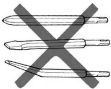
natural_image
Three crossed tool tips with a diagonal X mark, no text or symbols present4. Boltfastgøring med kemisk ankerjern (rotation + hamring)

natural_image
Technical line drawing of a drill bit with handle and screw (no text or symbols)○Adapter for bolt (vanlig hammer)
| Boltstørrelse |
| W1/4" |
| W5/16" |
| W3/8" |
| W1/2" |
| W5/8" |

Adapter for bolt (for vanlig hammer)


natural_image
Four crossed pencils and a pencil with a cross mark, no text or symbols present

natural_image
Technical line drawing of a drill bit with handle and screw (no text or symbols)natural_image
Technical line drawing of a drill bit with handle and screwdriver (no text or symbols)VEDLIKEHOLD OG KONTROLL
natural_image
Technical line drawing of a mechanical device with no visible text or symbolsnatural_image
Technical line drawing of a mechanical device with no visible text or symbols
Kiila
| Ulkohalkaisija |
| 11,0 mm |
| 12,3 mm |
| 12,7 mm |
| 14,3 mm |
| 14,5 mm |
| 17,5 mm |
| 21,5 mm |
| Ankkurin koko |
| W1/4" |
| W5/16" |
| W3/8" |
| Ankkurin koko |
| W1/4" |
| W5/16" |
| W3/8" |
| W1/2" |
| W5/8" |

natural_image
Illustration of four different tools crossed out by a diagonal line, no text or symbols present
natural_image
Technical line drawing of a drill bit with handle and screw (no text or symbols)When using electric tools, basic safety precautions should always be followed to reduce the risk of fire, electric shock and personal injury, including the following.
Read all these instructions before operating this product and save these instructions. For safe operations:
- Keep work area clean. Cluttered areas and benches invite injuries.
- Consider work area environment. Do not expose power tools to rain. Do not use power tools in damp or wet locations. Keep work area well lit.
Do not use power tools where there is risk to cause fire or explosion. - Guard against electric shock. Avoid body contact with earthed or grounded surfaces. (e.g. pipes, radiators, ranges, refrigerators).
- Keep children and infirm persons away. Do not let visitors touch the tool or extension cord. All visitors should be kept away from work area.
- Store idle tools. When not in use, tools should be stored in a dry, high or locked up place, out of reach of children and infirm persons.
- Do not force the tool. It will do the job better and safer at the rate for which it was intended.
- Use the right tool. Do not force small tools or attachments to do the job of a heavy duty tool. Do not use tools for purposes not intended; for example, do not use circular saw to cut tree limbs or logs.
- Dress properly. Do not wear loose clothing or jewelry, they can be caught in moving parts. Rubber gloves and non-skid footwear are recommended when working outdoors. Wear protecting hair covering to contain long hair.
- Use eye protection. Also use face or dust mask if the cutting operation is dusty.
- Connect dust extraction equipment. If devices are provided for the connection of dust extraction and collection facilities ensure these are connected and properly used.
- Do not abuse the cord. Never carry the tool by the cord or yank it to disconnect it from the receptacle. Keep the cord away from heat, oil and sharp edges.
- Secure work. Use clamps or a vise to hold the work. It is safer than using your hand and it frees both hands to operate tool.
- Do not overreach. Keep proper footing and balance at all times.
- Maintain tools with care. Keep cutting tools sharp and clean for better and safer performance. Follow instructions for lubrication and changing accessories. Inspect tool cords periodically and if damaged, have it repaired by authorized service center. Inspect extension cords periodically and replace, if damaged. Keep handles dry, clean, and free from oil and grease.
- Disconnect tools. When not in use, before servicing, and when changing accessories such as blades, bits and cutters.
-
Remove adjusting keys and wrenches. Form the habit of checking to see that keys and adjusting wrenches are removed from the tool before turning it on.
-
Avoid unintentional starting. Do not carry a plugged-in tool with a finger on the switch. Ensure switch is off when plugging in.
- Use outdoor extension leads. When tool is used outdoors, use only extension cords intended for outdoor use.
- Stay alert. Watch what you are doing. Use common sense. Do not operate tool when you are tired.
- Check damaged parts. Before further use of the tool, a guard or other part that is damaged should be carefully checked to determine that it will operate properly and perform its intended function. Check for alignment of moving parts, free running of moving parts, breakage of parts, mounting and any other conditions that may affect its operation. A guard or other part that is damaged should be properly repaired or replaced by an authorized service center unless otherwise indicated in this handling instructions. Have defective switches replaced by an authorized service center. Do not use the tool if the switch does not turn it on and off.
- Warning The use of any accessory or attachment, other than those recommended in this handling instructions, may present a risk of personal injury.
- Have your tool repaired by a qualified person. This electric tool is in accordance with the relevant safety requirements. Repairs should only be carried out by qualified persons using original spare parts. Otherwise this may result in considerable danger to the user.
PRECAUTIONS ON USING ROTARY HAMMER
- Wear earplugs to protect your ears during operation.
- Do not touch the bit during or immediately after operation. The bit becomes very hot during operation and could cause serious burns.
- Before starting to break, chip or drill into a wall, floor or ceiling, thoroughly confirm that such items as electric cables or conduits are not buried inside.
- Always hold the body handle and side handle of the power tool firmly. Otherwise the counterforce produced may result in inaccurate and even dangerous operation.
SPECIFICATIONS
| Voltage (by areas)* (110V, 230V) | ~ |
| Power Input 720W* | |
| No-load speed | 0 – 1050 min-1 |
| Full-load impact rate | 0 – 4600 min-1 |
| Capacity: concrete 3.4 – 24 mmsteel 13 mmwood 32 mm | |
| Weight (without cord and side handle) 2.8 kg | |
| Dust collecting adapterMax. hole-drilling depth: 100 mm (adjustment possible between 0 and 100 mm)Diameter of drill: 3.4 – 24 mmMax. length of drill (overall length): 270 mm | |
| Dustbag capacity: 0.4 liters |
*Be sure to check the nameplate on product as it is subject to change by areas.
STANDARD ACCESSORIES
(1) Case (Molded plastic)....1
(2) Side handle .... 1
(3) Dust collecting adapter .... 1
(4) Dust bag 1
[Numbers (3) and (4) refer to use on concrete]
(5) Cap 1
Standard accessories are subject to change without notice.
OPTIONAL ACCESSORIES (sold separately)
1. Drilling anchor holes (rotation + hammering)
○Drill bit (Slender shaft)

| Drill bit (slender shaft) | ||
| Outer diameter Effective length Overall length | ||
| 3.4 mm | 45 mm 90 mm | |
| 3.5 mm | ||

natural_image
Technical line drawing of a mechanical device with no visible text or symbols○Drill bit (Taper shank) and taper shank adapter

Cotter
| Outer diameter |
| 11.0 mm |
| 12.3 mm |
| 12.7 mm |
| 14.3 mm |
| 14.5 mm |
| 17.5 mm |
| 21.5 mm |
| Taper mode | Applicable drill bit | |
| Morse taper (No.1) | Drill bit (taper shank) | 11.0 ~ 17.5 mm |
| Morse taper (No.2) | Drill bit (taper shank) | 21.5 mm |
| A-taper | Taper shank adapter formed A-taper or B-taper is provided as an optional accessory, but the drill bit for it is not provided. | |
| B-taper | ||
○13 mm rotary hammer chuck
For drilling operations when using a straight shank bit for impact drilling with a rotary hammer.

2. Anchor setting (rotation + hammering)
○Anchor setting adapter (for rotary hammer)


Anchor setting adapter (SDS-plus shank) (for rotary hammer)
Overall length: 160, 260 mm
| Anchor size |
| W1/4" |
| W5/16" |
| W3/8" |

natural_image
Technical line drawing of a drill bit with handle and screw (no text or symbols)○Anchor setting adapter (for manual hammer)
| Anchor size |
| W1/4" |
| W5/16" |
| W3/8" |
| W1/2" |
| W5/8" |



Anchor setting adapter (for manual Hammer)
3. Crushing operation (rotation + hammering)
Bull point (Round type only) (SDS-plus shank)

natural_image
Four crossed tool illustrations, one with a pen and three with a cross mark (no text or symbols)

natural_image
Technical line drawing of a drill bit with handle and screwdriver (no text or symbols)- Bolt placing operation with Chemical Anchor. (rotation + hammering)
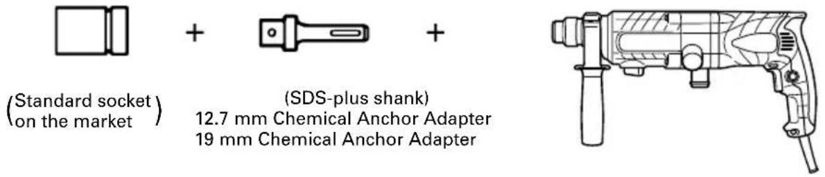
- Drilling holes and driving screws (rotation only)
○Drill chuck, chuck adapter (G), special screw and chuck wrench

- Drilling holes (rotation only)

○ 13 mm drill chuck ass'y (includes chuck wrench) and chuck (for drilling in steel or wood).
- Driving Screws (rotation only)

| Bit No. Screw Size Length | ||
| No. 2 3 – 5 | mm 25 mm | |
| No. 3 6 – 8 | mm 25 mm | |
8. Dust cup, Dust collector (B)

Dust cup

Dust collector (B)
9. Paper dust bag

10. Hammer grease A
500 g (in a can)
70 g (in a green tube)
30 g (in a green tube)
Optional accessories are subject to change without notice.
APPLICATIONS
Rotation and hammering function
○Drilling anchor holes
○Drilling holes in concrete
○Drilling holes in tile
Rotation only function
○Drilling in steel or wood (with optional accessor)
○Tightening machine screws, wood screws (with optional accessories)
PRIOR TO OPERATION
1. Power source
Ensure that the power source to be utilized conforms to the power requirements specified on the product nameplate.
2. Power switch
Ensure that the power switch is in the OFF position. If the plug is connected to a receptacle while the power switch is in the ON position, the power tool will start operating immediately, which could cause a serious accident.
3. Extension cord
When the work area is removed from the power source, use an extension cord of sufficient thickness and rated capacity. The extension cord should be kept as short as practicable.
4. Mounting the drill bit (Fig. 1)
CAUTION
To prevent accidents, make sure to turn the switch off and disconnect te plug from the receptacle.
NOTE
When using tools such as bull points, drill bits, etc., make sure to use the genuine parts designates by our company.
(1) Clean the shank portion of the drill bit.
(2) Insert the drill bit in a twisting manner into the tool holder until it latches itself (Fig. 1).
(3) Check the latching by pulling on the drill bit.
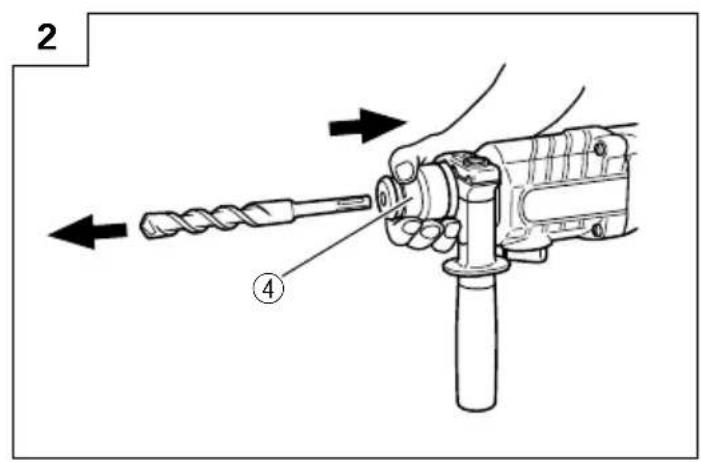
(4) To remove the drill bit, fully pull the grip in the direction of the arrow and pull out the drill bit (Fig. 2).
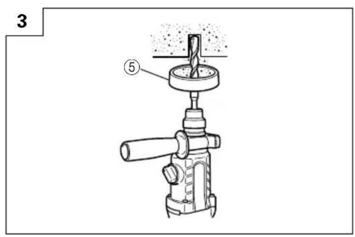
5. Installation of dust cup or dust collector (B) (Optional accessories) (Fig. 3, Fig. 4)
When using a rotary hammer or upward drilling operations attach a dust cup or dust collector (B) to collect dust or particles for easy operation.
○Installing the dust cup
Use the dust cup by attaching to the drill bit as shown in Fig. 3.
When using a bit which has big diameter, enlarge the center hole of the dust cup with this rotary hammer.
○Installing dust collector (B)
When using dust collector (B), insert dust collector (B) from the tip of the bit by aligning it to the groove on the grip (Fig. 4).
CAUTION
○The dust cup and dust collector (B) are for exclusive use of concrete drilling work. Do not use them for wood or metal drilling work.
○Insert dust collector (B) completely into the chuck part of the main unit.
When turning the rotary hammer on while dust collector (B) is detached from a concrete surface, dust collector (B) will rotate together with the drill bit. Make sure to turn on the switch after pressing the dust cup on the concrete surface. (When using dust collector (B) attached to a drill bit that has more than 190 mm of overall length, dust collector (B) cannot touch the concrete surface and will rotate. Therefore please use dust collector (B) by attaching to drill bits which have 166 mm, 160 mm, and 110 mm overall length.)
○Dump particles after every two or three holes when drilling.
○Please replace the drill bit after removing dust collector (B).
6. Selecting the driver bit
Screw heads or bits will be damaged unless a bit appropriate for the screw diameter is employed to drive in the screws.
7. Confirm the direction of bit rotation (Fig. 5)
The bit rotates clocwise (viewed from the rear side) by pushing the R-side of the push button. The L-side of the push button is pushed to turn the bit counterclockwise.
HOW TO USE
CAUTION
To prevent accidents, make sure to turn the switch off and disconnect the plug from the receptacle when the drill pits and other various parts are installed or removed. The power switch should also be turned off during a work break and after work.
1. Switch operation
The rotation speed of the drill bit can be controlled steplessly by varying the amount that the trigger switch is pulled. Speed is low when the trigger switch is pulled slightly and increases as the switch is pulled more. Continuous operation may be attained by pulling the trigger switch and depressing the stopper.
To turn the switch OFF, pull the trigger switch again to disengage the stopper, and release the trigger switch to its original position.
2. Rotation + hammering
This rotary hammer can be set to rotation and hammering mode by pressing the push button and turning the change lever to the T mark (Fig. 6).
(1) Mount the drill bit.
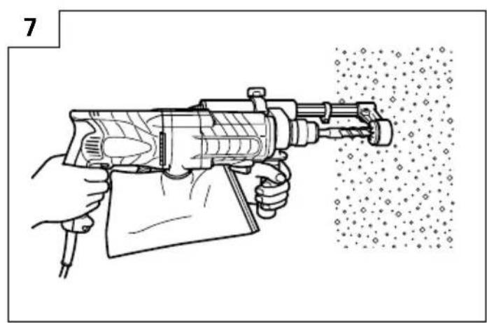
(2) Pull the trigger switch after applying the drill bit tip to the drilling position (Fig. 7).
(3) Pushing the rotary hammer forcibly is not necessary at all. Pushing slightly so that drill dust comes out gradually is sufficient.
CAUTION
When the drill bit touches construction iron bar, the bit will stop immediately and the rotary hammer will react to revolve. Therefore grip the side handle and handle tightly as shown in Fig. 7.
3. Using the dust-collecting adapter and dust bag
Using this unit with the dust-collecting adapter and dust bag attached creates a more hygienic working environment free of flying dust. Attach as shown in Fig. 8. The unit can be used as an ordinary rotary hammer when the dust-collecting adapter and dust bag are not attached.
(1) Attaching the dust-collecting adapter and the dust bag.
a) Attaching the dust-collecting adapter.
Loosen the knob on the side handle and insert the attachment rod on the dust-collecting adapter in the mounting hole. The adapter can be inserted from either direction A or B (see Fig. 9). Insert and push in the hose in the hose attachment hole of the main unit until it reaches the inner surface (depth 15mm ) and confirm that it is firmly fixed (see Fig. 10).
b) Attaching the dust bag.
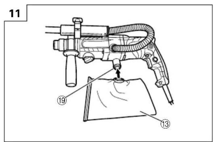
Insert the dust bag firmly in the dust bag attachment hole on the main unit and fasten securely (see Fig. 11).
CAUTION
○The dust-collecting adapter and dust bag is made for use when drilling concrete. Do not use for drilling holes in metal or wood.
(2) Adjusting the dust-collecting adapter.
a) Adjusting the position of the dust-collecting adapter. After firmly inserting the drill bit, loosen the wing bolt and drill bit tip and the end of the dust-collecting adapter in contact with each other (see Fig. 12).
b) Setting the hole-drilling depth.
Move the stopper to determine the stroke. The stroke is the hole-drilling depth (see Fig. 12).
○The maximum hole-drilling depth when using the dust-collecting adapter is 100 mm.
☐It is possible when using the dust-collecting adapter to use HITACHI drill bits up to a overall length of 216 mm. A hole-drilling depth of 45 mm will allow dust-collecting when the overall length of the drill bit is 116 mm.
(3) Drilling holes
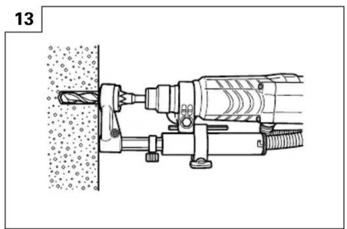
When drilling holes, secure the main unit so that the end of the dust-collecting adapter contacts with the concrete surface perfectly during drilling. Dust-collecting effectiveness is reduced if the adapter is not in contact with the surface (see Fig. 13).
(4) Removing dust
Excessive dust in the dust bag will reduce dust-collecting effectiveness. Remove dust from the dust bag regularly.
Remove the dust bag from the main unit, pull out the rail and throw away the dust and clean (see Fig. 14).
4. When not using the dust-collecting adapter
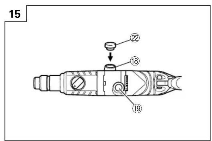
When removing the dust-collecting adapter and the dust bag to use as a normal rotary hammer, insert the provided cap in the hose attachment hole. (see Fig. 15). After removing the dust bag, the air blowing out from the attachment hole is reduced and no air will blow onto your face.
5. Rotation only
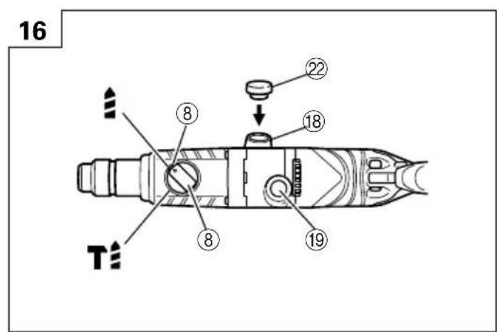
Remove the dust-collecting adapter as it cannot be used. Insert the provided cap in the hose attachment hole.
This rotary hammer can be set to rotation only mode by passing the push button and turning the change lever to the mark (Fig. 16).
To drill wood or metal material using the drill chuck and chuck adapter (optional accessories), proceed as follows.
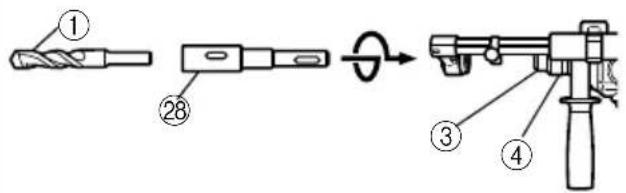
Installing drill chuck and chuck adapter: (Fig. 17)
(1) Attach the drill chuck to the chuck adapter.
(2) The part of the SDS-plus shank is the same as the drill bit. Therefore, refer to the item of "Mounting the drill bit" for attaching it.
CAUTION
○Application of force more than necessary will not only expedite the work, but will deteriorate the tip edge of the drill bit and reduce the service life of the rotary hammer in addition.
○Drill bits may snap off while withdrawing the rotary hammer from the drilled hole. For withdrawing, it is important to use a pushing motion.
○Do not attempt to drill anchor holes or holes in concrete with the machine set in the rotation only function.
○Do not attempt to use the rotary hammer in the rotation and striking function with the drill chuck and chuck adapter attached. This would seriously shorten the service life of every component of the machine.
6. When driving machine screws (Fig. 18)
First, insert the bit into the socket in the end of chuck adapter (D).
Next, mount chuck adapter (D) on the main unit using procedures described in 4 (1), (2), (3), put the tip of the bit in the slots in the head of the screw, grasp the main unit and tighten the screw.
CAUTION
Exercise care not to excessively prolong driving time, otherwise, the screws may be damaged by excessive force.
○Apply the rotary hammer perpendicularly to the screw head when driving the screw; otherwise, the screw head or bit will be damaged, or driving force will not be fully transferred to the screw.
○Do not attempt to use the rotary hammer in the rotation and striking function with the chuck adapter and bit attached.
7. When driving wood screws (Fig. 18)
(1) Selecting a suitable driver bit Employ plus-head screws, if possible, since the driver bit easily slips off the heads of minus-head screws.
(2) Driving in wood screws
○Prior to driving in wood screws, make pilot holes suitable for them in the wooden board. Apply the bit to the screw head grooves and gently drive the screws into the holes.
○After rotating the rotary hammer at low speed for a while until the wood screw is partly driven into the wood, squeeze the trigger more strongly to obtain the optimum driving force.
CAUTION
Exercise care in preparing a pilot hole suitable for the wood screw taking the hardness of the wood into consideration. Should the hole be excessively small or shallow, requiring much power to drive the screw into it, the thread of the wood screw may sometimes be damaged.
8. How to use the drill bit (taper shank) and the taper shank adapter
(1) Mount the taper shank adapter to the rotary hammer (Fig. 19).
(2) Mount the drill bit (taper shank) to the taper shank adapter (Fig. 19).
(3) Turn the switch ON, and drill a hole in prescribed depth.
(4) To remove the drill bit (taper shank), insert the cotter into the slot of the taper shank adapter and strike the head of the cotter with a hammer supporting on a rests (Fig. 20).
LUBRICATION
Low viscosity grease is applied to this rotary hammer so that it can be used for a long period without replacing the grease. Please contact the nearest service center for grease replacement when any grease is leaking form loosened screw.
Further use of the rotary hammer with lock off grease will cause the machine to seize up reduce the service life.
CAUTION
A special grease is used with this machine, therefore, the normal performance of the machine may be badly affected by use of other grease. Please be sure to let one of our service agents undertake replacement of the grease.
MAINTENANCE AND INSPECTION
1. Inspecting the drill bits
Since use of a dull tool will cause motor malfunctioning and degraded efficiency, replace the drill bit with new ones or resharpen them without delay when abrasion is noted.
2. Inspecting the mounting screws:
Regularly inspect all mounting screws and ensure that they are properly tightened. Should any of the screws be loose, retighten them immediately. Failure to do so could result in serious hazard.
3. Maintenance of the motor
The motor unit winding is the very "heart" of the power tool. Exercise due care to ensure the winding does not become damaged and/or wet with oil or water.
4. Inspecting the carbon brushes
For your continued safety and electrical shock protection, carbon brush inspection and replacement
on this tool should ONLY be performed by a Hitachi Authorized Service Center.
5. Service parts list
A: Item No.
B: Code No.
C: No. Used
D: Remarks
CAUTION
Repair, modification and inspection of Hitachi Power Tools must be carried out by a Hitachi Authorized Service Center.
This Parts List will be helpful it presented with the tool to the Hitachi Authorized Serivde Center when requesting repair or other maintenance.
In the operation and maintenance of power tools, the safety regulations and standards prescribed in each country must be observed.
MODIFICATIONS
Hitachi Power Tools are constantly being improved and modified to incorporate the latest technological advancements.
Accordingly, some parts (i.e. code numbers and/or design) may be changed without prior notice.
NOTE
Due to HITACHI's continuing program of research and development, the specifications herein are subject to change without prior notice.
Information concerning airborne noise and vibration The measured values were determined according to EN60745.
The typical A-weighted sound pressure level: 90 dB (A). The typical A-weighted sound power level: 103 dB (A).
Wear ear protection.
The typical weighted root mean square acceleration value: 8.6 m/s ^2 .

| A | B | C | D |
| 1 | 3 | 0 | 6 - 345 1 |
| 2 | 3 | 0 | 6 - 340 1 |
| 3 | 3 | 2 | 2 - 809 1 |
| 4 | 3 | 2 | 2 - 810 1 |
| 5 | 3 | 2 | 2 - 811 1 |
| 6 | 3 | 2 | 2 - 812 1 |
| 7 | 9 | 8 | 4 - 118 1 |
| 8 | 9 | 3 | 9 - 547 1 |
| 9 | 3 | 0 | 2 - 210 4 D5×90 |
| 10 | 322-786 1 | ||
| 11 | ——— | 1 | |
| 12 | 322-789 1 | ||
| 13 | 317-223 1 | ||
| 14 | 322-787 1 | ||
| 15 | 878-885 1 | S-18 | |
| 16 | 307-688 1 | ||
| 17 | 322-815 1 | ||
| 18 | 690-4DD 1 | 6904DDPS2L | |
| 19 | 322-819 1 | ||
| 20 | 322-813 1 | ||
| 21 | 959-156 1 | D7.0 | |
| 22 | 322-814 1 | ||
| 23 | 301-677 1 | ||
| 24 | 301-678 1 | ||
| 25 | 301-679 1 | ||
| 26 | 948-310 1 | ||
| 27 | 322-80301 | ||
| 28 | 944-486 1 | 1AP-20 | |
| 29 | 322-804 1 | ||
| 30 | 322-802 1 | ||
| 31 | 322-805 1 | ||
| 32 | 322-808 1 | ||
| 33 | 322-806 1 | ||
| 34 | 322-807 1 | ||
| 35 | 322-801 1 | ||
| 36 | 322-834 1 | I.D. 16 | |
| 37 | 322-800 1 | ||
| 38 | 322-793 1 | I.D. 66.5 | |
| 39 | 322-792 1 | ||
| 40 | 322-798 1 | ||
| 41 | 322-799 2 | ||
| 42 | 322-795 1 | ||
| 43 | 322-796 1 | ||
| 44 | 322-794 1 | ||
| 45 | 301-659 1 | ||
| 46 | 301-660 1 | ||
| 47 | 301-661 1 | ||
| 48 | 306-990 1 | ||
| 49 | 322-797 1 | ||
| 50 | 301-663 1 | ||
| 51 | 626-VVM 1 | 626VVC2PS2L | |
| 52 | 322-816 1 | ||
| 53 | 876-796 1 | P-22 | |
| 54 | 322-818 1 | ||
| 55 | 608-DDM 1 | 608DDC2PS2L | |
| 56 | 982-631 2 | ||
| 57 | 323-174 1 | ||
| 58 | 302-113 1 | ||
| 59 | 302-111 1 | ||
| 60 | 302-371 1 | ||
| 61 | 323-176 1 | ||
| 62 | 993-052 1 | ||
| 63 | 600-1DD 1 | 6001DDCMPS2L | |
| 64 | 302-372 1 |
| A | B | C | D |
| 65 323-175 1 | |||
| 66 302-114 1 | |||
| 67 1 360-646C | 1 | 110V-120V | |
| 67 2 360-646E | 1 | 220V-230V | |
| 68 322-791 1 | |||
| 69 981-421 2 | D4×55 | ||
| 70 1 340-581C | 1 | 110V-120V | |
| 70 2 340-581E | 1 | 220V-230V | |
| 71 608-VVM | 1 | 608VVC2PS2L | |
| 72 322-832 1 | |||
| 73 | — | 1 | |
| 74 322-790 1 | |||
| 75 | — | 1 | |
| 76 999-088 2 | |||
| 77 308-536 2 | |||
| 78 306-945 4 | D3×10 | ||
| 79 322-838 2 | |||
| 80 1 322-827 1 | |||
| 80 2 322-828 1 | “GBR(110V)” | ||
| 81 1 322-830 1 | |||
| 81 2 322-831 1 | “GBR(110V)” | ||
| 82 322-823 2 | |||
| 83 1 322-820 1 | 110V-127V | ||
| 83 2 322-825 1 | 220V-240V | ||
| 84 930-039 1 | |||
| 85 981-373 2 | |||
| 86 953-327 1 | D8.8 | ||
| 87 | — | 1 | |
| 88 937-631 1 | |||
| 89 984-750 2 | D4×16 | ||
| 90 301-653 2 | D4×20 | ||
| 91 322-833 1 | |||
| 92 302-074 1 | “93-99” | ||
| 93 302-077 1 | |||
| 94 302-075 1 | |||
| 95 301-801 1 | M6×27 | ||
| 96 303-159 1 | M4×25.5 | ||
| 97 872-470 1 | S-26 | ||
| 98 302-076 1 | “99” | ||
| 99 873-095 1 | P-16 | ||
| 100 302-386 1 | |||
| 101 302-048 1 | “100” | ||
| 501 323-177 1 | |||
| 502 303-659 1 | |||
| 503 302-374 1 |
natural_image
Simple line drawing of a quill pen with inkwell (no text or symbols)
natural_image
Line drawing of a quill pen in an inkwell (no text or symbols)| Svenska | Suomi | ||
| EF-DEKLARATION BETRÄFFANDE LIKFORMIGHETVi tillkännagiver med eget ansvar att denna produkt överensstämmer med standard eller standardiserat dokument EN60745, EN55014 och EN61000-3 i enlighet med råddirektiven 73/23/E∅S, 89/336/E∅S och 98/37/ EF.Denna deklaration gäller för CE-märkningen på produkten. | EY-ILMOITUS YHDENMUKAISUUDESTAYksinomaisella vastuudella vakuutamme, että tämä tuote vastaa normeja tai normitettuja dokumentteja EN60745, EN55014 ja EN61000-3 yhteisön ohjeiden 73/ 23/ETY, 89/336/ETY ja 98/37/EY mukaisesti.Tämä ilmoitus sovelletaan tuotekohtaiseen CE- merkintään. | ||
| Dansk | English | ||
| EF-DEKLARATION OM ENSARTETHEDVi erlkærer os fuldstændige ansvarlige for, at dette produkt modsvarer gældende standard eller de standardiserede dokumenter EN60745, EN55014 og EN61000-3 i overensstemmelse med EF-direktiver 73/ 23/E∅F, 89/336/E∅S og 98/37/EF.Denne erklæring qælder produkter, der er mærket med CE. | EC DECLARATION OF CONFORMITYWe declare under our sole responsibility that this product is in conformity with standards or standardized documents EN60745, EN55014 and EN61000-3 in accordance with Council Directives 73/23/EEC, 89/336/ EEC and 98/37/EC.This declaration is applicable to the product affixed CE marking. | ||
| Norsk | |||
| EF'S ERKLÆRING OM OVERENSSTEMMELSEVierklærerherved at vi påtar oss eneansvaret for at dette produktet er i overensstermmelse med normer eller standardiserte dokumenter EN60745, EN55014 og EN61000-3 i samsvar med Rådsdirektiver 73/23/E∅S, 89/336/E∅S og 98/37/EF.Denne erklæringen gjelder produktets påklistrede CE- merking. | |||
| Representative office in Europe Hitachi Power Tools Europe GmbH Siemensring 34, 47877 Willich 1, F. R. Germany Head office in Japan Hitachi Koki Co., Ltd.Shinagawa Intercity Tower A, 15-1, Konan 2-chome, Minato-ku, Tokyo, Japan | CE 31. 3. 2004M. KatoK. KatoBoard Director | ||

Hitachi Koki Co., Ltd.
- Boltfastgøring med kemisk ankerjern (rotation + hamring)
- VEDLIKEHOLD OG KONTROLL
- PRECAUTIONS ON USING ROTARY HAMMER
- STANDARD ACCESSORIES
- OPTIONAL ACCESSORIES (sold separately)
- Drilling anchor holes (rotation + hammering)
- ○13 mm rotary hammer chuck
- Anchor setting (rotation + hammering)
- Crushing operation (rotation + hammering)
- Dust cup, Dust collector (B)
- Paper dust bag
- Hammer grease A
- APPLICATIONS
- PRIOR TO OPERATION
- Power source
- Power switch
- Extension cord
- Mounting the drill bit (Fig. 1)
- CAUTION
- NOTE
- Installation of dust cup or dust collector (B) (Optional accessories) (Fig. 3, Fig. 4)
- Selecting the driver bit
- Confirm the direction of bit rotation (Fig. 5)
- HOW TO USE
- Switch operation
- Rotation + hammering
- Using the dust-collecting adapter and dust bag
- When not using the dust-collecting adapter
- Rotation only
- When driving machine screws (Fig. 18)
- When driving wood screws (Fig. 18)
- How to use the drill bit (taper shank) and the taper shank adapter
- LUBRICATION
- MAINTENANCE AND INSPECTION
- Inspecting the drill bits
- Inspecting the mounting screws:
- Maintenance of the motor
- Inspecting the carbon brushes
- Service parts list
- MODIFICATIONS
- Hitachi Koki Co., Ltd.
Brand : HITACHI
Model : DH 24PD2
Category : Drill