
LE 14-11 125 - Angle Grinder Flex - Free user manual and instructions
Find the device manual for free LE 14-11 125 Flex in PDF.


| Brand | Flex |
| Model | LE 14-11 125 |
| Product type | Angle grinder |
| Disc diameter | 125 mm |
| Rated power | 1400 W |
| Supply voltage | 230 V ~ 50 Hz |
| No-load speed | 11,000 rpm |
| Weight | 2.8 kg |
| Dimensions (L x W x H) | 300 x 120 x 100 mm |
| Cable length | 2.5 m |
| Main functions | Grinding, cutting, brushing, deburring |
| Included accessories | Grinding disc, tightening key, auxiliary handle |
| Safety | Restart protection, overload protection, adjustable protective guard |
| Maintenance and cleaning | Clean ventilation slots regularly, check carbon brushes |
| Spare parts and repairability | Available from the manufacturer, high repairability index |
| Sound level (LpA) | 92 dB(A) |
| Vibration level | 6.5 m/s² |
| Protection class | Class II |
| Chuck type | M14 |
| Recommended use | DIY, construction site, metalworking |
Frequently Asked Questions - LE 14-11 125 Flex
User questions about LE 14-11 125 Flex
0 question about this device. Answer the ones you know or ask your own.
Ask a new question about this device
Download the instructions for your Angle Grinder in PDF format for free! Find your manual LE 14-11 125 - Flex and take your electronic device back in hand. On this page are published all the documents necessary for the use of your device. LE 14-11 125 by Flex.
USER MANUAL LE 14-11 125 Flex
natural_image
Illustration of a power tool with a gray and white workpiece, no text or symbols present(L 14-11 115, L 14-11 125,
LE 14-11 115, LE 14-11 125: Handgriff
(LE 9-11 125, LE 14-11 115,
LE 14-11 125)
natural_image
Close-up of a power tool with a hammer and screwdriver, showing the process of angleing operation (no text or symbols visible)
HINWEIS
natural_image
Mechanical assembly diagram showing a shaft and housing with labeled components A (no text or symbols beyond labels)natural_image
Close-up of a mechanical component with a black plastic housing and directional arrow indicator (no readable text or symbols)natural_image
Close-up of a car's side panel showing a black plastic component with directional arrows indicating movement (no text or symbols)natural_image
Illustration of hands using a grinding tool to cut a workpiece on a workbench (no text or symbols visible)Eckhard Rühle Manager Research & Development (R & D)
Klaus Peter Weinper Head of Quality Department (QD)
Symbols used in this manual ..... 16
Symbols on the power tool 16
For your safety 16
Noise and vibration 19
Technical specifications 20
Overview 22
Instructions for use 23
Maintenance and care 26
Disposal information 26
(€-Declaration of Conformity ..... 26
Exemption from liability 27
Symbols used in this manual

WARNING!
Denotes impending danger. Non-observance of this warning may result in death or extremely severe injuries.

CAUTION!
Denotes a possibly dangerous situation. Non-observance of this warning may result in slight injury or damage to property.

NOTE
Denotes application tips and important information.
Symbols on the power tool

Before switching on the power tool, read the operating manual!

Wear goggles!

Protection class II (completely insulated)

Disposal information for the old machine (see page 26)!

Prevents kickback of the machine if the tool becomes blocked.

Overload protection: switches the machine off in the event of overload.

A tachogenerator prevents the speed from falling under load.

Better work safety and improved handling thanks to gentle speed development.

Sensor-controlled temperature monitoring: If there is a risk of overheating the machine switches off.

Prevents unintentional machine start after a power failure.

The speed can be set variably in 6 stages.

Brake system reduces run-on period of tool.

Micro-processor electronics
For your safety

WARNING!
Before using the angle grinder, please read and follow:
– these operating instructions,
- the "General safety instructions" on the handling of power tools in the enclosed booklet (leaflet-no.: 315.915),
– the currently valid site rules and the regulations for the prevention of accidents.
This angle grinder is state of the art and has been constructed in accordance with the acknowledged safety regulations.
Nevertheless, when in use, the power tool may be a danger to life and limb of the user or a third party, or the power tool or other property may be damaged. The angle grinder may be operated only if it is
- as intended,
– in perfect working order.
Faults which impair safety must be repaired immediately.
Intended use
This angle grinder
– for commercial use in industry and trade,
– is designed for dry grinding and cutting metal and stone; a special cutting guard must be used for cutting,
– for use with grinding tools and accessories which are indicated in these instructions or recommended by the manufacturer.
Not permitted are e.g. chain cutting wheels, saw blades.
Safety Warnings for Angle Grinder

WARNING!
Read all safety warnings and all instructions. Failure to follow the warnings and instructions may result in electric shock, fire and/or serious injury. Save all warnings and instructions for future reference.
Safety Warnings Common for Grinding or Abrasive Cutting-Off Operations
■ This power tool is intended to function as a grinder or cut-off tool. Read all safety warnings, instructions, illustrations and specifications provided with this power tool. Failure to follow all instructions listed below may result in electric shock, fire and/or serious injury.
■ Operations such as sanding, wire brushing or polishing are not recommended to be performed with this power tool. Operations for which the power tool was not designed may create a hazard and cause personal injury.
■ Do not use accessories which are not specifically designed and recommended by the tool manufacturer. Just because the accessory can be attached to your power tool, it does not assure safe operation.
■ The rated speed of the accessory must be at least equal to the maximum speed marked on the power tool. Accessories running faster than their rated speed can break and fly apart.
■ The outside diameter and the thickness of your accessory must be within the capacity rating of your power tool. Incorrectly sized accessories cannot be adequately guarded or controlled.
- Threaded mounting of accessories must match the grinder spindle thread. For accessories mounted by flanges, the arbour hole of the accessory must fit the locating diameter of the flange.
Accessories that do not match the mounting hardware of the power tool will run out of balance, vibrate excessively and may cause loss of control. - Do not use a damaged accessory. Before each use inspect the accessory such as abrasive wheels for chips and cracks, backing pad for cracks, tear or excess wear, wire brush for loose or cracked wires. If power tool or accessory is dropped, inspect for damage or install an undamaged accessory. After inspecting and installing an accessory, position yourself and bystanders away from the plane of the rotating accessory and run the power tool at maximum no-load speed for one minute. Damaged accessories will normally break apart during this test time.
■ Wear personal protective equipment. Depending on application, use face shield, safety goggles or safety glasses. As appropriate, wear dust mask, hearing protectors, gloves and workshop apron capable of stopping small abrasive or workpiece fragments. The eye protection must be capable of stopping flying debris generated by various operations. The dust mask or respirator must be capable of filtrating particles generated by your operation. Prolonged exposure to high intensity noise may cause hearing loss. - Keep bystanders a safe distance away from work area. Anyone entering the work area must wear personal protective equipment. Fragments of workpiece or of a broken accessory may fly away and cause injury beyond immediate area of operation.
- Hold the power tool by insulated gripping surfaces only, when performing an operation where the cutting accessory may contact hidden wiring or its own cord. Cutting accessory contacting a “live” wire may make exposed metal parts of the power tool “live” and could give the operator an electric shock.
■ Position the cord clear of the spinning accessory. If you lose control, the cord may be cut or snagged and your hand or arm may be pulled into the spinning accessory.
■ Never lay the power tool down until the accessory has come to a complete stop. The spinning accessory may grab the surface and pull the power tool out of your control.
- Do not run the power tool while carrying it at your side. Accidental contact with the spinning accessory could snag your clothing, pulling the accessory into your body.
- Regularly clean the power tool's air vents. The motor's fan will draw the dust inside the housing and excessive accumulation of powdered metal may cause electrical hazards.
■ Do not operate the power tool near flammable materials. Sparks could ignite these materials.
■ Do not use accessories that require liquid coolants. Using water or other liquid coolants may result in electrocution or shock.
Kickback and Related Warnings
Kickback is a sudden reaction to a pinched or snagged rotating wheel, backing pad, brush or any other accessory. Pinching or snagging causes rapid stalling of the rotating accessory which in turn causes the uncontrolled power tool to be forced in the direction opposite of the accessory's rotation at the point of the binding. For example, if an abrasive wheel is snagged or pinched by the workpiece, the edge of the wheel that is entering into the pinch point can dig into the surface of the material causing the wheel to climb out or kick out. The wheel may either jump toward or away from the operator, depending on direction of the wheel's movement at the point of pinching. Abrasive wheels may also break under these conditions. Kickback is the result of power tool misuse and/or incorrect operating procedures or conditions and can be avoided by taking proper precautions as given below.
■ Maintain a firm grip on the power tool and position your body and arm to allow you to resist kickback forces. Always use auxiliary handle, if provided, for maximum
control over kickback or torque reaction during start-up.
The operator can control torque reactions or kickback forces, if proper precautions are taken.
■ Never place your hand near the rotating accessory. Accessory may kickback over your hand.
- Do not position your body in the area where power tool will move if kickback occurs. Kickback will propel the tool in direction opposite to the wheel's movement at the point of snagging.
■ Use special care when working corners, sharp edges etc. Avoid bouncing and snagging the accessory. Corners, sharp edges or bouncing have a tendency to snag the rotating accessory and cause loss of control or kickback.
■ Do not attach a saw chain woodcarving blade or toothed saw blade. Such blades create frequent kickback and loss of control.
Safety Warnings Specific for Grinding and Abrasive Cutting-Off Operations
■ Use only wheel types that are recommended for your power tool and the specific guard designed for the selected wheel. Wheels for which the power tool was not designed cannot be adequately guarded and are unsafe.
■ The grinding surface of centre depressed wheels must be mounted below the plane of the guard lip. An improperly mounted wheel that projects through the plane of the guard lip cannot be adequately protected.
■ The guard must be securely attached to the power tool and positioned for maximum safety, so the least amount of wheel is exposed towards the operator. The guard helps to protect the operator from broken wheel fragments, accidental contact with wheel and sparks that could ignite clothing.
- Wheels must be used only for recommended applications. For example: do not grind with the side of cut-off wheel.
Abrasive cut-off wheels are intended for peripheral grinding; side forces applied to these wheels may cause them to shatter.
■ Always use undamaged wheel flanges that are of correct size and shape for your selected wheel. Proper wheel flanges support the wheel thus reducing the possibility of wheel breakage. Flanges for cut-off wheels may be different from grinding wheel flanges.
■ Do not use worn down wheels from larger power tools. Wheel intended for larger power tool is not suitable for the higher speed of a smaller tool and may burst.
Additional Safety Warnings specific for Abrasive Cutting-Off Operations
- Do not “jam” the cut-off wheel or apply excessive pressure. Do not attempt to make an excessive depth of cut. Overstressing the wheel increases the loading and susceptibility to twisting or binding of the wheel in the cut and the possibility of kickback or wheel breakage.
■ Do not position your body in line with and behind the rotating wheel. When the wheel, at the point of operation, is moving away from your body, the possible kickback may propel the spinning wheel and the power tool directly at you.
■ When wheel is binding or when interrupting a cut for any reason, switch off the power tool and hold the power tool motionless until the wheel comes to a complete stop. Never attempt to remove the cut-off wheel from the cut while the wheel is in motion otherwise kickback may occur. Investigate and take corrective action to eliminate the cause of wheel binding.
- Do not restart the cutting operation in the workpiece. Let the wheel reach full speed and carefully re-enter the cut. The wheel may bind, walk up or kickback if the power tool is restarted in the workpiece.
■ Support panels or any oversized workpiece to minimize the risk of wheel pinching and kickback. Large workpieces tend to sag under their own weight. Supports must be placed under the workpiece near the line of cut and near the edge of the workpiece on both sides of the wheel.
- Use extra caution when making a “pocket cut” into existing walls or other blind areas. The protruding wheel may cut gas or water pipes, electrical wiring or objects that can cause kickback.
Additional safety instructions
■ The mains voltage and the voltage specifications on the rating plate must correspond.
■ Do not press the spindle lock until the grinding tool stops.
Noise and vibration

NOTE
Values for the A-weighted sound pressure level and for the total vibration values can be found in the “Technical specifications” table.
The noise and vibration values have been determined in accordance with EN 60745.

CAUTION!
The indicated measurements refer to new power tools. Daily use causes the noise and vibration values to change.

NOTE
The vibration emission level given in this information sheet has been measured in accordance with a standardised test given in EN 60745 and may be used to compare one tool with another. It may be used for a preliminary assessment of exposure. The declared vibration emission level represents the main applications of the tool. However if the tool is used for different applications, with different accessories or poorly maintained, the vibration emission may differ. This may significantly increase the exposure level over the total working period. However if the tool is used for different applications, with different accessories or poorly maintained, the vibration emission may differ. This may significantly decrease the exposure level over the total working period.
Identify additional safety measures to protect the operator from the effects of vibration such as: maintain the tool and the accessories, keep the hands warm, organisation of work patterns.

CAUTION!
ear protection at a sound pressure above 85 dB(A).
Technical specifications
| L 8-11 115 L | 8-11 125 LE | 9-11 125 L 10-11 125 | |||
| Machine type Angle grinderr | |||||
| Max. grinding tool ∅ | mm | 115 125 | |||
| Grinding tool thickness | mm | 1-6 | |||
| Shaft thread | mm | 22.23 | |||
| Spindle thread M14 | |||||
| Speed | r.p.m. | 11,500 6,000-11,500 11,500 | |||
| Power input | W | 800 900 1050 | |||
| Power output | W | 460 600 650 | |||
| Weight according to “EPTA Procedure 01/2003” (without power cord) | kg | 2.0 2.1 | |||
| Protection class | II/☐ | ||||
| A-weighted sound pressure level according to EN 60745 (see “Noise and vibration”): | |||||
| Sound pressure level L_pA | dB(A) | 86.4 87 85 | |||
| Sound power level L_WA | dB(A) | 97.4 98 96 | |||
| Uncertainty K | db | 3.0 | |||
| Total vibration value according to EN 60745 (see “Noise and vibration”): | |||||
| Emission value a_h when grinding surfaces | m/s2 | 7.7 | 8.5 | 6.3 | |
| Emission value a_h when cutting-off | m/s2 | 3.0 1.6 | |||
| Uncertainty K | m/s2 | 1.5 | |||
| L 14-11 115 L | 14-11 125 LE 1 | 4-11 115 LE 14 | 11 125 | ||
| Machine type Angle grinderr | |||||
| Max. grinding tool ∅ | mm | 115 125 | 115 125 | ||
| Grinding tool thickness | mm | 1-6 | |||
| Shaft thread | mm | 22.23 | |||
| Spindle thread M14 | |||||
| Speed | r.p.m. | 11,500 2,800-11,500 | |||
| Power input | W | 1400 | |||
| Power output | W | 880 | |||
| Weight according to “EPTA Procedure 01/2003” (without power cord) | kg | 2.3 | |||
| Protection class | II/☐ | ||||
| A-weighted sound pressure level according to EN 60745 (see “Noise and vibration”): | |||||
| Sound pressure level L_pA | dB(A) | 86 | |||
| Sound power level L_WA | dB(A) | 97 | |||
| Uncertainty K | db | 3.0 | |||
| Total vibration value according to EN 60745 (see “Noise and vibration”): | |||||
| Emission value a_h when grinding surfaces | m/s^2 | 6.3 | |||
| Emission value a_h when cutting-off | m/s^2 | 1.4 | |||
| Uncertainty K | m/s^2 | 1.5 | |||
Overview
Different electric power tools are described in these instructions. The illustrated electric power tool may differ in detail from the one which you purchased.

1 Spindle
2 Threaded flange
a Clamping nut
b Clamping flange
3 Guard hood
Can be adjusted without a tool through 360^ by means of 12 notches.
a) 115 mm (L 8-11 115, L 14-11 115, LE 14-11 115)
b) 125 mm
4 Handle
Handle can be fitted to the left or right. (L 14-11 115, L 14-11 125, LE 14-11 115, LE 14-11 125: handle with integrated pin wrench)
5 Spindle lock
Secures the spindle when the tool is changed.
6 Gear head
With air outlet and direction-of-rotation arrow.
7 Switch rocker
Switches the power tool on and off. With notched position for continuous operation.
8 Rear handle
9 Dial for preselecting the speed (LE 9-11 125, LE 14-11 115, LE 14-11 125)
10 4.0 m power cord with plug
11 Rating plate (not illustrated)
12 Face spanner
Instructions for use

WARNING!
Before carrying out any work on the angle grinder, always pull out the mains plug.
Before switching on the power tool
Unpack the angle grinder and check that there are no missing or damaged parts.
Attach the guard

WARNING!
When using the angle grinder for roughing or cutting, never work without the guard. A special cutting guard must be used for cutting.
■ Pull out the mains plug.
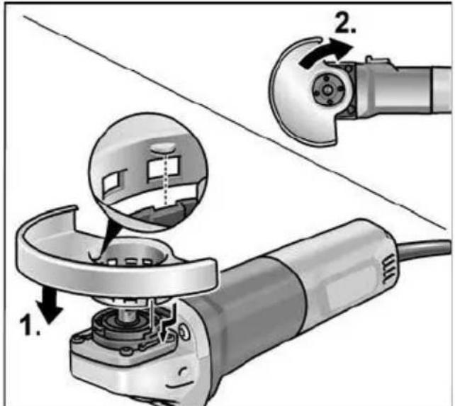
■ Attach the guard (1.). Lugs on the guard hood must be located in the flange recesses (2.).
■ Turn guard hood clockwise.
Rotation is possible in one direction only!
■ Remove in reverse order.
Attach the handle

natural_image
Close-up of a power tool with a grating and handle, showing mechanical components (no text or symbols visible)
NOTE
It is not permitted to operate the electric power tool without the handle.
Attaching/changing the tool
■ Pull out the mains plug.
Attach the grinding wheel

■ Press and hold down the spindle lock (1.).
■ Using the face spanner, loosen the clamping nut on the spindle in an anticlockwise direction and remove (2.).
Handle
(L 14-11 115, L 14-11 125, LE 14-11 115, LE 14-11 125)
■ Remove the handle from the power tool by rotating it in an anti-clockwise direction.

natural_image
Mechanical component diagram showing a shaft and housing with rotational arrows labeled A (no text or symbols beyond labels)■ Rotate the cover on the handle by 180^ until it engages.
■ The stop key is released.
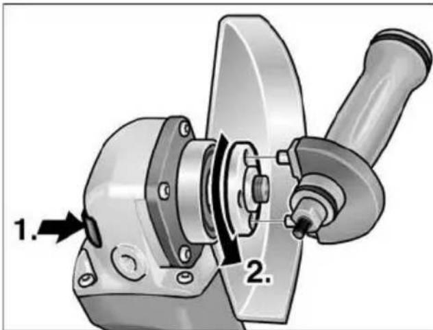
■ Press and hold down the spindle lock (1.).
■ Using the stop key, loosen the clamping nut on the spindle in an anti-clockwise direction and remove (2.).

■ Insert the grinding wheel in the correct position.
■ Screw the clamping nut with flange face up, onto the spindle.
■ Press and hold down the spindle lock.
■ Tighten the clamping nut with the pin wrench or stop key.
- Carry out a test run to check that the tool is clamped in the centre.
Test run
■ Insert the mains plug into the socket.
■ Switch on the angle grinder with the switch (without engaging it) and run the angle grinder for approx. 30 seconds. Check for imbalances and vibrations.
■ Switch off the angle grinder.
Switching on and off Brief operation without engaged switch rocker

natural_image
Close-up of a car's internal component with a black plastic connector and directional arrow (no text or symbols)■ Push the switch rocker forwards and hold in position.
■ To switch off the power tool, release the switch rocker.
Continuous operation with engaged switch rocker
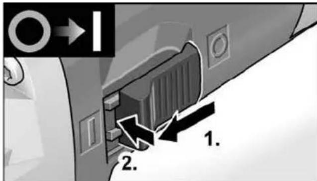
■ Push the switch rocker forwards (1.) and engage by pressing the front end (2.).
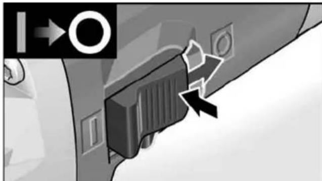
natural_image
Close-up of a car's side panel with a black plastic clip and directional arrows indicating movement (no text or symbols)■ To switch off the power tool, release the switch rocker by pressing the rear end.
i NOTE
Following a power failure, the switched on power tool does not restart.
Preselecting the speed (LE 9-11 125, LE 14-11 115, LE 14-11 125)

■ To set the operating speed, move the dial to the required value.
CAUTION!
Risk of injury due to destruction of the tool. Use the appropriate tool for the job.
i NOTE
If an overload or overheating occurs during continues operation, the power tool automatically reduces the speed until the power tool has cooled down adequately.
Adjusting the guard
To adjust the tool to the task at hand, the guard hood can be adjusted by 12 notches on 360^ without a tool.
CAUTION!
Risk of injury! Wear protective gloves.
■ Pull out the mains plug.
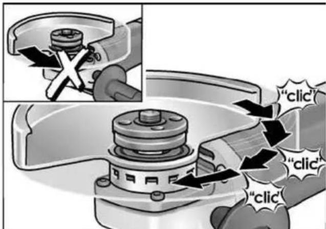
■ Turn guard hood opposite to the direction-of-rotation arrow on the gear head to the required position.
Work instructions
i NOTE
When the power tool is switched off, the grinding tool continues running briefly.
Rough-grinding
WARNING!
Never use cutting-off wheels for rough-grinding.
- Angle of wheel 20–40° for best cutting performance. - Applying moderate pressure, move the angle grinder backwards and forwards. As a result, the workpiece will not become too hot and there will be no discoloration; nor will there be any grooves.
Cut-off grinding
WARNING!
A special cutting guard must be used for cutting.
See manufacturer's accessories catalogue.
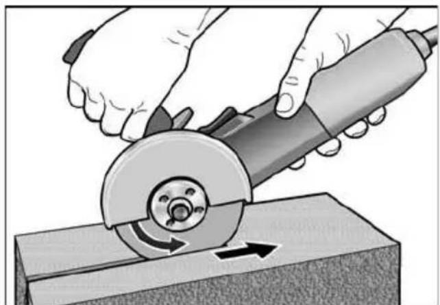
- Do not press, tilt or oscillate the power tool.
- The angle grinder must always be operated backwards.
natural_image
Illustration of hands using a grinding tool to cut a workpiece on a workbench (no text or symbols visible)Otherwise, there is a risk of the angle grinder jumping uncontrollably out of the groove.
- Adjust the feed to the material which is to be cut: the harder the material, the slower the feed.
For further information on the manufacturer's products go to www.flex-tools.com.
Maintenance and care

WARNING!
Before carrying out any work on the angle grinder, always pull out the mains plug.
Cleaning

WARNING!
If metals are ground or cut over a prolonged period, conductive dust may become deposited inside the housing. Impairment of the protective insulation! Operate the power tool via a residual-current-operated circuit-breaker (tripping current 30 mA).
■ Regularly clean the power tool and ventilation slots. Frequency of cleaning is dependent on the material and duration of use.
■ Regularly blow out the housing interior and motor with dry compressed air.
Carbon brushes
The angle grinder features cut-off carbon brushes.
When the wear limit of the cut-off carbon brushes is reached, the angle grinder switches off automatically.

NOTE
Use only original parts supplied by the manufacturer for replacement purposes. If non-original parts are used, the guarantee obligations of the manufacturer will be deemed null and void.
When the power tool is being used, the carbon brushes can be seen sparking through the rear air inlet apertures. If the carbon brushes spark excessively, switch off the angle grinder immediately. Take the angle grinder to a customer service workshop authorised by the manufacturer.
Gears

NOTE
Do not loosen the screws on the gear head during the warranty period. Non-compliance will deem the guarantee obligations of the manufacturer null and void.
Repairs
Repairs may be carried out by an authorised customer service centre only.
Spare parts and accessories
For other accessories, in particular grinding tools, see the manufacturer's catalogues. Exploded drawings and spare-part lists can be found on our homepage: www.flex-tools.com
Disposal information

WARNING!
Render redundant power tools unusable by removing the power cord.

EU countries only Do not throw electric power tools into the household waste!
In accordance with the European Directive 2012/19/EU on Waste Electrical and Electronic Equipment and transposition into national law used electric power tools must be collected separately and recycled in an environmentally friendly manner.

NOTE
Please ask your dealer about disposal options!
CE-Declaration of Conformity
We declare under our sole responsibility that the product described under “Technical specifications” conforms to the following standards or normative documents:
EN 60745 in accordance with the regulations of the directives 2014/30/EU 2006/42/EC, 2011/65/EU.
Responsible for technical documents:
Eckhard Rühle
Manager Research &
Development (R & D)
Klaus Peter Weinper
Head of Quality
Department (QD)
05.11.2018
Exemption from liability
The manufacturer and his representative are not liable for any damage and lost profit due to interruption in business caused by the product or by an unusable product. The manufacturer and his representative are not liable for any damage which was caused by improper use of the product or by use of the product with products from other manufacturers.
Table des matières
1 Broche
2 Flasque taraudé
a Ecrou de serrage
b Bride de serrage
3 Capot de protection
a) 115 mm (L 8-11 115, L 14-11 115,
LE 14-11 115)
b) 125 mm
4 Poignée
(L 14-11 115, L 14-11 125, LE 14-11
natural_image
Illustration of a grinding tool with a spoke and handle, showing angle adjustment (no text or symbols)
REMARQUE
natural_image
Mechanical assembly diagram showing a shaft and housing with rotational arrows labeled A (no text or symbols beyond labels)natural_image
Close-up of a car's side panel showing a black plastic connector and a directional arrow (no text or symbols)natural_image
Close-up of a car's side panel with a black plastic clip and directional arrows indicating movement (no text or symbols)natural_image
Illustration of hands using a grinding tool to cut a workpiece on a block (no text or symbols visible)Eckhard Rühle Manager Research & Development (R & D)
Klaus Peter Weinper Head of Quality Department (QD)
05/11/2018
1 A l b e r i n o
2 Flangia filettata
natural_image
Close-up of a power tool with a grinding press and angle tool (no text or symbols visible)
AVVISO
natural_image
Mechanical assembly diagram showing a shaft and housing with labeled components A (no text or symbols beyond labels)natural_image
Close-up of a mechanical component with a black plastic connector and directional arrow indicator (no text or symbols)natural_image
Close-up of a car's side panel with a black plastic clip and directional arrows indicating movement (no text or symbols)natural_image
Illustration of hands using a grinding tool to cut a workpiece on a block (no text or symbols visible)Eckhard Rühle
Manager Research & Development (R & D)
Klaus Peter Weinper
Head of Quality
Department (QD)
05/11/2018
1 Husillo
2 Acoplamiento a rosca
a Tuerca de montaje
(L 14-11 115, L 14-11 125,
LE 14-11 115, LE 14-11 125:
natural_image
Close-up of a white electric grinder with a tool inserted, showing the blade and handle (no text or symbols visible)
NOTA
natural_image
Mechanical component diagram showing a shaft and housing with rotational arrows labeled A (no text or symbols beyond labels)natural_image
Close-up of a car's front panel showing a black connector with a white arrow pointing to the next panel (no text or symbols visible)natural_image
Illustration of hands using a grinding tool to cut a workpiece on a block (no text or symbols visible)Eckhard Rühle
Manager Research & Development (R & D)
Klaus Peter Weinper
Head of Quality Department (QD)
05/11/2018
(L 14-11 115, L 14-11 125,
natural_image
Close-up of a power tool with a grinding press and angle tool (no text or symbols visible)
INDICAÇÃO
natural_image
Mechanical assembly diagram showing a shaft and housing with labeled components A (no text or symbols beyond labels)natural_image
Close-up of a car's front panel showing a black connector and a directional arrow (no text or symbols)natural_image
Close-up of a car's side panel showing a black plastic clip and directional arrows (no text or symbols)natural_image
Illustration of hands using a grinding tool on a workbench (no text or symbols visible)Eckhard Rühle
Manager Research & Development (R & D)
Klaus Peter Weinper Head of Quality Department (QD)
05/11/2018
1 Uitgaande as
2 Schroefdraadflens
a Spanmoer
a Spanflens
3 Beschermkap
a) 115 mm (L 8-11 115, L 14-11 115,
LE 14-11 115)
b) 125 mm
4 Handgreep
(L 14-11 115, L 14-11 125,
natural_image
Illustration of a power tool with a hammer and screwdriver, showing the process of angleing operation (no text or symbols present)
LET OP
natural_image
Mechanical component diagram showing a shaft and housing with labeled rotation arrows (no text or symbols beyond labels A)natural_image
Close-up of a mechanical component with a black plastic connector and directional arrow indicator (no text or symbols)natural_image
Close-up of a car's side panel with a black plastic clip and directional arrows indicating movement (no text or symbols)natural_image
Illustration of hands using a grinding tool to cut a workpiece on a block (no text or symbols visible)Manager Research & Development (R & D)
Klaus Peter Weinper
Head of Quality Department (QD)
05-11-2018
1 Spindel
2 Gevindflange
a Spændemøtrik
b Spændeflange
a) 115 mm (L 8-11 115, L 14-11 115,
LE 14-11 115)
b) 125 mm
4 Håndgreb
(L 14-11 115, L 14-11 125,
LE 14-11 115, LE 14-11 125: Håndtag
(LE 9-11 125, LE 14-11 115,
LE 14-11 125)
10 Netkabel 4,0 m med netstik
11 Typeskilt (ikke vist)
12 Topnøgle
Brugsanvisning

ADVARSEL!
natural_image
Close-up of a power tool with a grinding press and angle tool (no text or symbols visible)
BEMAERK
natural_image
Mechanical component diagram showing a shaft and housing with labeled rotation arrows (A), no text or symbols present.natural_image
Close-up of a mechanical component with a black arrow pointing to a section, no visible text or symbols■ Skub vippekontakten fremad og hold den fast.
■ Slip vippekontakten for at slukke.
natural_image
Close-up of a car's side panel showing a mounted sensor or connector with directional arrows (no text or symbols)■ Frigør vippekontakten ved at trykke på bagerste ende for at slukke.
i BEMAERK
natural_image
Illustration of hands using a grinding tool to cut a workpiece on a workbench (no text or symbols visible)Eckhard Rühle Manager Research & Development (R & D)
Klaus Peter Weinper Head of Quality Department (QD)
05-11-2018
1 Spindel
2 Gjengeflens
a Spennmutter
b Spennflens
3 Vernehette
a) 115 mm (L 8-11 115, L 14-11 115,
LE 14-11 115)
b) 125 mm
4 Håndtak
(L 14-11 115, L 14-11 125,
LE 14-11 115, LE 14-11 125: Håndtak
(LE 9-11 125, LE 14-11 115,
LE 14-11 125)
10 Nettkabel 4,0 m med støpsel
11 Typeskilt (ikke framstilt)
12 Tappnøkkel
Bruksanvisning

ADVARSEL!
Før alle arbeider med vinkelsliperen må strømkabelen trekkes ut.
Før ibruktaking
natural_image
Close-up of a power tool with a grinding press and angle tool (no text or symbols visible)
HENVISNING
natural_image
Mechanical component diagram showing a shaft and housing with rotational arrows labeled A (no text or symbols beyond labels)natural_image
Close-up of a mechanical component with a black plastic connector and directional arrow (no text or symbols visible)– Bruk skråvinkel 20–40° for best sliping.
natural_image
Illustration of hands using a grinding tool to cut a workpiece on a block (no text or symbols visible)Eckhard Rühle
Manager Research &
Development (R & D)
05.11.2018
Klaus Peter Weinper
Head of Quality
Department (QD)
1 Spindel
2 Gängad fläns
a Spännmutter
b Spännfläns
3 Skyddskåpa
a) 115 mm (L 8-11 115, L 14-11 115,
LE 14-11 115)
b) 125 mm
4 Handtag
(L 14-11 115, L 14-11 125,
LE 14-11 115, LE 14-11 125: Handtag
(LE 9-11 125, LE 14-11 115,
LE 14-11 125)
natural_image
Illustration of a grinding tool with a spoke and handle, showing angle adjustment (no text or symbols)
OBS
natural_image
Mechanical component diagram showing a shaft and housing with rotational arrows labeled A (no text or symbols beyond labels)natural_image
Close-up of a car's side panel showing a black plastic clip inserted into the door, with an arrow pointing to the left side (no text or symbols visible)natural_image
Close-up of a car's side panel with a lock and directional arrows indicating motion (no text or symbols)natural_image
Illustration of hands using a grinding tool to cut a workpiece on a workbench (no text or symbols visible)Eckhard Rühle
Manager Research &
Development (R & D)
Klaus Peter Weinper
Head of Quality
Department (QD)
2018-11-05
1 K a r a
2 Kierrelaippa
a Kiinnitysmutteri
b Kiinnityslaippa
3 S u o j u s
a) 115 mm (L 8-11 115, L 14-11 115,
LE 14-11 115)
b) 125 mm
4 Käsikahva
(L 14-11 115, L 14-11 125,
(LE 9-11 125, LE 14-11 115,
LE 14-11 125)
natural_image
Close-up of a grimping machine with a tool inserted, showing the blade and handle (no text or symbols visible)
OHJE
natural_image
Mechanical component diagram showing a shaft and housing with rotational arrows labeled A (no text or symbols beyond labels)natural_image
Close-up of a car's front panel showing a black connector and a directional arrow (no text or symbols)natural_image
Close-up of a car's side panel with a black plastic clip and directional arrows indicating movement (no text or symbols)natural_image
Illustration of hands using a grinding tool on a workbench (no text or symbols visible)Eckhard Rühle
Manager Research & Development (R & D)
05.11.2018
Klaus Peter Weinper
Head of Quality
Department (QD)
1 A T ρ α κ τ ο ζ
(L 14-11 115, L 14-11 125,
LE 14-11 115, LE 14-11 125:
natural_image
Close-up of a power tool with a grating and handle, showing mechanical components (no text or symbols visible)
ΥΠΟΔΕΙΞΗ
(L 14-11 115, L 14-11 125,
natural_image
Mechanical component diagram showing a shaft and housing with rotational arrows labeled A (no text or symbols beyond labels)natural_image
Close-up of a mechanical component with a black plastic connector and directional arrow indicator (no readable text or symbols)natural_image
Illustration of hands using a grinding tool to cut a workpiece on a wooden block (no text or symbols)Eckhard Rühle
Manager Research &
Development (R & D)
Klaus Peter Weinper
Head of Quality
Department (QD)
05.11.2018
1 W r z e c i o n o
a) 115 mm (L 8-11 115, L 14-11 115,
LE 14-11 115)
b) 125 mm
4 Uchwyt
(L 14-11 115, L 14-11 125,
LE 14-11 115, LE 14-11 125: Uchwyt
natural_image
Illustration of a power tool with a grinding press and angle tool (no text or symbols)
WSKAZÓWKA
natural_image
Mechanical component diagram showing a shaft and housing with rotational arrows labeled A (no text or symbols beyond labels)natural_image
Close-up of a mechanical component with a black plastic clip inserted, showing a circular arrow and directional indicator (no text or symbols on the object itself)natural_image
Illustration of hands using a grinding tool to cut a workpiece on a stone block (no text or symbols visible)1 O r s ó
2 Menetes karima
a Szorító anya
b Szorító perem
3 Védősapka
a) 115 mm (L 8-11 115, L 14-11 115,
LE 14-11 115)
b) 125 mm
4 Kézi fogantyú
(L 14-11 115, L 14-11 125,
natural_image
Close-up of a power tool with a grating and a handle, showing mechanical components (no text or symbols visible)
MEGJEGYZÉS
(L 14-11 115, L 14-11 125,
natural_image
Mechanical component diagram showing a shaft and housing with rotational arrows labeled A (no text or symbols beyond labels)natural_image
Close-up of a car's front panel showing a black plastic connector and a directional arrow (no text or symbols)natural_image
Close-up of a car's side panel showing a black connector with directional arrows indicating movement (no text or symbols)natural_image
Illustration of hands using a grinding tool to cut a circular cutter on a workbench (no text or symbols visible)Eckhard Rühle
Manager Research &
Development (R & D)
Klaus Peter Weinper
Head of Quality
Department (QD)
-
- 05
1 V ř e t e n o
2 Závitová příruba
a Upínací matice
b Upínací příruba
3 Ochranný kryt
a) 115 mm (L 8-11 115, L 14-11 115,
LE 14-11 115)
b) 125 mm
4 Rukojet'
(L 14-11 115, L 14-11 125,
natural_image
Close-up of a power tool with a grinding press and angle tool (no text or symbols visible)
UPOZORNĚNÍ
(L 14-11 115, L 14-11 125,
natural_image
Mechanical component diagram showing a shaft and housing with rotational arrows labeled A (no text or symbols beyond labels)natural_image
Close-up of a car's side panel showing a black plastic clip inserted into the door, with an arrow pointing to the left side (no text or symbols visible)natural_image
Close-up of a car's side panel with a black plastic buckle and directional arrows indicating movement (no text or symbols)natural_image
Illustration of hands using a grinding tool to cut a workpiece on a workbench (no text or symbols visible)Eckhard Rühle
Manager Research &
Development (R & D)
Klaus Peter Weinper
Head of Quality
Department (QD)
05.11.2018
1 V r e t e n o
2 Závitová príruba
a Upínacia matica
b Upínacia príruba
3 Ochranný kryt
a) 115 mm (L 8-11 115, L 14-11 115,
LE 14-11 115)
b) 125 mm
4 Rukovät'
natural_image
Close-up of a power tool with a grinding press and angle tool (no text or symbols visible)
UPOZORNENIE
natural_image
Mechanical assembly diagram showing a shaft and housing with labeled components A (no text or symbols beyond labels)natural_image
Close-up of a mechanical component with a black plastic connector and directional arrow indicator (no text or symbols)natural_image
Close-up of a car's side panel with a black plastic clip and directional arrows indicating movement (no text or symbols)natural_image
Illustration of hands using a grinding tool to cut a circular cutter on a workbench (no text or symbols visible)Eckhard Rühle
Manager Research &
Development (R & D)
Klaus Peter Weinper
Head of Quality
Department (QD)
05.11.2018
1 Spindel
2 Keermega äärik
a Kinnitusmutter
b Kinnitusäärik
3 Kaitsekate
a) 115 mm (L 8-11 115, L 14-11 115,
LE 14-11 115)
b) 125 mm
4 Käepide
(L 14-11 115, L 14-11 125,
LE 14-11 115, LE 14-11 125: inte-
natural_image
Close-up of a power tool with a grating and a workpiece, showing mechanical components (no text or symbols visible)
MÄRKUS
natural_image
Mechanical component diagram showing a shaft and housing with rotational arrows labeled A (no text or symbols beyond labels)natural_image
Close-up of a mechanical component with a black plastic connector and directional arrow indicator (no readable text or symbols)natural_image
Close-up of a car's side panel showing a black plastic clip and directional arrows (no text or symbols)natural_image
Illustration of hands using a grinding tool to cut a workpiece on a workbench (no text or symbols visible)Eckhard Rühle Manager Research & Development (R & D) 05.11.2018
Klaus Peter Weinper Head of Quality Department (QD)
1 Velenas
2 Srieginé jungè
a Tvirtinimo veržlė
b Tvirtinimo flanšas
3 Apsauginis gaubtas
a) 115 mm (L 8-11 115, L 14-11 115,
LE 14-11 115)
b) 125 mm
4 Rankena
(L 14-11 115, L 14-11 125,
LE 14-11 115, LE 14-11 125: rankena
natural_image
Illustration of a power tool with a grinding press and angle tool (no text or symbols)
NURODYMAS
(L 14-11 115, L 14-11 125,
natural_image
Mechanical component diagram showing a shaft and housing with rotational arrows labeled A (no text or symbols beyond labels)natural_image
Close-up of a mechanical component with a black plastic connector and directional arrow indicator (no readable text or symbols)natural_image
Close-up of a car's side panel with a black plastic clip and directional arrows indicating movement (no text or symbols)natural_image
Illustration of hands using a grinding tool to cut a workpiece on a block (no text or symbols visible)Eckhard Rühle
Manager Research & Development (R & D)
Klaus Peter Weinper
Head of Quality Department (QD)
2018-11-05
1 Darbvārpsta
2 Vitnatloks
a) 115 mm (L 8-11 115, L 14-11 115,
LE 14-11 115)
b) 125 mm
4 R o k t u r i s
(L 14-11 115, L 14-11 125,
(LE 9-11 125, LE 14-11 115,
LE 14-11 125)
natural_image
Close-up of a power tool with a grating and a handle, showing mechanical components (no text or symbols visible)
NORĀDĪJUMS
Lietot elektroinstrumentu bez roktura nav atlauts.
natural_image
Mechanical assembly diagram showing a shaft and housing with labeled components A (no text or symbols beyond labels)natural_image
Close-up of a mechanical component with a black connector and directional arrow indicator (no readable text or symbols)natural_image
Close-up of a car's side panel with a black connector and directional arrows indicating movement (no text or symbols)natural_image
Illustration of hands using a grinding tool on a workbench (no text or symbols visible)Eckhard Rühle
Manager Research &
Development (R & D)
Klaus Peter Weinper
Head of Quality
Department (QD)
05.11.2018
1 Ш п и н д е л ь
2 Резьбовой фланец
а Зажимная гайка
b Зажимной фланец
3 Защитный кожух
(L 14-11 115, L 14-11 125,
LE 14-11 115, LE 14-11 125: рукоятка
natural_image
Close-up of a power tool with a grinding press and angle tool (no text or symbols visible)
ПРИМЕЧАНИЕ
natural_image
Mechanical component diagram showing a shaft and housing with rotational arrows labeled A (no text or symbols beyond labels)natural_image
Close-up of a mechanical component with a black plastic connector and directional arrow indicator (no readable text or symbols)natural_image
Close-up of a car's side panel showing a black plastic component with directional arrows indicating movement (no text or symbols)natural_image
Illustration of hands using a grinding tool to cut a workpiece on a block (no text or symbols visible)Eckhard Rühle Manager Research & Development (R & D)
Klaus Peter Weinper Head of Quality Department (QD)
05.11.2018


- HINWEIS
- Symbols used in this manual
- WARNING!
- CAUTION!
- NOTE
- Symbols on the power tool
- For your safety
- Intended use
- Safety Warnings for Angle Grinder
- Safety Warnings Common for Grinding or Abrasive Cutting-Off Operations
- Kickback and Related Warnings
- Safety Warnings Specific for Grinding and Abrasive Cutting-Off Operations
- Additional Safety Warnings specific for Abrasive Cutting-Off Operations
- Additional safety instructions
- Noise and vibration
- Overview
- Instructions for use
- Before switching on the power tool
- Attach the guard
- Attaching/changing the tool
- Handle
- Test run
- Switching on and off Brief operation without engaged switch rocker
- Continuous operation with engaged switch rocker
- i NOTE
- Adjusting the guard
- Work instructions
- Rough-grinding
- Cut-off grinding
- Maintenance and care
- Cleaning
- Carbon brushes
- Gears
- Repairs
- Spare parts and accessories
- Disposal information
- CE-Declaration of Conformity
- Exemption from liability
- Table des matières
- REMARQUE
- AVVISO
- NOTA
- INDICAÇÃO
- LET OP
- Brugsanvisning
- ADVARSEL!
- BEMAERK
- i BEMAERK
- Bruksanvisning
- Før ibruktaking
- HENVISNING
- OBS
- OHJE
- ΥΠΟΔΕΙΞΗ
- WSKAZÓWKA
- O r s ó
- Menetes karima
- Védősapka
- Kézi fogantyú
- MEGJEGYZÉS
- UPOZORNĚNÍ
- UPOZORNENIE
- MÄRKUS
- NURODYMAS
- NORĀDĪJUMS
- ПРИМЕЧАНИЕ
Brand : Flex
Model : LE 14-11 125
Category : Angle Grinder