PGM1006 - Generator Ferm - Free user manual and instructions
Find the device manual for free PGM1006 Ferm in PDF.


| Product Type | Portable Generator |
| Brand | Ferm |
| Model | PGM1006 |
| Dimensions (W x H x D) | 500 x 400 x 400 mm |
| Weight | 28 kg |
| Power Source | Petrol Engine |
| Fuel Type | Unleaded Petrol |
| Maximum Output Power | 1000 W |
| Rated Output Power | 900 W |
| Output Voltage | 230 V |
| Frequency | 50 Hz |
| Engine Type | 4-Stroke, OHV, 72cc |
| Fuel Tank Capacity | 4 L |
| Oil Capacity | 0.6 L |
| Starting Method | Recoil Start |
| Noise Level | 96 dB(A) |
| Run Time at 50% Load | 8 hours |
| Fuel Consumption | 0.5 L/h |
| Circuit Breaker | Yes |
| Outlets | 1 x 230V Schuko socket |
| Usage | Home backup, camping, outdoor |
| Maintenance | Oil change, air filter cleaning, spark plug check |
| Safety Features | Low oil shutdown, overload protection |
| Warranty | 2 years |
Frequently Asked Questions - PGM1006 Ferm
User questions about PGM1006 Ferm
0 question about this device. Answer the ones you know or ask your own.
Ask a new question about this device
Download the instructions for your Generator in PDF format for free! Find your manual PGM1006 - Ferm and take your electronic device back in hand. On this page are published all the documents necessary for the use of your device. PGM1006 by Ferm.
USER MANUAL PGM1006 Ferm
EXPLODEDVIEWE
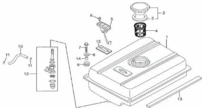
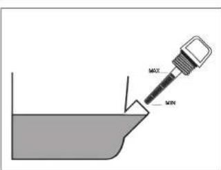
Fig.2
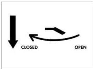
flowchart
graph TD
    A["↓"] --> B["CLOSED"]
    B --> C["←"]
    C --> D["OPEN"]
Fig. 4
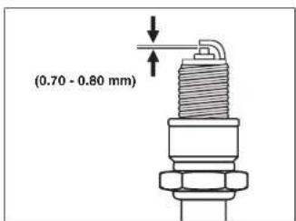
Fig. 3
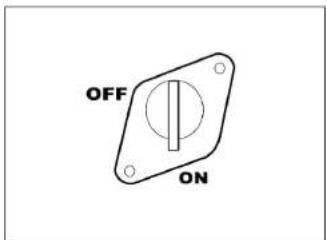
Fig. 5

GENERATOR (4 STROKE)
THE NUMBERS IN THE FOLLOWING TEXT CORRESPOND WITH THE PICTURES AT PAGE2+3
SA FET YAND OPERATING INSTRUCTIONS

For your own safety and for the safety of others, please read these
instructions carefully before using
this appliance. It will help you understand
your product more easily and avoid
unnecessary risks. Keep this instruction
manual in a safe place for future use.
CONTENTS:
- Machine data
- Safety instructions
- Use
- Service & maintenance
1. MACHINEDATA
INTRODUCTION
The generator is designated to generate electricity with help of a 4 stroke fuel engine. Now you can use your electric tools in the field in spite of the lack of the electricity grid.
AVR
The AVR-system Automatic Voltage Regulator) inside this generator produces a stable and precise voltage output.
TECHNICALSPECIFICATION
Rated voltage IAC230V
Rated frequency (AC) 150 Hz
Rated output | 2000W
Max. output power
of apparatus 12200 W
Tool class
Weight 144 kg
Dimensions
Outdoornoise(Lwa) 194,0dB(A)
Sound pressure capacity(Lpa) | 65,0dB(A)
Type Engine
Cylinder arrangement
cylinder
Continuous
Max. output 14.8 kW
Operation hours | 13 hours
Fuel
Fuel tank capacity | 15 L
Engine oil capacity 1600 ml
Spark contact
point distance|0.7-0.8mm
FEATURES
Fig.1
- Fuel tank
- Fuel level indicator
- Fuel cap
- Exhaust
- AC socket
- Ground terminal
- AC Switch
- Oil filler cap
- Oil drain plug
- Oil sensor
11.Voltmeter - Engine switch
- Choke lever
- Recoil starter
- Fuel tap
- Air filter cover
- Spark plug
Unleaded

SPAREPARTS LIST
| NO. | DESCRIPTION | POSITION |
| 203078 | GASKET SET CYLINDERHEAD | A3, 12 |
| 203079 | SPARK PLUG | A10 |
| 203080 | SPARK PLUG WRENCH | A15, 16 |
| 203081 | GASKET SET CARBURATOR | B14, 15, 17 |
| 203082 | AIR FILTER COMPLETE | C10 |
| 203083 | GASKET SET EXHAUST | D5, 11 |
| 203084 | FUEL CAP | E2, 3 |
| 203086 | FILTER | E4 |
| 203092 | FUEL GAUGE | E5 |
| 203091 | GASKET | E15 |
| 203087 | MOTOR SUPPORT | F2 |
| 203089 | MOTOR SUPPORT | F3 |
| 203085 | RUBBER FOOTF6, 7 | |
| 400890 | ENGINE SWITCH | - |
| 400891 | CIRCUIT BREAKER SWITCH | - |
| 203093 | CARBON BRUSH WITH HOLDER | - |
EXPLODED VIEWA

2. SAFETYINSTRUCTIONS
Explanation of symbols
In this manual and/or on the machine the following symbols are used:

In accordance with essential applicable safety standards of European directives

Risk of damaging material and/or physical injuries

Risk of an electric shock

Read instruction manual

Keep bystanders away

Do not expose to rain

Outdoornoise

Risk of high temperature Caution: the generator contains some parts which might reach high temperatures

Faulty and/or discarded electrical or electronic apparatus have to be collected at the appropriate recycling locations.
SAFETYINSTRUCTIONS
Persons
- Never allow children or people unfamiliar with these instructions to use the appliance. Local regulations may restrict the age of the operator.
- Always operate outdoors with good ventilation. Exhaust gas contains poisonous carbon monoxide.
• Always stop the engine before refilling the fuel tank and clean the machine after filling
the fuel tank.
• Do not inhale fumes from petrol.
Electricity
- Do not touch the generator if you have wet hands
- Do not operate the generator in wet conditions.
- Do not operate the generator near water.
- Never connect two generators together.
- Never connect the generator to any commercial power outlet.
- Make sure any extension cords used are in a safe condition and of sufficient capacity for the task.
- Ensure that the load on the generator falls within its capacity as specified in the table before plugging in any cords.
Fire and burn hazards
• The exhaust system gets hot enough to ignite some materials:
- keep the generator at least 1 meter away from buildings and other equipment during operation.
- keep flammable materials away from the generator.
- The exhaust becomes very hot during operations and remains hot for a while after stopping the engine:
- Let the engine cool before storing the generator indoors.
-
Do not touch the hot exhaust with your hands.
-
Gasoline is extremely flammable and is explosive under certain conditions. Do not smoke or allow flames or sparks where the generator is refueled or where gasoline is stored.
- Fuel vapors are extremely flammable and may ignite after the engine has started. Make sure that any spilled fuel has been wiped up before starting the generator.
- Never shade the generator with clothes or other articles.
3. USE
BEFORE STARTING THE GENERATOR

Ground terminal
The generator ground terminal is connected to the frame of the generator, the metal/non-current-carrying parts of the generator, and the ground terminals of each receptacle. Before using the ground terminal, consult a qualified electrician, electrical inspector or local agency having jurisdiction for local codes or ordinances that apply to the intended use of the generator.
Fill and check oil level (quantity is 600 ml) Always check the oil level (with machine in a level position) before starting and if the engine unexpectedly stops (fig. 2).
For general use you can use an "all temperature" oil 10W-30
≤0°C SAE#10
0°C - 25°C SAE#20
25°C -35°C SAE#30
≥35°C SAE#40
Fill and check fuel level
• Use unleaded fuel only
- Remove any power cords
- Turn power switches off
- Do not overfill—leave air gap at top of fuel level
• Always screw down fuel cap
- Clean up any spilled fuel
- Do not smoke while operating the generator

Always use caution!
Starting the generator
Fig. 1+4+5
- Turn on fuel tap (15)
- Turn on engine switch (12).
- Move choke lever (13) to closed position (to restart a warm engine, leave the choke lever in open or half-open position).
- Pull slowly on the starter cord until it engages, then pull sharply to start the
engine(14)
- Allow the engine to run until it warms up, and then move the choke lever to the open position (13).
Using the ACOutput(230V)
- Start the generator.
- Plug in the electrical appliance plug.
- Press AC current protector downward to "ON"(7).
- The voltmeter (11) displays the voltage on the AC socket. Normally this should be ± 230 V during use.
Stopping the generator
Fig. 1+5
- Unplug all cords (5)
- Turn engine switch to "OFF" (12)
- Turn off fuel tap (15)
4. SERVICE & MAINTENANCE
PERIODIC MAINTENANCE
Daily (pre-operation check)
- Check engine oil level
- Check fuel hose for cracks or other damage. Replace if necessary.
- Check exhaust-system for leakage. Retighten or replace gasket if necessary.
- Check choke operation
- Check recoil starter operation
1st Month or 20hrs
- Replace engine oil
3 Months or 50 hrs
- Check condition of spark plug. Adjust gap and clean. Replace if necessary.
- Clean, replace if necessary.
6 Months or 100 hrs
- Replace engine oil
- Clean fuel tap and fuel tank filter. Replace if necessary.
- Check fittings and fasteners. Replace if necessary.
12 Months or 300 hrs
- Contact a specialized service centre to check the valve clearance.
- Check the fan of the cooling system for damage.
CE DICHIARAZIONE DI CON FORMITÀ (I)
Service - notes on maintenance Fig.1
Oil replacement
• Warm up engine on level ground
- Remove filler cap (8)
- Open drain plug (9) and let oil drain completely into a pan placed under the engine.
- Check gaskets, replace if required. Refit drain plug and refill engine with clean oil.
- Replace filler cap.
Spark plug inspection
Fig.3
- Disconnect the spark plug cap, and remove any dirt from around the spark plug area.
- Remove spark plug (17) with the plug spanner supplied.
- Inspect the spark plug. It should be a tan colour.
- Measure the gap (distance contact point) with a suitable gauge. The gap should be 0,7 - 0,8 mm. Correct the gap, if necessary, by carefully bending the side electrode.
- Replace the spark plug if the electrodes are worn, or if the insulator is cracked or chipped.
- Install the spark plug carefully, by hand, to avoid cross-threading.
- Place the spark plug with correct torque: 20 Nm.
- Attach the spark plug cap.
Exhaustscreen
- Wait for exhaust to cool.
- Exhaust screen may be blocked up with carbon deposits.
- Undo the screw cap and remove the exhaust screen.
- Clean the screen with a wire brush and refit.
- Replace exhaust screen if damaged.
Air filtercleaning
- Remove the air filter cover (16).
- Remove filter element and wash well in solvent.
- Pour a small amount of oil onto the filter element and gently squeeze out any excess oil.
- Replace the filter element and air filter cover.
- Be sure the filter cover seals properly all around.

Do not run the engine without the air filter element in place.

Never place a wet filter (with solvent) on the machine.
Fueltap
• To remove the fuel tap filter, simply undo the cup at the bottom of the fuel tank
- Use a small spanner to remove the tap
- Clean and wash out the filter and cup, and replace.
TROUBLESHOOTING
Basic checks
• Make sure you have plenty of fuel
• Make sure the fuel tap is on
• Make sure the engine-switch is on
• Make sure the oil level is correct
- The generator has an oil sensor. When the oil level is too low, the generator will not be able to start.
- Remove spark plug, connect spark plug lead and earth it to the generator. Pull starter cord gently and look for a spark. If there is no spark, replace spark plug.
Spark plug is OK, but engine still won't start
- Check fuel tap filter is clean
- Check fuel line is clear
- Check carburetor is not clogged
Engine will not start
• Clean or replace spark plug
- Check ignition system—if faulty, contact your service centre
- Check compression – if low, contact your service centre
- Check for loose cylinder head – tighten bolts
- Check for damaged cylinder head gasket – replace if necessary
CLEANING
Clean the housing regularly with a soft cloth, preferably every time it is used. Keep the air vents free of dust and dirt.
Remove stubborn dirt with a soft rag moistened in soapy water. Do not use any solvents such as petrol, alcohol, ammonia, etc. as such substances can damage the plastic parts.
STORAGE(LONGTERM)
- Drain fuel tank, fuel tap, carburetor bowl and carburetor
- Pour 1 cup of engine oil into the fuel tank and shake the generator to spread the oil around the tank. Drain excess oil.
- Remove spark plug and pour in 1 spoonful of engine oil, pull the starter cord several times with the starter switch OFF. Replace spark plug.
- Pull on the starter cord until you feel compression and stop.
- Clean the generators exterior and coat with rust inhibitor.
- Place the generator on flat ground and cover with a clean dry cloth.
FAULTS
Should a fault occur, e.g. after wear of a part, please contact the service address on the warranty card. In the back of this manual you find an exploded view showing the parts that can be ordered.
ENVIRONMENT
To prevent damage during transport, the appliance is delivered in a solid packaging which consists largely of reusable material. Therefore please make use of options for recycling the packaging.

Faulty and/or discarded electrical or electronic apparatus have to be collected at the appropriate recycling locations.
WARRANTY
Read the terms of warranty on the separate warranty card which is enclosed.
CE DECLARATION OF CONFORMITY (GB)
We declare under our sole responsibility that
this
FGG-2000N
is in conformity with the following standards
or standardized documents
EN12601, EN55014-1, EN55012,
EN61000-6-1
in accordance with the regulations
98/37/EC, 2006/95/EC, 2004/108/EC,
2002/95/EC, 2002/96/EC
from 01-01-2007
ZWOLLENL

CEO Ferm BV Quality Manager
Ferm Global
It is our policy to continuously improve our products and we therefore reserve the right to change the product specification without prior notice.
FermBV•Lingensstraat6•8028 PM Zwolle • The Netherlands
THENUMBERSIN THE FOLLOWING TEXT CORRESPOND WITH THE PICTURES AT PAGE 2+3
ISTRUZIONISULLASICUREZZAE SULFUNZIONAMENTO

1. DATIDELLA MACCHINA
INTRODUZIONE
CEO Ferm BV Quality Manager
Ferm Global
1. DONNÉES DE LA MACHINE
INTRODUCTION
DÉ CLARATION DE CONFORMITÉ

- GENERATOR (4 STROKE)
- SA FET YAND OPERATING INSTRUCTIONS
- CONTENTS:
- MACHINEDATA
- INTRODUCTION
- AVR
- TECHNICALSPECIFICATION
- Type Engine
- FEATURES
- Fig.1
- SAFETYINSTRUCTIONS
- SAFETYINSTRUCTIONS
- Persons
- Electricity
- Fire and burn hazards
- USE
- BEFORE STARTING THE GENERATOR
- Fill and check fuel level
- Starting the generator
- Fig. 1+4+5
- Using the ACOutput(230V)
- Stopping the generator
- Fig. 1+5
- SERVICE & MAINTENANCE
- PERIODIC MAINTENANCE
- 1st Month or 20hrs
- Months or 50 hrs
- Months or 100 hrs
- Months or 300 hrs
- CE DICHIARAZIONE DI CON FORMITÀ (I)
- Service - notes on maintenance Fig.1
- Oil replacement
- Spark plug inspection
- Fig.3
- Exhaustscreen
- Air filtercleaning
- Fueltap
- TROUBLESHOOTING
- Basic checks
- Spark plug is OK, but engine still won't start
- Engine will not start
- CLEANING
- STORAGE(LONGTERM)
- FAULTS
- ENVIRONMENT
- WARRANTY
- CE DECLARATION OF CONFORMITY (GB)
- FGG-2000N
- EN61000-6-1
- 2002/95/EC, 2002/96/EC
- THENUMBERSIN THE FOLLOWING TEXT CORRESPOND WITH THE PICTURES AT PAGE 2+3
- ISTRUZIONISULLASICUREZZAE SULFUNZIONAMENTO
- DATIDELLA MACCHINA
- INTRODUZIONE
- DONNÉES DE LA MACHINE
- DÉ CLARATION DE CONFORMITÉ
Brand : Ferm
Model : PGM1006
Category : Generator