
Cool 7 - Air conditioner WILFA - Free user manual and instructions
Find the device manual for free Cool 7 WILFA in PDF.


| Product Type | Portable Air Conditioner |
| Brand | Wilfa |
| Model | Cool 7 |
| Operating Modes | Cool, Dry, Fan |
| Cooling Temperature Range | 16°C – 30°C |
| Ambient Temperature Range | 16°C – 35°C |
| Timer Range | 0.5 – 24 hours |
| Sleep Mode | Yes (Increases set temperature by 1°C per hour, up to 2°C) |
| X-Fan Function | Yes (Dries internal moisture after cool/dry operation) |
| Fan Speeds | Low, Medium, High, Auto |
| Remote Control | Yes (8m range, AAA batteries) |
| Filter Type | Washable (Clean every 3 months) |
| Drainage Options | Manual (bottom hole) or Continuous (middle hole, hose not included) |
| Refrigerant | R410A |
| Power Supply | 220-240V ~ 50Hz (standard) |
| Castors | Yes (for mobility) |
| Heat Discharge Pipe Length | Less than 1 meter |
| Safety Features | Overcurrent protection (E5), water full protection (H8), child lock on remote |
| Accessories Included | Heat discharge pipe, joints, wire hook, screws, pipe clip, rubber plug, pipe hoop, batteries, remote, manual |
Frequently Asked Questions - Cool 7 WILFA
User questions about Cool 7 WILFA
0 question about this device. Answer the ones you know or ask your own.
Ask a new question about this device
Download the instructions for your Air conditioner in PDF format for free! Find your manual Cool 7 - WILFA and take your electronic device back in hand. On this page are published all the documents necessary for the use of your device. Cool 7 by WILFA.
USER MANUAL Cool 7 WILFA
Wilfa
Air Conditioner
Operating Instructions
Operating Instructions
Operating Instructions
Cool 7, Cool 12


READ ALL INSTRUCTIONS BEFORE USE
READ ALL INSTRUCTIONS BEFORE USING THE PRODUCT
READ ALL INSTRUCTIONS BEFORE USE
READ ALL INSTRUCTIONS CAREFULLY BEFORE USE
READ ALL INSTRUCTIONS BEFORE USING
NOTE
OPERATING INTRODUCTION FOR CONTROL PANEL
Control panel name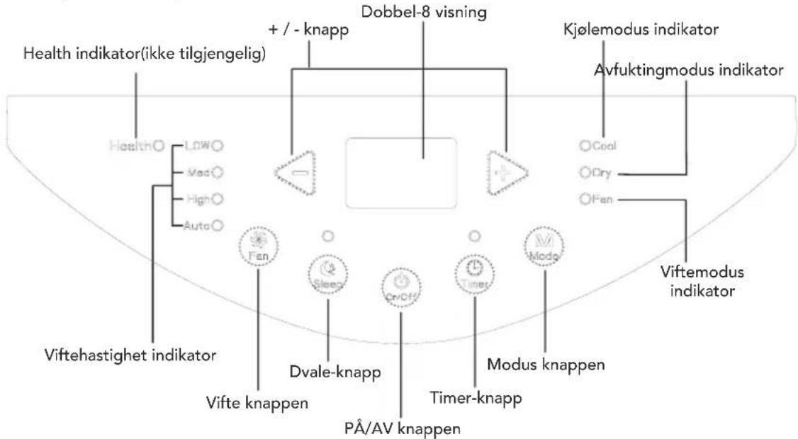
4. FAN button
5. X-VIFTE (FAN) button
6. DVALE (SLEEP) button
CLEANING AND MAINTENANCE
WARNING:
NOTE:
NOTE:
CAUTION:
INTRODUCTION TO THE CONTROL PANEL
③ Install the filter
NOTE:
REMOVING COLLECTED WATER
KEEP IN MIND:
INSTALLING AND REMOVING THE HEAT OUTLET PIPE
NOTE
OPERATING INSTRUCTIONS CONTROL PANEL
SPEED 2 (▲), SPEED 3 (▲)
![graph LR A["AUTO"] --> B["△"] B --> C["△"] C --> D["△"]](/content/2026/05/872317/images/5bb21e12efb92e416e1afea570ec10ea12a7f7ba74f73b119b5d3983517fe9c3.jpg)
NOTE:
③ Install filter
NOTE:
REMOVAL OF COLLECTED WATER
NOTE:
INSTALLATION AND REMOVAL OF HEAT DISSIPATION TUBE
NOTE:
REMOVING COLLECTED WATER
NOTE:
INSTALLING AND REMOVING THE HEAT DISSIPATION TUBE
Operation Environment 4
Parts description 5
Use for air conditioner 6
Operation Introduction for Control Panel 7
Buttons on Remote Controller 8
Introduction for Icons on Display Screen 9
Introduction for Buttons on Remote Controller 9
Function Introduction for Combination Buttons 11
Operation Guide 11
Replacement of Batteries in Remote Controller 11
Clean and Maintenance 12
Malfunction Analysis 14
Installation Precaution 17
Preparation before Installation 19
Install Wire Hook 20
Removing Collected Water 21
Installation and Disassembly of Heat Discharge Pipe 24
Electric Schematic Diagram 27
SAFETY INSTRUCTIONS
- Aside from cleaning, all service should be carried out by an authorized service center. Only authorized service personnel should carry out repair work.
- This appliance can be used by children aged from 8 years and above and persons with reduced physical, sensory or mental capabilities or lack of experience and knowledge if they have been given supervision or instruction concerning use of the appliance in a safe way and if they understand the hazards involved. Children shall not play with the appliance. Cleaning and user maintenance shall not be made by children without supervision.
- If the supply cord is damaged, it must be replaced by the manufacturer, its service agent or similarly qualified persons in order to avoid a hazard.
Explanation of Symbols
 | DANGER | Indicates a hazardous situation that, if not avoided, will result in death or serious injury. |
 | WARNING | Indicates a hazardous situation that, if not avoided, could result in death or serious injury. |
 | CAUTION | Indicates a hazardous situation that, if not avoided, may result in minor or moderate injury. |
 | NOTICE | Indicates important but not hazard-related information, used to indicate risk of property damage. |
 | Indicates a hazard that would be assigned a signal word WARNING or CAUTION. | |
- The air conditioner must be operated within the temperature range: 16°C ~ 35°C.
- The appliance is for indoor use only.
- The appliance must be positioned so that the plug is accessible.
- This air conditioner is for domestic, non-commercial use only.
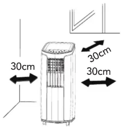
- Reserved space around the air conditioner should be at least 30 cm.
- Do not operate the air conditioner in a humid environment.
- Please keep the air inlet and air outlet clean and free of obstacles.
- During operation, close doors and windows to improve the cooling effect.
- Please place the air conditioner on a smooth and flat surface to avoid noise and vibration.
- This air conditioner is equipped with castors. Castors should slide on a smooth and flat surface.
- Prohibit inclining or turning over the air conditioner. If there is any abnormality, please disconnect the power immediately and contact the dealer.
- Avoid direct sunshine.
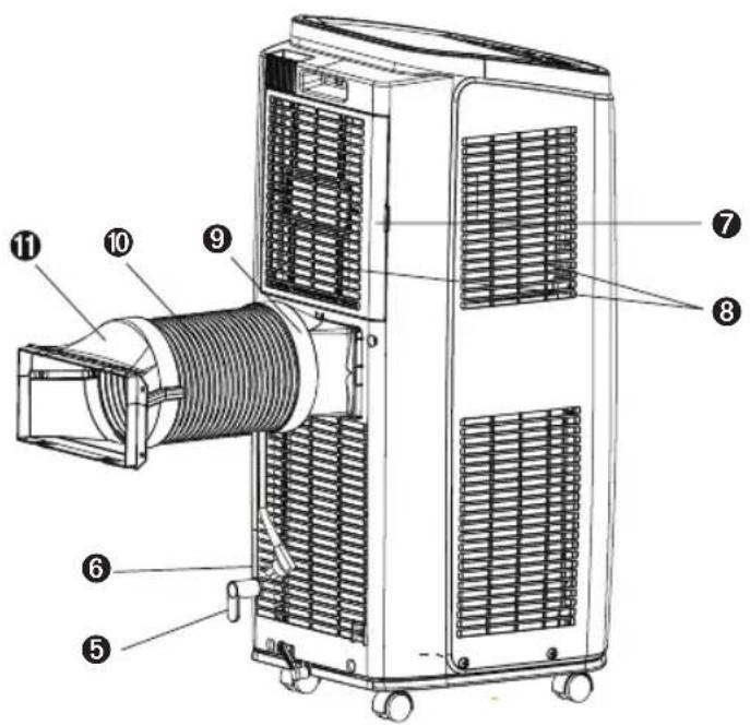
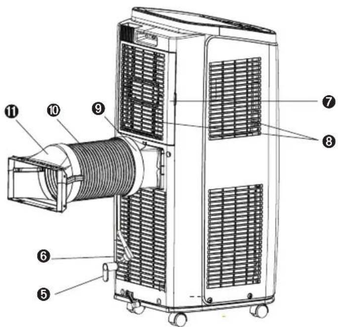
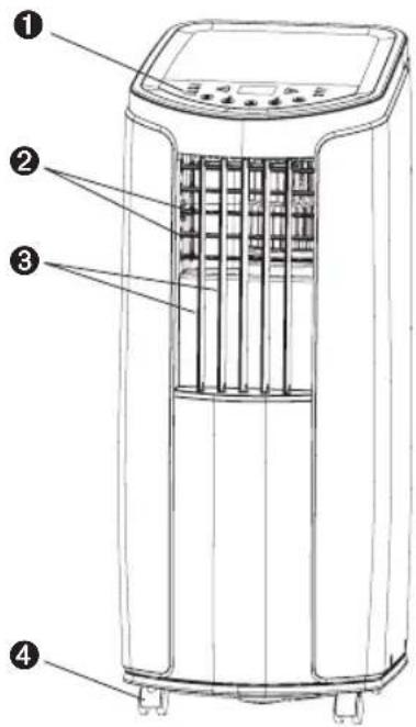
PARTS·DESCRIPTION
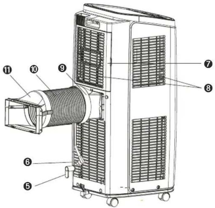
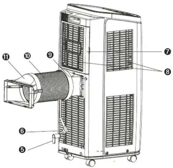
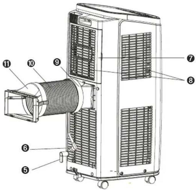
① Controller panel ② Guide louver ③ Swing louver ④ Castor ⑤ Wire-fixing hook ⑥ Plug of power cord ⑦ Filter ⑧ Air inlet ⑨ Joint A ⑩ Heat discharge pipe ⑪ Joint B+C
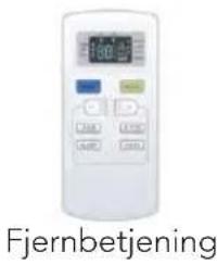
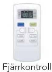
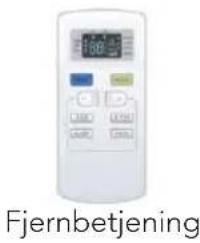
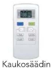
Remote controller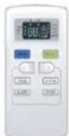
NOTICE:
Heat discharge pipe and other installation accessories can't be discarded.
USE FOR AIR CONDITIONER
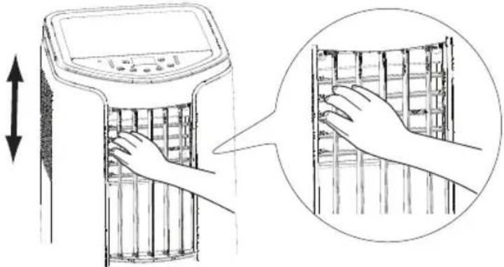
To change air flow direction
- Up/down air flow direction
- Hold the horizontal louvers as shown in the diagram and adjust the air flow direction.
- Do not adjust the horizontal louvers to the lowest or the highest position in the COOL or DRY mode with the fan speed set to Low for an extended period of time, Condensation may form on the louvers.
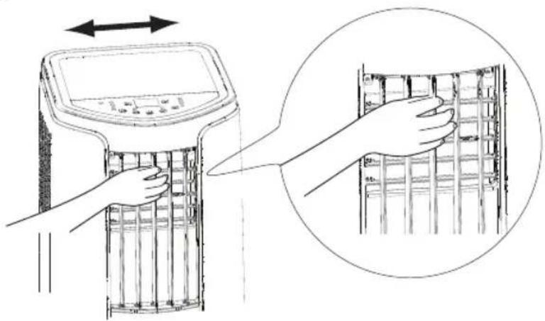
- Left/right air flow direction. Hold the vertical louver as shown in the diagram and adjust the air flow direction.
CAUTION:
- Do not adjust the vertical louvers to the extreme left or right in the COOL or DRY mode with the fan speed set to Low for an extended period of time. Condensation may form on the louvers.
Name of control panel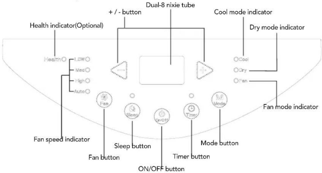
Operation of control panel
NOTICE:
• After connecting the air conditioner to the power supply, it will sound a beep. After that, you can operate the air conditioner by the control panel. - Under ON status, after each pressing of the button on the control panel, the air conditioner will give out a sound. Meanwhile, the corresponding indicator on the control panel will be bright. - Under OFF status, the dual-8 nixie tube on the control panel won't display. Under ON status, the dual-8 nixie tube on the control panel will display the set temperature. Under another mode, it won't display.
1. ON/OFF button
Pressing this button will turn on or turn off the air conditioner.
2. + / - button
Under cooling mode, press "+" or "-" button to increase or decrease the temperature by 1°C (°F). Set temperature range is 16°C~30°C. Under drying or fan mode, this button is invalid.
3. Mode button
Press this button and the mode will circulate according to the following sequence: COOL→DRY→FAN
- COOL: Under this mode, the cooling mode indicator is bright. The dual-8 nixie tube displays the set temperature. Temperature setting range is 16°C~30°C.
- DRY: Under this mode, the drying mode indicator is bright. The dual-8 nixie tube won't display.
- FAN: Under this mode, the air conditioner only blows fan. The fan indicator is bright. The dual-8 nixie tube won't display.
4. Fan button
Press this button and the fan speed will cycle as "low speed → medium speed → high speed → auto fan → low speed".
5. Timer
Press the timer button to enter timer setting mode. In this mode, press the "+" or "-" button to adjust the timer setting. The timer setting will increase or decrease by 0.5 hours when pressing "+" or "-" within 10 hours, and by 1 hour when pressing "+" or "-" beyond 10 hours. After the timer setting is finished, the unit will display the temperature if there is no operation for 5 seconds. If the timer function is activated, the upper indicator will remain lit. Otherwise, it will not be displayed. In timer mode, press the timer button again to cancel timer mode.
6. Sleep
Press the sleep button to enter sleep mode. If the controller operates in cooling mode, after sleep mode is activated, the preset temperature will increase by 1°C within 1 hour; the preset temperature will increase by 2°C within 2 hours, and then the unit will operate at this temperature continuously. Sleep function is not available in fan mode and drying mode. If sleep function is activated, the upper indicator will remain lit.
BUTTONS ON REMOTE CONTROLLER
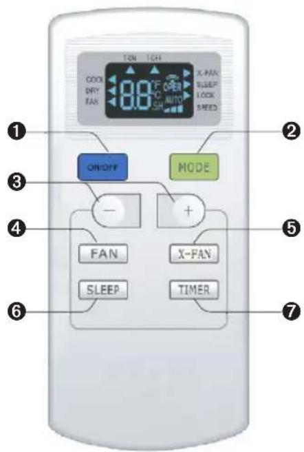
① ON/OFF button ② MODE button ③ +/- button ④ FAN button ⑤ X-FAN button ⑥ SLEEP button ⑦ TIMER button
INTRODUCTION FOR ICONS ON DISPLAY SCREEN
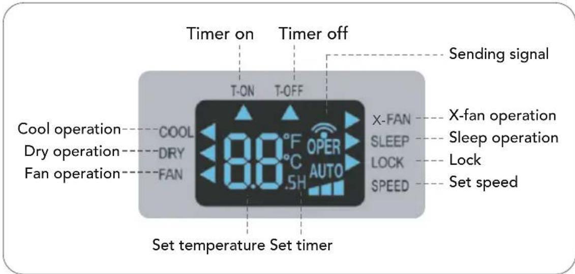
INTRODUCTION FOR BUTTONS ON REMOTE CONTROLLER
Note:
- This is a general use remote controller; it can be used for air conditioners with multiple functions. For functions that the model does not have, pressing the corresponding button on the remote controller will keep the unit in its original running status.
- After connecting the air conditioner to the power supply, the unit will emit a sound. The operation indicator "1" is ON (red indicator). After that, you can operate the air conditioner using the remote controller.
- Under ON status, pressing a button on the remote controller will cause the signal icon on the remote controller's display to blink once, and the air conditioner will emit a "de" sound, indicating that the signal has been sent to the air conditioner.
- Under OFF status, the set temperature and clock icon will be displayed on the remote controller's display (if timer on, timer off, and light functions are set, the corresponding icons will also be displayed). Under ON status, the display will show the corresponding set function icons.
1. ON/OFF button
Press this button to turn unit ON/OFF.
2. MODE button
Pressing this button once will select your required mode circularly as below (the corresponding icon "◀" will be lit up after the mode is selected):
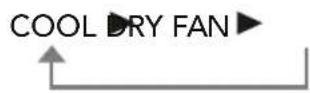
- When selecting cool mode, air conditioner will operate under cool mode. Then press + or - button to adjust set temperature. Press FAN button to adjust fan speed.
- When selecting dry mode, air conditioner will operate at low fan speed. In dry mode, fan speed can't be adjusted.
- When selecting fan mode, air conditioner will operate in fan mode only. Then press FAN button to adjust fan speed.
3. + / - button
- Pressing + or - button once will increase or decrease set temperature by 1°C (°F). Holding + or - button for 2s, set temperature on remote controller will change quickly. Release the button after your required set temperature is reached.
- When setting Timer On or Timer Off, press + or - button to adjust the time. (See TIMER Button for setting details)
4. FAN button
Pressing this button can select fan speed circularly as: AUTO, SPEED 1 ( ). SPEED 2 ( ). SPEED 3 ( ).
![graph LR A["AUTO"] --> B["△"] B --> C["△"] C --> D["△"]](/content/2026/05/872317/images/61f32e9f441f04f2e9faf1a8a1f801d88c4e3e7c2d2fc94ec0d9d5cb1b45a7ce.jpg)
Note:
- Under Auto speed, air conditioner will select proper fan speed automatically according to ambient temperature.
- Fan speed can't be adjusted under Dry mode.
5. X-FAN button
Press this button under cool and dry mode to start up x-fan function. Press this button again to cancel x-fan function.
Note:
- When x-fan function is on, if the air conditioner is turned off, indoor fan will still operate at low speed for a while to blow the residual water inside the air duct.
- During x-fan operation, press X-FAN button to turn off x-fan function. Indoor fan will stop operation immediately.
6. SLEEP button
Under Cool and Dry mode, press this button to turn on Sleep function. Press this button to cancel Sleep function. Under Fan mode, this function is unavailable.
7. TIMER button
- When unit is on, press this button to set Timer Off. T-OFF and H icon will be blinking. Within 5s, press + or - button to adjust the time for Timer Off. Pressing + or - button once will increase or decrease the time by 0.5h. Holding + or - button for 2s, time will change quickly. Release the button after your required set time is reached. Then press TIMER button to confirm it. T-OFF and H icon will stop blinking.
- When unit is off, press this button to set Timer On. T-ON and H icon will be blinking. Within 5s, press + or - button to adjust the time for Timer On. Pressing + or - button once will increase or decrease the time by 0.5h. Holding + or - button for 2s, time will change quickly. Release the button after your required set time is reached. Then press TIMER button to confirm it. T-ON and H icon will stop blinking.
- Cancel Timer On/Off: If Timer function is set up, press TIMER button once to review the remaining time. Within 5s, press TIMER button again to cancel this function.
Note:
- Timer setting range: 0.5~24h
- The interval between two motions can't exceed 5s, otherwise the remote controller will exit setting status.
FUNCTION INTRODUCTION FOR COMBINATION BUTTONS
Child lock function
Pressing "+" and "-" buttons simultaneously will turn "ON" or turn "OFF" child lock function. When child lock function is started up, LOCK indicator on remote controller is ON. If you operate the remote controller, remote controller won't send signal.
Temperature display switchover function
Under OFF status, pressing "-" button and "MODE" button simultaneously can switch between °C and °F.
OPERATION GUIDE
- After putting through the power, press "ON/OFF" button on remote controller to turn on the air conditioner.
- Press "MODE" button to select your required mode: COOL, DRY, FAN.
- Press "+" or "-" button to set your required temperature.
- Press "FAN" button to set your required fan speed: auto, low, medium and high speed.
REPLACEMENT OF BATTERIES IN REMOTE CONTROLLER
- Press the back side of remote controller on the spot marked with "”, and then push out the cover of battery box along the arrow direction.
- Replace two (AAA 1.5V) dry batteries and make sure the positions of + and - polar are correct.
- Reinstall the cover of battery box.
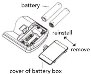
NOTICE:
- During operation, point the remote control signal sender at the receiving window on unit.
- The distance between signal sender and receiving window should be no more than 8m, and there should be no obstacles between them.
- Signal may be easily interfered with in rooms with fluorescent lamps or wireless telephones; the remote controller should be close to the unit during operation.
- Replace with new batteries of the same model when replacement is required.
- If you do not use the remote controller for a long time, please take out the batteries.
- If the display on the remote controller is fuzzy or there is no display, please replace the batteries.
CLEANING AND MAINTENANCE
WARNING:
- Before cleaning the air conditioner, turn off the unit and disconnect the power. Otherwise, it may cause electric shock.
- Do not wash the air conditioner with water. Otherwise, it may cause electric shock.
- Do not use volatile liquids (such as thinner or gas) to clean the air conditioner. Otherwise, it may damage the appearance of the air conditioner.
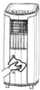
Clean the outer case and grille
Clean the outer case: If there is dust on the surface of the outer case, use a soft towel to wipe it. If the outer case is very dirty (such as with grease), use a neutral detergent to wipe it.
Clean the grille: Use a cleaner or soft brush to clean it.
Clean the filter
① Remove the filter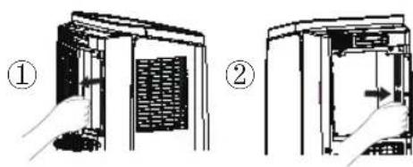
③ Install the filter
After the filter is cleaned and dried, reinstall it well.
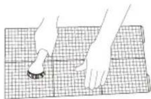
② Clean filter
Use cleaner or water to clean the filter. If the filter is very dirty (such as grease), use warm water 40°C (104°F) mixed with neutral detergent to clean it and then put at shady place to dry it.
NOTICE:
- The filter should be cleaned about once every three months. If there's much dust in the operation environment, you can increase clean frequency.
- Do not dry the filter with fire or hair drier. Otherwise, it may be deformed or catch fire.
Clean heat discharge pipe
Remove the heat discharge pipe from air conditioner, clean and dry it, and then reinstall it. (For the method of installation and removal, please refer to the instruction for "Installation and disassembly of heat discharge pipe" on page 25).
Checking before use-season
- Check whether air inlets and air outlets are blocked.
- Check whether plug and socket are in good condition.
- Check whether filter is clean.
- Check whether batteries are installed in remote controller.
- Check whether joint, window bracket and heat discharge pipe are installed tightly.
- Check whether heat discharge pipe is damaged.
Checking after use-season
- Disconnect power supply.
- Clean filter and outer case.
- Remove dust and other impurities from the air conditioner.
- Eliminate accumulated water in chassis (refer to the section of "Drainage way" for details).
- Check whether window bracket is damaged or not. If yes, please contact dealer.
Long-time storage
If you don't use the air conditioner for a long time, please maintain it by following steps for good performance:
- Make sure there's no accumulated water in chassis and that the heat discharge pipe is disassembled.
- Pull out the plug and wrap the power cord.
- Clean the air conditioner and pack it well to prevent dust.
Notice for recovery
- Parts of gift packaging is recycled. Users are advised to follow local regulations or take contact with personell at the local recycling center for further guidance.
- If you want to throw away the air conditioner, please contact local division or consultant service center for the correct disposal method.
MALFUNCTION ANALYSIS
Please check the items below before requesting maintenance. If the malfunction still cannot be eliminated, please contact your local dealer or qualified professionals.
| Phenomenon Troubleshooting Solution | ||
| Air conditioner can't operate | Power failure? | Wait after power recovery. |
| Connected to power? Reinsert the plug. | ||
| Has the air switch tripped off or has the fuse been blown? | Ask for professional help to replace air switch or fuse. | |
| Is there's malfunction for the circuit? | Ask for professional help to replace circuit. | |
| Has the unit been restarted immediately after a stopp? | Wait for 3min, and then try turning it on again. | |
| Poor cooling (heating) | Is the power too low? | Make sure that the device has been connected to a proper power source |
| Is the air filter filled with dust/impurities? | Clean the air filter. | |
| Has the temperature for the unit been set properly? | Adjust the temperature. | |
| Are doors and windows closed? | Close door and window. | |
| Air conditioner can't receive signal from remote controller or remote controller is not sensible. | Is normal operation interrupted by events such as static pressure, unstable voltage? | Please pull out the plug. Insert the plug after about 3min, and then turn on the unit. |
| Is the remote controller within the receiving range? | The receiving range of remote controller is 8m. Do not exceed this range. | |
| Does any physical obstacles block free sight between remote and unit? | Remove the obstacles. | |
| Is sensitivity of remote controller low? | Check the batteries of remote controller. If the power is low, please replace the batteries. | |
| Is there a fluorescence lamp in the room? | Move the remote controller close to air conditioner. Turn off the fluorescence lamp and try it again. | |
| No fan blown out from air conditioner | • Is the air outlet or air inlet blocked? | • Eliminate the obstacles. |
| • Is the air filter unclean? • Clean air filter | ||
| Set temperature can't be adjusted. | • Has the unit been set to operate at auto mod or has child lock been activated? | • Temperature can't be adjusted under auto mode. Child lock can be unlocked by pressing "+" and "-" |
| • Is the room temperature within the temperature range for the unit? | • Temperature setting range: 16°C-30°C. | |
| There's off flavour | • There's off-flavour source in the room, such as furniture, cigarette etc. | • Eliminate the off-flavour source.• Clean the filter. |
| There's abnormal sound during operation | • Whether the unit is interfered by thunder, radio, etc? | • Disconnect power, put through the power again, and then turn on the unit again. |
| You can heard water-flowing sound | • Hearing a sound right after turning on or off? | • There's flowing sound of refrigerant inside the air conditioner, which is the normal phenomenon. |
| You can heard the sound of "brekage" | • Hearing a sound right after turning on or off? | • Heat expansion or shrinkage for the panel due to change of temperature, which cause friction sound. |
Malfunction code
| E5 Overcurrent protection. Disconnect power, and then turn on the unit again after 10min. If "E5" still exits, please contact professional person to maintain the unit. | |
| H8 Chassis is full of water. 1. Pour out the water inside chassis.2. If "H8" still exits, please contact professional person to maintain the unit. | |
| F1 Malfunction of ambient temperature sensor. | Please contact professional person to deal with it. |
| F2 M | Malfunction of evaporator temperature sensor. | Please contact professional person to deal with it. |
| F0 1. | Refrigerant is leaking2. System is blocked | 1. Re-energize the unit after turning off and pulling out the plug for 30min;2. If there's still malfunction, please contact after-sales service. |
| H3 O | Overload protection for compressor | 1. Check if the unit is under high-temperature and high-humidity environment; if ambient temperature is too high, power off the unit and then energize it for operation after the ambient temperature drops to 35°C below.2. Check if the evaporator and condenser are blocked by some objects; if yes, take away the objects, power off the unit and then energize it for operation.3. If the malfunction still occur, please contact our after-sales service center. |
| E8 O | Overload malfunction | |
| F4 O | Outdoor tube temperature sensor is open/short-circuited. | Please contact after-sale service person to deal with it. |
WARNING:
- If any of the following phenomena occur, turn off the air conditioner and disconnect the power immediately, then contact your dealer immediately.
– Power cord is overheating or damaged.
- Abnormal sound during operation.
- Off-flavor.
- Water leakage.
- Do not repair or modify the air conditioner yourself.
- If the air conditioner is operated under abnormal conditions, it may cause malfunction, electric shock, or fire hazard.
INSTALLATION PRECAUTION
Warning:
- Observe all governing codes and ordinances.
- Do not use a damaged or non-standard power cord.
- Be careful during installation and maintenance. Prohibit incorrect operation to prevent electric shock, casualty, and other accidents.
Selection of installation location
Basic requirement
Installing the unit in the following places may cause malfunction. If it is unavoidable, please consult the local dealer:
- The place with strong heat sources, vapors, flammable or explosive gas, or volatile objects spread in the air.
- The place with high-frequency devices (such as welding machine, medical equipment).
- The place near coast area.
- The place with oil or fumes in the air.
- The place with sulfureted gas.
- Other places with special circumstances.
Requirement of air conditioner
- Air inlet should be far away from obstacles and do not put any objects near air outlet. Otherwise, it will affect the radiation of heat discharge pipe.
- Please try your best to keep far away from fluorescent lamp.
- The appliance shall not be installed in the laundry. High humidity can cause malfunction.
Requirements for electric connection
Safety precaution
- Must follow the electric safety regulations when installing the unit.
- According to the local safety regulations, use qualified power supply circuit.
- If the supply cord is damaged, it must be replaced by the manufacturer, its service agent or similarly qualified persons in order to avoid a hazard.
- Properly connect the live wire, neutral wire and grounding wire of power socket.
- Be sure to cut off the power supply before proceeding any work related to electricity and safety.
- Do not put through the power before finishing installation.
- The air conditioner is first class electric appliance. It must be properly grounding with specialized grounding device by a professional. Please make sure it is always grounded effectively, otherwise it may cause electric shock.
- The grounding resistance should comply with national electric safety regulations.
- The appliance shall be installed in accordance with national wiring regulations.
PREPARATION BEFORE INSTALLATION
Note: check if the accessories are available before installation.
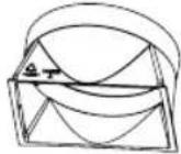
Accessory list
 joint A joint A | 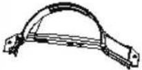 joint B joint joint B joint | 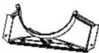 C C | 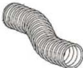 heat discharge pipe heat discharge pipe | 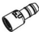 Adapter (1) Adapter (1) | |||
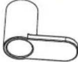 wire hook (2) screw (3) pipe clip wire hook (2) screw (3) pipe clip |  rubber plug pipe hoop (2) rubber plug pipe hoop (2) |  | 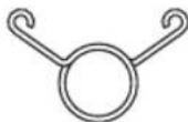 | ||||
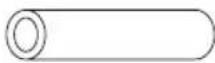 | 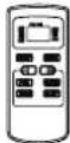 |  battery (2)(AAA 1.5V) battery (2)(AAA 1.5V) |  user's manualrem user's manualrem | ||||
Tools needed for installation
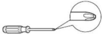 cross screwdriver cross screwdriver |  straight screwdriver straight screwdriver | 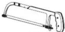 saw saw |
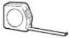 gauge gauge | 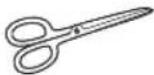 scissors scissors | 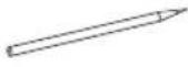 pencil pencil |
INSTALL WIRE HOOK
- Assemble the wire hook at the back of the unit with screws (the direction of wire hook is as shown in following fig).
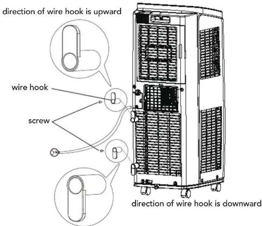
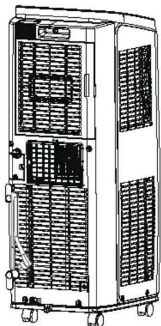
• Wind the power cord around the wire hook.
REMOVING COLLECTED WATER
There are 2 ways to remove collected water:
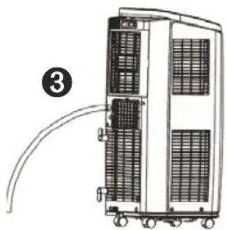
① Use drainage option from the bottom hole.
Note: When using drainage option from the bottom hole, install drainage pipe before using, otherwise poor drainage will affect normal operation of the unit.
Instructions for drainage pipe installation as follows:
- Remove the rubber plug at drainage port.
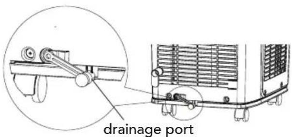
- Fix the drainage pipe clip on the right of rear side plate near drainage port with a screw.
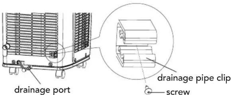
- Put the drainage pipe into drainage port and screw it up, and then bind it with pipe hoop.
- Put the rubber plug into the other side of drainage pipe, fix it with pipe hoop and then fix it in the drainage pipe clip.
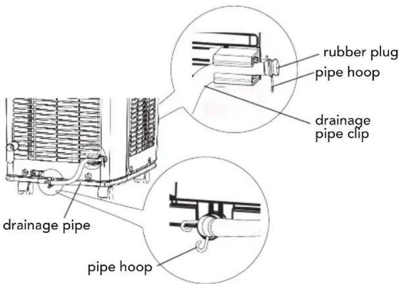
Drainage way as follows:
- In cooling or drying operation, the condensation water will be drained to the chassis and spattered by water-striking motor. As the temperature of condenser is high, most of the condensation water will be evaporated and drained to outdoor. So usually, only a little condensation water will be accumulated inside
the chassis and you do not need to discharge the water frequently.
- When the chassis is full with water, the buzzer will give out 8 sounds and "H8" is displayed to remind user to discharge water:
- Move the unit to a suitable place for emptying of water; do not tilt the unit and keep it horizontal during moving;
- Take the drainage pipe from the clip and pull out the rubber plug on the drainage pipe to empty the water;
- Put back the rubber plug onto drainage pipe after finishing emptying water and then fix the pipe on the clip;
- After full water protection is eliminated and the compressor has been stopped for 3 minutes, the unit will resume operation.
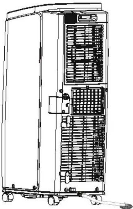
② Use the continuous drainage option from the middle hole.
Note: Water can be automatically emptied into a floor drain by attaching 14mm inner diameter hose (not included).
- Remove the continuous drain cap 1 by turning it counter clockwise then remove the rubber stopper 2 from the spout.
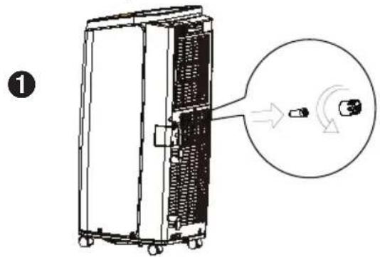
- Screw the drain connector (included in the package) to the spout by turning clockwise.
- Insert the drainage hose into drain connector.
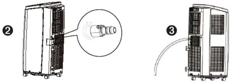
ATTENTION:
When using continuous drainage option from the middle hole, place portable on a level surface and make sure garden hose is clear of any obstructions and is directed downward. Placing portable on an uneven surface or improper hose installation may result in water filling up the chassis and causing the unit to shut off. Empty water in the chassis if shut off occurs, then check portable location and hose for proper setup.
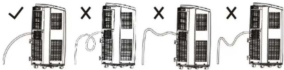
INSTALLATION AND DISASSEMBLY OF HEAT DISCHARGE PIPE
Install heat discharge pipe
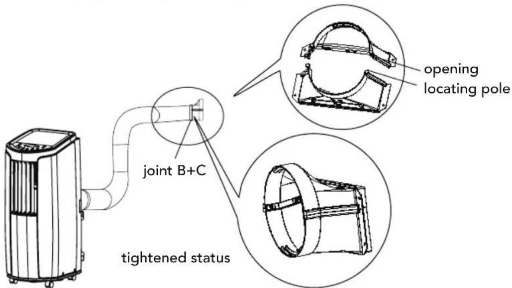
- Rotate joint A and joint B clockwise into the two ends of heat discharge pipe.
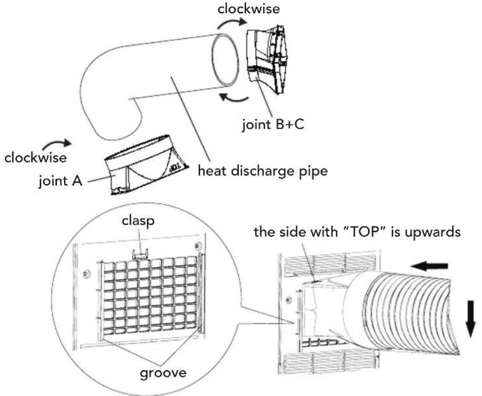
- Insert joint A of heat discharge pipe (the side with "TOP" is upwards) into the groove until you hear a "klikk" sound.
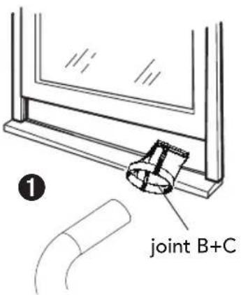
- Aim the locating pole of joint B of heat discharge pipe at the opening of joint C; rotate it slightly to make joint B and joint C connect tightly.
Note of Installing heat discharge pipe
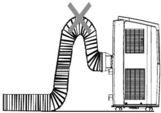
In order to improve cooling efficiency, the heat discharge pipe should be as short as possible and flat without curve to ensure smooth heat discharge.
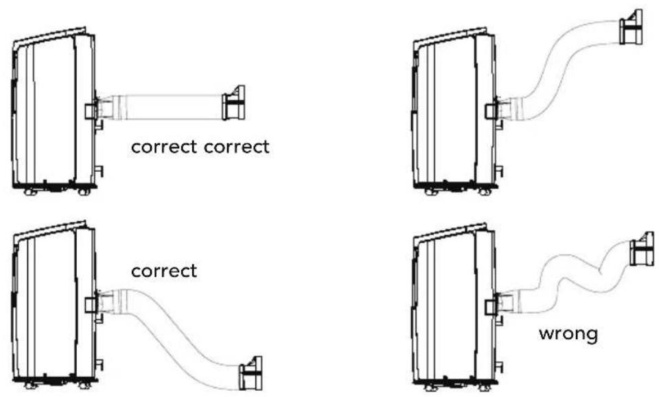
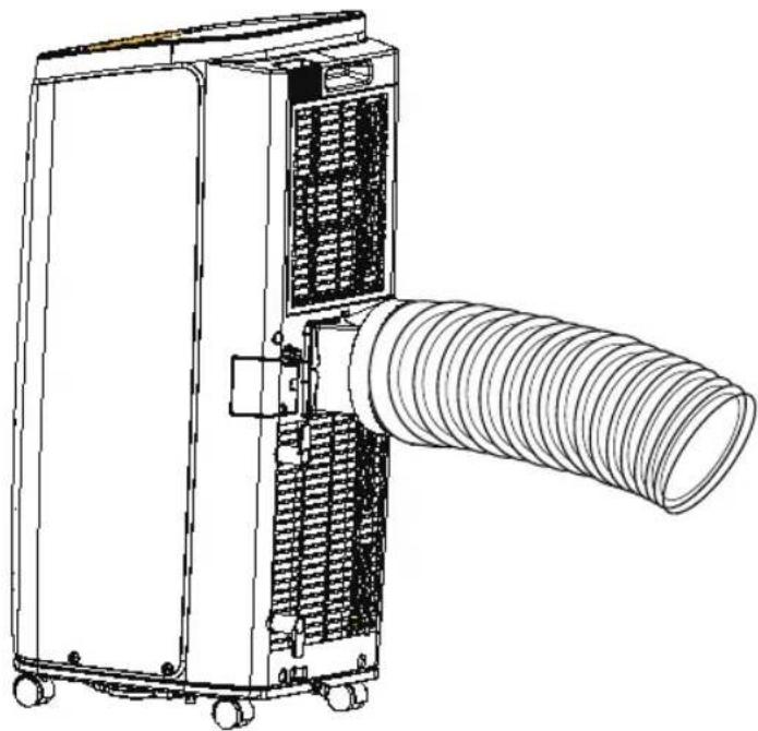
- The length of the heat discharge pipe is less than 1m. It is recommended to use it with shortest length.
- When installing, heat discharge pipe should be as flat as possible. Don't prolong the pipe or connect it with other heat discharge pipe.
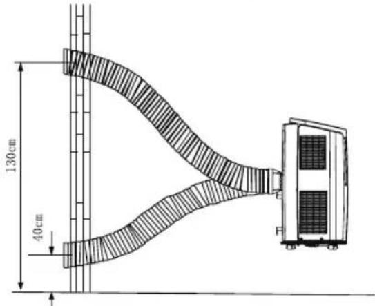
- Correct installation is as shown in figure (When installing it on wall, height of hall should be about 40cm-130cm from floor).
- Wrong installation is shown in following figure (If the pipe is bent too much, it would easily cause malfunction.)
Disassemble heat discharge pipe
- Remove joint B: remove joint B from joint C.
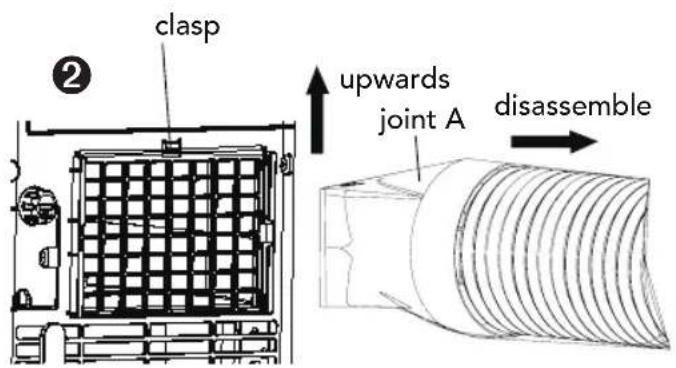
- Remove joint A: Press the clasp and lift joint A upwards to remove it.
ELECTRIC SCHEMATIC DIAGRAM
Cool 7![graph TD A["AP1 MAIN BOARD"] --> B["WATER MOTOR"] A --> C["DISP2"] A --> D["DISP1"] A --> E["AP2"] A --> F["DISPLAY BOARD"] B --> G["ROOM TEMP. SENSOR"] B --> H["RT1 PE"] B --> I["TUBE TEMP. SENSOR"] B --> J["OUTTUBE TEMP. SENSOR"] B --> K["RECEIVER BOARD"] C --> L["DISP2"] C --> M["DISP1"] C --> N[…](/content/2026/05/872317/images/ba3edf5d5c971189b462ae7f23941369152623f4fa391d4d15af9f17509f2639.jpg)
Cool 12![graph TD A["AP1 MAIN BOARD"] --> B["DISPLAY BOARD"] B --> C["AP2 DISP2"] B --> D["DISP1"] C --> E["M3"] D --> F["WATER MOTOR"] E --> G["R00M"] F --> H["R00M"] G --> I["TUBE"] H --> J["TUBE"] I --> K["OUTUBE"] J --> L["OUTUBE"] K --> M["RECEIVER BOARD"] L --> N["REC"] M --> O["COLD PLASMA GENERATOR"]…](/content/2026/05/872317/images/67786dc792c2200dea4f79bfd3a9cffe57066ffc019a0da424e5660eb457c4c2.jpg)
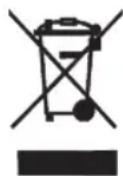
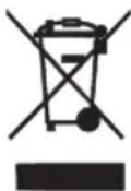
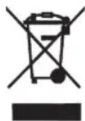
This marking indicates that this product should not be disposed with other household wastes throughout the EU. To prevent possible harm to the environment or human health from uncontrolled waste disposal, recycle it responsibly to promote the sustainable reuse of material resources. To return your used device, please use the return and collection systems or contact the retailer where the product was purchased. They can take this product for environmental safe recycling.
R410A(R32/125: 50/50): 2087.5
Under the Waste Electrical and Electronic Equipment Directive (WEEE), such waste must be collected separately and processed. If in future you need to discard this product, please do not throw it out with your normal rubbish. Please send this product to a collection point where one is available.

in homes since 1948
AS WILFA
Industriveien 25
1481 Hagan
Norway
wilfa.com

- WILFA
- NOTE
- OPERATING INTRODUCTION FOR CONTROL PANEL
- FAN BUTTON
- X-VIFTE (FAN) BUTTON
- DVALE (SLEEP) BUTTON
- CLEANING AND MAINTENANCE
- WARNING
- CAUTION
- INTRODUCTION TO THE CONTROL PANEL
- ③ INSTALL THE FILTER
- REMOVING COLLECTED WATER
- KEEP IN MIND
- INSTALLING AND REMOVING THE HEAT OUTLET PIPE
- OPERATING INSTRUCTIONS CONTROL PANEL
- REMOVAL OF COLLECTED WATER
- INSTALLATION AND REMOVAL OF HEAT DISSIPATION TUBE
- INSTALLING AND REMOVING THE HEAT DISSIPATION TUBE
- SAFETY INSTRUCTIONS
- PARTS·DESCRIPTION
- NOTICE
- USE FOR AIR CONDITIONER
- TO CHANGE AIR FLOW DIRECTION
- OPERATION OF CONTROL PANEL
- ON/OFF BUTTON
- BUTTON
- MODE BUTTON
- TIMER
- SLEEP
- BUTTONS ON REMOTE CONTROLLER
- INTRODUCTION FOR ICONS ON DISPLAY SCREEN
- INTRODUCTION FOR BUTTONS ON REMOTE CONTROLLER
- X-FAN BUTTON
- SLEEP BUTTON
- TIMER BUTTON
- FUNCTION INTRODUCTION FOR COMBINATION BUTTONS
- CHILD LOCK FUNCTION
- TEMPERATURE DISPLAY SWITCHOVER FUNCTION
- OPERATION GUIDE
- REPLACEMENT OF BATTERIES IN REMOTE CONTROLLER
- CLEAN THE OUTER CASE AND GRILLE
- CLEAN THE FILTER
- ② CLEAN FILTER
- CLEAN HEAT DISCHARGE PIPE
- CHECKING BEFORE USE-SEASON
- CHECKING AFTER USE-SEASON
- LONG-TIME STORAGE
- NOTICE FOR RECOVERY
- MALFUNCTION ANALYSIS
- INSTALLATION PRECAUTION
- SELECTION OF INSTALLATION LOCATION
- BASIC REQUIREMENT
- REQUIREMENT OF AIR CONDITIONER
- REQUIREMENTS FOR ELECTRIC CONNECTION
- SAFETY PRECAUTION
- PREPARATION BEFORE INSTALLATION
- INSTALL WIRE HOOK
- ① USE DRAINAGE OPTION FROM THE BOTTOM HOLE
- ② USE THE CONTINUOUS DRAINAGE OPTION FROM THE MIDDLE HOLE
- ATTENTION
- INSTALLATION AND DISASSEMBLY OF HEAT DISCHARGE PIPE
- INSTALL HEAT DISCHARGE PIPE
- NOTE OF INSTALLING HEAT DISCHARGE PIPE
- DISASSEMBLE HEAT DISCHARGE PIPE
- ELECTRIC SCHEMATIC DIAGRAM
Brand : WILFA
Model : Cool 7
Category : Air conditioner