
3121V - Car alarm Viper - Free user manual and instructions
Find the device manual for free 3121V Viper in PDF.


| Brand | Viper |
| Model | 3121V |
| Product Type | Car Alarm / Powersports Security System |
| Power Supply | 12V DC (vehicle battery) |
| Current Draw | Negligible in sleep mode; < 10 mA in normal operation |
| Remote Battery | 1 x CR2032 3V coin cell |
| Remote Range | Up to 200 feet (typical) |
| Number of Remotes Supported | Up to 4 |
| Siren Output | Positive (default) or negative (programmable) |
| Parking Light Output | Configurable to positive or negative |
| Starter Disable | Integrated (cut wires) |
| Auxiliary Output | 200 mA negative, programmable momentary or latched |
| Sensors | Tilt sensor and shock sensor (sensitivity adjustable) |
| Alarm Zones | Ignition, tilt/shock, instant, closed loop |
| Operating Modes | Arm, disarm, panic, anti-jacking, valet, auto re-arm |
| Sleep Mode | Enabled after 96 hours of inactivity to save battery |
| Memory Function | Non-volatile: retains last status (armed, valet, etc.) |
| Emergency Override | Via ignition cycle + PIN code (factory default PIN=1) |
| FCC Compliance | Part 15, Class B digital device |
| Warranty | Limited lifetime on control module; 1 year on accessories |
| Maintenance | Replace remote battery as needed; no other regular maintenance |
| Sleep Mode Wake | Cycle ignition to wake unit |
Frequently Asked Questions - 3121V Viper
User questions about 3121V Viper
0 question about this device. Answer the ones you know or ask your own.
Ask a new question about this device
Download the instructions for your Car alarm in PDF format for free! Find your manual 3121V - Viper and take your electronic device back in hand. On this page are published all the documents necessary for the use of your device. 3121V by Viper.
USER MANUAL 3121V Viper
The company behind Viper ^® Auto Security Systems is Directed.
Since its inception, Directed has had one purpose, to provide consumers with the finest vehicle security and accessories available. The recipient of nearly 100 patents and Innovations Awards in the field of advanced electronic technology.
Quality Directed products are sold and serviced throughout North America and around the world.
Call (800) 876-0800 for more information about our products and services.
© 2017 Directed. All rights reserved.
500-13745 (B1.0)
VIPER®
NO ONE DARES COME CLOSE

natural_image
Illustration of a snake's head with open mouth and large eyes, set against a yellow background (no text or symbols)Vista, CA 92081 www.directed.com
Directed is committed to delivering world class quality products and services that excite and delight our customers.
OWNER'S GUIDE & INSTALL GUIDE
MODEL 3121V
Table of Contents
Congratulations ....1
Standard Remote Configuration 2
2-Button Transmitter 2
Remote Learning 2
Arming....3
Disarming 4
Aux....5
Auto Re-Arming 5
Panic....5
Anti Motorcycle-Jacking 6
Emergency Override 6
Pin Number Setting 7
Valet Mode 7
Memory Function......8
Feature Settings 8
Power Saving (Sleep) Mode....11
System Maintenance....12
Battery Replacement....12
Battery Disposal 12
Installation Guide....13
Government Regulations 17
Limited Lifetime Consumer Warranty....19
Congratulations
Congratulations on the purchase of your state-of-the-art Power Sports Alarm System. Reading this Installer and Owner's Guide prior to using your system will help maximize the use of its many features. For more information please visit us online (see back cover for URL). For any additional questions please contact your authorized Directed dealer or Directed at 1-800-753-0600. Additional support is also available at: http://support.directed.com.
Note: This system is equipped with a sleep mode to lower current draw. After 96 hours of no activity, the system's sleep mode turns on and RF communication shuts down. If your system is not responding to remotes, you may need to cycle ignition to wake the unit up before remotes will control the system again.
Standard Remote Configuration
| Function Button Action | ||
| Arm | [XAO7] | Press and release |
| Disarm |  | Press and release |
| Panic |  | Press and hold (any system state) |
| Aux Output | 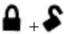 | Press and release (any system state) |
| Tilt bypass |  | Press and release within 5 seconds of arming system |
| All Sensor Bypass | [H49C] | Press and release 2 times within 5 seconds of arming system |
| Anti-Jacking (On & Off) |  | Press and hold (ignition on & system disarmed) |
| Valet mode | [TH0S] | Cycle ignition on & off twice, then press and release |
2-Button Transmitter
Remote Learning
In case the remote is lost, or you want to add another remote (up to 4 max), perform the following procedure:
-
With the system disarmed, turn the ignition ON & OFF 5 times within 15 seconds, and stay in the ON position on the fifth time you turn the ignition ON. 3 seconds later the Siren will chirp 3 times to indicate the system entered remote learning mode.
-
Press any button on the remote. The siren will chirp the number of times corresponding to the sequence of the remote location in the system. For example, the first remote learned
to the system will chirp once, the second two times, and so on, until a total of 4 remotes are learned to the system.
- Up to 4 remotes can be learned to the system. If you want to learn a 5th remote, the 1st remote will be cleared from the system, and when you learn a 6th remote, the 2nd remote will be cleared, and so on.
- To exit learn mode – The system will exit learn mode automatically after 8 seconds or you can manually exit learn mode by turning the ignition OFF. The siren will emit one long chirp to indicate that learn mode has been exited.
Note: If your remote is lost or stolen, you can clear old remotes from the system by simply learning the remaining remotes up to 4 times.
Arming
With the system disarmed and the ignition OFF, press the 🔒 button once. The siren will chirp once, parking lights will flash once, and LED will flash quickly. After 8 seconds, the system will fully arm, and LED will flash slowly and engine will be disabled and all trigger zones will be active.
Ignition Trigger
In armed mode, if the ignition is turned on, the system will be triggered and the siren will sound, and the parking lights will flash 30 seconds. The system will repeat this 30 second-cycle of siren and parking light flashes until the ignition is turned OFF. After the ignition is turned to OFF, the system will complete the current 30 second cycle before the siren and parking lights stop.
Tilt/Shock Sensor Trigger
-
Sensitivity for Tilt/Shock sensors are adjustable, see FUNCTION SELECT MENU 1&2.
-
If the motorcycle is tilted/moved:
- If the system is in Sleep mode: At first, the siren will chirp and parking lights will flash 10 times, then the siren will sound continuously for 30 seconds with parking light flashes.
- If the system is in Wake mode: The siren and parking lights will trigger continuously for 30 seconds.
Note: Any alarm zone can be triggered up to 8 times per arming cycle.
Arming and Bypassing Tilt Sensor
After arming the system, press 🔒 once within 5 seconds. The system will emit one long chirp to indicate that the Tilt sensor is bypassed. In this mode, the LED will flash twice every 2 seconds.
Arming and Bypassing Tilt and Shock Sensor
After arming the system, press 🔒 twice within 5 seconds, The system will emit one long chirp to indicate that the Tilt sensor is bypassed and then will chirp three more times to indicate that shock sensor is also bypassed. In this mode, the LED will flash twice every 2 seconds.
Disarming
In armed mode, press ⚙ once. The siren will chirp twice, the parking lights will flash twice, and the system will be disarmed.
If the alarm was triggered during armed mode, the siren will chirp 4 times when disarming. The parking lights will flash a number of
times to indicate the last zone that was triggered when the system was armed.
Table of Zones
| Parking Light Flash System Triggered Zone | |
| 4 times Tilt/Shock sensor triggered | |
| 5 times Instant triggered | |
| 6 times Loop wire triggered | |
| 7 times Ignition triggered |
Aux
Press and release 🔒 and ⚙. An optional auxiliary function, such as lighting or radio turn on, can be controlled by pressing these buttons. By default, the aux channel sends a 1-second pulse on the aux wire. This can change to a latched output that stays on when the command is sent, and then turns off when the command is sent again.
Auto Re-Arming
Note: This is an optional feature that needs to be turned on. See "Feature Settings" on page 8 for more information.
After disarming and no ignition activity, the system will re-arm after 60 seconds. During the 60 second countdown, the LED will flash quickly. When the system re-arms, the siren will chirp and the parking lights will flash once.
Panic
If you are threatened near your motorcycle, you can attract attention by triggering the system with your transmitter. Just press 📄 for 2 seconds to enter panic mode. The siren will sound for 10
second, and the parking lights will flash for 10 seconds. Press to stop panic.

Anti Motorcycle-Jacking
-
With the ignition ON, press and hold ⚡ for 2 seconds. The LED will flash quickly indicating that motorcycle-jacking mode is activated. The siren will chirp once every 3 seconds. After chirping 5 times, the siren will chirp once every 1.5 second. After chirping 8 times, the siren will sound continuously; the parking lights will continuously flash and the engine will be disabled. (Press and hold ⚡ for 2 seconds to exit motorcycle-jacking mode). During anti motorcycle-jacking mode, the siren will long chirp, when the key turns to OFF, the siren will stop, and the parking lights will stop flashing as long as the ignition turns OFF. If key has been turned to ON again, the siren will sound and engine will not be able to start.
-
To exit anti motorcycle jacking: EMERGENCY OVERRIDE.
Emergency Override
In armed mode or motorcycle-jacking mode, if the remote is not working or lost, refer to following step for Emergency Override:
- Tum the ignition to ON/OFF 5 times within 10 second and stay in ON position on the fifth turn on. The LED will turn solid for 2 seconds.
- Once the LED turns OFF, turn the ignition OFF, and the LED will start flashing.
- Once the LED flashes the number of times corresponding to the digit of your PIN code, turn the ignition ON. The Siren will chirp 4 times, and the parking lights will flash 7 times to indicate the system is disarmed.
Pin Number Setting
Factory Preset Pin Number: 1 (Led Blinks One Time)
In disarming mode, turn ignition ON/OFF 8 times within 15 second, and end in ON position on the eighth time. The LED will stay solid for 2 seconds, then the system enters into PIN setting mode:
1. Confirm the original (preset) PIN Number
Turn the ignition OFF within 10 second, LED will start blinking slowly to confirm the preset PIN Number. Turn the ignition ON once the LED blinks the number of times corresponding to the original preset PIN number. If correct, the siren will chirp once (if siren does not chirp, it means the preset PIN number confirmation failed. Start the process over again if this happens);
2. Input the new PIN NUMBER
Right after the siren chirp once, turn the ignition Off, and the system enters into new PIN number setting, and LED starts to flash. When the LED flashes the number of times wanted for the new PIN number, turn the ignition ON then OFF. The LED will flash the new PIN number once, and then exit PIN NUMBER setting mode.
Exit Pin Number Setting
If no operation is performed or the wrong initial password was entered within 30 seconds, the system will exit PIN NUMBER setting mode.
Valet Mode
You can prevent your security system from automatically arming by using valet mode, this is very useful when washing the motorcycle, for example. In valet mode, the security system will not arm, even with the transmitter, but any accessory functions will continue to work normally.
Enter Valet Mode
Turn the ignition ON and then OFF 2 times, and press and hold 🔒 and ⚡ within 5 seconds. The siren will chirp once, and the system will enter valet mode. In valet mode, the LED will stay on solid for 1 hour, and then will shut off to reduce current draw. In valet mode if you press the 🔒 button, the siren will chirp 3 times. Once the 1-hour solid LED cycle ends, the LED will also flash 3 times when the 🔒 button is pressed.
Note: Use the same method to exit valet mode.
Memory Function
This security system will store its current status to non-volatile memory. If power is lost then reconnected, the system will recall the stored status from memory. This means if the unit is in valet mode and the battery is disconnected for any reason, such as servicing the motorcycle, when the battery is reconnected the unit will still be in valet mode. This applies to all statuses of the system including disarm, and valet mode. If the system is armed and the battery is reconnected, the system will trigger.
Feature Settings
-
With system disarmed, turn the ignition to ON, and press and hold 🔒 and ⚙. Within 5 seconds siren will chirp once, LED will flash once per second to indicate system entered feature settings.
-
Press 🔒 once, siren will chirp once to indicate unit entered feature number 1. Press 🔒 twice, siren will chirp twice to indicate unit entered feature number 2. Press 🔒 three times, and siren will chirp three times to indicate unit entered feature number 3.
-
After unit has entered the proper feature number you want to change, press the ⚙ button toggle through the options. The siren chirps according to its current setting.
- Turn the ignition OFF to exit feature settings. The siren will emit one long chirp.
- Inside the menu setting, if without any operation within 10 seconds, the siren will emit one long chirp and exit feature settings.
| No. Feature Name | Default Setting | Number of Siren Chirps | ||||||||
| 1 2 3 4 5 6 7 8 | ||||||||||
| 1 AUTO REARMING OFF ON OFF | ||||||||||
| 2 | ANTI MOTORCYCLE-JACK-ING | OFF OFF ON | ||||||||
| 3 Tilt SENSOR sensitivity 5(°) 1(°) 5(°) 15(°) 30(°) | ||||||||||
| 4 Silent/chirp mode | Chirp mode | Silent mode | Chirp mode | |||||||
| 5 Siren (+) / Horn (-) output Positive Positive Negative | ||||||||||
| 6 Flash lamp arm/disarm ON | ON OFF | |||||||||
| 7 | Shock Sensitivity | LEVEL 3 | 1 | 2 | 3 | 4 | 5 | 6 | 7 | 8 |
| 8 Aux Output | Momentary Output | Momentary Output | Latched Output | Latched Reset w/IGN | ||||||
| 9 Reset all to Default | ON | |||||||||
Power Saving (Sleep) Mode
- After 24 hours in the armed status, the LED will flash at a slower rate at once every 4 seconds, and after 48 hours, it will flash once every 8 seconds.
- After 96 hours of no activity (arm or alarm trigger) the alarm enters sleep mode. The alarm receiver and LED turn off to save as much battery power as possible. The system is drawing next to no current in this mode. Cycling the ignition will wake the unit up.
- If any other input is activated when in sleep mode, the system will wake up, and the siren will chirp 10 times.
Note: This system is equipped with a sleep mode to lower current draw. After 96 hours of no activity, the system's sleep mode turns on and RF communication shuts down. If your system is not responding to remotes, you may need to cycle ignition to wake the unit up before remotes will control the system again.
System Maintenance
This system needs no specific maintenance beyond remote control battery replacement. The remote is powered by one 3V CR2032 battery.
Battery Replacement
- Using a small slotted (flat-head) screwdriver, insert into the slot located along the edge of the remote control and carefully pry the unit open.
- Turn unit over and carefully remove rear housing. Remove the battery from holder and replace with a new one.
- Reassemble all parts and snap together.
Note: Verify that the battery polarity is correct when replacing.
Battery Disposal

Directed cares about the environment. If you need to dispose of the battery, please do so in accordance with your municipal requirements for battery disposal.
flowchart
graph TD
    A["Engine"] --> B["Blue (-) Trigger Input"]
    A --> C["Red (+) LED"]
    A --> D["Black (-) LED"]
    A --> E["Violet/White #22 Loop In"]
    A --> F["Violet/White #22 Loop Out"]
    A --> G["Red/White (-) AUX Output"]
    A --> H["Green 18AWG Cut NC"]
    A --> I["Green 18AWG Cut COM"]

    B --> J["White 18AWG Lamp Out"]
    C --> K["White/Brown Lamp In"]
    D --> L["Red 22AWG (+) 12V"]
    E --> M["Black 22AWG (-) Ground"]
    F --> N["Black/White 22AWG Ant"]
    G --> O["Brown 22AWG Siren"]
    H --> P["Yellow 22AWG (+) Ignition"]

    J --> Q["Fuse 15A"]
    K --> R["Fuse 15A"]
    L --> S["12V Battery"]
    M --> T["12V Battery"]
Blue (-) Trigger Input
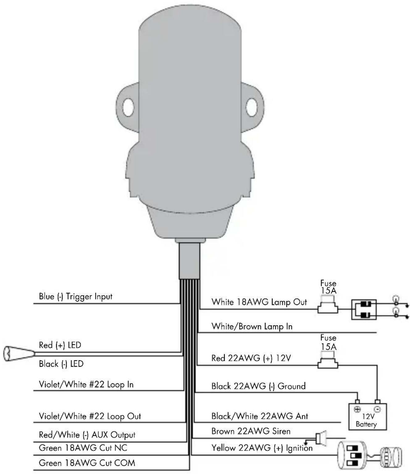
This input wire can be used as an instant trigger input for use with optional single zone sensors.
Violet/White Closed Loop
This wire can be used to protect a part of the vehicle where a trigger is desired when the wires of the connection are not in contact, rather than in contact. This closed loop connection is useful for protecting parts like saddlebags, luggage carriers, etc. that could be easily removed from the vehicle. Connect this wire through the object being protected. Then, if the contact is broken on this wire when the system is armed, the alarm will sound.
Red/White (-) AUX Output
This (-) 200mA output is used for controlling any Auxiliary function. This output can be programmed for pulse or latch output.
Important! Never connect the 200mA low current outputs directly to a motor or high current device WITHOUT a relay.
Green Wires (Starter Disable)
Use one of these wires as a starter kill input and the other as a starter kill output (these wires are interchangeable).

flowchart
graph LR
    A["Motor"] --> B["Cut"]
    B --> C["Starter Motor/Starter Motor Relay"]
    D["DEI Security System"] -->|Black/White| B
    D -->|Black/White| B
White Parking Light
This wire should be connected to the parking lights wire in the vehicle. It activates when the system is armed/disarmed, and when the alarm is triggered, it can be set for a (-) or (+) output. See the White/Brown parking light input wire for setting light flash polarity.
White/Brown Parking Light Input
This wire is used to select (+) or (-) parking light output:
• (+) parking light: Connect this wire to constant 12V from the vehicle
- (-) parking light: Connect this wire to chassis ground from the vehicle
Red (+) 12V Constant
This wire supplies power to the unit's micro-controller. Remove the supplied fuse before connecting to the (+) terminal of the battery or another constant (+) 12V supply. Make sure to replace the fuse when all connections have been made.
Note: Always use a fuse within 12 inches of the point from which you obtain (+) 12V. Do not use the 5A fuse in the harness for this purpose. This fuse protects the module only.
Black (-) Ground
This wire is the unit's source of ground. Do NOT connect this wire to any factory ground points; they can cause noise and/or voltage drops which can affect system performance. Ground the unit and any accessories to the same point in the vehicle (preferably the kick panel). Scrape away any paint and make your own ground with a screw and a star washer.
Black/White Antenna
This wire is the antenna for the control module to receive commands from the transmitter. Do NOT cut this wire.
Note: The antenna wire should not be bundled with the other harness wires as this will reduce the effective range of the transmitter. Keep the antenna wire as straight and horizontal as possible. Also, keep the antenna wire as far away as possible from metal.
Brown Siren (+) or Horn (-)
- Siren (+): If using the siren supplied with the system, connect this wire to the Red wire of the siren. The siren's black wire should be connected to chassis ground.
- Horn (-): This wire supplies a (-) 200mA output which can be used to honk the vehicle's horn. This wire outputs pulses during arm/disarm and when the alarm has been triggered.
Note: By default, this wire is (+) siren output. To change to (-) output for horn, change feature No. 5 to Negative
Yellow (+) Ignition
Connect this wire to an ignition wire. This wire must show (+) 12V with the key in the run position and during cranking. Make sure that this wire cannot be shorted to the chassis at any point
Government Regulations
This device complies with Part 15 of FCC rules. Operation is subject to the following two conditions: (1) This device may not cause harmful interference, and (2) This device must accept any interference received, including interference that may cause undesirable operation.
This equipment has been tested and found to comply with the limits for a Class B digital device, pursuant to Part 15 of the FCC Rules. These limits are designed to provide reasonable protection against harmful interference in a residential installation. This equipment generates and can radiate radio frequency energy and, if not installed and used in accordance with the instruction manual, may cause harmful interference to radio communications. However, there is no guarantee that interference will not occur in a particular installation. If this equipment does cause harmful interference to radio or television, which can be determined by turning the equipment OFF and ON, the user is encouraged to try to correct the interference by one or more of the following measures:
- Reorient or relocate the receiving antenna.
- Increase the separation between the equipment and receiver.
- Connect the equipment into an outlet on a circuit different from that to which the receiver is connected.
- Consult the dealer or an experienced radio / TV technician for help.
Remote Controls
To satisfy FCC RF exposure compliance requirements, this device should be used in hand-held, hand operated configurations only. The device and its antenna must maintain a separation distance of 20 cm or more from the person's body, except for the hand and wrists, to satisfy RF exposure compliance. This device is designed to be used in a person's hands and its operating configurations do not support normal transmissions while it is carried in pockets or holsters next to a person's body.
Control Center
To satisfy FCC RF exposure compliance requirements, the device and its antenna must maintain a separation distance of 20 cm or more from the person's body, except for the hand and wrists, to satisfy RF exposure compliance.
This device complies with the Industry Canada Radio Standards Specification RSS 210. Its use is authorized only on a no-interference, no-protection basis; in other words, this device must not be used if it is determined that it causes harmful interference to services authorized by IC. In addition, the user of this device must accept any radio interference that may be received, even if this interference could affect the operation of the device.
WARNING! Changes or modifications not expressly approved by the party responsible for compliance could void the user's authority to operate this device.
Limited Lifetime Consumer Warranty
Directed Electronics. ("Directed") promises to the original purchaser to repair or replace (at Directed's election) with a comparable reconditioned model any Directed unit (hereafter the "unit"), excluding without limitation the siren, the remote transmitters, the associated sensors and accessories, which proves to be defective in workmanship or material under reasonable use during the lifetime of the vehicle provided the following conditions are met: the unit was purchased from an authorized Directed dealer, the unit was professionally installed and serviced by an authorized Directed dealer; the unit will be professionally reinstalled in the vehicle in which it was originally installed by an authorized Directed dealer; and the unit is returned to Directed, shipping prepaid with a legible copy of the bill of sale or other dated proof of purchase bearing the following information: consumer's name, telephone number and address; the authorized dealers name, telephone number and address; complete product description, including accessories; the year, make and model of the vehicle; vehicle license number and vehicle identification number. All components other than the unit, including without limitation the siren, the remote transmitters and the associated sensors and accessories, carry a one-year warranty from the date of purchase of the same. ALL PRODUCTS RECEIVED BY DIRECTED FOR WARRANTY REPAIR WITHOUT PROOF OF PURCHASE FROM AN AUTHORIZED DEALER WILL BE DENIED. This warranty is non-transferable and is automatically void if: the unit's date code or serial number is defaced, missing or altered; the unit has been modified or used in a manner contrary to its intended purpose; the unit has been damaged by accident, unreasonable use, neglect, improper service, installation or other causes not arising out of defects in materials or construction. The warranty does not cover damage to the unit caused by installation or removal of the unit. Directed, in its sole discretion, will determine what constitutes excessive damage and may refuse the return of any unit with excessive damage.
TO THE MAXIMUM EXTENT ALLOWED BY LAW, ALL WARRANTIES, INCLUDING BUT NOT LIMITED TO EXPRESS WARRANTY, IMPLIED WARRANTY, WARRANTY OF MERCHANTABILITY, FITNESS FOR PARTICULAR PURPOSE AND WARRANTY OF NON-INFRINGEMENT OF INTELLECTUAL PROPERTY, ARE EXPRESSLY EXCLUDED; AND DIRECTED NEITHER ASSUMES NOR AUTHORIZES ANY PERSON OR ENTITY TO
ASSUME FOR IT ANY DUTY, OBLIGATION OR LIABILITY IN CONNECTION WITH ITS PRODUCTS. DIRECTED DISCLAIMS AND HAS ABSOLUTELY NO LIABILITY FOR ANY AND ALL ACTS OF THIRD PARTIES INCLUDING ITS AUTHORIZED DEALERS OR INSTALLERS. DIRECTED SECURITY SYSTEMS, INCLUDING THIS UNIT, ARE DETERRENTS AGAINST POSSIBLE THEFT. DIRECTED IS NOT OFFERING A GUARANTEE OR INSURANCE AGAINST VANDALISM, DAMAGE OR THEFT OF THE AUTOMOBILE, ITS PARTS OR CONTENTS; AND HEREBY EXPRESSLY DISCLAIMS ANY LIABILITY WHATSOEVER, INCLUDING WITHOUT LIMITATION, LIABILITY FOR THEFT, DAMAGE AND/OR VANDALISM. THIS WARRANTY DOES NOT COVER LABOR COSTS FOR MAINTENANCE, REMOVAL OR REINSTALLATION OF THE UNIT OR ANY CONSEQUENTIAL DAMAGES OF ANY KIND. IN THE EVENT OF A CLAIM OR A DISPUTE INVOLVING DIRECTED OR ITS SUBSIDIARY, THE VENUE SHALL BE SAN DIEGO COUNTY IN THE STATE OF CALIFORNIA. CALIFORNIA STATE LAWS AND APPLICABLE FEDERAL LAWS SHALL APPLY AND GOVERN THE DISPUTE. THE MAXIMUM RECOVERY UNDER ANY CLAIM AGAINST DIRECTED SHALL BE STRICTLY LIMITED TO THE AUTHORIZED DIRECTED DEALER'S PURCHASE PRICE OF THE UNIT. DIRECTED SHALL NOT BE RESPONSIBLE FOR ANY DAMAGES WHATSOEVER, INCLUDING BUT NOT LIMITED TO, ANY CONSEQUENTIAL DAMAGES, INCIDENTAL DAMAGES, DAMAGE TO VEHICLE, DAMAGES FOR THE LOSS OF TIME, LOSS OF EARNINGS, COMMERCIAL LOSS, LOSS OF ECONOMIC OPPORTUNITY AND THE LIKE. NOTWITHSTANDING THE ABOVE, THE MANUFACTURER DOES OFFER A LIMITED WARRANTY TO REPLACE OR REPAIR THE CONTROL MODULE SUBJECT TO THE CONDITIONS AS DESCRIBED HEREIN. THIS WARRANTY IS VOID IF THE UNIT HAS NOT BEEN PURCHASED FROM DIRECTED, OR AN AUTHORIZED DIRECTED DEALER, OR IF THE UNIT HAS BEEN DAMAGED BY ACCIDENT, UNREASONABLE USE, NEGLIGENCE, ACTS OF GOD, NEGLECT, IMPROPER SERVICE, OR OTHER CAUSES NOT ARISING OUT OF DEFECT IN MATERIALS OR CONSTRUCTION.
Some states do not allow limitations on how long an implied warranty will last or the exclusion or limitation of incidental or consequential damages. This warranty gives you specific legal rights and you may also have other rights that vary from State to State.
This warranty is only valid for sale of product(s) within the United States of America and in Canada. Product(s) sold outside of the United States of America or Canada are sold "AS-IS" and shall have NO WARRANTY, express or implied.
For further details relating to warranty information of Directed products, please visit the support section of Directed's website at: www.directed.com.
This product may be covered by a Guaranteed Protection Plan ("GPP"). See your authorized Directed dealer for details of the plan or call Directed Customer Service at 1-800-876-0800.
920-10011-01 2011-06




- VIPER®
- Table of Contents
- Congratulations
- Standard Remote Configuration
- 2-Button Transmitter
- Remote Learning
- Arming
- Ignition Trigger
- Tilt/Shock Sensor Trigger
- Arming and Bypassing Tilt Sensor
- Arming and Bypassing Tilt and Shock Sensor
- Disarming
- Aux
- Auto Re-Arming
- Panic
- Anti Motorcycle-Jacking
- Emergency Override
- Pin Number Setting
- Factory Preset Pin Number: 1 (Led Blinks One Time)
- Confirm the original (preset) PIN Number
- Input the new PIN NUMBER
- Exit Pin Number Setting
- Valet Mode
- Enter Valet Mode
- Memory Function
- Feature Settings
- Power Saving (Sleep) Mode
- System Maintenance
- Battery Replacement
- Battery Disposal
- Blue (-) Trigger Input
- Violet/White Closed Loop
- Red/White (-) AUX Output
- Green Wires (Starter Disable)
- White Parking Light
- White/Brown Parking Light Input
- Red (+) 12V Constant
- Black (-) Ground
- Black/White Antenna
- Brown Siren (+) or Horn (-)
- Yellow (+) Ignition
- Government Regulations
- Remote Controls
- Control Center
- Limited Lifetime Consumer Warranty
Brand : Viper
Model : 3121V
Category : Car alarm