
211HV - Car alarm Viper - Free user manual and instructions
Find the device manual for free 211HV Viper in PDF.


| Product Type | Car Alarm System |
| Brand | Viper (Directed) |
| Model | 211HV |
| Input Voltage | 12V DC (negative ground) |
| LED Indicator | Super bright LED (2V DC), 9/32-inch mounting hole |
| Transmitters Included | Two 4-button transmitters |
| Transmitter Battery | Two 3V lithium CR2016 (per remote) |
| Keyless Entry Range | Up to 100 feet (typical) |
| Door Lock Output | Onboard relays, up to 30A |
| Parking Light Output | High current (+/-) flash output |
| Horn Honk Output | 200 mA negative |
| Starter Kill Output | 500 mA ground-when-armed |
| Auxiliary Outputs | Channel 2: 200 mA negative; Channel 3: 200 mA negative |
| Domelight Supervision | Up to 30A via onboard relay |
| Programmable Features | 8 features: ignition lock/unlock, pulse duration, double pulse, comfort closure, code hopping |
| Memory | Rapid Resume Logic (non-volatile) |
| Dimensions (approx.) | 4.0 x 3.0 x 1.0 in (100 x 75 x 25 mm) |
| Weight (approx.) | 5 oz (140 g) |
| Warranty | Limited lifetime on control module; 1 year on accessories |
| Installation | Professional installation required |
| Compliance | FCC Part 15 |
Frequently Asked Questions - 211HV Viper
User questions about 211HV Viper
0 question about this device. Answer the ones you know or ask your own.
Ask a new question about this device
Download the instructions for your Car alarm in PDF format for free! Find your manual 211HV - Viper and take your electronic device back in hand. On this page are published all the documents necessary for the use of your device. 211HV by Viper.
USER MANUAL 211HV Viper
NOTE: This product is intended for installation by a professional installer only! Any attempt to install this product by any person other than a trained professional may result in severe damage to a vehicle's electrical system and components.
Code Hopping ^® , Learn Routine ^TM , Valet ^® , are all Trademarks or Registered Trademarks of Directed.
Table of Contents
Primary harness (H1), 18-pin connector....4
Peripheral Plug-In Harnesses....8
Super Bright LED, 2-Pin WHITE Plug....8
Valet/Program Switch, 2-Pin BLUE Plug....9
System Features Learn Routine....9
System Features Menus....11
Feature Descriptions ....11
Transmitter/Receiver Learn Routine....12
Transmitter Configurations....14
Standard Configuration ....14
Rapid Resume Logic....14
Wiring Quick Reference Guide....15
Primary harness (H1), 18-pin connector
| H1/1 | RED (+) 12V CONSTANT POWER INPUT |
| H1/2 | BLUE (-) 200mA SECOND DOOR UNLOCK OUTPUT |
| H1/3 | BLACK/WHITE-1 DOMELIGHT SUPERVISION RELAY INPUT #87 |
| H1/4 | BLACK/WHITE DOMELIGHT SUPERVISION RELAY OUTPUT #30 |
| H1/5 | GREEN/BLACK DOOR LOCK #30 COMMON OUTPUT |
| H1/6 | WHITE/BLACK DOOR LOCK #87 NORMALLY CLOSED |
| H1/7 | VIOLET/BLACK DOOR LOCK #87 NORMALLY OPEN (INPUT) |
| H1/8 | BLUE/BLACK DOOR UNLOCK #30 COMMON (OUTPUT) |
| H1/9 | VIOLET DOOR UNLOCK #87 NORMALLY OPEN (INPUT) |
| H1/10 | WHITE (+/-) PARKING LIGHT FLASH OUTPUT |
| H1/11 | BLACK (-) CHASSIS GROUND INPUT |
| H1/12 | BROWN (-) HORN HONK OUTPUT |
| H1/13 | LT. GREEN/BLACK (-) 200mA FACTORY ALARM/DISARM OUTPUT |
| H1/14 | WHITE/BLUE (-) 200mA CHANNEL 3 VALIDITY OUTPUT |
| H1/15 | YELLOW (+) SWITCHED IGNITION SENSE INPUT |
| H1/16 | ORANGE (-) 500mA GROUND-WHEN-ARMED OUTPUT |
| H1/17 | BROWN/BLACK DOOR UNLOCK #87A NORMALLY CLOSED |
| H1/18 | RED/WHITE (-) 200mA CHANNEL 2 OUTPUT |
H1/1 RED (+) 12V Constant Power Input
Before connecting this wire, remove the supplied fuse. Connect to the battery positive terminal or the constant 12V supply to the ignition switch.
NOTE: Always use a fuse within 12 inches of the point you obtain (+) 12V. Do not use the fuse in the harness for this purpose. This fuse protects the module itself.
H1/2 BLUE (-) 200 mA Second Unlock Output
The H1/2 BLUE output is used for progressive unlock. A progressive unlock system unlocks the driver's door when the unlock (disarm) button is pressed and unlocks the passenger doors if the unlock (disarm) button is pressed again within 15 seconds after unlocking the driver's door. The BLUE wire outputs a low current (-) pulse on the second press of the unlock button of the transmitter. This negative unlock output is used to unlock the passenger doors.
H1/3 BLACK/WHITE Domelight Supervision Input
This wire determines what the output polarity of H1/4 will be. If the domelight circuit is negative, connect to chassis ground. If the domelight circuit is positive trigger, connect to a fused (+)12V source.
H1/4 BLACK/WHITE Domelight Supervision Output
Connect this wire directly to the domelight circuit in the vehicle. The on-board relay will drive circuits up to 30 amperes. The polarity of this output is determined by the connection of the input wire H1/3 in the Relay Harness.
NOTE: If the input wire H1/3 is not connected, there will be no output on this wire.
H1/5 GREEN/BLACK Door Lock #30 Common (Output)
The system has door lock relays on-board, and can directly interface with most electric power door lock systems drawing 30 amps or less. It can also drive aftermarket actuators directly. (Some vehicles require that an aftermarket actuator be added to the driver's door to allow system control, see Type D wiring section in Tech Tip Document 1041).
H1/6 WHITE/BLACK Door Lock #87 Normally Closed See H1/5.
H1/7 VIOLET/BLACK Door Lock #87 Normally Opened (Input) See H1/5.
H1/8 BLUE/BLACK Door Unlock #30 Common (Output) See H1/5.
H1/9 VIOLET Door Unlock #87 Normally Open (Input) See H1/5.
H1/10 WHITE (+/-) Parking Light Flash Output
This wire provides a high current (+) or (-) output to flash the parking lights (+) is factory default setting). For driving (-) negative parking lights, the light flash jumper on the control module must be moved.
H1/11 BLACK (-) Chassis Ground Connection
Connect this wire to a clean, paint-free sheet metal location (driver kick panel) using a factory bolt that DOES NOT have any vehicle component grounds attached to it. A screw should only be used when in conjunction with a two-sided lock washer. Under dash brackets and door sheet metal are not acceptable ground points. It is recommended that all security components be grounded at the same location.

H1/12 BROWN (-) Horn Honk Output
This wire supplies a (-) 200 mA output that can be used to honk the vehicle horn*. It can output a single (-) pulse when locking the doors with the remote, and two (-) pulses when unlocking with the remote. This wire will also output for 30 seconds when Panic Mode is activated. If the vehicle has a (+) horn circuit, an optional relay can be used to interface with the system, as shown below.

flowchart
graph TD
    A["H1/12 BROWN"] --> B["85"]
    A --> C["86"]
    D["(+) 12V CONSTANT FUSED"] --> B
    E["(+) 12V CONSTANT FUSED"] --> C
    B --> F["87"]
    C --> G["87A"]
    F --> H["30"]
    G --> I["30"]
    J["(+) HORN CIRCUIT IN VEHICLE"] --> K["30"]
* The horn will honk only when in audible mode by pressing the 🔒 button on the remote twice or by pressing the AUX button on the remote prior to locking/unlocking
H1/13 LT. GREEN/BLACK Factory Alarm Disarm
This wire supplies a (-) 200mA pulse every time the alarm is disarmed or the optional remote start is activated. This can be used to pulse the disarm wire of the vehicle's factory anti-theft device. This also outputs when Channel 2 is activated.
H1/14 WHITE/BLUE (-) Channel 3 Validity Output
This wire provides a (-) 200mA output whenever the transmitter code controlling Channel 3 is received. This output will continue as long as that transmission is received. Use for options such as Directed's add-on Remote Start Systems, 529T or 535T power window controllers, etc.
IMPORTANT! Never use ANY 200mA (-) output to drive anything but a relay or a low-current input! The transistorized output can only provide 200mA of current, and connecting directly to a solenoid, motor, or other high-current device will cause it to fail.
H1/15 YELLOW (+) Switched Ignition Sense Input
Connect this wire to an ignition source. This input must show (+)12V with the key in run position and during cranking. This wire will trigger the system if the ignition is turned on before the unit is disarmed (doors unlocked with the remote). It will also honk the vehicle's horn and flash the parking lights (if connected).

flowchart
graph LR
    A["DM-17"] --> B["H1/15 YELLOW PRIMARY HARNESS"]
    B --> C["TO IGNITION SYSTEM"]
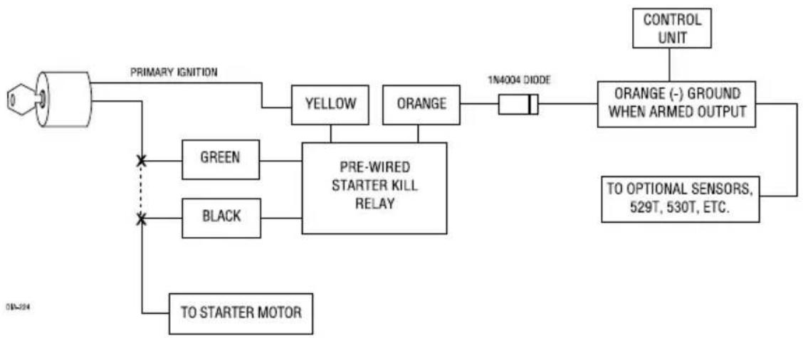
H1/16 ORANGE (-) 500mA Ground-When Armed Output
This wire supplies a (-) 500mA ground as long as the system is armed. This output ceases as soon as the system is disarmed.
Note: If using the H1/16 Orange wire to activate an add-on accessory such as remote start, window automation, module a 1-Amp diode must be installed to ensure proper operation. Insert the diode as shown the following diagram.
flowchart
graph TD
    A["Power Line"] --> B["PRIMARY IGNITION"]
    B --> C["GREEN"]
    B --> D["BLACK"]
    B --> E["TO STARTER MOTOR"]
    C --> F["PRE-WIRED STARTER KILL RELAY"]
    D --> F
    E --> F
    F --> G["YELLOW"]
    F --> H["ORANGE"]
    G --> I["1N4004 DIODE"]
    H --> I
    I --> J["ORANGE (-) GROUND WHEN ARMED OUTPUT"]
    J --> K["CONTROL UNIT"]
    J --> L["TO OPTIONAL SENSORS, 529T, 530T, ETC."]
H1/17 BROWN/BLACK Door Unlock #87A Normally Closed
See H1/5.
H1/18 RED/WHITE (-) 200mA Channel 2 Output
When the system receives the transmitter code controlling Channel 2 for longer than 1.5 seconds, the red/white wire will supply an output as long as the transmission continues. This is often used to operate a trunk/hatch release or other relay-driven functions.
IMPORTANT! Never use ANY 200mA (-) output to drive anything but a relay or a low-current input! The transistorized output can only supply 200mA of current. Connecting directly to a solenoid, motor, or other high-current device will cause it to fail.

flowchart
graph TD
    A["H1/18 RED/WHITE"] --> B["85"]
    C["(+) 12V CONSTANT FUSED"] --> D["86"]
    B --> E["87"]
    D --> F["30"]
    G["(+) 12V INPUT FOR (+) TRIGGER\n(-) GROUND INPUT FOR (-) TRIGGER"] --> E
    H["(-) OR (+) TRUNK RELEASE OUTPUT"] --> F
Peripheral Plug-In Harnesses
Super Bright LED, 2-Pin WHITE Plug
The super bright LED operates at (+) 2 Volt DC and plugs into the two-pin WHITE port. Make sure the LED wires are not shorted to ground as the LED will be damaged. Multiple LED's can be used, but they must be wired in series. The LED fits into a 9/32-inch mounting hole. Be sure to check for clearance prior to drilling the mounting hole.
NOTE: Never wire a BLUE colored LED in series with a RED colored LED.

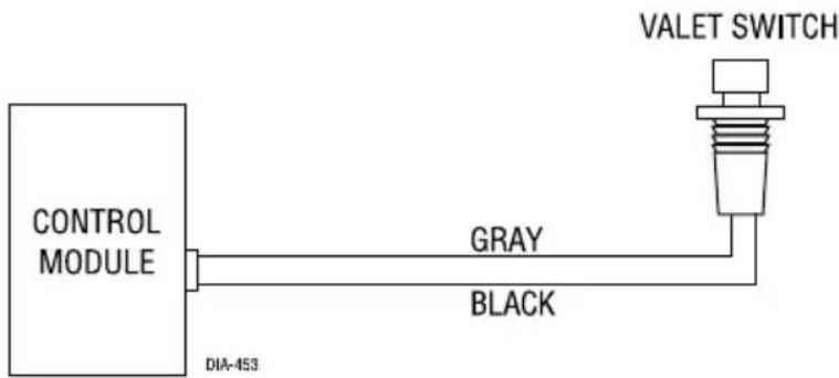
Valet/Program Switch, 2-Pin BLUE Plug
The Valet/Program button should be accessible from the driver's seat. It plugs into the BLUE port on the side of the unit. Consider how the button will be used before choosing a mounting location. Check for rear clearance before drilling a 9/32-inch hole and mounting the button.
System Features Learn Routine
The System Features Learn Routine dictates how the unit operates. It is possible to access and change any of the feature settings using the Valet®/Program switch.
To enter the Learn Routine:

- Key. Turn the ignition on and then back off.
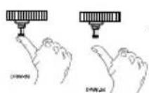
- Choose. Within 10 seconds, press and release the Valet ^ /Program switch the number of times corresponding to the feature number you want to program. (See Feature Menus.) Once the Valet ^ /Program switch has been pressed and released the desired number of times, press it once more and hold it. After a second, the LED will flash and the horn will honk to indicate which feature you have accessed.

- Transmit. The transmitter is used to select the desired setting. As shipped, the unit is configured to the LED ON settings. These are the default settings. Pressing the lock button will set it to the LED ON setting. The LED will light solid (stop flashing) to indicate the setting. The horn will honk once (if connected). Pressing the unlock button will change the setting to the LED OFF setting. The LED will go out indicating the change and the horn will honk twice (if connected).
For example, to program the arming mode from active to passive, within 10 seconds of turning the ignition off, and press and release the Valet/Program switch once. Then press it again and hold it. The LED will flash in groups of one and the horn will honk once (if connected). While holding the Valet®/Program switch, press the unlock button. The LED will stop flashing and go out. The horn will honk twice if connected. Passive arming is now programmed. If that was not the desired setting, without releasing the Valet®/Program switch, press the lock button. The LED will light solid and the horn will honk once if connected. Active arming is now programmed. Release the Valet®/Program switch after the selection has been made.
You can advance from feature to feature by pressing and releasing the Valet®/Program switch the number of times necessary to get from the feature you just programmed to the feature you wish to access. For example, if you just programmed Feature 2 and you next want to program Feature 3 to off, release the Valet®/Program switch. Press and release it once to advance from Feature 2 to Feature 3. Then press it once more and hold it. The LED will flash in groups of three and the horn will honk three times (if connected) to confirm that you have accessed Feature 3.
The Learn Routine will be exited if:
• The ignition is turned on.
• The Valet/Program switch is pressed too many times.
• More than 15 seconds elapses between programming steps.
One long horn honk (if connected) indicates that the Learn Routine has been exited.
System Features Menus
| Feature Default LED ON Setting LED OFF Setting Number (Press Channel 1) (Press Channel 2) | ||
| 1 | Ignition-controlled door lock ON Ignition-controlled door lock OFF | |
| 2 | Ignition-controlled door unlock ON Ignition-controlled door unlock OFF | |
| 3 | Ignition-controlled domelight ON Ignition-controlled domelight OFF | |
| 4 | 0.8 second door lock pulses | 3.5 second door lock pulses/0.4 sec. |
| 5 | Double pulse unlock OFF Double pulse unlock ON | |
| 6 | Double pulse lock OFF Double pulse lock ON | |
| 7 | Comfort closure OFF | Comfort closure ON |
| 8 | Code Hopping ON | Code Hopping OFF |
Note: Factory default settings are shown in BOLD.
Feature Descriptions
The features of the system are described below.
1 IGNITION CONTROLLED DOOR LOCK ON/OFF: When turned on, the doors will lock three seconds after the ignition is turned on.
2 IGNITION CONTROLLED DOOR UNLOCK ON/OFF: When turned on, the doors will unlock when the ignition is turned off.
3 IGNITION CONTROLLED DOMELIGHT: If turned on, the system will turn on the domelight for 30 seconds when the ignition is turned off. The domelight supervision output (H1/4) wire must be connected as described in the Primary Harness Wire Connection Guide.
4 DOOR LOCK PULSE DURATION: Some European vehicles, such as Mercedes-Benz and Audi, require longer lock and unlock pulses to operate the vacuum pump. Programming the system to provide 3.5 second pulses will accommodate the door lock interface in these vehicles. The default setting is 0.8 second door lock pulses. For some vehicles a 0.4 second pulse duration is required, this durations is required for some vehicles to prevent the windows from moving.
5 DOUBLE PULSE UNLOCK OFF/ON: Some vehicles require two pulses on a single wire to unlock the doors. When the double pulse unlock feature is turned on, the BLUE/BLACK H1/8
wire will supply two negative pulses instead of a single pulse.
6 DOUBLE PULSE LOCK OFF/ON. Selectable 2 pulse door lock output to operate vehicle equipped with factory “deadbolt”. Will have similar operation to that of the Double Pulse Unlock feature, but will perform the functions on the Lock wire as opposed to the Unlock wire.
7 COMFORT CLOSURE FEATURE OFF/ON: This feature is designed to integrate with vehicles that can close the power windows and sunroof by holding the key in the driver door lock position, and will operate on both single input systems and two pulses input dead bolt systems.
If programmed ON the door lock output will activate the Comfort Close output for 20 seconds. This output will begin 200ms after the final door lock output has completed regardless of the door lock programming.
If while the 20 second timer is active and closing the windows the user disarms the unit, the Comfort Close output will immediately cease before the doors unlock.
8 CODE-HOPPING ON/OFF: The system features Code Hopping as an option.
Transmitter/Receiver Learn Routine
The system comes with two transmitters that have been taught to the receiver. The receiver can store up to four different transmitter codes in memory. Use the following Learn Routine to add transmitters to the system or to change button assignments if desired.


-
Key. Turn the key to the ON position.
-
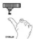
Choose. Within 10 seconds, press and release the Valet/program switch the number of times corresponding to the desired channel listed below. Once you have selected the channel, press the switch once more and HOLD it. The LED will flash and the horn will honk (if connected) to confirm the selected channel. Do not release the Valet/program switch.

-
Transmit. While holding the Valet/Program button, press the button from the transmitter that you wish to assign to the selected channel. The horn will honk (if connected) indicating successful programming. It is not possible to teach a transmitter button to the system more than once.
-
Release. Once the code is learned, the Valet/Program button can be released.
| Channel Number Function | Wire Color | |
| 1 | Auto Learn* | |
| 2 | Arm only | |
| 3 | Disarm only | |
| 4 | Channel 2 RED/WHITE | |
| 5 | Channel 3 WHITE/BLUE | |
| 6 | Arm/Disarm/Panic | |
| 7 | Panic Only | |
| 8 | Delete all transmitters | |
| *NOTE: For Auto Learn Configurations, see Transmitter Configurations section of this guide. | ||
Channel #8: If any button from a known transmitter is programmed to Channel 8, all transmitters will be erased from memory and the system features will revert to the default settings. This is useful in cases where the one of the customer's transmitters is lost or stolen. This will erase any lost or stolen transmitters from the system's memory. It can also be used to start from scratch if the transmitter buttons were programmed incorrectly.
To exit the Learn Routine:
One long horn honk indicates that Learn Routine has been exited.
- Ignition is turned off.
• Valet/Program button is pressed too many times.
• More than 15 seconds elapse between steps.
Transmitter Configurations
The transmitters can be programmed with the standard or single button arm/disarm configurations by using the Auto Learn functions in the Transmitter/Receiver Learn Routine.
Standard Configuration
A remote that uses the standard configuration operates similarly to many factory keyless entry remotes. A standard configuration transmitter allows arming, disarming, and Panic Mode activation with separate buttons. When programmed for standard configuration using the Channel 1 Auto-learn configuration, the transmitter buttons are assigned to the following functions:

Rapid Resume Logic
Rapid Resume Logic ensures that the when the system is powered up it will return to the same state it was in when power is disconnected. For a full description of Rapid Resume Logic refer to the owner's manual.
Wiring Quick Reference Guide

The company behind this system is Directed
Since its inception, Directed has had one purpose, to provide consumers with the finest vehicle security and accessories available. The recipient of nearly 100 patents and Innovations Awards in the field of advanced electronic technology.
Quality Directed products are sold and serviced throughout North America and around the world.
Call (800) 274-0200 for more information about our products and services.
DIRECTED.
N412V 2018-02
Vista, CA 92081
www.directed.com
© 2018 Directed.—All rights reserved.
DIRECTED.
The company behind Viper® Auto Security Systems is Directed.
Since its inception, Directed has had one purpose, to provide consumers with the finest vehicle security and accessories available. The recipient of nearly 100 patents and Innovations Awards in the field of advanced electronic technology.
Quality Directed products are sold and serviced throughout North America and around the world.
Call (800) 876-0800 for more information about our products and ser vic es.
© 2019 Directors. At rights reserved.
590-10126 (R1.1)
0412V 2019-01
Viper®
NO ONE DARES COME CLOSE

natural_image
Illustration of a snake's head with open mouth and large eyes, set against a solid yellow background (no text or symbols)Vista, CA 92081
www.viper.com
Directed is committed to delivering world class quality products and services that excite and delight our customers.
OWNER'S GUIDE
M O D E L
211HV
limited lifetime consumer warranty
Directed Electronics. (“Directed”) promises to the original purchaser to repair or replace (at Directed’s election) with a comparable reconditioned model any Directed unit (hereafter the “unit”), excluding without limitation the siren, the remote transmitters, the associated sensors and accessories, which proves to be defective in workmanship or material under reasonable use during the lifetime of the vehicle provided the following conditions are met: the unit was purchased from an authorized Directed dealer, the unit was professionally installed and serviced by an authorized Directed dealer; the unit will be professionally reinstalled in the vehicle in which it was originally installed by an authorized Directed dealer; and the unit is returned to Directed, shipping prepaid with a legible copy of the bill of sale or other dated proof of purchase bearing the following information: consumer’s name, telephone number and address; the authorized dealers name, telephone number and address; complete product description, including accessories; the year, make and model of the vehicle; vehicle license number and vehicle identification number. All components other than the unit, including without limitation the siren, the remote transmitters and the associated sensors and accessories, carry a one-year warranty from the date of purchase of the same. ALL PRODUCTS RECEIVED BY DIRECTED FOR WARRANTY REPAIR WITHOUT PROOF OF PURCHASE FROM AN AUTHORIZED DEALER WILL BE DENIED. This warranty is non-transferable and is automatically void if: the unit’s date code or serial number is defaced, missing or altered; the unit has been modified or used in a manner contrary to its intended purpose; the unit has been damaged by accident, unreasonable use, neglect, improper service, installation or other causes not arising out of defects in materials or construction. The warranty does not cover damage to the unit caused by installation or removal of the unit. Directed, in its sole discretion, will determine what constitutes excessive damage and may refuse the return of any unit with excessive damage.
TO THE MAXIMUM EXTENT ALLOWED BY LAW, ALL WARRANTIES, INCLUDING BUT NOT LIMITED TO EXPRESS WARRANTY, IMPLIED WARRANTY, WARRANTY OF MERCHANTABILITY, FITNESS FOR PARTICULAR PURPOSE AND WARRANTY OF NON-INFRINGEMENT OF INTELLECTUAL PROPERTY, ARE EXPRESSLY EXCLUDED; AND DIRECTED NEITHER ASSUMES NOR AUTHORIZES ANY PERSON OR ENTITY TO ASSUME FOR IT ANY DUTY, OBLIGATION OR LIABILITY IN CONNECTION WITH ITS PRODUCTS. DIRECTED DISCLAIMS AND HAS ABSOLUTELY NO LIABILITY FOR ANY AND ALL ACTS OF THIRD PARTIES INCLUDING ITS AUTHORIZED DEALERS OR INSTALLERS. DIRECTED SECURITY SYSTEMS, INCLUDING THIS UNIT, ARE DETERRENTS AGAINST POSSIBLE THEFT. DIRECTED IS NOT OFFERING A GUARANTEE OR INSURANCE AGAINST VANDALISM, DAMAGE OR THEFT OF THE AUTOMOBILE, ITS PARTS OR CONTENTS; AND HEREBY EXPRESSLY DISCLAIMS
ANY LIABILITY WHATSOEVER, INCLUDING WITHOUT LIMITATION, LIABILITY FOR THEFT, DAMAGE AND/OR VANDALISM. THIS WARRANTY DOES NOT COVER LABOR COSTS FOR MAINTENANCE, REMOVAL OR REINSTALLATION OF THE UNIT OR ANY CONSEQUENTIAL DAMAGES OF ANY KIND. IN THE EVENT OF A CLAIM OR A DISPUTE INVOLVING DIRECTED OR ITS SUBSIDIARY, THE VENUE SHALL BE SAN DIEGO COUNTY IN THE STATE OF CALIFORNIA. CALIFORNIA STATE LAWS AND APPLICABLE FEDERAL LAWS SHALL APPLY AND GOVERN THE DISPUTE. THE MAXIMUM RECOVERY UNDER ANY CLAIM AGAINST DIRECTED SHALL BE STRICTLY LIMITED TO THE AUTHORIZED DIRECTED DEALER'S PURCHASE PRICE OF THE UNIT. DIRECTED SHALL NOT BE RESPONSIBLE FOR ANY DAMAGES WHATSOEVER, INCLUDING BUT NOT LIMITED TO, ANY CONSEQUENTIAL DAMAGES, INCIDENTAL DAMAGES, DAMAGE TO VEHICLE, DAMAGES FOR THE LOSS OF TIME, LOSS OF EARNINGS, COMMERCIAL LOSS, LOSS OF ECONOMIC OPPORTUNITY AND THE LIKE. NOTWITHSTANDING THE ABOVE, THE MANUFACTURER DOES OFFER A LIMITED WARRANTY TO REPLACE OR REPAIR THE CONTROL MODULE SUBJECT TO THE CONDITIONS AS DESCRIBED HEREIN. THIS WARRANTY IS VOID IF THE UNIT HAS NOT BEEN PURCHASED FROM DIRECTED, OR AN AUTHORIZED DIRECTED DEALER, OR IF THE UNIT HAS BEEN DAMAGED BY ACCIDENT, UNREASONABLE USE, NEGLIGENCE, ACTS OF GOD, NEGLECT, IMPROPER SERVICE, OR OTHER CAUSES NOT ARISING OUT OF DEFECT IN MATERIALS OR CONSTRUCTION.
Some states do not allow limitations on how long an implied warranty will last or the exclusion or limitation of incidental or consequential damages. This warranty gives you specific legal rights and you may also have other rights that vary from State to State.
This warranty is only valid for sale of product(s) within the United States of America and in Canada. Product(s) sold outside of the United States of America or Canada are sold “AS-IS” and shall have NO WARRANTY, express or implied.
For further details relating to warranty information of Directed products, please visit the support section of Directed's website at: www.directed.com
This product may be covered by a Guaranteed Protection Plan (“GPP”). See your authorized Directed dealer for details of the plan or call Directed Customer Service at 1-800-876-0800.
920-10011-01 2011-06
table of contents
limited lifetime consumer warranty....i
standard transmitter configuration....4
what is included....4
important information ....5
system maintenance....5
your warranty....5
fcc/id notice....6
transmitter functions 6
standard configuration....7
using your system 8
locking/arming 8
unlocking/disarming....9
disabling the system without a transmitter 9
audible mode.... 10
valet mode.... 10
panic mode.... 11
rapid resume logic 12
programming options....12
glossary of terms....13
patent information 16
standard transmitter configuration

controls the Arm function.

controls the Disarm function.

controls Audible Mode and an Auxiliary Output.

controls the Panic function.

and ▶ pressed together control an Auxiliary Output.
what is included
- The control module
- Super het receiver
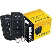
• A pair of four-button trans mit ters
• A status LED indicator light - A push-button Valet ^® switch
- Your warranty registration
important information
Congratulations on the purchase of your keyless entry system. Due to the complexity of this system, it must be installed by an authorized dealer only. Installation of this product by anyone other than an authorized dealer voids the warranty. All dealers are provided with a preprinted dealer cer tif i cate to verify that they are au thorized.
By carefully reading this Owner's Guide prior to using your system, you will maximize the use of this system and its features.
You can print additional or replacement copies of this manual by accessing the Directed web site at www.directed.com.
system maintenance
The system requires no specific main tenance. Your remote is powered by a small, lightweight 3-volt lithium battery (2-CR2016) that will last approximately one year under normal use. When the battery begins to weaken, operating range will be reduced and the LED on the remote will dim.
your warranty
Your warranty registration must be completely filled out and returned within 10 days of purchase. Your product warranty will not be validated if your warranty registration is not returned. Make sure you receive the warranty registration from your dealer. It is also necessary to keep your proof of purchase, which reflects that the product was installed by an au tho rized dealer.
fcc/id notice
This device complies with Part 15 of FCC rules. Operation is subject to the following con di tions: (1) This device may not cause harmful interference, and (2) This device must accept any in ter-fer ence re ceived, including in ter fer ence that may cause undesirable operation.
Changes or modifications not expressly approved by the party responsible for compliance could void the user's authority to operate this device.
Directed Electronics, Inc.
412 Series

Tested to Comply with FCC Standards
transmitter functions
The receiver uses a computer-based learn routine to learn the transmit ter buttons. This makes it possible to assign any specific transmitter button, or combination of buttons, to any receiver function. The transmitter initially comes programmed with the Standard Configuration, but may also be customized by an authorized dealer. The transmitter buttons indicated in all of the instructions in this manual correspond to a Standard Configuration transmitter.
standard configuration

Button
The locking/arming function is controlled by pressing this button for one second. Pressing 🔒 a 2nd time (within 5 seconds) after arming will honk the horn.

Button
The unlocking/disarming function is controlled by pressing this button for one second.

Button
Press and release this button prior to pressing the Lock or Unlock button to temporarily enable the audible mode.
To activate the auxiliary output, press and hold this button for 1.5 seconds.
The auxiliary output controls ____.

Button
The panic feature is controlled by pressing this button for one second.

and

Buttons
An optional auxiliary convenience or expansion function that you have added to your system can be activated by pressing these buttons simultaneously.
The auxiliary output controls ____.
locking/arming
Pressing 📄 for one second arms the system by activating the starter kill (optional) and locking the doors (if connected). The horn will honk (if connected and in audible mode, see “audible mode” on page 10) and the parking lights will flash once to confirm arming of the system. While the system is armed, the status LED will flash once per second. The Failsafe® Starter Kill (if in stalled) will also prevent the vehicle’s starter from cranking.
note: Manually locking the vehicle does not arm the system; it will only lock the doors.
The system can also be programmed to arm the optional Failsafe ^® Starter Kill automatically (called Passive Mode). If the system has been programmed for Passive Mode, the Failsafe ^® Starter Kill will automatically activate 30 seconds after the ignition has been turned off. After the ignition has been turned off, the status LED will flash rapidly to indicate that the system is in Passive Mode.
If Passive Mode has been programmed on, then it is also possible to program the system for Passive Locking. With Passive Locking, the vehicle doors lock automatically at the same time that the Failsafe ^® Starter Kill is activated. If Passive Locking is programmed on, care must be taken to prevent the keys from being locked in the vehicle.
note: For Passive Mode to be effective, the Failsafe® Starter Kill relay must be installed.
unlocking/disarming
Pressing 📁 for one second disarms the system and unlocks the doors (if connected). The horn will honk twice (if connected and in audible mode, see “audible mode” on page 10) and the parking lights will flash twice to confirm disarming of the system. The optional Failsafe® Starter Kill will be deactivated. The status LED will turn off, unless the system is programmed for Passive Mode. In Passive Mode, the status LED will flash rapidly when the system is disarmed. This indicates that the system will re-engage the starter kill and re-lock the doors (if Passive Locking has been programmed) in 30 seconds unless the ignition is turned on.
note: If the system has been armed with the remote transmitter, you must use the transmitter or the Valet switch to disarm the system and deactivate the starter kill. Manually unlocking the vehicle does not disarm the system; it will only unlock the doors.
disabling the system without a transmitter
If your remote transmitter is lost or damaged, you can manually override the optional Failsafe Starter Kill. To do this, you must have the ve hi cle's ignition key and know where the Valètswitch is located. Be sure to check with the installer for the location of the Valet® switch.

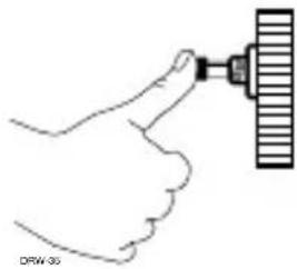
To disable the optional Failsafe Starter Kill, turn the ignition to the ON position. Press and release the Valet switch one time within 10 seconds. The status LED will stop flashing and the vehicle should start. If the vehicle does not start, you may have waited too long; turn the ignition off and repeat the process.
natural_image
Illustration of a hand holding a tool with a ruler inserted, no text or symbols presentLocation of Valet Button
audible mode
This system is designed to work similar to some factory keyless entry systems and will not sound the horn when Locking/ Unlocking. The horn will honk when pressing the 🔒 button on the remote twice (for lock only) or you can temporarily turn on the arm or disarm horn honk(s) by simply pressing AUX for less than one second before locking or unlocking, and the confirmation honk(s) will be present for that one oper a tion only.
valet mode
You can prevent your system from automatically activating the Failsafe® Starter Kill (optional, not included) and locking the doors by using Valet® Mode. This is very useful when washing the vehicle or having it serviced. In Valet® Mode, the starter kill cannot be activated, even with the transmit ter, but all con ve nience functions (door locks, trunk release, etc.) will continue to work normally.
To enter or exit Valet® Mode:

- Turn the ignition on.
- Turn the ignition off.
- Press and release the Valet® switch within 10 seconds.

natural_image
Hand holding a tool with a ruler above it, no text or symbols visibleThe status LED will light steadily if you are entering Valet ^® Mode and will turn off if you are exiting Valet ^® Mode.
panic mode
If you are threatened in or near your vehicle, you can attract attention by triggering the system with your transmitter. Just press for two seconds to enter Panic Mode. In Panic Mode, the horn will honk and the parking lights will flash for 30 seconds. To stop Panic Mode at any time, press on the transmitter again.
note: In order for Panic Mode to be effective, the vehicle's horn (or optional siren) as well as the vehicle's parking lights must be connected.
rapid resume logic
This Directed system will store its current state to non-volatile memory. If power is lost and then reconnected, the system will recall the stored state from memory. This means if the unit is in Valet Mode and the battery is dis connected for any reason, such as servicing the car, when the battery is re connected the unit will still be in Valet Mode. This applies to all states of the system including arm, disarm, and panic mode.
programming options
Programming options control your system's normal, operational set-up. Most options do not require additional parts, but some may require additional installation labor. This system's programming options are listed below, with the factory default settings in bold:
- Ignition switch-controlled door-locking on or off. With this feature on, the doors will lock 3 seconds after the ignition key is turned on, and unlock when the ignition key is turned off.
- Comfort Closure off or on. This option is not available for all vehicles. When programmed on, and pressing 📄 on the remote, the vehicle will lock and close the windows/sunroof. See your dealer to see if this is available for your vehicle.
glossary of terms
Control Unit: The “brain” of your system. Usually hidden under the dash area of the vehicle. It houses the microprocessor that monitors your vehicle and controls all system functions.
LED: A light mounted at a discretionary location inside the vehicle. It is used to indicate the status of your system.
Failsafe Starter Kill: An automatic switch controlled by your system which prevents the vehicle's starter from cranking whenever the system is armed. The vehicle is never prevented from cranking when the system is disarmed, in Valet Mode, or if the starter interrupt switch itself fails. Your system has feature-ready circuitry for the starter interrupt, however installation may require additional labor.
Transmitter: A hand-held, remote control which operates the various functions of your system.
Valet Switch: A small button mounted at a discretionary location inside the vehicle. It is used to override the system when a transmitter is lost or damaged, or to enter or exit Valet Mode.
Listed below are some of the many expansion options available for use with your system. Some options may require additional parts and/or labor. Please consult with your dealer for a complete list of options available for use with this system.
Domelight Supervision: The domelight will illuminate for 30 seconds each time the system is disarmed using the remote. This is useful for seeing inside the vehicle at night prior to entering it.
Power Door Lock Control: Your system is capable of controlling many types of power door lock systems; however, some door lock systems may require extra parts. Consult with your dealer to determine which type of locks your vehicle uses. If power locks are connected, the system can be programmed to lock the doors automatically 30 seconds after the ignition has been turned off. The system can also be programmed to lock the doors when the ignition is turned on and to unlock them when the ignition is turned off.
Power Trunk Release: The system's auxiliary output can be programmed to operate a factory power release for the vehicle's trunk or hatch. If the factory release is not power-activated, Directed's 522T trunk-release solenoid can often be added.
Power Window Control: Power window control is provided with Directed's 529T or 535T systems. The 529T system will roll up two windows automatically when the system is armed, or roll two windows down by using the transmitter. The 535T will roll two windows both up and down. The 535T also provides one touch switch operation.
Progressive Door Unlocking: For added security, your system can be configured to unlock the driver's door only, leaving the passenger doors locked. Pressing the unlock button an additional time will unlock the passenger doors. This option requires additional parts and labor.
patent information
This product is covered by one or more of the following United States patents:
Remote Start Patents:
| 5,349,931; | 5,872,519; | 5,914,667; | 5,952,933; | 5,945,936; |
| 5,990,786; | 6,028,372; | 6,467,448; | 6,561,151; | 7,191,053; |
| 7,483,783; | 8,112,185 |
Vehicle Security Patents:
| 5,467,070; | 5,532,670; | 5,534,845; | 5,563,576; | 5,646,591; |
| 5,650,774; | 5,673,017; | 5,712,638; | 5,872,519; | 5,914,667; |
| 5,952,933; | 5,945,936; | 5,990,786; | 6,028,505; | 6,452,484; |
| 7,519,400; | 7,898,386 |
Other patents pending.




- Table of Contents
- Primary harness (H1), 18-pin connector
- Peripheral Plug-In Harnesses
- Super Bright LED, 2-Pin WHITE Plug
- Valet/Program Switch, 2-Pin BLUE Plug
- System Features Learn Routine
- System Features Menus
- Feature Descriptions
- Transmitter/Receiver Learn Routine
- Transmitter Configurations
- Standard Configuration
- Rapid Resume Logic
- Wiring Quick Reference Guide
- The company behind this system is Directed
- DIRECTED.
- Viper®
- limited lifetime consumer warranty
- limited lifetime consumer warranty....i
- standard transmitter configuration....4
- what is included....4
- important information ....5
- transmitter functions 6
- using your system 8
- rapid resume logic 12
- programming options....12
- glossary of terms....13
- patent information 16
- standard transmitter configuration
- what is included
- important information
- system maintenance
- your warranty
- fcc/id notice
- transmitter functions
- Button
- and
- Buttons
- locking/arming
- unlocking/disarming
- disabling the system without a transmitter
- Location of Valet Button
- audible mode
- valet mode
- To enter or exit Valet® Mode:
- panic mode
- programming options
- glossary of terms
- patent information
Brand : Viper
Model : 211HV
Category : Car alarm