
CR 13VC - Uncategorized HITACHI - Free user manual and instructions
Find the device manual for free CR 13VC HITACHI in PDF.

| Product Type | Reciprocating Saw (Sabre Saw) |
| Power Input | 1010 W |
| No-Load Speed | 0 – 2800 min⁻¹ (variable via trigger and dial) |
| Stroke Length | 29 mm |
| Cutting Capacity (Mild Steel Pipe) | Outer diameter 130 mm |
| Cutting Capacity (Vinyl Chloride Pipe) | Outer diameter 130 mm |
| Cutting Capacity (Wood) | Depth 300 mm |
| Cutting Capacity (Mild Steel Plate) | Thickness 19 mm |
| Weight (without cord) | 3.3 kg |
| Blade Change | Tool-less, lever-operated detachable mechanism |
| Speed Adjustment | Variable speed trigger and dial (6 positions: 1-5) |
| Base Adjustment | Adjustable with hexagonal bar wrench |
| Plunge Cutting | Possible with reverse blade installation (BI-METAL blade recommended) |
| Sound Pressure Level | 91 dB(A) |
| Vibration Acceleration | 16.8 m/s² (weighted RMS) |
| Standard Accessories | Blade No.103, carrying case, hexagonal bar wrench |
| Optional Accessories | Various HCS and BI-METAL blades for different materials |
| Power Source | AC (voltage varies by model; check nameplate) |
| Motor Type | Universal motor with carbon brushes (replaceable) |
| Safety Features | Lock-off switch (prevents accidental start), blade guard, safety instructions in manual |
| Maintenance | Clean sawdust from blade holder; lubricate periodically; inspect and replace carbon brushes |
Frequently Asked Questions - CR 13VC HITACHI
User questions about CR 13VC HITACHI
0 question about this device. Answer the ones you know or ask your own.
Ask a new question about this device
Download the instructions for your Uncategorized in PDF format for free! Find your manual CR 13VC - HITACHI and take your electronic device back in hand. On this page are published all the documents necessary for the use of your device. CR 13VC by HITACHI.
USER MANUAL CR 13VC HITACHI
natural_image
Line drawing of a mechanical tool with saw and handle (no text or symbols)Read through carefully and understand these instructions before use.

Bruksanvisning
Brugsanvisning
Bruksanvisning
Käyttöohjeet
Handling Instructions
1
2
3
4
5
6
7
8
9
10
natural_image
Diagram of a mechanical tool with a cutting tool and clamping mechanism (no text or symbols)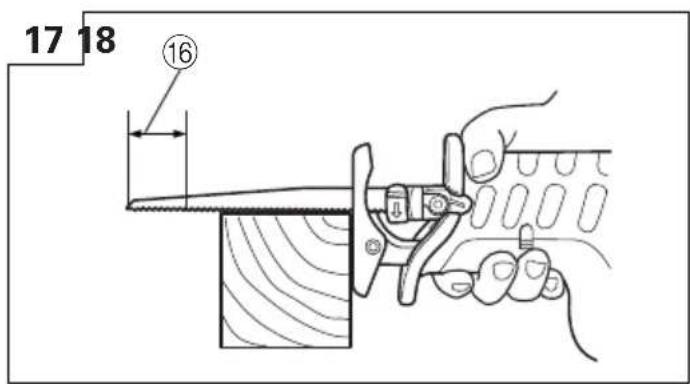
natural_image
Illustration of a hand using a tool to cut a wooden block, no text or symbols present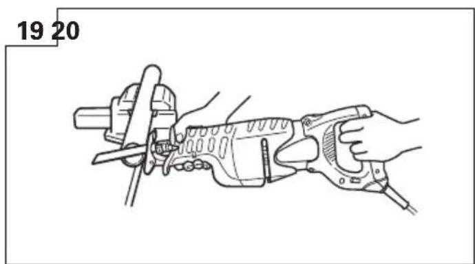
natural_image
Line drawing of a hand using a power tool to cut a saw (no text or symbols present)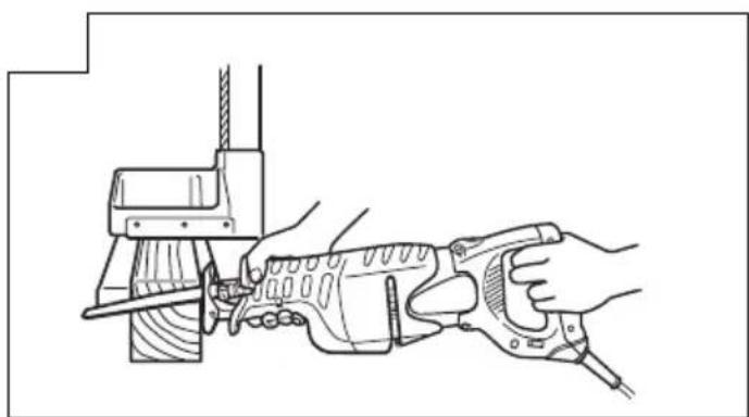
natural_image
Line drawing of a hand using a saw to cut a mechanical component (no text or symbols)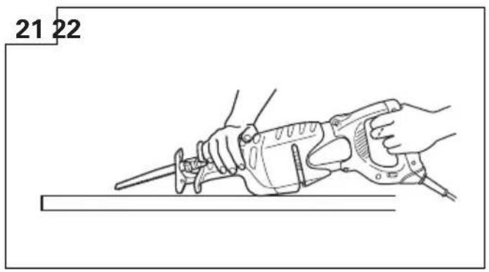
natural_image
Line drawing of a hand using a sawtooth tool to cut a flat surface, no text or symbols present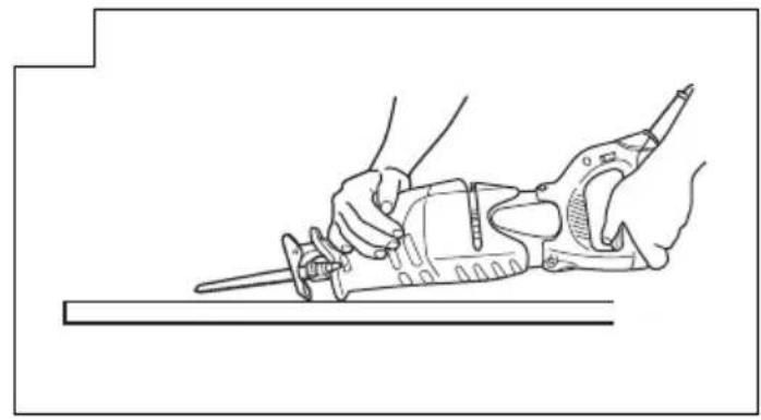
natural_image
Line drawing of hands using a sawdriver to cut a tool (no text or symbols present)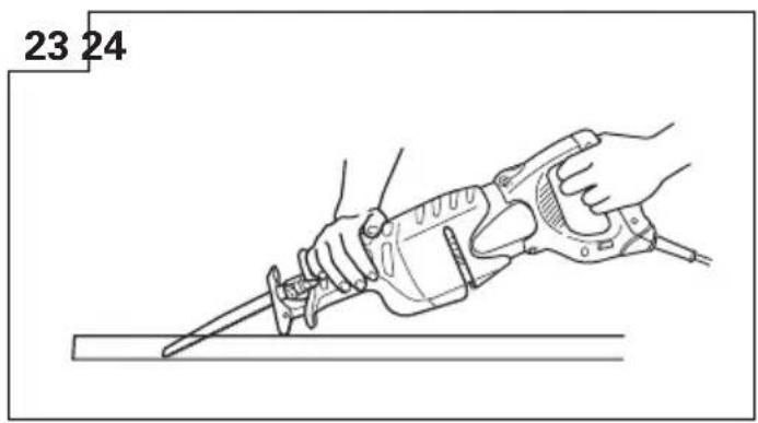
natural_image
Line drawing of a hand using a sawdriver to cut a tool, labeled with numbers 23 and 24 (no text or symbols on the diagram itself)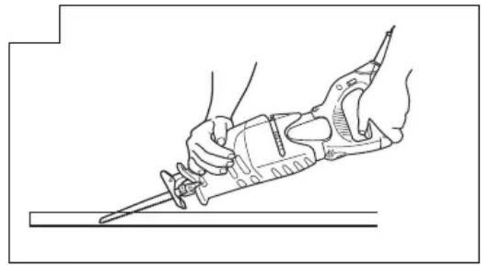
natural_image
Line drawing of a hand using a sawtooth tool to cut a surface (no text or symbols present)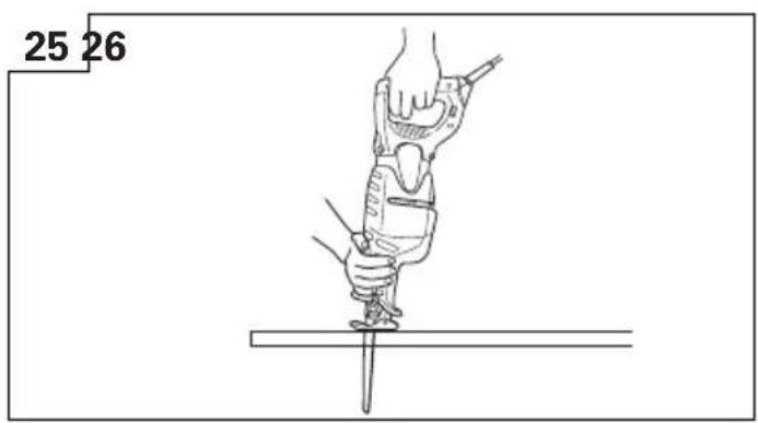
natural_image
Line drawing of a hand using a tool to lift or adjust a screwdriver (no text or symbols present)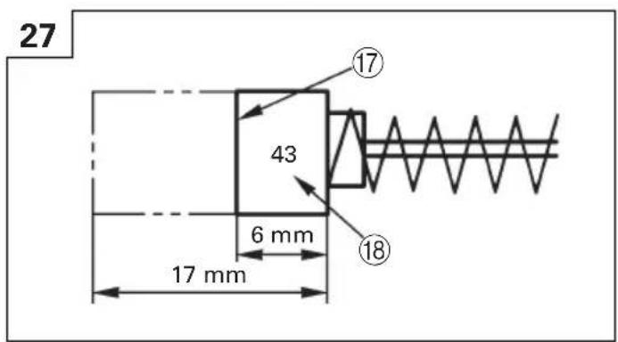
VEDLIKEHOLD OG INSPEKSJON AV SAGBLADETS MONTERING
VEDLIKEHOLD OG KONTROLL
1. Inspiser bladet
WARNING! When using electric tools, basic safety precautions should always be followed to reduce the risk of fire, electric shock and personal injury, including the following.
Read all these instructions before operating this product and save these instructions.
For safe operations:
- Keep work area clean. Cluttered areas and benches invite injuries.
- Consider work area environment. Do not expose power tools to rain. Do not use power tools in damp or wet locations. Keep work area well lit. Do not use power tools where there is risk to cause fire or explosion.
- Guard against electric shock. Avoid body contact with earthed or grounded surfaces. (e.g. pipes, radiators, ranges, refrigerators).
- Keep children away. Do not let visitors touch the tool or extension cord. All visitors should be kept away from work area.
- Store idle tools. When not in use, tools should be stored in a dry, high or locked up place, out of reach of children.
- Do not force the tool. It will do the job better and safer at the rate for which it was intended.
- Use the right tool. Do not force small tools or attachments to do the job of a heavy duty tool. Do not use tools for purposes not intended; for example, do not use circular saw to cut tree limbs or logs.
- Dress properly. Do not wear loose clothing or jewelry, they can be caught in moving parts. Rubber gloves and non-skid footwears are recommended when working outdoors. Wear protecting hair covering to contain long hair.
- Use eye protection. Also use face or dust mask if the cutting operation is dusty.
- Connect dust extraction equipment. If devices are provided for the connection of dust extraction and collection facilities ensure these are connected and properly used.
- Do not abuse the cord. Never carry the tool by the cord or yank it to disconnect it from the receptacle. Keep the cord away from heat, oil and sharp edges.
- Secure work. Use clamps or a vise to hold the work. It is safer than using your hand and it frees both hands to operate tool.
- Do not overreach. Keep proper footing and balance at all times.
- Maintain tools with care. Keep cutting tools sharp and clean for better and safer performance. Follow instructions for lubrication and changing accessories. Inspect tool cords periodically and if damaged, have it repaired by authorized service center. Inspect extension cords periodically and replace, if damaged. Keep handles dry, clean, and free from oil and grease.
-
Disconnect tools. When not in use, before servicing, and when changing accessories such as blades, bits and cutters.
-
Remove adjusting keys and wrenches. Form the habit of checking to see that keys and adjusting wrenches are removed from the tool before turning it on.
- Avoid unintentional starting. Do not carry a plugged-in tool with a finger on the switch. Ensure switch is off when plugging in.
- Use outdoor extension leads. When tool is used outdoors, use only extension cords intended for outdoor use.
- Stay alert. Watch what you are doing. Use common sense. Do not operate tool when you are tired.
- Check damaged parts. Before further use of the tool, a guard or other part that is damaged should be carefully checked to determine that it will operate properly and perform its intended function. Check for alignment of moving parts, free running of moving parts, breakage of parts, mounting and any other conditions that may affect its operation. A guard or other part that is damaged should be properly repaired or replaced by an authorized service center unless otherwise indicated in this handling instructions. Have defective switches replaced by an authorized service center. Do not use the tool if the switch does not turn it on and off.
- Warning The use of any accessory or attachment, other than those recommended in this handling instructions, may present a risk of personal injury.
- Have your tool repaired by a qualified person. This electric tool is in accordance with the relevant safety requirements. Repairs should only be carried out by qualified persons using original spare parts. Otherwise this may result in considerable danger to the user.
PRECAUTIONS ON USING RECIPROCATING SAW
Prior to cutting into walls, ceilings or floors, ensure there are no electric cables or conduits inside.
SPECIFICATIONS
| Voltage (by areas)* (110V, 115V, 120V, 127V, 220V, 230V, 240V) | |
| Power Input 1010 W* | |
| Capacity Mild Steel Pipe: O.D. 130 mm | Vinyl Chloride Pipe: O.D. 130 mmWood: Depth 300 mmMild Steel Plate: Thickness 19 mm |
| No-Load Speed 0 – 2800min | -1 |
| Stroke 29 mm | |
| Weight (without cord) 3.3 kg | |
* Be sure to check the nameplate on product as it is subject to change by areas.
STANDARD ACCESSORIES
(1) Blade (No. 103) .... 1
(2) Case 1
(3) Hexagonal bar wrench 1
Standard accessories are subject to change without notice.
OPTIONAL ACCESSORIES (sold separately)
| (1) No. 1 Blade (12) No. 103 Blade |
| (2) No. 2 Blade (13) No. 104 Blade |
| (3) No. 3 Blade (14) No. 105 Blade |
| (4) No. 4 Blade (15) No. 106 Blade |
| (5) No. 5 Blade (16) No. 107 Blade |
| (6) No. 8 Blade (17) No. 108 Blade |
| (7) No. 9 Blade (18) No. 121 Blade |
| (8) No. 95 Blade (19) No. 131 Blade |
| (9) No. 96 Blade (20) No. 132 Blade |
| (10) No. 101 Blade (21) Cut-off guide for pipe |
| (11) No. 102 Blade |
○(1) - (9) : HCS Blades (HCS : Highspeed Carbon Steel)
○(10) - (20) : BI-METAL Blades
Refer to Table 1, 2 and 3 for use of the blades.
Optional accessories are subject to change without notice.
APPLICATIONS
○Cutting pipe and angle steel.
○Cutting various lumbers.
○Cutting mild steel plates, aluminum plates, and copper plates.
○Cutting synthetic resins, such as phenol resin and vinyl chloride.
For details refer to the section entitled "SELECTION OF BLADES".
PRIOR TO OPERATION
1. Power source
Ensure that the power source to be utilized conforms to the power requirement specified on the product nameplate.
2. Power switch
Ensure that the power switch is in the OFF position.
If the plug is connected to a receptacle while the power switch is in the ON position, the power tool will start operating immediately, which could cause a serious accident.
3. Extension cord
When the work area is removed from the power source, use an extension cord of sufficient thickness and rated capacity. The extension cord should be kept as short as practicable.
4. Mounting the blade
This unit employs a detachable mechanism that enables mounting and removal of saw blades without the use of a wrench or other tools.
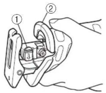
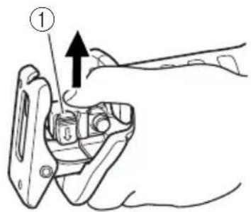
(1) Turn on and off the switching trigger several times so that the lever can jump out of the front cover completely. Thereafter, turn off the switch and unplug the power cord. (Fig. 1)
CAUTION
Be absolutely sure to keep the switch turned off and the power cord unplugged to prevent any accident.
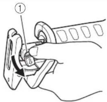
(2) Push the lever in the direction of the arrow mark shown in Fig. 2 marked on the lever. (Fig. 2)
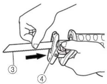
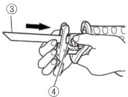
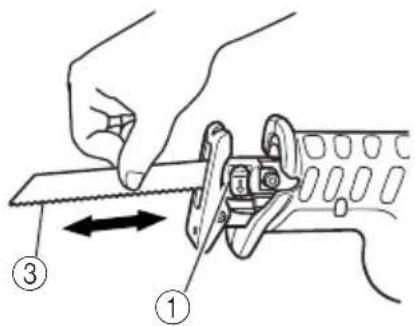
(3) Insert the saw blade all the way into the small slit of the plunger tip with the lever pushing. You can mount this blade either in the upward or downward direction. (Fig. 3, Fig. 4)
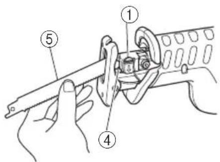
(4) When you release the lever, the spring force will return the holder sleeve to the correct position automatically. (Fig. 5)
(5) Pull the back of the saw blade two or three times by hand and check that the blade is securely mounted. When pulling the blade, you will know it is properly mounted if it clicks and the lever moves slightly. (Fig. 6)
CAUTION
When pulling the saw blade, be absolutely sure to pull it from the back. Pulling other parts of the blade will result in an injury.
5. Dismounting the blade
(1) Turn on and off the switching trigger several times so that the lever can jump out of the front cover completely. Thereafter, turn off the switch and unplug the power cord. (Fig. 1)
CAUTION
Be absolutely sure to keep the switch turned off and the power cord unplugged to prevent any accident.
(2) After you have pushed the lever in the direction of the arrow mark shown in Fig. 2, turn the blade so it faces downward. The blade should fall out by itself. If the blade doesn't fall out, pull it out by hand.
CAUTION
Never touch the saw blade immediately after use. The metal is hot and can easily burn your skin.
WHEN THE BLADE IS BROKEN
Even when the saw blade is broken and remains inside the small slit of the plunger, it should fall out if you push the lever in the direction of the arrow mark, and face the blade downward. If it doesn't fall out itself, take it out using the procedures explained below.
(1) If a part of the broken saw blade is sticking out of the small slit of the plunger, pull out the protruding part and take the blade out.
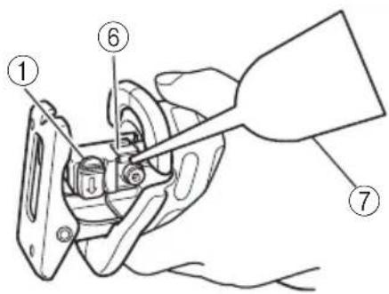
(2) If the broken saw blade is hidden inside the small slit, hook the broken blade using a tip of another saw blade and take it out. (Fig. 7)
MAINTENANCE AND INSPECTION OF SAW BLADE MOUNT
(1) After use, blow away sawdust, earth, sand, moisture, etc., with air or brush them away with a brush, etc., to ensure that the blade mount can function smoothly.
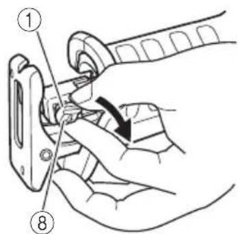
(2) As shown in Fig. 8, carry out lubrication around the blade holder on a periodic basis by use of cutting fluid, etc.
NOTE:
Continued use of the tool without cleaning and lubricating the area where the saw blade is installed can result in some slack movement of the lever due to accumulated sawdust and chips. Under the circumstances, pull a rubber cap provided on the lever in the direction of an arrow mark as shown in Fig. 9 and remove the rubber cap from the lever. Then, clean up the inside of the blade holder with air and the like and carry out sufficient lubrication. The rubber cap can be fitted on if it is pressed firmly onto the lever. At this time, make certain that there exists no clearance between the blade holder and the rubber cap, and furthermore ensure that the saw-blade-installed area can function smoothly.
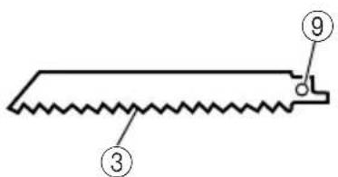
CAUTION:
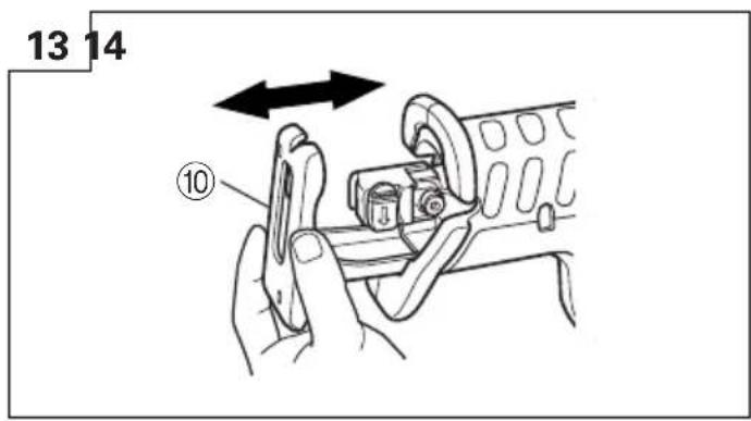
Do not use any saw blade with a worn-out blade hole. Otherwise, the saw blade can come off, resulting in personal injury. (Fig. 10)
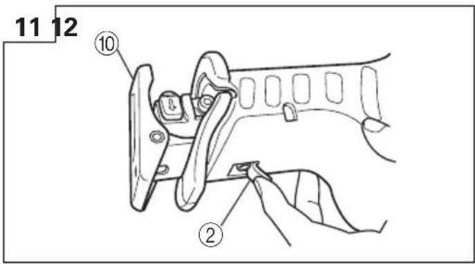
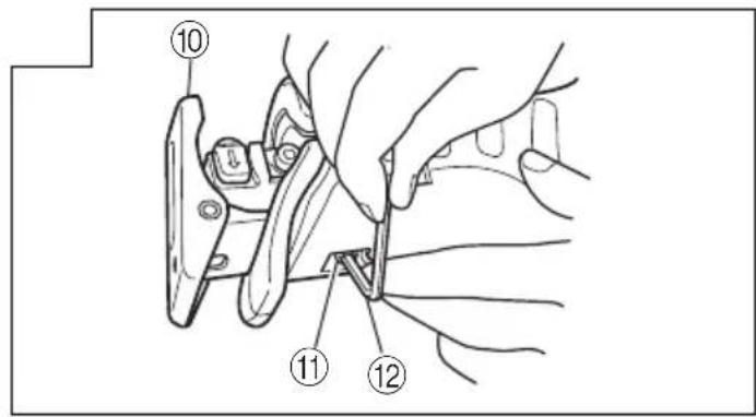
6. Adjusting the base
(1) Lift the front cover up as illustrated in Fig. 11.
(2) If a base setting screw is loosened with an attached hexagonal bar wrench, you can adjust a base installing position. (Fig. 12, Fig. 13)
(3) After adjusting the base installing position, tighten the base setting screw with the attached hexagonal bar wrench completely.
7. Adjusting the blade reciprocating speed
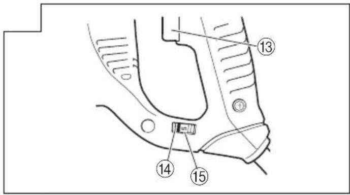
This unit has a built-in electronic control circuit that makes it possible to adjust the variable speed of the saw blade either both by pulling a switching trigger or turning a dial. (Fig. 14)
(1) If you pull the trigger further in, the speed of the blade accelerates. Begin cutting at a low speed to
ensure the accuracy of your target cut position. Once you've obtained a sufficient cutting depth, increase the cutting speed.
(2) On the dial scale, "5" is the maximum speed and "1" the minimum. The high speed is generally suitable for soft materials such as wood, and the low speed is suitable for hard materials such as metal. We recommend that you use the following as a rough guide in selecting the suitable speed for the materials you are cutting.
| Example of materials Recommended to be cut dial scale | |
| Mild steel pipes / cast-iron tubes / 2 – 4 L-shaped angle steel | |
| Wood / wood with nails driven in | 5 |
| Stainless steel 1 – 3 | |
| Aluminum / brass / copper 2 – 4 | |
| Plaster board 4 – 5 | |
| Plastic / fiber board 1 – 3 |
CAUTION
○When cutting at low speed (scale of 1 – 2), never cut a wooden board more than 10 mm thick or a mild steel plate more than 2 mm thick. The load on the motor can result in overheating and damage.
Although this unit employs a powerful motor, prolonged use at a low speed will increase the load unduly and may lead to overheating. Properly adjust the saw blade to allow steady, smooth cutting operation, avoiding any unreasonable use such as sudden stops during cutting operation.
HOW TO USE
CAUTION
○Avoid carrying it plugged to the outlet with your finger on the switch. A sudden startup can result in an unexpected injury.
○Be careful not to let sawdust, earth, moisture, etc., enter the inside of the machine through the plunger section during operation. If sawdust and the like accumulate in the plunger section, always clean it before use.
○ Do not remove the front cover (refer to Fig. 1). Be sure to hold the body from the top of the front cover.
○During use, press the base against the material while cutting.
Vibration can damage the saw blade if the base is not pressed firmly against the workpiece.
Furthermore, a tip of the saw blade can sometimes contact the inner wall of the pipe, damaging the saw blade.
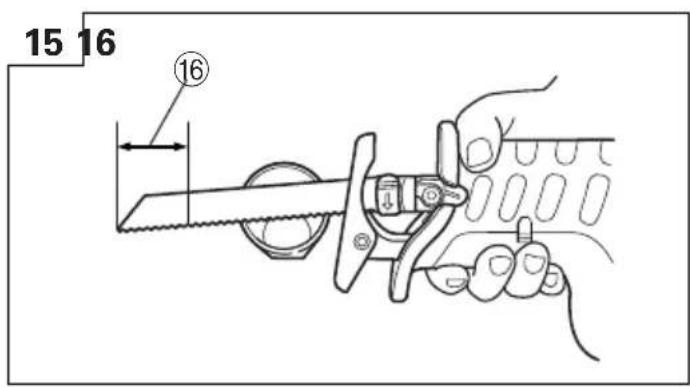
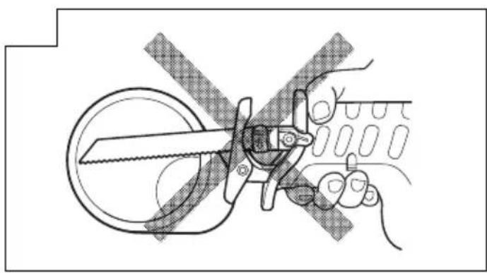
○Select a saw blade of the most appropriate length. Ideally, the length protruding from the base of the saw blade after subtracting the stroke quantity should be larger than the material (see Fig. 15 and Fig. 17).
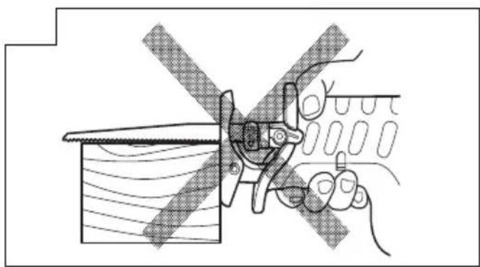
If you cut a large pipe, large block of wood, etc., that exceeds the cutting capacity of a blade; there
is a risk that the blade may contact with the inner wall of the pipe, wood, etc., resulting in damage. (Fig. 16, Fig. 18)
To maximize cutting efficiency for the materials you are using and working conditions, adjust the speed of the saw blade.
1. Cutting metallic materials CAUTION
○Press the base firmly against the workpiece.
Never apply any unreasonable force to the saw blade when cutting. Doing so can easily break the blade.
(1) Fasten a workpiece firmly before operation. (Fig. 19)
(2) When cutting metallic materials, use proper machine oil (turbine oil, etc.). When not using liquid machine oil, apply grease over the workpiece.
CAUTION
The service life of the saw blade will be drastically shortened if you don't use machine oil.
(3) Use the dial to adjust the speed of the saw blade to suit your working conditions and materials.
2. Cutting lumber
(1) When cutting lumber, make sure that the workpiece is fastened firmly before beginning. (Fig. 20)
(2) You can cut efficiently if the speed of the saw blade is set to dial scale "5".
CAUTION
Never apply any unreasonable force to the saw blade when cutting. Also remember to press the base against the lumber firmly.
3. Sawing curved lines
We recommend that you use the BI-METAL blade mentioned in Table 2 (Page 31) for the saw blade since it is tough and hardly breaks.
CAUTION
Delay the feed speed when cutting the material into small circular arcs. An unreasonably fast feed may break the blade.
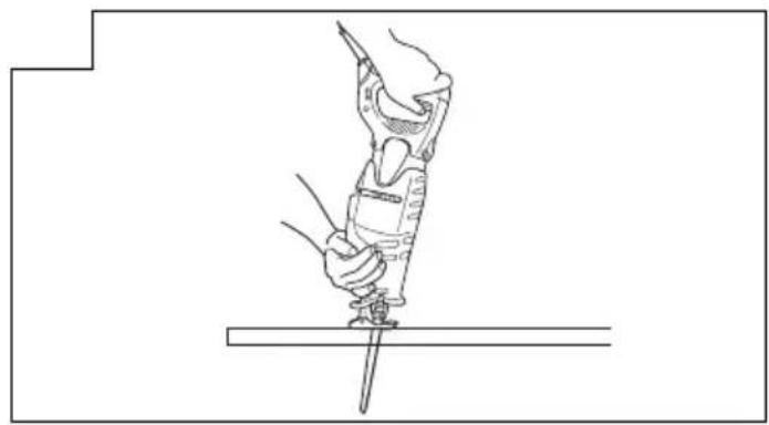
4. Plunge cutting
With this tool, you can perform plunge cutting on plywood panels and thin board materials. You can carry out pocket cutting quite easily with the saw blade installed in reverse as illustrated in Fig. 22,
Fig. 24, and Fig. 26. Use the saw blade that is as short and thick as possible. We recommend for this purpose that you use BI-METAL Blade No. 132 mentioned in Page 31, Table 2. Be sure to use caution during the cutting operation and observe the following procedures.
(1) Press the lower part (or the upper part) of the base against the material. Pull the switch trigger while keeping the tip of the saw blade apart from the material. (Fig. 21, Fig. 22)
(2) Raise the handle slowly and cut in with the saw blade little by little. (Fig. 23, Fig. 24)
(3) Hold the body firmly until the saw blade completely cuts into the material. (Fig. 25, Fig. 26)
CAUTION
○Avoid plunge cutting for metallic materials. This can easily damage the blade.
Never pull the switch trigger while the tip of the saw blade tip is pressed against the material. If you do so, the blade can easily be damaged when it collides with the material.
○Make absolutely sure that you cut slowly while holding the body firmly. If you apply any
unreasonable force to the saw blade during the cutting operation, the blade can easily be damaged.
5. Cut off guide for cutting pipe (optional accessory)
| Product | Cutting Blade application used | Code No. | |
| Cut-off Outer diameter guide (L) 75mm - 165mm | No. 9 32 | 1113 | |
NOTE
Please refer to the cut off guide user's manual for details on how to use ti correctly.
SELECTION OF BLADES
To ensure maximum operating efficiency and results, it is very important to select the appropriate blade best suited to the type and thickness of the material to be cut. NOTE:
○Dimensions of the workpiece mentioned in the table represent the dimensions when the mounting position of the base is set nearest to the body of the saber saw. Caution must be exercised since dimensions of the workpiece will become smaller if the base is mounted far away from the body of the saber saw.
1. Selection of HCS blades
The blade number of HCS blades in Table 1 is engraved in the vicinity of the mounting position of each blade. Select appropriate blades by referring to Tables 1 and 3 below.
Table 1: HCS blades
| Blade No. | Thickness Uses | (mm) |
| No. 1 | For cutting steel pipe less than 105 mm in diameter | 2.5 – 6 |
| No. 2 | For cutting steel pipe less than 30 mm in diameter | 2.5 – 6 |
| No. 3 | For cutting steel pipe less than 30 mm in diameter | Below 3.5 |
| No. 4 | For cutting and roughing lumber 50 – 70 | |
| No. 5 | For cutting and roughing lumber Below 30 | |
| No. 8 | For cutting vinyl chloride pipe less than 105 mm in diameter | 2.5 – 15 |
| For cutting and roughing lumber Below 105 | ||
| No. 9 | For cutting mild steel pipe less than 165 mm in diameter when 2.5 – 6 used with cut off guide | |
| No. 95 | For cutting stainless steel pipe less than 105 mm in diameter | Below 2.5 |
| No. 96 | For cutting stainless steel pipe less than 30 mm in diameter | Below 2.5 |
NOTE
No. 1 – No. 96 HCS blades are sold separately as optional accessories.
2. Selection of BI-METAL blades
The BI-METAL blade numbers in Table 2 are described on the packages of special accessories. Select appropriate blades by referring to Table 2 and 3 below.
Table 2: BI-METAL blades
| Blade No. | Thickness Uses | (mm) |
| No. 101 | For cutting steel and stainless pipes less than 60 mm in outer diameter | 2.5 – 6 |
| No. 102 | For cutting steel and stainless pipes less than 130 mm in outer diameter | 2.5 – 6 |
| No. 103 | For cutting steel and stainless pipes less than 60 mm in outer diameter | 2.5 – 6 |
| No. 104 | For cutting steel and stainless pipes less than 130 mm in outer diameter | 2.5 – 6 |
| No. 105 | For cutting steel and stainless pipes less than 60 mm in outer diameter | 2.5 – 6 |
| No. 106 | For cutting steel and stainless pipes less than 130 mm in outer diameter | 2.5 – 6 |
| No. 107 | For cutting steel and stainless pipes less than 60 mm in outer diameter | Below 3.5 |
| No. 108 | For cutting steel and stainless pipes less than 130 mm in outer diameter | Below 3.5 |
| No. 121 | For cutting and roughing lumber 300 | |
| No. 131 | All purposes — | |
| No. 132 | All purposes — |
NOTE
Nos. 101 – No. 132 BI-METAL blades are sold separately as optional accessories.
3. Selection of blades for other materials
Table 3
| Material Material Thickness to be cut quality (mm) | Blade No. | ||
| Iron plate M | Mild steel 2.5 – 19 plate | No. 1, 2, | 101, 102, 103, 104, 105, 106, 131, 132 |
| Below 3.5 | No. 3, 107, 108 | ||
| Nonferrous metal | Aluminium, Copper and Brass | 5 – 20 No. | 1, 2, 101, 102, 103, 104, 105, 106, 131, 132 |
| Below 5 | No. 3, 107, 108 | ||
| Systhetic Ph resin | enol resin, 10 – Melamine resin, etc. | 50 No. 1, 2, | 4, 101, 102, 103, 104, 131, 132 |
| 5 – 30 No. | 3, 5, 8, 105, 106, 107, 108 | ||
| Material M to be cut quality (mm) | Blade No. | ||
| Systhetic | Vinyl chloride, Acrylic resin, etc. 104, 131, 132 | 10 – 60 No. 1, 2, 4, 101, 102, 103, 132 | |
| 5 – 30 No. 3, 5, 8, 105, 106, 107, 108 | |||
MAINTENANCE AND INSPECTION
1. Inspecting the blade
Continued use of a dull or damaged blade will result in reduced cutting efficiency and may cause overloading of the motor. Replace the blade with a new one as soon as excessive abrasion is noted.
2. Inspecting the mounting screws:
Regularly inspect all mounting screws and ensure that they are properly tightened. Should any of the screws be loose, retighten them immediately. Failure to do so could result in serious hazard.
3. Maintenance of the motor
The motor unit winding is the very "heart" of the power tool. Exercise due care to ensure the winding does not become damaged and/or wet with oil or water.
4. Inspecting the carbon brushes (Fig. 27)
The Motor employs carbon brushes which are consumable parts. When they become worn to or near the "wear limit", it could result in motor trouble. When an auto-stop carbon brush is equipped, the motor will stop automatically.
At that time, replace both carbon brushes with new ones which have the same carbon brush Numbers shown in the figure. In addition, always keep carbon brushes clean and ensure that they slide freely within the brush holders.
5. Replacing carbon brushes:
Disassemble the brush caps with a slotted-head screwdriver. The carbon brushes can then be easily removed.
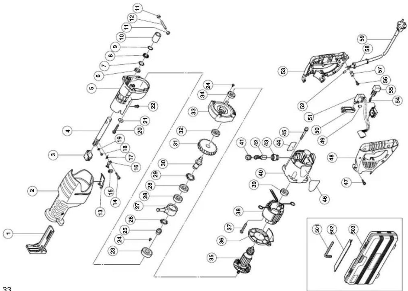
6. Service parts list
A: Item No.
B: Code No.
C: No. Used
D: Remarks
CAUTION
Repair, modification and inspection of Hitachi Power Tools must be carried out by an Hitachi Authorized Service Center.
This Parts List will be helpful it presented with the tool to the Hitachi Authorized Serivde Center when requesting repair or other maintenance.
In the operation and maintenance of power tools, the safety regulations and standards prescribed in each country must be observed.
MODIFICATIONS:
Hitachi Power Tools are constantly being improved and modified to incorporate the latest technological advancements.
Accordingly, some parts (i.e. code numbers and/or design) may be changed without prior notice.
NOTE
Due to HITACHI's continuing program of research and development, the specifications herein are subject to change without prior notice.
Information concerning airborne noise and vibration The measured values were determined according to EN50144.
The typical A-weighted sound pressure level: 91 dB (A) The typical A-weighted sound power level: 104 dB (A) Wear ear protection.
The typical weighted root mean square acceleration value: 16.8 m/s ^2
| A | B | C | D |
| 39 | 608-VVM 1 | 608VVC2PS2L | |
| 40 | 318-506 | 1 | |
| 41 | 945-161 | 2 | |
| 42 | 999-043 | 2 | |
| 43 | 958-900 | 2 | |
| 44 | — — — — | 1 | |
| 45 | 307-224 | 4 M5×60 | |
| 46 | — — — — | 1 | |
| 47 | 307-028 | 5 D4×25 | |
| 48 | 321-140 | 1 | |
| 49 | 981-373 | 2 | |
| 51 | 318-505 | 1 | |
| 50 | 318-499 | 1 | |
| 52 | 981-373 | 2 | |
| 53 | 321-139 | 1 | |
| 54 | 938-108 | 1 | |
| 55 | 994-273 | 1 | |
| 56 | 984-750 | 2 D4×16 | |
| 57 | 937-631 | 1 | |
| 58 | 953-327 | 1 D8.8 | |
| 59 | 500-247Z | 1 | |
| 501 | 944-458 | 1 4MM | |
| 502 | 318-613 | 1 | |
| 503 | 321-142 | 1 |
| A | B | C | D |
| 1 321-116 | 1 | ||
| 2 321-125 | 1 | ||
| 3 321-132 | 1 | ||
| 4 321-120 | 1 | ||
| 5 321-123 | 1 | ||
| 6 318-458 | 1 | ||
| 7 321-117 | 1 | ||
| 8 318-459 | 1 | ||
| 9 321-118 | 1 | ||
| 10 C415795 | 1 | ||
| 11 321-126 | 2 | ||
| 12 318-491 | 1 D6 | ||
| 13 321-126 | 1 | ||
| 14 321-133 | 1 M4 | ||
| 15 321-130 | 1 | ||
| 16 321-131 | 1 | ||
| 17 321-135 | 1 | ||
| 18 321-134 | 1 | ||
| 19 318-483 | 1 | ||
| 20 318-451 | 1 M6×35 | ||
| 21 318-452 | 1 | ||
| 22 996-399 | 1 M5×12 | ||
| 23 600-2DD | 1 6002DDCMPS2L | ||
| 24 314-430 | 5 M4×10 | ||
| 25 321-129 | 1 | ||
| 26 967-261 | 1 | ||
| 27 321-121 | 1 | ||
| 28 600-3VV | 2 6003VVCMPS2L | ||
| 29 939-556 | 1 | ||
| 30 321-128 | 1 | ||
| 31 321-127 | 1 | ||
| 32 608-VVM | 1 608VVC2PS2L | ||
| 33 321-124 | 1 | ||
| 34 600-1VV | 1 6001VVCMPS2L | ||
| 35 360-581E | 1 220V-230V | ||
| 36 321-122 | 1 | ||
| 37 961-501 | 2 D5×60 | ||
| 38 340-479J | 1 220V-230V "37" |
natural_image
Line drawing of a quill pen in an inkwell (no text or symbols)
natural_image
Line drawing of a quill pen with inkwell (no text or symbols)
natural_image
Line drawing of a quill pen with inkwell (no text or symbols)| Svenska | Suomi | ||
| EF-DEKLARATION BETRÄFFANDE LIKFORMIGHETVi tillkännagiver med eget ansvar att denna produkt överensstämmer med standard eller standardiserat dokument EN50144, HD400, EN55014-1, EN55014-2, EN61000-3-2, EN61000-3-3 och/eller EN61000-3-11 i enlighet med råddirektiven 73/23/E∅S, 89/336/E∅S och/eller 98/37/EF.Denna deklaration gäller för CE-märkningen på produkten. | EY-ILMOITUS YHDENMUKAISUUDESTAYksinomaisella vastuudella vakuutamme, että tämä tuote vastaa normeja tai normitettuja dokumentteja EN50144, HD400, EN55014-1, EN55014-2, EN61000-3-2, EN61000-3-3 ja/tai EN61000-3-11 yhteisön ohjeiden 73/23/ETY, 89/336/ETY ja/tai 98/37/EY mukaisesti.Tämä ilmoitus sovelletaan tuotekohtaiseen CE-merkintään. | ||
| Dansk | English | ||
| EF-DEKLARATION OM ENSARTETHEDVi erlkærer os fuldstændige ansvarlige for, at dette produkt modsvarer gældende standard eller de standardiserede dokumenter EN50144, HD400, EN55014-1, EN55014-2, EN61000-3-2, EN61000-3-3 og/eller EN61000-3-11 i overensstemmelse med EF-direktiver 73/23/E∅F, 89/336/E∅S og/eller 98/37/EF.Denne erklæring gælder produkter, der er mærket med CE. | EC DECLARATION OF CONFORMITYWe declare under our sole responsibility that this product is in conformity with standards or standardized documents EN50144, HD400, EN55014-1, EN55014-2, EN61000-3-2, EN61000-3-3 and/or EN61000-3-11 in accordance with Council Directives 73/23/EEC, 89/336/EEC and/or 98/37/EC.This declaration is applicable to the product affixed CE marking. | ||
| Norsk | |||
| EF'S ERKLÆRING OM OVERENSSTEMMELSEVierklærerherved at vi påtar oss eneansvaret for at dette produktet er i overensstermmelse med normer eller standardiserte dokumenter EN 50144, HD400, EN55014-1, EN55014-2, EN61000-3-2, EN61000-3-3 og/eller EN61000-3-11 i samsvar med Rådsdirektiver 73/23/E∅S, 89/336/E∅S og/eller 98/37/EF.Denne erklæringen gjelder produktets påklistrede CE-merking. | |||
| Hitachi Power Tools Europe GmbHSiemensring 34, 47877 Willich, F. R. Germany Hitachi Koki Co., Ltd.Shinagawa Intercity Tower A, 15-1, Konan 2-chome, Minato-ku, Tokyo, Japan | |||
Hitachi Koki Co., Ltd.
- VEDLIKEHOLD OG INSPEKSJON AV SAGBLADETS MONTERING
- VEDLIKEHOLD OG KONTROLL
- Inspiser bladet
- PRECAUTIONS ON USING RECIPROCATING SAW
- STANDARD ACCESSORIES
- APPLICATIONS
- PRIOR TO OPERATION
- Power source
- Power switch
- Extension cord
- Mounting the blade
- CAUTION
- Dismounting the blade
- WHEN THE BLADE IS BROKEN
- MAINTENANCE AND INSPECTION OF SAW BLADE MOUNT
- NOTE:
- CAUTION:
- Adjusting the base
- Adjusting the blade reciprocating speed
- HOW TO USE
- Cutting metallic materials CAUTION
- Cutting lumber
- Sawing curved lines
- Plunge cutting
- Cut off guide for cutting pipe (optional accessory)
- NOTE
- SELECTION OF BLADES
- Selection of HCS blades
- Selection of BI-METAL blades
- Selection of blades for other materials
- MAINTENANCE AND INSPECTION
- Inspecting the blade
- Inspecting the mounting screws:
- Maintenance of the motor
- Inspecting the carbon brushes (Fig. 27)
- Replacing carbon brushes:
- Service parts list
- MODIFICATIONS:
- Hitachi Koki Co., Ltd.
Brand : HITACHI
Model : CR 13VC
Category : Uncategorized