
PAW-DHWM300ZE - Air-conditioner PANASONIC - Free user manual and instructions
Find the device manual for free PAW-DHWM300ZE PANASONIC in PDF.


| Product Type | Heat Pump Water Heater (Air-to-Water) |
| Model | PAW-DHWM300ZE |
| Tank Volume | 280 L |
| Weight (empty) | 166 kg |
| Weight (filled) | 446 kg |
| Rated Pressure | Up to 1.0 MPa (10 bar) |
| Insulation Thickness | 57 mm |
| Degree of Protection | IP21 |
| Max Connected Load | 620 W |
| Voltage | 230 V / 50 Hz |
| Adjusted Water Temperature | 55 °C (adjustable) |
| Legionella Control Temperature | 65 °C |
| Operation Air Temperature Range | 7 °C to 35 °C |
| Max Volumetric Air Flow | 480 m³/h |
| Refrigerant | R134a, 780 g |
| Sound Power Level | 56.7 dB(A) |
| Sound Pressure at 1 m | 44 dB(A) |
| Heating Time (A7/W10-55) | 11 h 10 min |
| COP (A7/W10-55) | 2.8 |
| Max Usable Water (min 40 °C) | 345.76 L |
| Cold Water Inlet Connection | G 3/4 |
| Hot Water Outlet Connection | G 1 |
| Tank Material | Enameled steel with MG anode |
| Anti-corrosion Protection | Sacrificial magnesium anode |
Frequently Asked Questions - PAW-DHWM300ZE PANASONIC
User questions about PAW-DHWM300ZE PANASONIC
0 question about this device. Answer the ones you know or ask your own.
Ask a new question about this device
Download the instructions for your Air-conditioner in PDF format for free! Find your manual PAW-DHWM300ZE - PANASONIC and take your electronic device back in hand. On this page are published all the documents necessary for the use of your device. PAW-DHWM300ZE by PANASONIC.
USER MANUAL PAW-DHWM300ZE PANASONIC
Installation Instructions, Operating Instructions, Spare Parts List
Water Tank with Heat Pump
natural_image
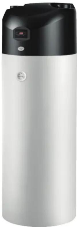
Exterior view of a silver and black industrial water heater (no visible text or symbols)Model No.
PAW-DHWM200ZC
PAW-DHWM300ZC
PAW-DHWM300ZE

Instructions for Use 3

Dear customer, thank you for purchasing our product.
PLEASE READ THE INSTRUCTIONS CAREFULLY PRIOR TO THE INSTALLATION AND FIRST USE OF THE HOT WATER TANK WITH HEATING PUMP.
THIS APPLIANCE IS NOT INTENDED FOR USE BY PERSONS (INCLUDING CHILDREN) WITH REDUCED PHYSICAL, SENSORY OR MENTAL CAPABILITIES, OR LACK OF EXPERIENCE AND KNOWLEDGE, UNLESS THEY HAVE BEEN GIVEN SUPERVISION OR INSTRUCTION CONCERNING USE OF THE APPLIANCE BY PERSON RESPONSIBLE FOR THEIR SAFETY.
CHILDREN SHOULD BE SUPERVISED TO ENSURE THAT THEY DO NOT PLAY WITH THE APPLIANCE.
The hot water tank with heating pump has been manufactured in accordance with the valid standards allowing the producer to use the CE mark. Basic technical characteristics of the product are listed on the label attached to the protective cover.
The installation of the hot water tank with heating pump must be carried out by qualified staff only. All repairs and maintenance work in the interior of the water heater as well as limestone removal or testing or replacement of the corrosion protection anode may only be carried out by an approved maintenance service provider. Please take into account instructions for safe operation and measures in case of malfunctions.
The water heater has been manufactured so as to allow alternative sources of energy besides electricity to be used, as follows:
- central heating hot - water system
- solar power
- electric heating element
This version of heating pump is used for heating the consumption water for households and other consumers, where daily consumption of hot water (50 °C) never exceeds 400 to 700 l. During the operation of the heating pump the temperature of the ambient air is reduced, hence the double effect of the heating pump: heating of hot water - cooling of the room. The operation of the heating pump is fully automated.
The heating pump is not intended for industrial use and use in premises where corrosive and explosive substances are present.
Always transport the heating pump in an upright position; exceptionally, it may be tilted by 35^ in all directions.
TECHNICAL CHARACTERISTICS THE HOT WATER TANK WITH HEATING PUMP
| Model PAW- | DHWM200ZC | PAW-DHWM300ZC | PAW-DHWM300ZE | |
| Volume | [l] | 200 | 285 | 280 |
| Rated pressure [MPa] up to 1,0 (10) | ||||
| Weight / Filled with water | [kg] | 120 / 320 | 149 / 434 | 166 / 446 |
| Anti-corrosion protection of tank | Enameled / MG Anode | |||
| HE heated surface - lower [m2] | 1,05 1,60 1,60 | |||
| HE heated surface - upper [m2] | - | - | 1,09 | |
| HE volume - lower | [l] | 6,6 | 10 | 10 |
| HE volume - upper | [l] | - | - | 6,8 |
| Heating power of HE - lower 1) | [kW] | 25,8 | 42,7 | 42,7 |
| Heating power of HE - upper 1) | [kW] | - | - | 26,9 |
| Temperature of the heating medium in HE | [°C] | 5 to 85 | ||
| Insulation thickness | [mm] | 57 | ||
| Degree of protection | IP 21 | |||
| Max connected load | [W] | 620 | ||
| Voltage | 230 V / 50 Hz | |||
| Adjusted water temperature | [°C] | 55 | ||
| Legionella control programme | [°C] | 65 | ||
| Operation zone - air | [°C] | 7 to 35 | ||
| Max volumetric flow rate of air | [m3/h] | 480 | ||
| Max acceptable pressure drop in the pipeline (volumetric flow rate of air 480 m3/h) | [Pa] | 90 | ||
| Refrigerating agent | R 134a | |||
| Quantity of coolant | [g] | 780 | ||
| *Heating time A7 / W10-55 | [h:min] | 7:22 | 11:10 | 11:10 |
| *Energy consumption during heating A7 / W10-55 [kWh] | 3,25 | 4,76 | 4,76 | |
| Type of measured cycle of emissions | L | XL | XL | |
| *Energy consumption in the selected cycle of emissions A7/W10-55 | [kWh] | 4,9 7,26 | 7,26 | |
| *COPDHW in the selected cycle of emissions A7 / W10-55 | 2,6 | 2,8 | 2,8 | |
| Max quantity of usable water (min 40 °C) | [l] | 252,08 | 345,76 | 345,76 |
| Sound power / Sound pressure at 1m | [dB(A)] | 56,7 / 44 | 56,7 / 44 | 56,7 / 44 |
HE - Heat exchanger
1) Heating of domestic water from 10 °C to 45 °C with the inlet temperature of the heating medium of 80 °C and flowrate of 3000 l/h.
(*) Heating of water to 55 °C at inlet air temperature of 7 °C, 89% humidity and inlet temperature of water of 10 °C; in accordance with the EN16147 standard.
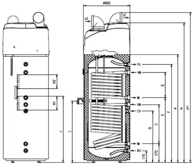
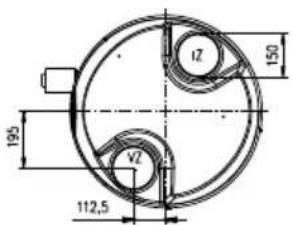
View from above
| TC 200-1/Z | TC 300-1/Z | TC 300-2/Z | |
| A | 1150 1550 | 1550 | |
| B | 740 740 740 | ||
| C | 380 560 560 | ||
| D | - | 930 | |
| E | -- | 360 | |
| F | 1010 | 1410 | 1410 |
| H | 1540 | 1940 | 1940 |
| H* | 1680 | 2080 | 2080 |
| I | 710 | 880 | 880 |
| J | 770 | 950 | 950 |
| HV | G 1 | G 1 | G 1 |
| IM | G 1 | G 1 | G 1 |
| CV | G 3/4 | G 3/4 | G 3/4 |
| VM | G 1 | G 1 | G 1 |
| TV | G 1 | G 1 | G 1 |
| H1 | 150 | 200 | 200 |
| H2 | - | - | 200 |
HE - Heat exchanger
HV - Cold water inflow (blue rosette)
IM - HE medium outlet (blue rosette)
VM - HE medium inflow (red rosette)
TV - Hot water outflow (red rosette)
H1, H2 - Channel for sensors
VZ - Air inlet
IZ - Air outlet
On the rear side of the hot water tank there are special channels (H1, H2) for mounting the sensors for regulation of the system connection of the hot water tank to other heating sources. Access to the channels is under the covering joint of the protective covering, approximately in the middle of the tank height (marked J on the sketch).
Insert the sensor into the channel:
- if you insert the sensor higher in the channel, the thermostat will react too fast, the operating time of the circular pump will be shorter and the difference between the temperature in the hot water tank and heating media after the thermostat switch off will be higher. This means that the quantity of water in the hot water tank and its temperature will be lower,
- if you set the sensor lower in the channel, the operating time of the circular pump will be longer and the difference between the temperature in the hot water tank and heating media after the thermostat switch off will be lower. This means that the quantity of water in the hot water tank and its temperature will be slightly higher.
CONNECTION TO THE WATER SUPPLY
Connection to water supply should be made according to the markings for the connections, as defined in the previous chapter.
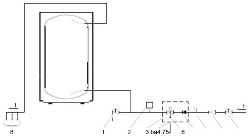
For safety reasons the supply pipe must be fitted with a safety valve that prevents the pressure in the tank from exceeding nominal pressure by more than 0.1 MPa (1 bar). The outlet opening on the relief valve must be equipped with an outlet for atmospheric pressure. In order to provide correct operation of the safety valve, periodical inspections of the relief valve must be carried out by the user to eliminate any limescale and check if the safety valve is blocked. To check the valve, open the outlet of the safety valve by turning the handle or unscrewing the nut of the valve (depending on the type of the valve). The valve is operating properly if the water comes out of the nozzle when the outlet is open. The heating of water in the heater causes the pressure in the tank to increase to the level set by the safety valve. As the water cannot return to the water supply system, this can result in dripping from the outflow of the safety valve. The drip can be piped into the drain by installing a catching unit just below the safety valve. The drainpipe fitted under the safety valve outflow must be piped down in a straight vertical line and located in an environment free from the onset of freezing conditions.
In case the existing plumbing does not enable you to pipe the dripping water from the return safety valve into the drain, you can avoid the dripping by installing expansion tank on the inlet water pipe of the boiler. Volume of expansion vessel should represent about 3% of water tank volume.
The hot water tank may be connected to the household water supply system without a pressure-reducing valve provided the supply mains pressure is less than 0.6 MPa (6 bar). In case of the mains pressure exceeding 0.6 MPa, a pressure-reducing valve must be installed to ensure that the pressure on the supply side of the heater does not rise above the nominal value.
Legend:
1 - Drain valve
2 - Expansion tank
3 - Safety valve
a - Test valve
b - Non-return valve
4 - Funnel outlet to the drain
5 - Test unit
6 - Pressure-reducing valve
7 - Stop valve
8 - Water tap
H - Cold water
T - Hot water

WARNING: The heating pump should not be in operation without water in the hot er tank, because of danger of destruction of the compressor.
INSTALLATION OF THE HOT WATER TANK AND HEATING PUMP
The hot water tank with heating pump can be used using the ambient air or air from other premises.
Operation using ambient air
In this type of operation, the device heats domestic water using only the amount of energy generated by the air from the room where the device is installed. The hot water tank with heating pump can be installed in in a dry room where it is not freezing, possibly in the vicinity of other sources of heating, with the temperature ranging from 7 to 35 °C and no larger than 20 m ^3 . Generally, we suggest a large enough and well-ventilated room with the temperature ranging between 15 and 25 °C, which represents optimal conditions for the operation of the heating pump. When selecting the room for installing the hot water tank and heating pump, one should make certain that the selected room is not too exposed to dust, because dust has adverse effects on the efficiency of heating pumps.
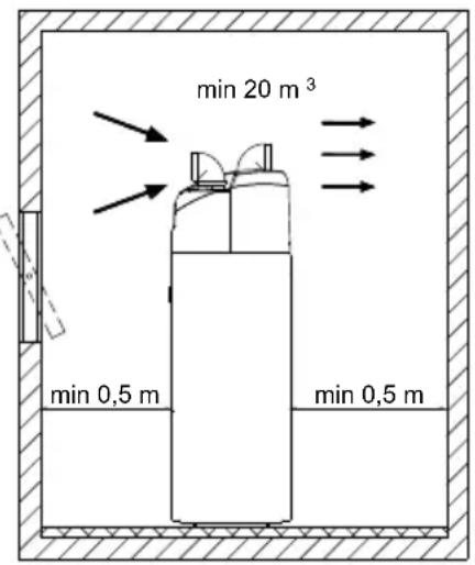
Before the beginning of the operation two 90° elbows must be installed to the top of the appliance (ø150 mm), each facing in the opposite direction. The premises must be properly ventilated.
Operation using air from other premises
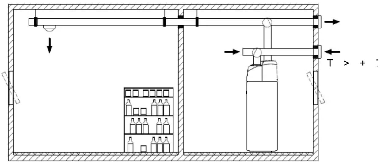
In this type of operation, the heating pump brings air in and out of other premises through a system of pipes. The pipes must be properly insulated to avoid condensation inside the pipes. In case of using air from outside, the external part must be covered so as to prevent the intrusion of dust or snow into the appliance.
To make the operation of the heating pump efficient at all times, you can install flow-directing flaps to take in air from the premises or from outside and then return it when necessary. The temperature of the air should always be above 7 °C .
Pressure loss in case of using the pipeline system
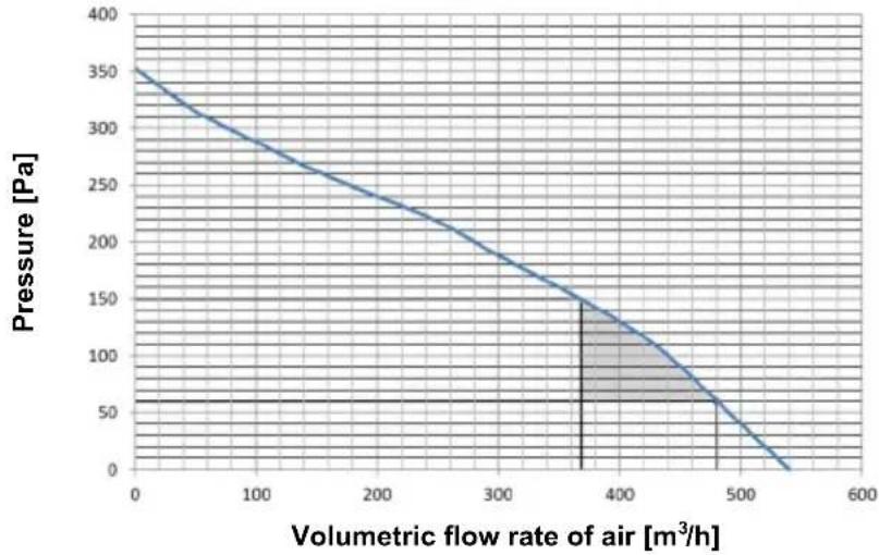
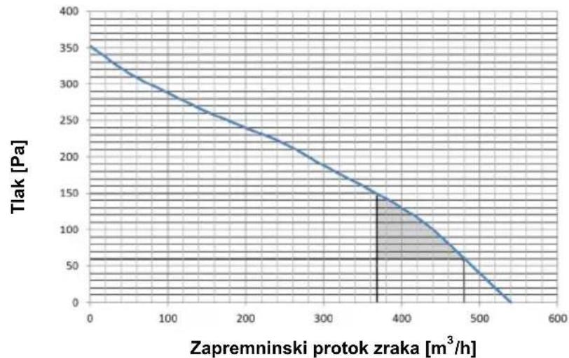
In planning the pipeline system for the inlet and outlet of air to and from the heating pump, the key element is to take into account the aerodynamic character of the fan which also causes the loss of static pressure. The aerodynamic character of the fan is also demonstrated on the diagram and is represented as pressure loss due to air flow. The operating point of the fan is at 60 Pa of static pressure, or at the air flow rate of 480 m³/h. The acceptable level of pressure loss in the air pipeline in our heating pumps is Δp ≤ 90 Pa. In case of such a drop in static pressure in the pipeline, the volumetric air flow rate is 370 m³/h. COP values within the allowed area of pressure drops do not change significantly, i.e. they do not drop by more than 10%.
line
| Volumetric flow rate of air [m³/h] | Pressure [Pa] | | ---------------------------------- | ------------- | | 0 | 350 | | 100 | 300 | | 200 | 250 | | 300 | 200 | | 400 | 150 | | 500 | 100 | | 600 | 50 |Aerodynamic character of the fan
The values of the total loss of pressure can be calculated by adding up the losses of individual elements built into the pipeline system. The values of static pressure losses of individual elements (static pressure drops refer to inner diameter of 150 mm) are provided in the table below.
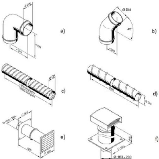
Schematic demonstration of the basic elements in a pipeline system for inlet and outlet of air
| Type of element Value of static pressure loss | |
| a) Elbow 90° 5 Pa | |
| b) Elbow 45° 3 Pa | |
| c) Flexible tube 5 Pa/m | |
| d) Spyro pipe 3 Pa/m | |
| e) Air intake grid 25 Pa | |
| f) Roof vent for waste air 10 Pa | |
Types of elements and corresponding static pressure losses
As mentioned above, the total loss of static pressure, which can be calculated by adding up the losses of individual elements built into the pipeline system, may not exceed 90 Pa. If they do, the values of COP start dropping more dramatically.
Example of calculation:
| Number of elements | Δp (Pa) | ΣΔp (Pa) | |
| Elbow 90° | 4 | 5 | 20 |
| Flexible tube | 7 | 5 Pa/m | 35 |
| Air intake grid | 1 | 25 | 25 |
| Roof vent for waste air | 1 | 10 | 10 |
| Total: | 90 |
To prevent pressure depression in the building, fresh air must be regularly supplied to the premises. The desired rate of air exchange for a residential building is 0.5. This means that the entire quantity of air in the building is exchanged every two hours.
Connecting the heating pump to the same pipeline as the kitchen extractor fan or taking air out of several smaller apartments or suites is not allowed.
During the operation of the heating pump, condensate is formed in within the aggregate. It must be led into the sewage by means of a flexible condensate
drainpipe 16 mm on the backside of the heat pump. The quantity of condensate depends on air temperature and humidity.
natural_image
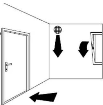
Simple line drawing of a door opening with directional arrows indicating movement or flow (no text or symbols)To reduce the transfer of noise and vibrations of the built-in fan, please take the following measures to prevent the transfer of noise and vibrations through the walls into premises where this would be disturbing (bedrooms, rooms intended for resting):
- install flexible joints for hydraulic connections
- install a flexible tube for the pipeline of inlet/outlet air
- plan vibration insulation for wall openings
- plan noise dampers for inlet/outlet air
- pipelines for inlet/outlet air should be attached using noise dampers
- plan insulation to prevent floor vibrations
- use positioning feet.
After the water tank with heating pump is connected to water supply (heating) network and filled with water, the heating pump is connected to power supply network and ready for operation. The appliance should be connected to the power supply network in compliance with the national installation regulations.
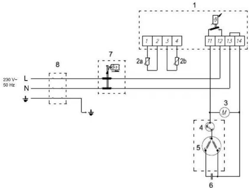
Legend:
1 - Electronic regulator
2a - Temperature sensor - surroundings
2b - Temperature sensor - boiler
3 - Motor of the fan
4 - Thermal protection
5 - Compressor
6 - Operating condenser
7 - Thermal cut-out
8 - Connection terminal
L - Live conductor
N - Neutral conductor
± - Earthing conductor
Electric installation
Switch the pump on with the main switch. The heating pump starts operating and operates until the switch-off temperature is reached (factory set to 55 °C). After switching off, the operation is interrupted until the water temperature falls by 5 °C (e.g. to 50 °C), when the heating pump starts operating again.
The user may adjust the switch-off temperature of water to max. 55 °C (thermostat blocking) or optionally reduce it up to min. (thermostat blocking).
Legend:
1 - Heat pump switch on
2 - Legionella Control switch on
3 - Control lamp - heat pump operation
4 - Control lamp - Legionella Control switch on
5 - Display
6 - Temperature setting - increase
7 - Temperature setting - reduce
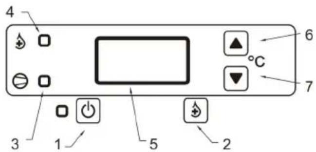
After connecting the heat pump to power supply, the display shows servicing markings and then the temperature value. If the water temperature in the hot water tank is lower, the heat pump is automatically switched on (the red signal lamp 3 is on). To turn the off the operation of the heat pump, press the key 1 (ca. 2 seconds). The operation of the heat pump is switched off; the display shows the marking OFF.
Switching on the Heat Pump
Press key no. 1 and keep it pressed for some 2 seconds. The display shows the current water temperature in the hot water tank, the signal lamp 3 switches on.
Temperature Setting
Pres and release key 6 or 7. When the key is pressed, the display shows the marking °C. Now you can set the required temperature. With key 7 the temperature is reduced and with key 6 the temperature is increased. When the setting is completed, the marking on the display starts flashing. After eight flashes the new temperature is set, and the display shows the temperature of the water in the hot water tank. In versions with installed thermometer, the thermometer will show ambient temperature, while the display on the heat pump will show the temperature of water in the lower part of the water heater. This is why the two temperatures will vary.
WARNING: If the heating pump is operating outside the temperature zone of operation, the evaporator may freeze. Then, the heating pump switches off, and the display shows the marking tLo. After switching off the heating pump will remain inoperational until the evaporator unfreezes.
Legionella Control Programme
Your heat pump features a system for thermal disinfection for legionella prevention. This system includes a special function for high temperature heating (up to 65 °C ) of water in the hot water tank. The system operates automatically, switching on the high temperature heating of water every 14 days. When the temperature in the water tank reaches 65 °C , the high temperature heating is switched off.
High temperature heating can also be activated manually, by pressing the key 2 (ca. 5 seconds). The display alternatively shows the temperature of water in the hot water tank and marking LEG. When the temperature in the hot water tank reaches 65^ C, the heat pump is switched to normal operation.
Indicator of errors and warnings
| Error Description Solution | ||
| Er1 | Error - Temperature sensor 2a (disconnected, faulty connection, short circuit) | Call your service provider. |
| Er2 | Error - Temperature sensor 2b (disconnected, faulty connection, short circuit) | Call your service provider. |
| tLo | Inlet air temperature too low. | When the inlet air temperature rises, the water pump starts functioning normally. |
| LEG Heat | pump is operating in the anti-legionella mode. | When the water temperature in the tank reaches 65 °C, the heat pump starts functioning normally. |
| Control lamp 3 is flashing | Delayed start of the heating pump. | The heating pump starts functioning after the time delay is finished. |
WARNING: Even after switching off with the switch, the elements in the electric control unit are live!
USE OF ELECTRIC HEATING ELEMENT (only models with electric heating elements)
The built-in electric heating elements, type SH are designed as backup heating of water in closed and open type water heaters.
During operation, the heating element and protection tube of the probe should be sufficiently immersed into water.
Temperature of the electric heater housing should not exceed 80 °C.
The installation should be carried out in compliance with the requirements defined by the applicable regulations as well as local power supply regulations. The heater may be connected by an authorised technician only.
Direct the power supply cord through the cable entry to the terminal pin in the electric heater. Take into account the dimensions of the power supply cord (3x2,5 mm ^2 or 5x1,5 mm ^2 ).
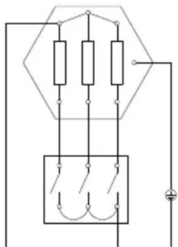
Connect the built-in electric heater to power supply network (in compliance with the wiring diagram) and take into account the correct voltage values. Before putting into service check if the wiring of the unit is made in compliance with the wiring diagram.
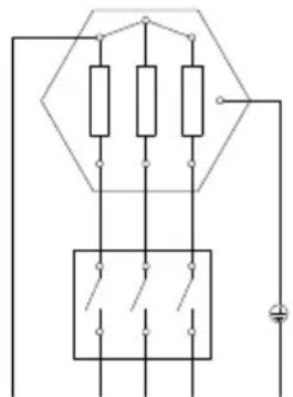
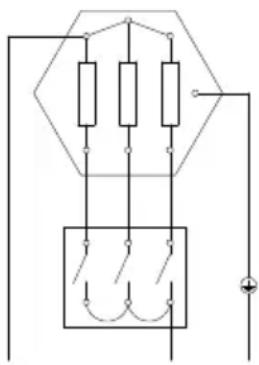
Electric wiring of the heaters with power of 2 kW or more is factory set to three-phase voltage of 3\~400 V (Figure 1) designed for direct regulation. Electric heaters with 2 kW power can be connected to single-phase voltage of 230 V (Figure 2) or to three-phase voltage of 400 V (Figure 1), where the star connection should not be connected to the ground conductor. The bridge connections on the terminal pin should be made of 1,5 mm ^2 copper wire.
- Rotate the protective cover to the required position by removing the cover, turn it around and mount it again. The sealing on the housing should not be moved in any way and be careful not to damage it. Use original screws with washers. Damages caused by unprofessional installation of the electric heaters will not be covered by the guarantee.
natural_image
Pure electrical circuit lines without any symbolsN PE L1 L2 L3
Figure 1: Three-phase voltage 400 V (default setting) (max. 3 kW)
natural_image
Pure electrical circuit lines without any symbolsL PE
Figure 2: Single-phase voltage 230 V
WARNING: Do not forget to connect ground conductor!
The water heater must be connected with water inlet and outlet pipes. Other metal parts of the water heater with which the user may come in contact with and which may come in contact with water, should have permanent and reliable connection to ground conductor. Connecting the heater to the electrical circuit must take place in accordance with the standards for electrical appliances. An all-pole disconnect device must be installed between the heater and the electrical circuit to comply with the
national installation regulations. Automatic fuse may also be used as circuit breaker.
Connection to water supply network
Take into account instructions for installation, connection and use of the water heater. Make sure the water heater cannot be switched on when empty.
Starting up
Fill the heater with water before connecting to the power supply network. Supervise the first heating cycle. During the heating cycle, the water expands and with closed-pressure connecting system the water starts dripping from the relief valve, while with open-non-pressure connecting system the water starts dripping from the water tap. Monitor the automatic switching off of the thermal regulator.
Any repairs should be made using original spare parts only!
User's instructions
- Occasionally remove the lime scale deposits on the electric heating element (the intervals depend on the hardness of water of your water supply and on the operating conditions. We recommend installing a device for regulation of water hardness or you can reduce the temperature for heating the water. Any damages resulting from damaged electric heating element caused by lime scale depositing, shall not be covered by guarantee.
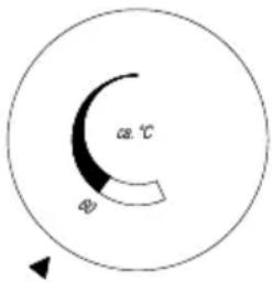
- Taking into account the quantity of hot water required, the temperature in the water heater is continuously adjustable with thermal regulator. Maximum setting of the temperature is ca. 75 °C, and minimum temperature setting is ca. 9 °C. When setting to 75 °C, the temperature is reduced to ca. 65 °C before the heater is again switched on. In order to prevent lime scale depositing on the heating element, we recommend setting the thermal regulator to temperature setting lower than 60 °C, as evident on the drawing bellow:
- In case of malfunctions or defects during the operation of the heater, call the nearest authorised service provider. An expert will repair the malfunction or defect in no time and will restore the operation of the water heater.
Do not try to repair the heater by yourself! Call the nearest authorised service provider.
CONNECTION TO ALTERNATIVE SOURCES OF HEATING
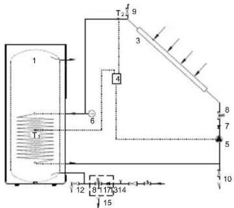
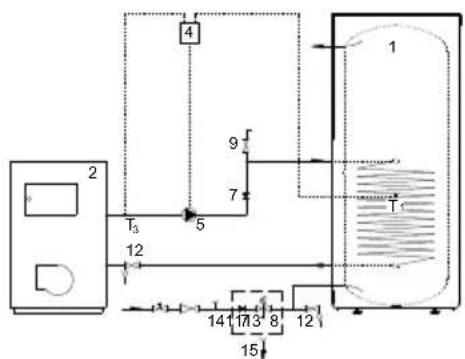
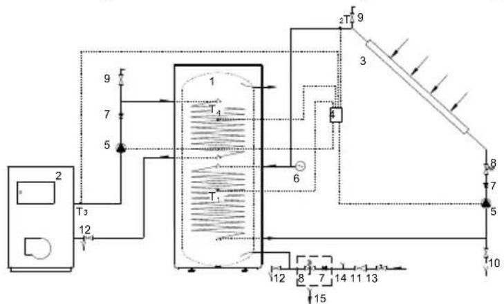
The heaters with heating pump enable the water for sanitary use to be heated by alternative sources of energy (e.g. central heating, solar power, ...) by installing one or two heat exchangers.
Options for connecting the water heater to various sources of heating are shown in
the drawings below.
Connection to solar panels Connection to the central
heating hot-water system
flowchart
graph TD
    A["1"] --> B["T1"]
    B --> C["6"]
    C --> D["T2"]
    D --> E["9"]
    D --> F["3"]
    D --> G["4"]
    G --> H["8"]
    G --> I["7"]
    G --> J["5"]
    G --> K["10"]
    B --> L["12"]
    B --> M["8"]
    B --> N["17"]
    B --> O["314"]
    B --> P["15"]
    style A fill:#f9f,stroke:#333
    style B fill:#ccf,stroke:#333
    style C fill:#cfc,stroke:#333
    style D fill:#fcc,stroke:#333
    style E fill:#cff,stroke:#333
    style F fill:#ffc,stroke:#333
    style G fill:#cfc,stroke:#333
    style H fill:#fcc,stroke:#333
    style I fill:#ffc,stroke:#333
    style J fill:#cfc,stroke:#333
    style K fill:#fcc,stroke:#333
    style L fill:#cfc,stroke:#333
    style M fill:#fcc,stroke:#333
    style N fill:#cfc,stroke:#333
    style O fill:#cfc,stroke:#333
    style P fill:#cfc,stroke:#333
flowchart
graph TD
    A["2"] --> B["T3"]
    B --> C["5"]
    C --> D["4"]
    D --> E["1"]
    C --> F["7"]
    F --> G["9"]
    G --> H["14"]
    H --> I["17"]
    I --> J["8"]
    J --> K["12"]
    K --> L["15"]
    style A fill:#f9f,stroke:#333
    style L fill:#f9f,stroke:#333
Connection to solar panels and central heating hot-water system
flowchart
graph TD
    A["2"] --> B["T3"]
    B --> C["12"]
    C --> D["T4"]
    D --> E["6"]
    E --> F["4"]
    F --> G["2T"]
    G --> H["9"]
    H --> I["3"]
    I --> J["8"]
    J --> K["7"]
    K --> L["5"]
    L --> M["10"]
    M --> N["15"]
    N --> O["12"]
    O --> P["8"]
    P --> Q["7"]
    Q --> R["14"]
    R --> S["11"]
    S --> T["13"]
    T --> U["15"]
    U --> V["12"]
    V --> W["15"]
Legend:
1 - Water heater
2 - Central heating hot-water system
3 - Solar panel
4 - Differential thermostat with sensors (T1, T2, T3, T4)
5 - Bypass pump
6 - Expansion tank
7 - Non-return valve
8 - Safety valve
9 - Air relief valve
10 - Fill/drain valve
11 - Reduction valve
12 - Drain valve
13 - Stop valve
14 - Test unit
15 - Funnel outlet to the drain

WARNING: If the temperature of the additional heating source drops and the circulation of water through the heat transmitter is enabled the heat can uncontrollably be taken from the water tank. When attaching the appliance to other heating sources, the additional source temperature must be properly regulated.

WARNING: In case of connecting solar panels as an external source of heat, the operation of the aggregate of the heating pump must be turned off. A combination of those two sources can lead to overheating of the domestic water, resulting in excessively high pressures.

WARNING: Circulation line can lead to additional heat losses in the water tank.
USE AND MAINTENANCE
The unit is ready for use once it has been connected to water and electricity. If there is danger of freezing, discharge the water from the hot water tank. Open the hot water tap, connected to hot water tank. Let the water pour our through the discharge valve on the inlet hose.
The exterior of the water heater may be cleaned with a mild detergent solution. Do not use solvents and abrasive cleaning agents. If the heating pump is exposed to dust, the lamellas of the evaporator can freeze, which can have detrimental effects to its functioning.
Regular preventive maintenance inspections ensure faultless performance and long life of your heating pump. The first of these inspections should be carried out by the authorised maintenance service provider within two years from the date of installation in order to check the wear of the protective anticorrosion anode and remove any build-up of calcium and lime as required. The build-up of calcium and lime in the hot water tank depends on the quality, quantity and temperature of water flowing through the heating pump. The maintenance service provider shall also prepare a status report and consequently recommend the date of the next inspection.
In spite of monitored manufacture and final control, it may happen that failure occur during the operation of the heating pump. Should this happen, call your authorized service provider.
Before calling your service provider, check the following:
- Is everything OK with the power supply network?
- Is the air outlet obstructed (evaporator may freeze)?
- Is ambient temperature too low (evaporator may freeze)?
- Can you hear the operation of the compressor and fan?
Do not try to eliminate malfunctions by yourself, call your nearest authorized service provider!
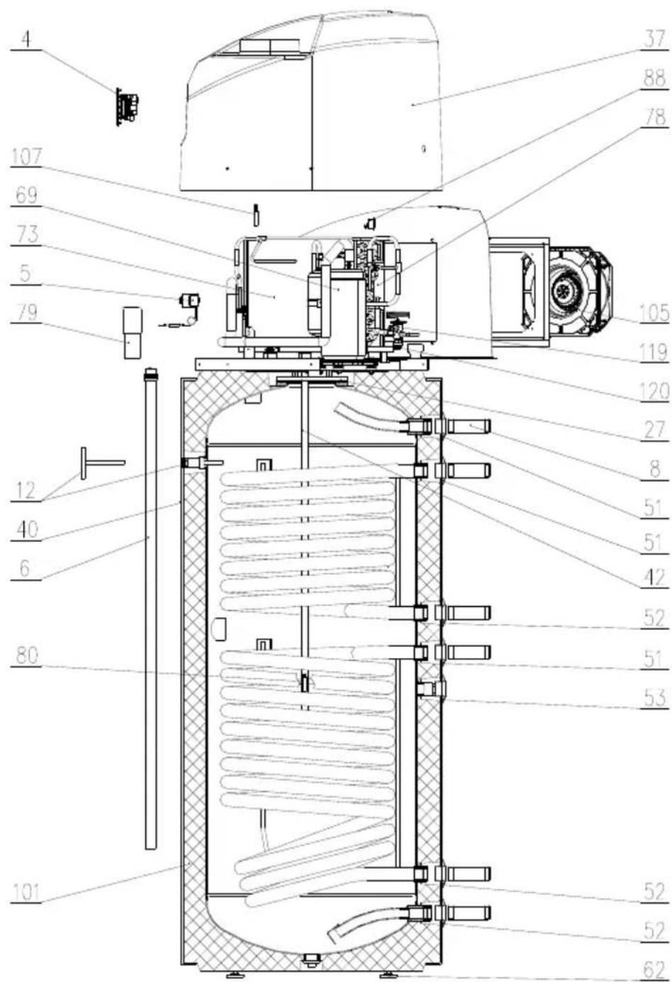
| Position | Ident | Spare part description | Quantity | Validity |
| 4 | 385882 | Thermoregulator | 1 | |
| 5 | 487110 | Thermal cut-out | 1 | |
| 6 | 269457 | Sacrifying anode D26x742/730-G1 | 1 | PAW-DHWM200ZC |
| 6 487 | 348 | Sacrifying anode D26x1062/1050-G1 | 1 | PAW-DHWM300ZC PAW-DHWM300ZE |
| 8 | 765082 | Outlet tube G1x105 | 4 | |
| 12 | 765012 | Bimetal thermometer | 1 | |
| 27 | 765011 | Gasket 180/114x3 | 1 | |
| 37 | 408924 | Cap | 1 | |
| 40 | 479610 | Coating | 1 | PAW-DHWM200ZC |
| 40 | 479621 | Coating | 1 | PAW-DHWM300ZC |
| 40 | 479622 | Coating | 1 | PAW-DHWM300ZE |
| 42 | 407211 | Flange | 1 | |
| 51 | 765085 | Rosette D34 G1 RD | 2 | |
| 52 | 765084 | Rosette D34 G1 BU | 2 | |
| 53 | 765086 | Rosette D32 G3/4 BU | 1 | |
| 62 | 765083 | Adjustable foot M12x71 | 4 | |
| 69 | 407206 | Compressor | 1 | |
| 73 | 408787 | Evaporator | 1 | |
| 78 | 364934 | Drying filter 30 g | 1 | |
| 79 409 | 396 | Capacitor 15μF | 1 | |
| 80 765 | 106 | Probe of thermoregulator L2000 | 1 | |
| 88 | 419221 | Thermal cut-out | 1 | |
| 101 | 408708 | Water tank | 1 | PAW-DHWM200ZC |
| 101 | 408709 | Water tank | 1 | PAW-DHWM300ZC |
| 101 | 408710 | Water tank | 1 | PAW-DHWM300ZE |
| 105 | 378114 | Fan | 1 | |
| 107 | 346060 | Probe of thermoregulator L1000 | 1 | |
| 119 | 440608 | Thermal expansion valve TUB-R134 | 1 |
natural_image
Diagram showing a door opening with directional arrows indicating movement or force (no text or symbols)natural_image
Pure electrical circuit lines without any symbolsN PE L1 L2 L3
N
L
natural_image
Pure electrical circuit lines without any symbols
natural_image
Diagram showing a door opening with directional arrows indicating movement or force (no text or symbols)natural_image
Simple line drawing of a door opening with directional arrows indicating movement or flow (no text or symbols)natural_image
Simple line drawing of a door with directional arrows indicating movement or flow (no text or symbols)sensorer (T1, T2, T3, T4)
5 - Omløbspumpe
6 - Ekspansionstank
7 - Kontraventil
natural_image
Diagram showing airflow direction from a door to an exit, with arrows indicating movement (no text or symbols)natural_image
Simple line drawing of a door with directional arrows indicating movement or flow (no text or symbols)Definiranje pada tlaka pri cjevovodnome sustavu dovoda i odvoda zraka
Pri samome planiranju cjevovodnoga sustava za dovod i odvod zraka u toplinsku crpku, odnosno iz nje, od ključne je važnosti uvažavanje aerodinamičkoga svojstva ventilatora iz kojeg također izlazi raspoloživ gubitak statičnoga tlaka. Aerodinamičko svojstvo ventilatora prikazano je na grafikonu i predstavljeno kao pad tlaka u ovisnosti o protoku zraka. Radna točka ventilatora toplinske crpke jednaka je 60 Pa statičnoga tlaka, odnosno pri protoku zraka od 480 m³/h. Kao još prihvatljiv pad statičnoga tlaka u zračnome cjevovodu, za naše se toplinske crpke smatra Δp ≤ 90 Pa. Pri spomenutom ukupnom padu statičnoga tlaka u cjevovodu zapremninski protok zraka iznosi 370 m³/h. Vrijednosti COP ne mijenjaju se znatno u dopuštenom opsegu pada tlakova, odnosno smanjuju se za manje od 10%.
line
| Zapremninski protok zraka [m³/h] | Tlak [Pa] | | -------------------------------- | --------- | | 0 | 350 | | 100 | 300 | | 200 | 250 | | 300 | 200 | | 400 | 150 | | 500 | 100 | | 600 | 50 |Aerodinamičko svojstvo ventilatora
natural_image
Diagram showing a door opening with directional arrows indicating movement or flow (no text or symbols)kondenzat na poleđini toplinske crpke. Količina kondenzata ovisi o temperaturi i vlažnosti zraka.
natural_image
Simple line drawing of a door opening with directional arrows indicating movement or force (no text or symbols)Program Anti-Legionella
natural_image
Simple line drawing of a door with directional arrows indicating movement or flow (no text or symbols)natural_image
Simple line drawing of a door opening with directional arrows indicating movement or flow (no text or symbols)- Installation Instructions, Operating Instructions, Spare Parts List
- CHILDREN SHOULD BE SUPERVISED TO ENSURE THAT THEY DO NOT PLAY WITH THE APPLIANCE.
- CONNECTION TO THE WATER SUPPLY
- Legend:
- INSTALLATION OF THE HOT WATER TANK AND HEATING PUMP
- Operation using ambient air
- Operation using air from other premises
- Pressure loss in case of using the pipeline system
- Switching on the Heat Pump
- Temperature Setting
- Legionella Control Programme
- USE OF ELECTRIC HEATING ELEMENT (only models with electric heating elements)
- WARNING: Do not forget to connect ground conductor!
- Connection to water supply network
- Starting up
- User's instructions
- CONNECTION TO ALTERNATIVE SOURCES OF HEATING
- USE AND MAINTENANCE
- Definiranje pada tlaka pri cjevovodnome sustavu dovoda i odvoda zraka
- Program Anti-Legionella
Brand : PANASONIC
Model : PAW-DHWM300ZE
Category : Air-conditioner