
WS89 - Range hood Witt - Free user manual and instructions
Find the device manual for free WS89 Witt in PDF.


| Product Type | Range Hood |
| Brand | Witt |
| Model | WS89 |
| Installation Type | Wall-mounted |
| Extraction Modes | Ducted (sucking) and Recirculating (filtering) |
| Number of Speeds | 4 |
| Timer | Yes, 10-minute automatic shut-off |
| Lighting | Yes, replaceable square LED lamps |
| Grease Filter | Washable (hand or dishwasher) |
| Charcoal Filter | Replaceable (for recirculating mode) |
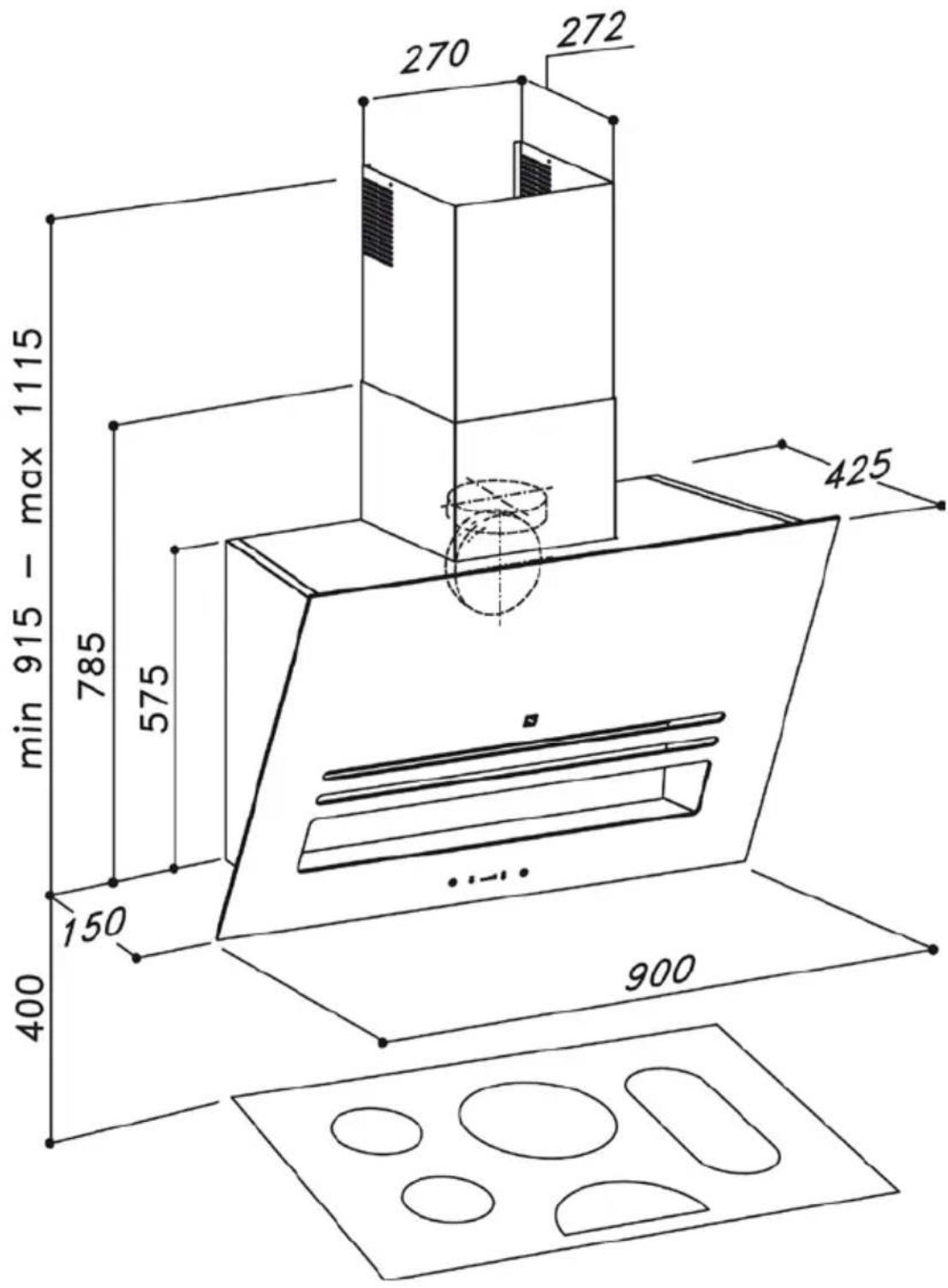
| Minimum Distance to Ceramic Hob | 450 mm |
| Minimum Distance to Gas Hob | 500 mm |
| Power Supply | 220-240 V (refer to label) |
| Control Type | Push-button |
| Material | Stainless steel |
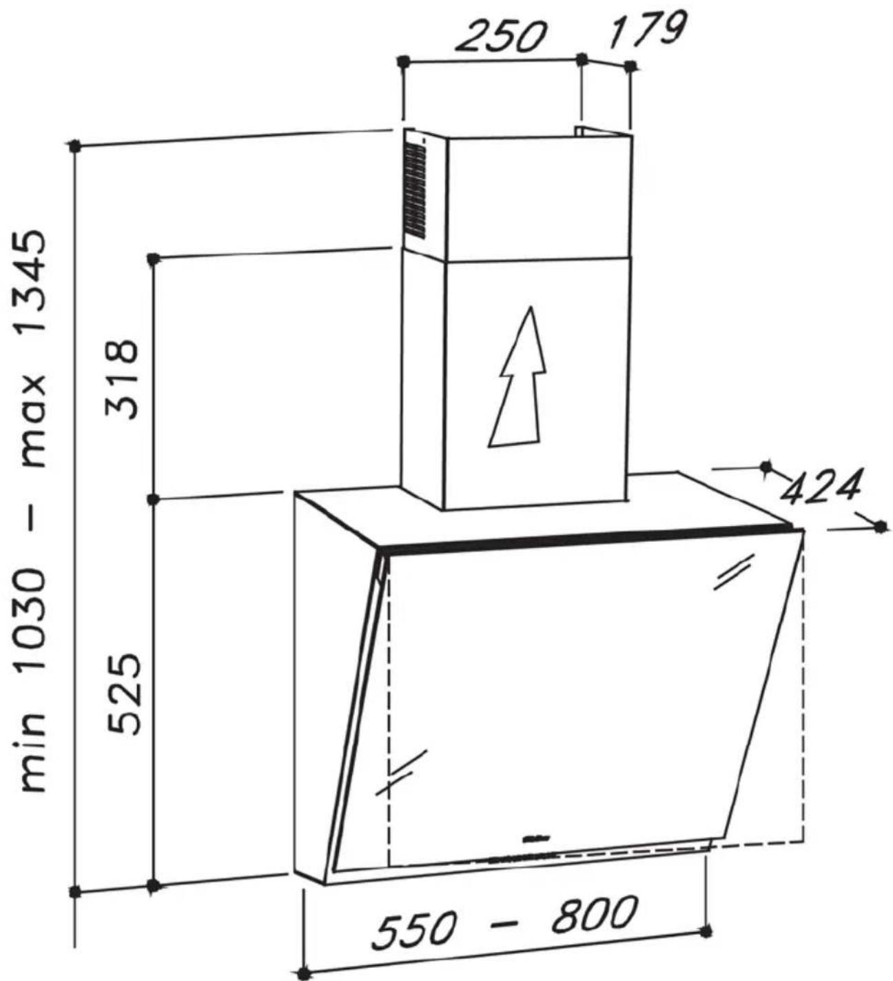
| Chimney Height Adjustment | 1030 mm to 1345 mm |
| Warranty | 2 years |
| Customer Service | Phone: 01483 516633, Email: support@witt-ltd.com |
Frequently Asked Questions - WS89 Witt
User questions about WS89 Witt
0 question about this device. Answer the ones you know or ask your own.
Ask a new question about this device
Download the instructions for your Range hood in PDF format for free! Find your manual WS89 - Witt and take your electronic device back in hand. On this page are published all the documents necessary for the use of your device. WS89 by Witt.
USER MANUAL WS89 Witt
The appliance is not intended for use by young children or infirm persons without supervision. Young children should be supervised to ensure they do not play with the appliance.
The minimum distance between the cook-top surface and the lower part of the cooker hood shall as follows:
WS74: 400 mm distance to ceramic hob 450 mm distance to gas hob
WS76: 650 mm distance to ceramic hob 700 mm distance to gas hob
WS89: 450 mm distance to ceramic hob from the lower part of the hood 500 mm distance to gas hob from the lower part of the hood
The air sucked can't be conveyed through or into a duct used to let out fumes from appliances fed by energy other than electric power (e.g. centralized heating, radiators, water-heaters, etc.).
To evacuate the air outlet, please comply with the pertaining rules given by competent authorities.
Provide the room with an adequate aeration when a cooker hood and appliances fed by energy other than electric power (gas-, oil-, or coal- stoves, etc.) are used simultaneously. The cooker hood, when evacuating the sucked air, could generate a negative pressure in the room- which can't exceed the limit of 0.04 mbar, in order to avoid the suck of exhausts deriving from the heat-source. Therefore the room should be provided with air-intakes to allow a constant flow of fresh air.
The appliance needs earth connection.
When performing the electrical connections on the appliance, please make sure that the current-tap is provided with earth connection and that voltage values correspond to those indicated on the label placed inside the appliance.
Please disconnect the appliance from power mains, before carrying out any cleaning or maintenance operation. If the appliance is not equipped with a non-separable flexible cable and plug, or with another device ensuring omnipolar disconnection from the mains, with an opening distance between the contacts of at least 3 mm, then such disconnecting devices must be provided in the fixed installation.
If the appliance is equipped with a power cord and a plug, it shall be placed in such a way that the plug can be reached easily.
The use of materials which can burst into flames (flambé) should be avoided in close proximity of the appliance. When frying, please pay particular attention to fire risk due to oil and grease. Being highly inflammable, fried oil is especially dangerous. Do not use uncovered electric grills. In order to avoid possible fire risk, all instructions for grease-filter cleaning and for removing eventual grease deposits should be strictly followed.
Uses
The appliance has been designed to work both in filtering and sucking mode.
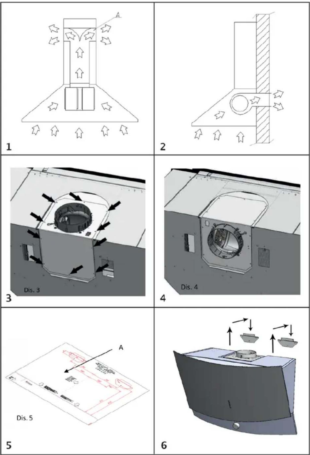
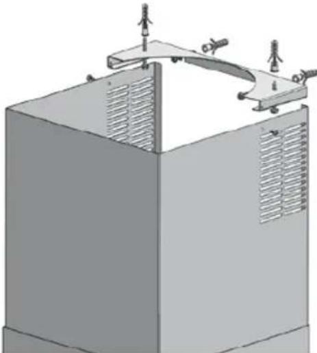
In the filtering version (fig. 1), the air and fumes conveyed by the appliance are purified by both a grease filter and an activated charcoal filter, and then re-circulated into the room through the side-grids of the chimney.
When the appliance works in this mode, we recommend the use of an air deflector (Fig.1A) to be placed on the upper part of the pipe, allowing the air to be re-circulated into the room.
In the sucking version (fig. 2), fumes are directly conveyed outside the building, through the top or rear air out-let. The use of a charcoal filter and air deflector is not necessary in this case.
Installation
Before installing the appliance, make sure that none of the parts is damaged in any way.
In case of damaged parts, contact your retailer and do not proceed with installation. Read all of the following instructions carefully before installing the appliance:
- Use an air outlet pipe of the shortest possible length.
- Limit the number of pipe elbows.
- Use a material approved by standards and regulations.
- Avoid any sudden changes in the pipe section (recommended constant diameter: ∅ 150 mm or equal surface area).
The manufacturer shall not respond for air capacity or noise problems due to non-compliance with above mentioned instructions, and no warranty shall be given.
WS74 has been designed in order to have the possibility of directing the air out-let in the rear side of the appliance; if you chose to use this function, it is necessary to remove the no. 10 screws of the sucking unit support (fig. 3),
take out the sucking unit and rotate it in such a way to direct the air out-let nozzle towards the rear side of the appliance (fig. 4); then place the sucking unit in its seat again and tighten the screws previously removed.
By using its drilling template (fig. 5A), drill the holes for the wall bracket installation.
Appliances shall be installed at a minimum distance:
WS74: 400 mm distance to ceramic hob
450 mm distance to gas hob
WS76: 650 mm distance to ceramic hob
700 mm distance to gas hob
WS89: 450 mm distance to ceramic hob from the lower part of the hood
500 mm distance to gas hob from the lower part of the hood
Fix the brackets to the wall, by using the screw anchors and screws supplied with the product.
Hang the body (fig. 6) to the wall brackets previously fixed.
WS74
Remove the grease filter.
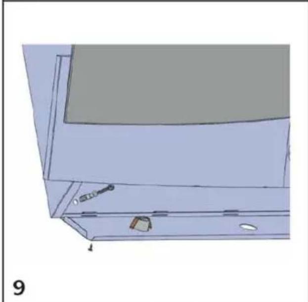
Make sure the hood is securely fixed to the wall, by tightening the inside screws. (fig. 8). Remove the lower light panel fixing screws (fig. 20), rotate the light panel (fig. 21) and fix the appliance to the wall with the screws provided, as per (fig. 9). Reinsert the light panel, the grease filter and close the front panel.
WS76
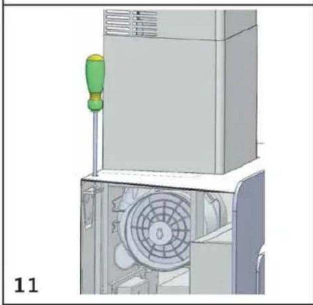
Adjust the position of the hood horizontally and vertically by acting on its screws through its top hole, as per (fig. 11).
Remove the grease filter, held up by magnets, by pulling it downwards (fig. 12).
Remove the front light panel (white), also held up by magnets, by pulling it outwards (fig. 12), then disconnect the bipolar electric connector. Insert the screw anchors and screws provided in the holes indicated by the arrows (fig. 13).
If the appliance is installed in the sucking version, remove the grid covering the motor air outlet (fig. 14).
Reinsert the grease filter and the light front panel, making sure the electric connector is connected properly.
WS89
After you did the drills on the wall, as requested on the preceding chapter (Installation), install the dowel inside the holes and insert two screws inside the two holes on the upper part. Do not tighten the screws completely, but leave about 2mm. between the wall and the head of the screw (fig.25).
Fix the hood on the wall, so that the two screws perfectly coincide with the appropriate hook, placed on the back side of the hood (Fig.26).
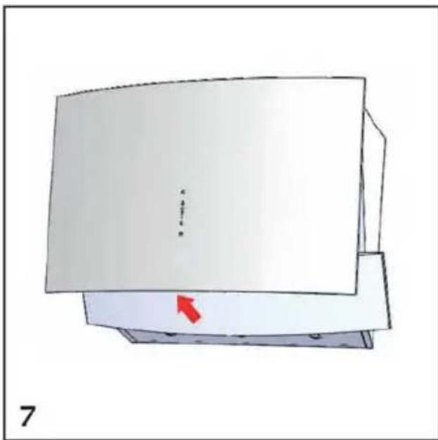
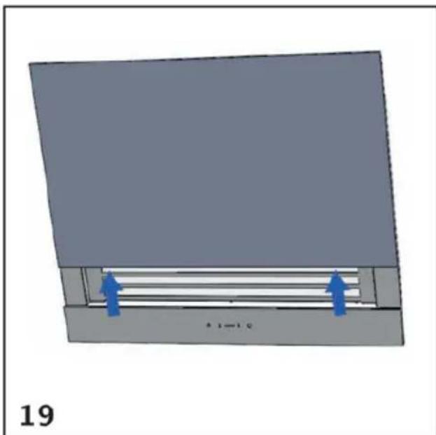
Open the front panel by rotating the lower side upwards.
Remove the grease filter and fix the appliance to the wall with the screws provided.
Sucking version
Fix the pipe bearing bracket to the wall and/or ceiling by using the anchor screws and screws provided (fig. 15), centered to the hood. Connect the motor air-outlet flange to the exhaust hole, by using a suitable pipe. Perform the electric connection. Place the two ornamental pipes on the hood body; lift the internal pipe up until it reaches the ceiling; then fix it to the pipe bearing bracket, by using the two self-threaded screws provided.
Filtering version
Fix the air deflector to the pipe bearing bracket, by using the screws provided. Fix the pipe bearing bracket to the wall and/or ceiling (fig.16), centered to the hood. Connect the motor air-outlet flange to the air deflector, by using a suitable pipe. Perform the electric connection. Place the two ornamental pipes on the hood body; lift the internal pipe up until it reaches the ceiling; then fix it to the pipe bearing bracket, by using the two self-threaded screws provided.
WS89
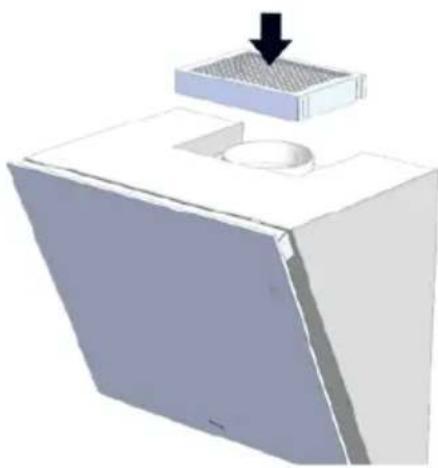
Install the air outlet grill above the hood in the relative seat (refer to fig. 29). The stainless steel chimneys are not necessary.
Dimensions WS74
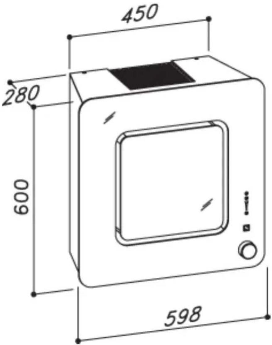
Dimensions WS76
Dimensions WS89
other
| Dimension | Value | | ----------------- | ----- | | min 1030 - max 1345 | 318 | | 550 - 800 | 525 | | 250 | 179 | | 424 | 424 |Working
WS74 – fig. 17
A: ON/OFF lights
B: Speed reduction / OFF motor
C: Speed indicators
D: ON motor/speed increase
E: 10 min timer
The Touch control panel on the glass allows you to set the function desired by lightly touching the corresponding key.
If the electrical power supply is cut, 15 seconds are needed for self diagnostic after its functions are restored. In the meanwhile, its operation may be incorrect.
WS76 - fig. 18
The rotary knob (fig. 18A) allows you to select the various functions of the appliance. All the indicators (fig. 18B) are always lit in the stand-by function.
Functions are selected sequentially by turning the knob. The desired function is set by pressing the knob.
LIGHTS Indicator (fig. 18C)
This function allows you to switch the lights on or off; turn the rotary control until the function is selected then set it by pressing the rotary control.
Timer Indicator (fig. 18D)
By setting this control, at any speed, the appliance will be switched off after 10 minutes. It is necessary to select the control again in order to exit from this function. When the Timer function is set, the Timer indicator will flash and the corresponding speed indicators lit.
Speed Indicators (fig. 18E)
They are lit accordingly to the speed set. OFF Indicator (Fig.18 F): This function allows you to completely switch off the motor; it is totally lit during selection and setting, while it is in stand-by afterwards.
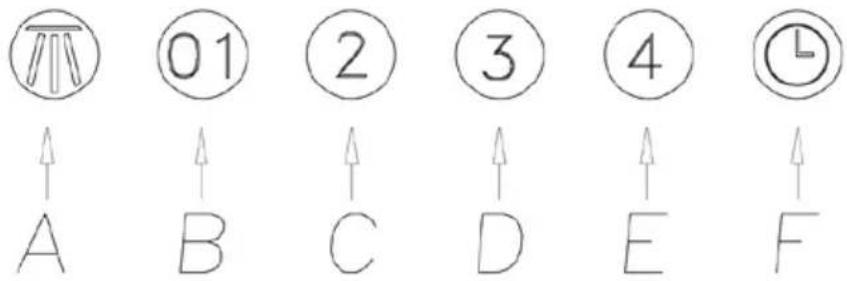
WS89 - fig. 27
A: Light switch on/off
B: Motor switch on/off (1st rate level)
C: 2nd rate level switch
D: 3rd rate level switch
E: 4th rate level switch
F: 10-minute timer
Maintenance
An accurate maintenance guarantees good functioning and long-lasting performance.
Particular care is due to the grease filter. It can be removed by following the instructions below:
WS74
Act on the filter handle and rotate it outwards.
WS76
Remove the filter from the hood by pulling it downwards (fig. 12). Grease filters are inserted by following the reverse procedure.
After 30 hour working, the grease filter saturation will be signaled by the simultaneous lighting of speed indicators; select the timer function with the hood off to reset it
WS89
Open the front glass panel, by acting on its handle and rotate it outwards.
The grease filter needs cleaning by regular hand-washing or in dishwashers, every two months at least, or depending on its use.
If the appliance is used in the filtering version, the activated charcoal filter needs to be replaced periodically.
The charcoal filter is removed by removing the grease filter first, following the instructions above, and then by pulling its special plastic tongue until it is released from its seat. The charcoal filter is inserted by following the reverse procedure.
Tepid water and neutral detergents are recommended to clean the appliance, while abrasive products should be avoided.
The power cord shall be replaced by authorized personnel only.
LED lamp replacement WS74 and WS76
Remove the two fixing screws (fig. 20) and rotate the led light panel, as per (fig. 21). Replace the damaged LED lamp with one of the same kind.
Reinsert the led light panel and fix it by using the screws previously removed.
Fluorescent lamp (neon) replacement WS76
Disconnect the appliance from electricity.
Remove the front panel, which is magnetically supported, as shown in (fig. 12) and disconnect the electric connector.
Place the front panel on a suitable worktop, preventing the appliance from being damaged. Remove the perimeter screws in the lower cover as shown in (fig. 22), remove the lower cover and replace the damaged lamp with another one with same characteristics.
Put back the cover and reinsert the front panel of the hood.
Square lamps WS89
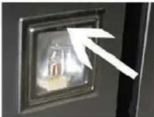
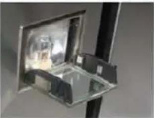
To replace the bulbs in the square lights, press the light frame where it says "PUSH" (fig.28), then replace the bulb and press the frame back into place.
Guarantee
A two year guarantee on manufacture and material defects is granted on your new appliance valid from the documented purchase date. The guarantee includes materials, salary and transport. When contacting service please state the appliance model and serial number.
The guarantee does not cover:
- Defects and damages which are not caused by manufacture and material defects.
• If original spare parts have not been used. - If the instructions in the manual have not been carried out.
- If the installation has not been carried out according to this manual.
- If unauthorized personnel has carried out installation or repair word.
Transport damages
A transport damage observed when the dealer delivers the appliance at the customer is solely a matter between the customer and the dealer. If the customer has carried out the transport alone the manufacture / supplier cannot be held responsible for transport damages. All transport damages must be reported no later than 24 hours after delivery otherwise all claims will be rejected.
Unnecessary service visits
If a service technician is called out to a defect and the customer could have corrected the defect without help e.g. by following the instructions within this manual or by changing a fuse the customer will be charged all service costs – even under guarantee.
Commercial purchase
Commercial purchases are any purchase of appliances not used in a domestic household but instead are used for commercial purposes e.g. in a restaurant, café etc. or used to rent out or used for any other purpose including several users. In case of commercial purchase no guarantee is granted on this appliance since this is only meant for domestic household use.
Service
If you require service please contact us per phone: 01483 516633 or by email: support@witt-ltd.com
natural_image
Diagram of a computer monitor with a red arrow pointing to the front panel (no text or symbols present)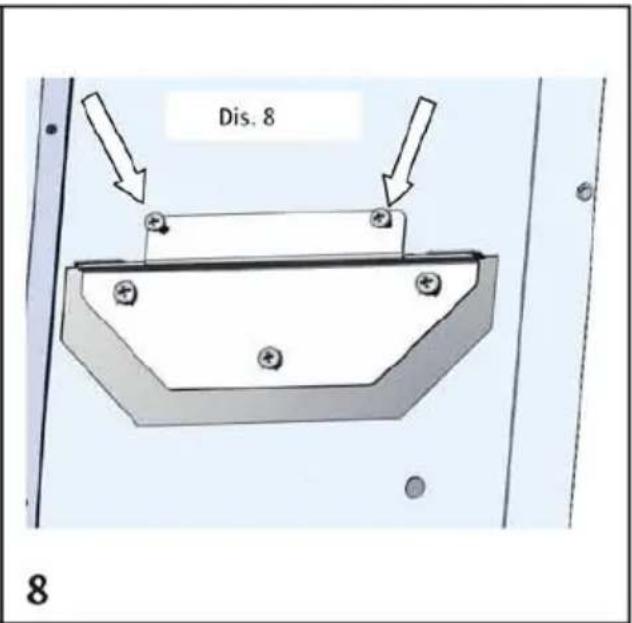
natural_image
3D technical illustration of a mechanical cabinet or shelf with mounting holes and internal components (no text or symbols)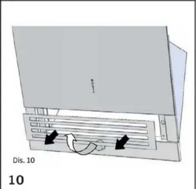
natural_image
3D mechanical assembly diagram showing a screwdriver inserted into a fan component (no text or symbols visible)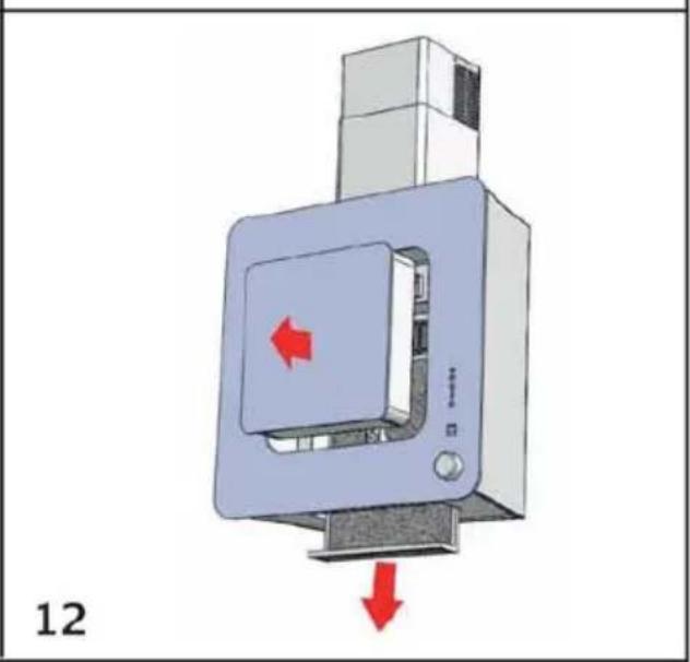
natural_image
Diagram of a computer monitor with red directional arrows indicating left and right motion (no text or symbols)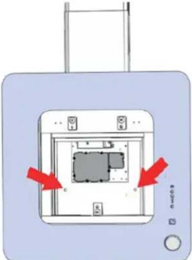 13 13 | 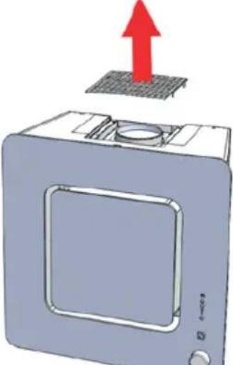 14 14 |
 15 15 | 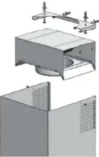 16 16 |
  [7DSC] [TH9] [TH47]A B C D E17 [7DSC] [TH9] [TH47]A B C D E17 | 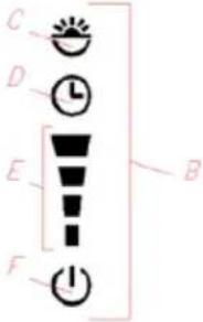 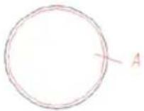 18 18 |
natural_image
3D diagram of a mechanical component with blue arrows indicating force or movement, labeled '19' at bottom left (no text or symbols on the object itself)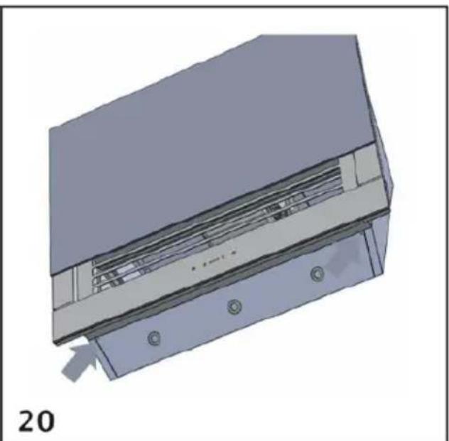
natural_image
3D mechanical component diagram showing internal structure with mounting holes and a labeled part '20' (no text or symbols on the diagram itself)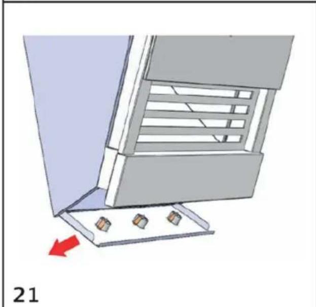
natural_image
3D diagram of a mechanical assembly with three small components and a red arrow indicating direction (no text or symbols)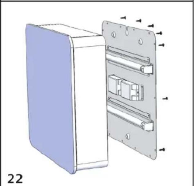
natural_image
3D diagram of a device with internal components and directional arrows, labeled '22' (no text or symbols on the diagram itself)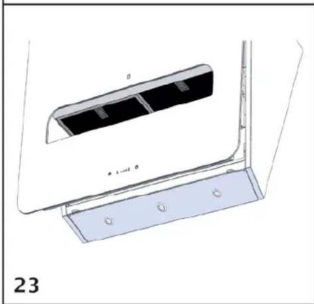
natural_image
Technical line drawing of a mechanical component with two parts, labeled 'a' and 'b', showing mounting holes and a base plate (no text or symbols beyond labels)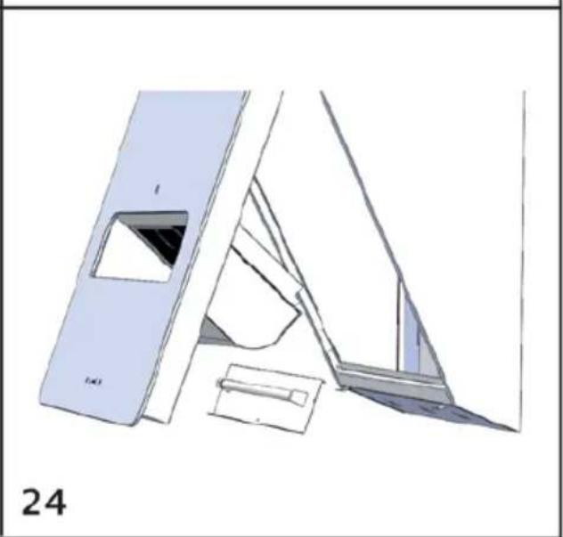
natural_image
Technical line drawing of a mechanical component or bracket assembly (no text or symbols visible)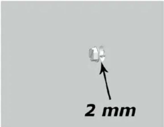 | 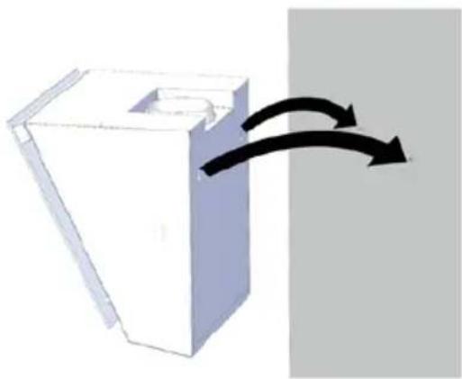 | |
| 25 | 26 | |
 | ||
| 27 | ||
 |  |  |
| 28 | 29 | |
- Uses
- Installation
- WS74
- WS76
- WS89
- Sucking version
- Filtering version
- Dimensions WS74
- Dimensions WS76
- Dimensions WS89
- Working
- WS74 – fig. 17
- WS76 - fig. 18
- LIGHTS Indicator (fig. 18C)
- Timer Indicator (fig. 18D)
- Speed Indicators (fig. 18E)
- WS89 - fig. 27
- Maintenance
- LED lamp replacement WS74 and WS76
- Fluorescent lamp (neon) replacement WS76
- Square lamps WS89
- Guarantee
- The guarantee does not cover:
- Transport damages
- Unnecessary service visits
- Commercial purchase
- Service
Brand : Witt
Model : WS89
Category : Range hood